
A More Sustainable Way for Producing RC Sandwich Panels On-Site and in Developing Countries


Abstract
:1. Introduction
2. Materials and Methods
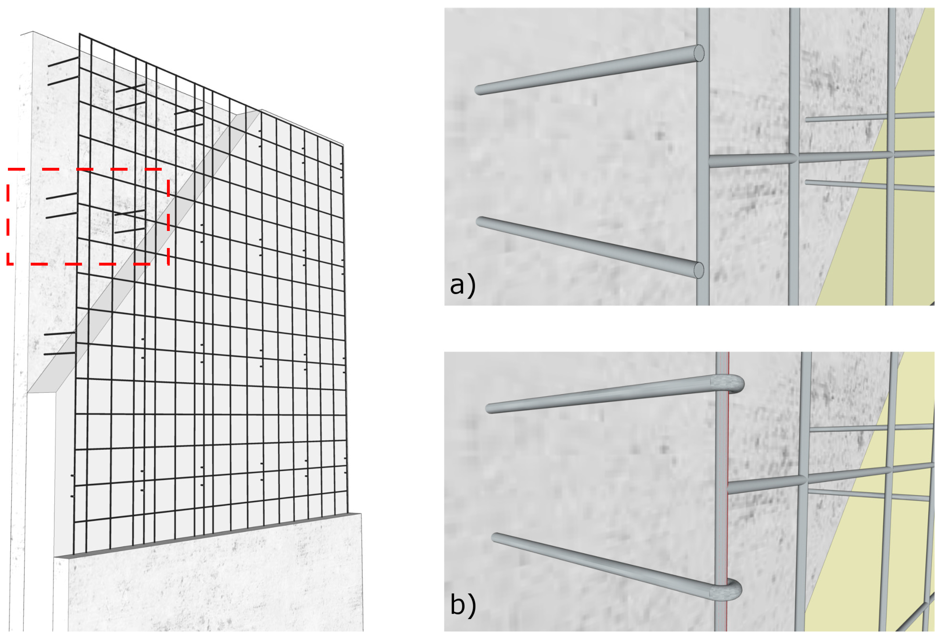
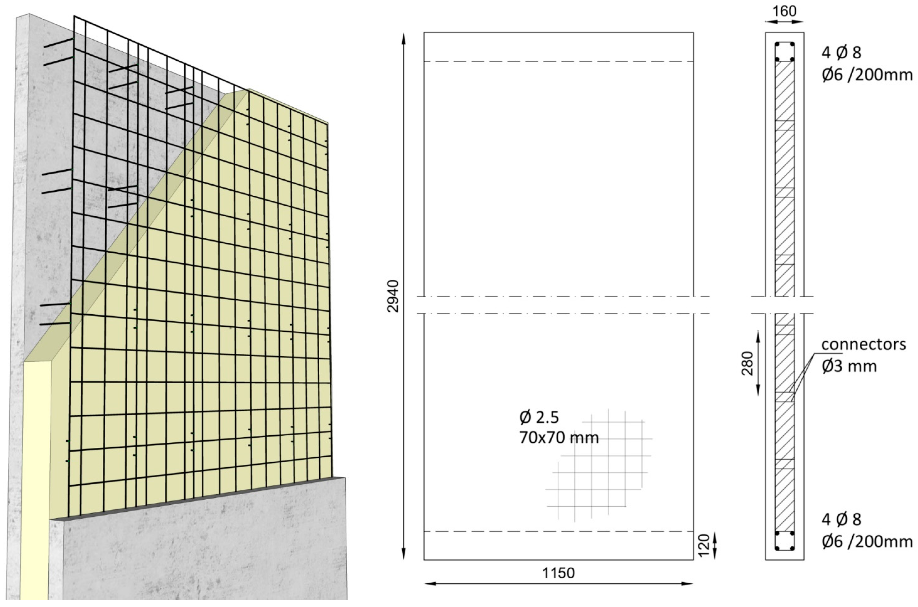
2.1. Materials
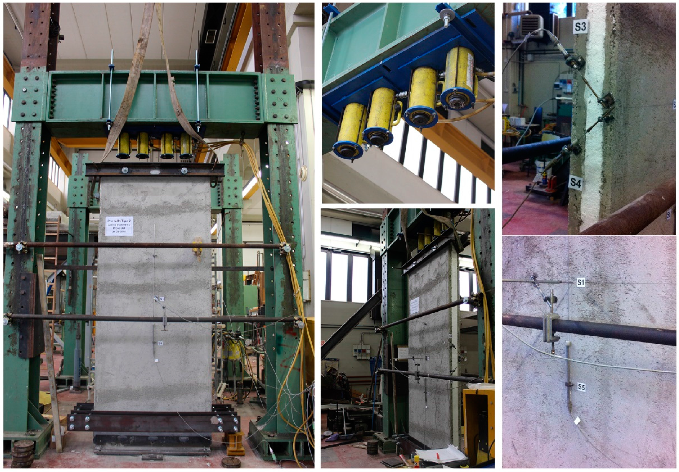
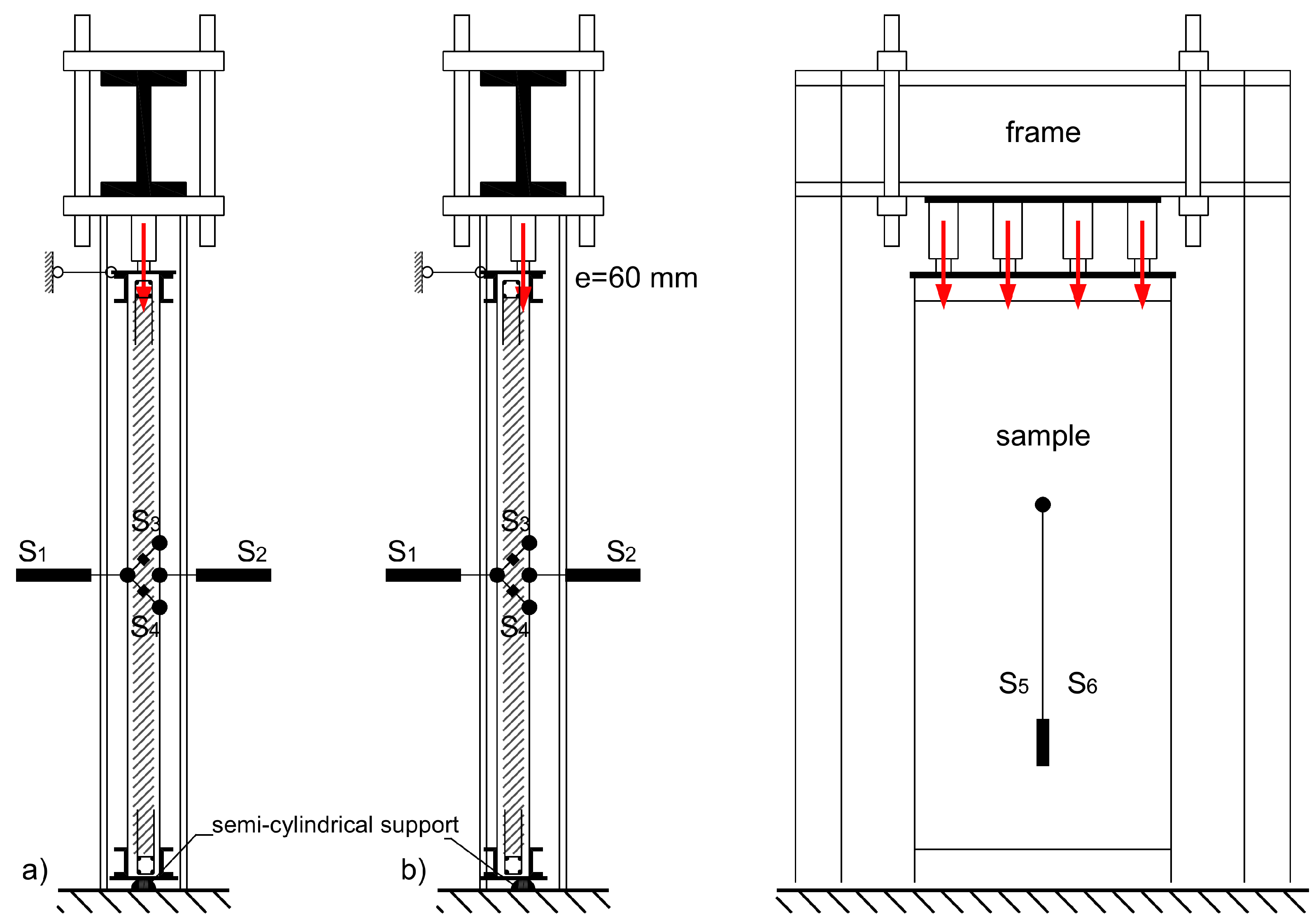
2.2. Compression Test
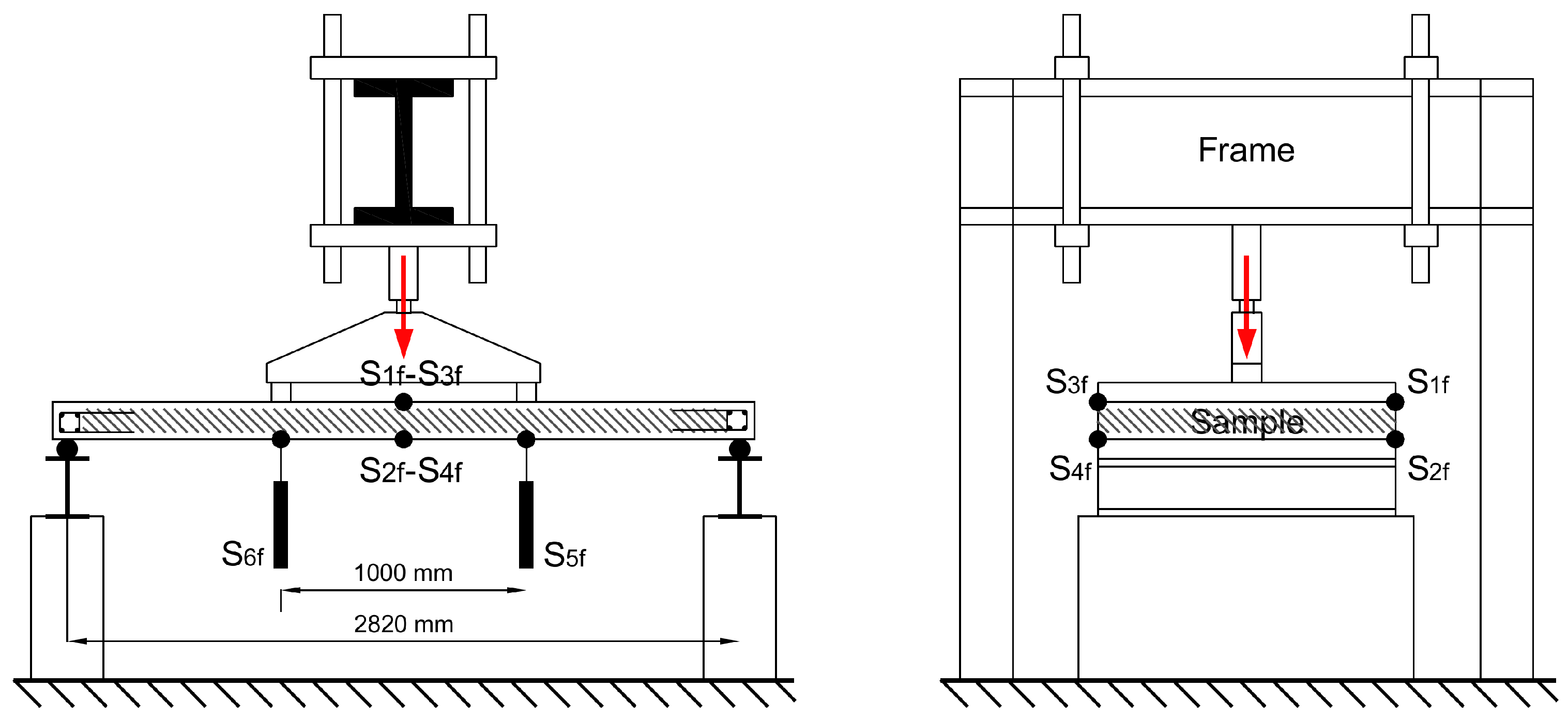
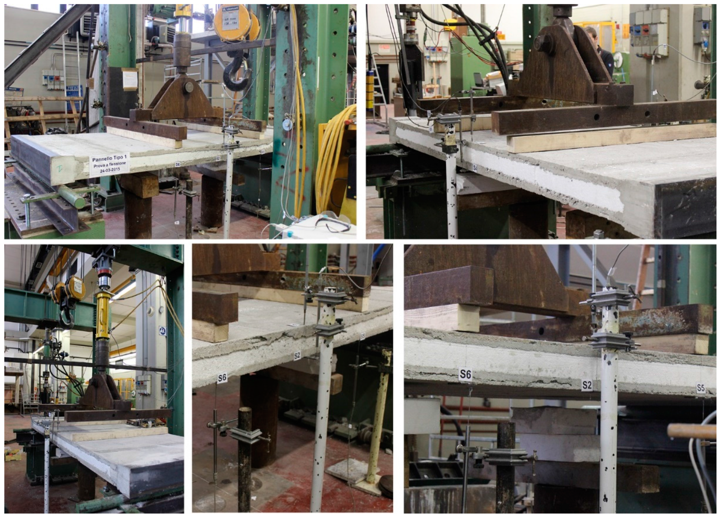
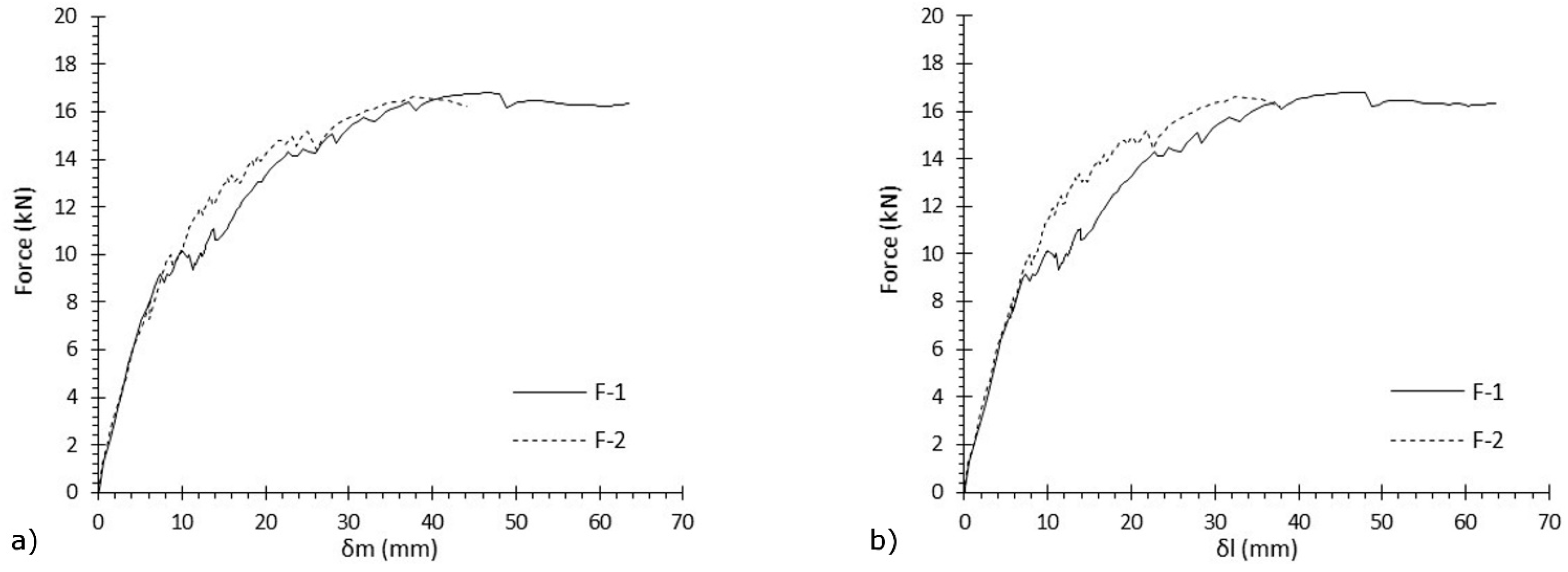
2.3. Flexural Test
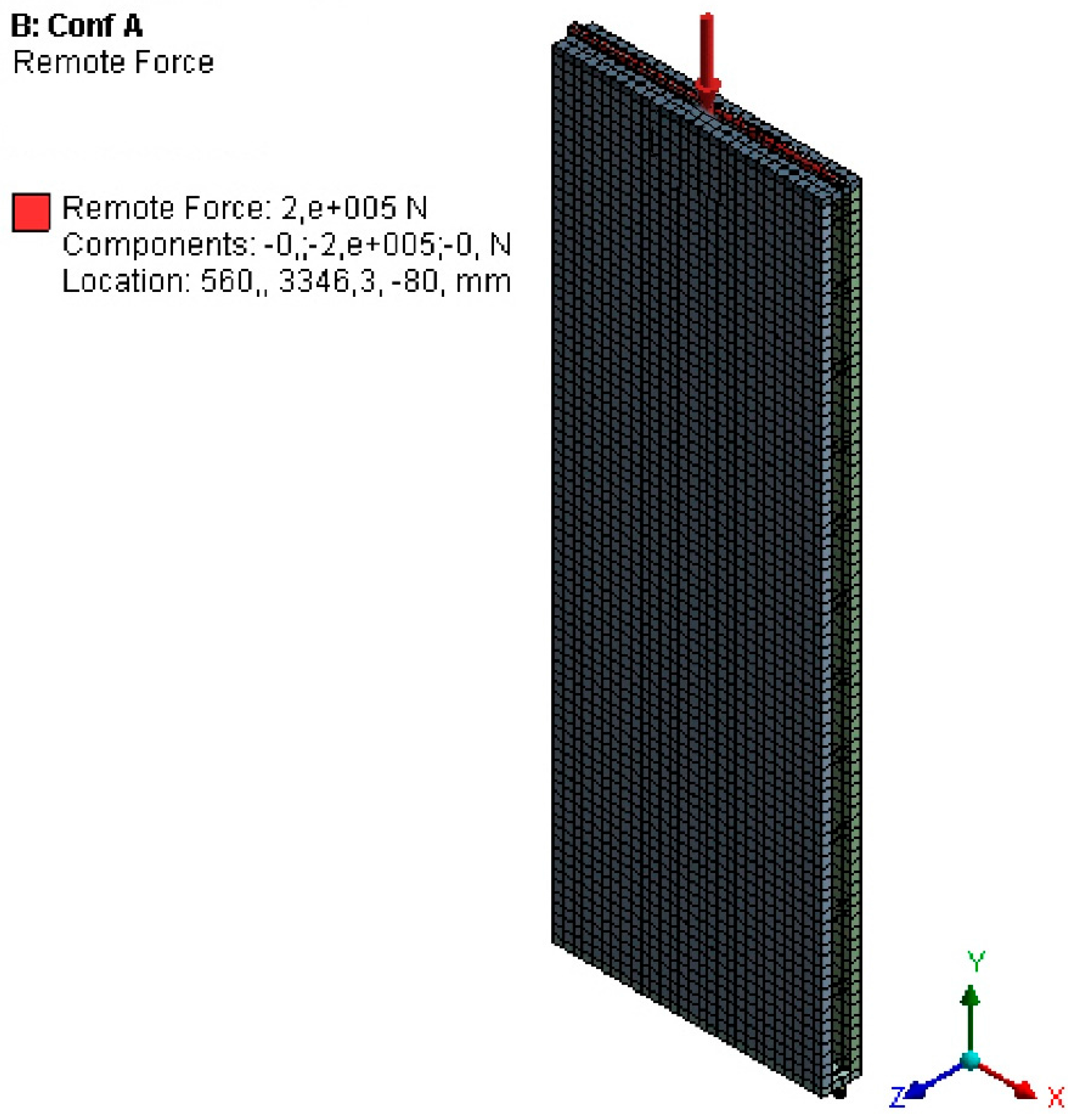
2.4. FE Design
3. Results and Discussion
3.1. Structural Performance
3.2. FE Results
4. Conclusions
Acknowledgments
Author Contributions
Conflicts of Interest
References
- Huovila, P. Buildings and Climate Change: Status, Challenges and Opportunities. Available online: http://www.unep.fr/scp/publications/details.asp?id=DTI/0916/PA (accessed on 13 March 2017).
- PCI Committee on Precast Concrete Sandwich Wall Panels. State of the Art of Precast/Prestressed Concrete Sandwich Wall Panels. PCI J. 2011, 56, 131–176. [Google Scholar]
- Dzelzbetons-MB. Environmetal Product Declaration: Precast Concrete Insulated Wall Elements. The Norvegian EPD Foundation. NEPD-400-280-EN. 2016. Available online: http://mbbetons.lv/uploads/certs/nepd-400-280-en-precast-concrete-insulated-wall-elements-gk.pdf (accessed on 13 March 2017).
- Canadian Precast/Prestresses Concrete Institute (CPCI); National Precast Cocrete Association-(NPCA); Precast/Prestressed Concrete Institute (PCI). Environmental Product Declaration (EPD) for Precast Concrete: Architectural & Insulated Wall Panel Industry Wide EPD. Available online: http://www.pci.org/uploadedFiles/Siteroot/Design_Resources/Related_Content/EPD%20Architectural%20and%20Insulated.pdf (accessed on 13 March 2017).
- Ahmad, I.; Mohamad, N.; Tun, U.; Onn, H.; Raja, P.; Pahat, B. Structural Behaviour of Precast Lightweight Concrete Sandwich Panel Under Eccentric Load: An Overview. In Proceedings of the International Conference on Civil and Environmental Engineering Sustainability (IConCEES 2011), Johor Bahru, Malaysia, 3–5 April 2012.
- Suryani, S.; Mohamad, N. Structural Behaviour of Precast Lightweight Foamed Concrete Sandwich Panel under Axial Load: An Overview. Int. J. Integr. Eng. 2012, 4, 47–52. [Google Scholar]
- Mackerle, J. Finite element analyses of sandwich structures: A bibliography (1980–2001). Eng. Comput. 2002, 19, 206–245. [Google Scholar] [CrossRef]
- Benayoune, A.; Samad, A.A.A.; Ali, A.A.A.; Trikha, D.N. Response of pre-cast reinforced composite sandwich panels to axial loading. Constr. Build. Mater. 2007, 21, 677–685. [Google Scholar] [CrossRef]
- Benayoune, A.; Samad, A.A.A.; Trikha, D.N.; Ali, A.A.A.; Ashrabov, A.A. Structural behaviour of eccentrically loaded precast sandwich panels. Constr. Build. Mater. 2006, 20, 713–724. [Google Scholar] [CrossRef]
- Gara, F.; Ragni, L.; Roia, D.; Dezi, L. Experimental tests and numerical modelling of wall sandwich panels. Eng. Struct. 2012, 37, 193–204. [Google Scholar] [CrossRef]
- Mugahed Amran, Y.H.; Abang Ali, A.A.; Rashid, R.S.M.; Hejazi, F.; Safiee, N.A. Structural behavior of axially loaded precast foamed concrete sandwich panels. Constr. Build. Mater. 2016, 107, 307–320. [Google Scholar] [CrossRef]
- Carbonari, G.; Cavalaro, S.H.P.; Cansario, M.M.; Aguado, A. Flexural behaviour of light-weight sandwich panels composed by concrete and EPS. Constr. Build. Mater. 2012, 35, 792–799. [Google Scholar] [CrossRef]
- Carbonari, G.; Cavalaro, S.H.P.; Cansario, M.M.; Aguado, A. Experimental and analytical study about the compressive behavior of eps sandwich panels. Mater. Constr. 2013, 63, 393–402. [Google Scholar]
- Benayoune, A.; Samad, A.A.A.; Trikha, D.N.; Ali, A.A.A.; Ellinna, S.H.M. Flexural behaviour of pre-cast concrete sandwich composite panel—Experimental and theoretical investigations. Constr. Build. Mater. 2008, 22, 580–592. [Google Scholar] [CrossRef]
- Fouad, F.H.; Farrell, J.; Heath, M.; Shalaby, A.; Vichare, A. Behavior of the MR Sandwich Panel in Flexure. Available online: https://www.concrete.org/publications/internationalconcreteabstractsportal.aspx?m=details&ID=56626 (accessed on 13 March 2017).
- Basunbul, I.A.; Saleem, M.; Al-Sulaimani, G.J. Flexural behavior of ferrocement sandwich panels. Cem. Concr. Compos. 1991, 13, 21–28. [Google Scholar] [CrossRef]
- Pessiki, S.; Mlynarczyk, A. Experimental Evaluation of the Composite Behavior of Precast Concrete Sandwich Wall Panels. PCI J. 2003, 48, 54–71. [Google Scholar] [CrossRef]
- Salmon, D.C.; Einea, A.; Tadros, M.K.; Culp, T.D. Full scale testing of precast concrete sandwich panels. ACI Struct. J. 1997, 94, 354–362. [Google Scholar]
- Teixeira, N.; Tomlinson, D.G.; Fam, A. Precast concrete sandwich wall panels with bolted angle connections tested in flexure under simulated wind pressure and suction. PCI J. 2016, 61, 65–83. [Google Scholar]
- Hamid, N.H.A.; Fudzee, M.F. Seismic Performance of Insulated Sandwich Wall Panel (ISWP) Under In-plane Lateral Cyclic Loading. Int. J. Emerg. Technol. Adv. Eng. 2013, 3, 1–7. [Google Scholar]
- Ricci, I.; Palermo, M.; Gasparini, G.; Silvestri, S.; Trombetti, T. Results of pseudo-static tests with cyclic horizontal load on cast in situ sandwich squat concrete walls. Eng. Struct. 2013, 54, 131–149. [Google Scholar] [CrossRef]
- Foraboschi, P. Versatility of steel in correcting construction deficiencies and in seismic retrofitting of RC buildings. J. Build. Eng. 2016, 8, 107–122. [Google Scholar] [CrossRef]
- Tomlinson, N.; Teixeira, D.G.; Fam, A. New Shear Connector Design for Insulated Concrete Sandwich Panels Using Basalt Fiber-Reinforced Polymer Bars. J. Compos. Constr. 2016, 20, 04016003. [Google Scholar] [CrossRef]
- Focacci, F.; Foraboschi, P.; de Stefano, M. Composite beam generally connected: Analytical model. Compos. Struct. 2015, 133, 1237–1248. [Google Scholar] [CrossRef]
- Kabir, M.Z.; Nasab, M.H. Mechanical properties of 3D wall panels under shear and flexural loading. In Proceedings of the 4th Structural Speciality Conference of the Canadian Society for Civil Engineering, Montréal, QC, Canada, 5–8 June 2002; pp. 1–9.
- Al Kashif, M.; Mooty, M.A.; Fahmy, E.; Zeid, M.A.; Haroun, M. Nonlinear Modeling and Analysis of AAC in-filled Sandwich Panels for out of Plane Loads. World Acad. Sci. Eng. Technol. 2012, 64, 542–546. [Google Scholar]
- Lameiras, R.; Barros, J.; Valente, I.B.; Azenha, M. Development of sandwich panels combining fibre reinforced concrete layers and fibre reinforced polymer connectors. Part II: Evaluation of mechanical behavior. Compos. Struct. 2013, 105, 460–470. [Google Scholar] [CrossRef] [Green Version]
- Foraboschi, P. Three-layered plate: Elasticity solution. Compos. Part B Eng. 2014, 60, 764–776. [Google Scholar] [CrossRef]
- Foraboschi, P. Layered plate with discontinuous connection: Exact mathematical model. Compos. Part B Eng. 2013, 47, 365–378. [Google Scholar] [CrossRef]
- De Salvo, G.J.; Swanson, J.A. ANSYS Engineering Analysis System User’s Manual; Swanson Analysis Systems: Houston, TX, USA, 1985. [Google Scholar]
- Gara, F.; Ragni, L.; Roia, D.; Dezi, L. Experimental behaviour and numerical analysis of floor sandwich panels. Eng. Struct. 2012, 36, 258–269. [Google Scholar] [CrossRef]


| Sample | Connection | Type of Load |
|---|---|---|
| A-1 | bent | Axial |
| A-2 | welded | |
| E-1 | bent | Eccentric |
| E-2 | welded |
| Sample | Connection | Type of Load |
|---|---|---|
| F-1 | bent | Four points bending |
| F-2 | welded |
| Material | Density (kg/m3) | Young’s Modulus (MPa) | Poisson’s Ratio |
|---|---|---|---|
| Concrete | 2500 | 30,000 | 0.2 |
| Steel | 7850 | 210,000 | 0.3 |
| Insulation—expanded polystyrene | 15 | 6.5 | 0.12 |
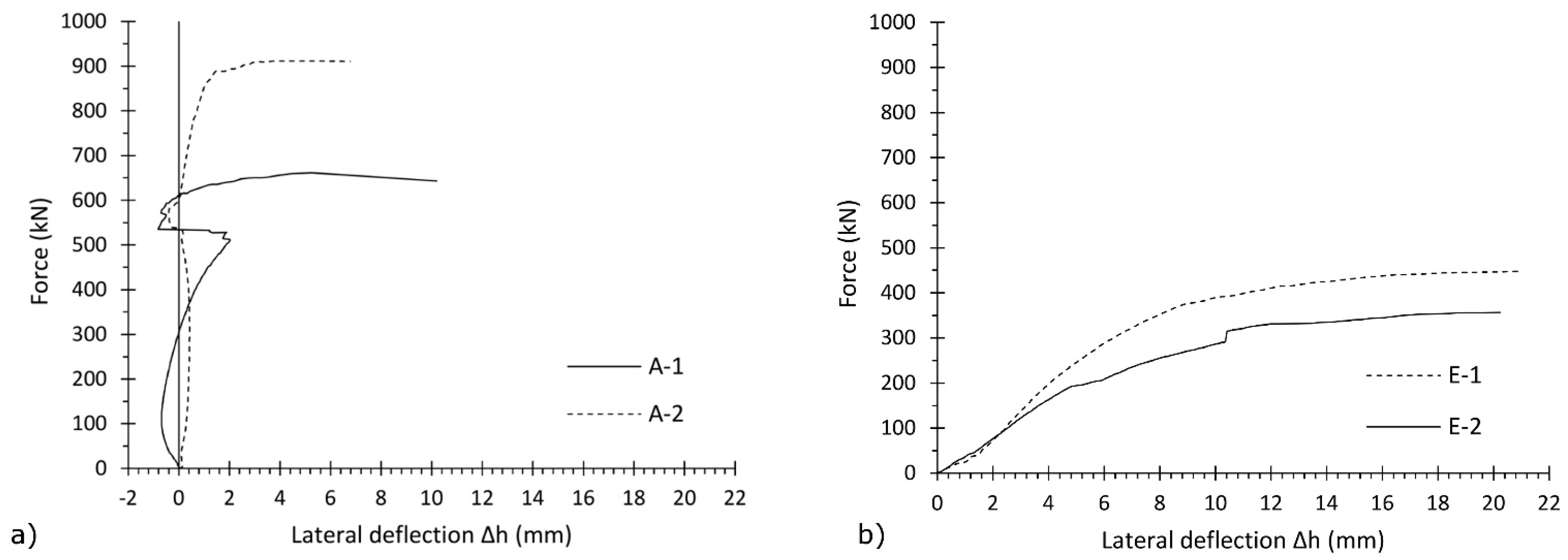
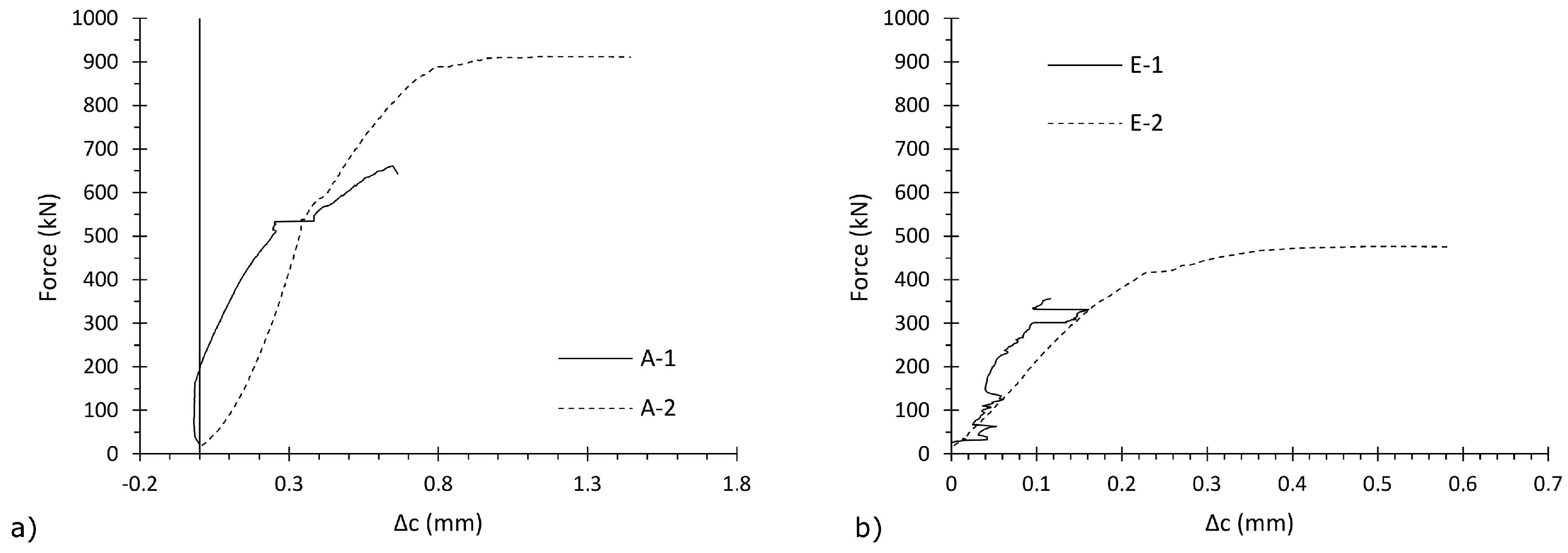
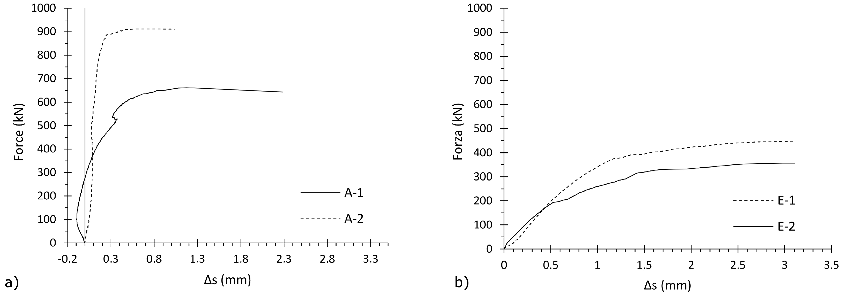
| Sample | Connection | Type of Load | Ultimate Load (kN) Mean ± Stand. Dev. | Vertical Displacement (mm) |
|---|---|---|---|---|
| A-1 | bent | axial | 661.44 ± 37.33 | 1.92 |
| A-2 | welded | 911.93 ± 45.68 | 1.64 | |
| E-1 | bent | eccentric | 356.65 ± 28.24 | 1.46 |
| E-2 | welded | 447.48 ± 30.76 | 1.75 |
| Sample | Type of Connection | Ultimate Flexural Load (kN) Mean ± Stand. Dev. | δm (mm) | δl (mm) |
|---|---|---|---|---|
| F-1 | bent | 16.82 ± 0.83 | 56.62 ± 1.21 | 49.88 ± 0.83 |
| F-2 | welded | 17.03 ± 1.27 | 50.70 ± 1.78 | 43.38 ± 0.03 |
| Configuration | Type of Load | Mesh Spacing (mm) | Stress (MPa) | Security Factor |
|---|---|---|---|---|
| A | axial | 70 × 70 | 336.01 | 2.19 |
| B | 70 × 120 | 389.72 | 1.89 | |
| C | eccentric | 70 × 70 | 357.95 | 2.06 |
| D | 70 × 120 | 420.95 | 1.75 |
© 2017 by the authors. Licensee MDPI, Basel, Switzerland. This article is an open access article distributed under the terms and conditions of the Creative Commons Attribution (CC BY) license ( http://creativecommons.org/licenses/by/4.0/).
Share and Cite
Graziani, L.; Quagliarini, E.; D’Orazio, M.; Lenci, S.; Scalbi, A. A More Sustainable Way for Producing RC Sandwich Panels On-Site and in Developing Countries. Sustainability 2017, 9, 472. https://doi.org/10.3390/su9030472
Graziani L, Quagliarini E, D’Orazio M, Lenci S, Scalbi A. A More Sustainable Way for Producing RC Sandwich Panels On-Site and in Developing Countries. Sustainability. 2017; 9(3):472. https://doi.org/10.3390/su9030472
Chicago/Turabian StyleGraziani, Lorenzo, Enrico Quagliarini, Marco D’Orazio, Stefano Lenci, and Agnese Scalbi. 2017. "A More Sustainable Way for Producing RC Sandwich Panels On-Site and in Developing Countries" Sustainability 9, no. 3: 472. https://doi.org/10.3390/su9030472