1. Introduction
It is expected that the next-generation farm based on renewable generators will be developed from clusters of various distribution sources collaborating with compensation-device applications, which could be performed in sequence by the grid operator to enhance the power-supply capability [
1,
2]. Among the various applications, an energy storage system (ESS) has been consistently utilized for handling the supply and demand issues caused by renewable sources that have unique fluctuation features [
3]. The increasing storage demand in several industrial sections has led to the development of improved features for not only a fast response capability but also for ensuring sufficient sizes for the applicable devices [
4,
5]. Furthermore, with many grids planning to configure highly penetrated wind generators, which could exceed the maximum system load, the challenges and demands of the high-end ESS applications will increase.
Since the distributed farm generation systems demonstrate variations in their characteristics owing to the unpredictable natural conditions, despite the inbuilt smoothing effect, the power profile from the farm generates considerable uncertainty in the grid operation. In the standard deviation, farm based system can achieve 50% reduction of uncertainty due to smoothing effect [
6], but further advanced solutions are still discussed with various aspect. To cooperate with even individual wind turbine, a plan for smoothing the output power of the wind power system using a BESS at the DC control section has been recently considered [
7]. The main enhancement target of the management system under study is the cooperation among connected generators, which can reliably improve the response capability when order is applied [
8]. The superiority of ESS in the electricity market has been described in terms of the smoothing effect that makes the renewable output power relatively stable in [
9,
10]. Real power management solutions for the support of active power curtailment, mainly based on pitch control to follow the order induced by the transmission and system operator (TSO), are necessary for an electrically sensitive grid. Normally, a generic controllable wind system considers only the pitch angles of the blades to handle the fluctuating and excessive power profiles. However, mechanical stress accrues in the blade if the pitch-angle control operates at a rate fast enough to mitigate short-term fluctuations [
11,
12]. These power curtailment abilities, in terms of response accordance, are expected to be improved by the support from the storage received through appropriate operation strategies. Several energy storages (including batteries) are composed with inbuilt complementary modes to respond to grid requirements by focusing on the power fluctuations of renewable sources [
13]. Most importantly, in the case of implementing both limit options (curtailment and compensation) along with renewable generators, storage devices have to be integrated with appropriate specifications. In order to maintain these combined systems, electrical approaches based on both system order and appropriate ESS design are required.
Conventional applications for grid support have focused on the frequency responses of traditional pumped hydroelectric or compressed-air energy storages [
14]. However, due to the geographical constraints at specific sites, large-scale ESSs have been developed and utilized in several microgrid systems. To achieve advanced frequency management within a microgrid, a number of control schemes including hierarchical control were introduced in [
15,
16,
17]. These studies suggested the possibility of using ESS configurations for frequency control in small-scale power systems requiring management of multiple distributed generators and active loads. In previous researches, however, the ESSs were generally composed separately, which meant that there was an AC section between two different power-conversion systems (PCS) for ESS-renewable sources and that the utilized topologies were focused fully on their own independent DC sections behind inverter devices [
18,
19]. These plans could support reactive power for the rate voltage level at the connection point and it helped the ESSs perform power handling processes with stable operating conditions [
20]. In case of DC-integration based on multi-sources, however, previous predictive control methods could not provide a solid ESS response owing to the voltage variations caused by the power flows from various sources. In particular, since DC-based renewable generators could impose unpredictable profiles on the ESS operation processes, specific supporting strategies to manage the transient situation of the power system were demanded to cover these issues.
Typical DC based sources, PV and tidal, have currently been designed to be cluster with some wind generators as described in [
21,
22]. Lately, offshore systems for increasing electrical generation efficiency, by composing many generators at designated geographical areas, have been continuously studied and efforts have been made to improve the availability of integrated electrical subsystem for power transmission [
23]. The interests in researching the existing distributed sources and composing a combined generator system that is suitable to reduce the building cost at the offshore region have been increasing. The wave–offshore hybrid generation system, which is currently designed as a single system, is composed to easily integrate various sources and have possibilities to improve the electrical generation capacity using additional wave generators. The designed structure currently obtains a certification regarding the reliability issues of structural composition [
24]. In the current state of the mentioned generation system, wind turbines which are based on permanent magnetic synchronous generator (PMSG) and grouped wave generation system which is based on permanent magnetic synchronous linear generator (PMSLG) have been considered as main power sources and equipped on one offshore platform, sharing required electrical equipment. As the electrical system has to be focused on operator’s demand, additional controllable applications have been studied. However, the specialized application has not been progressed.
In this paper, a voltage considered ESS compensating plan is proposed to perform the output determination for a megawatt (MW) class AC/DC combined generation system by focusing on the demands of the utility grid. The whole management process is formed based on power flow analysis for DC system and it deals with controllable elements that can reflect connected devices. The verification process for designed method is progressed with the electromagnetic transients with DC analysis (EMTDC) software tool. The ESS model composition including control topologies is implemented in case studies. The designed simulation case studies are focused on appropriate operation of an active power-control scheme in accordance with the reference signal from the TSO.
2. System Description
When developing an ESS-combined system utilizing a common DC link with a number of generators, a relevant compensation strategy based on the electrical composition should be formulated to consider the internal voltage conditions—the offshore-based combined generator structures normally have DC sections that are almost 150 m long [
25,
26].
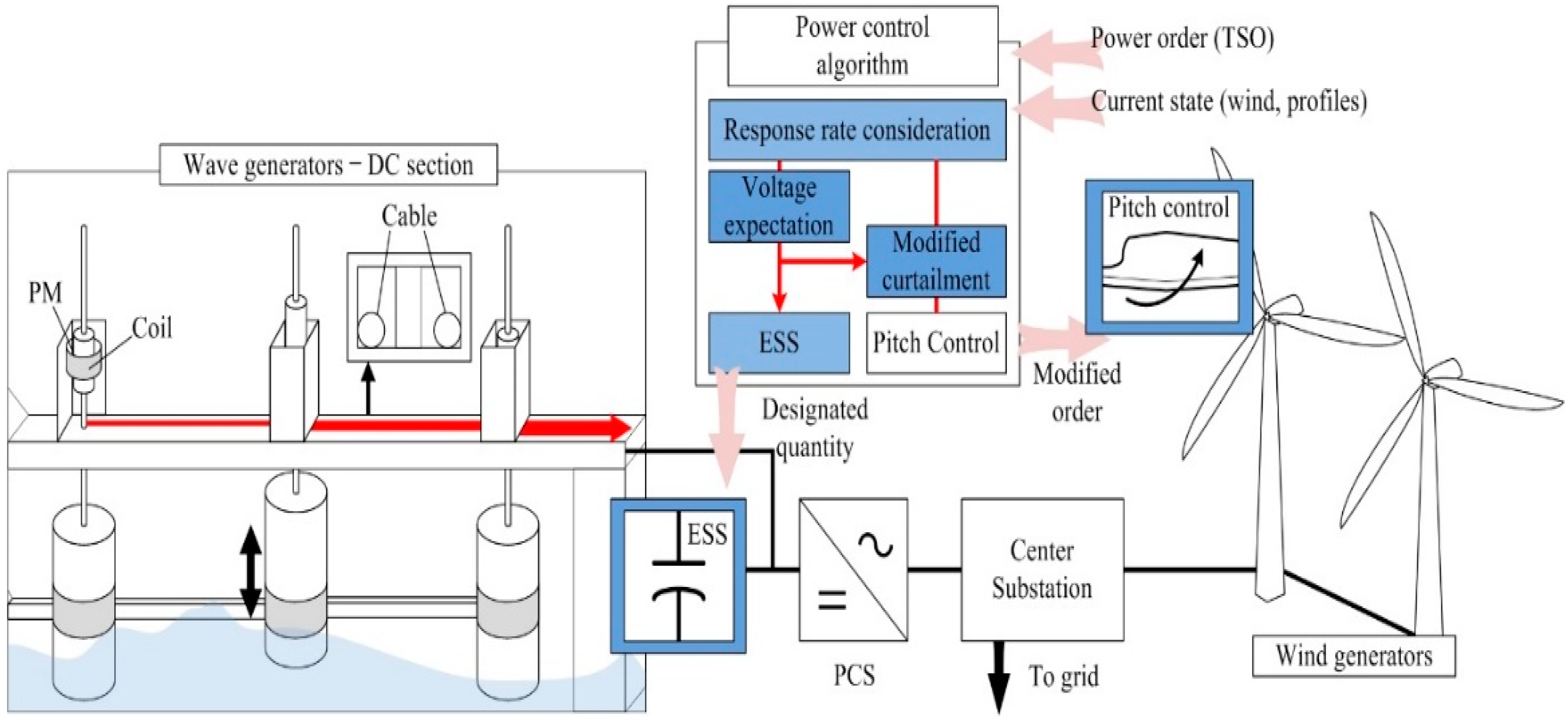
Figure 1 shows the conceptual control plan of the proposed method. The profiles from the DC-based resources are transferred to the connected power system via an internal conversion device. The ESS, as a compensation device, will be integrated in the common DC link with its own DC/DC converter. The power flow from the DC-based generators (PV or wave) has to be passed through the connection point of the ESS because such compensation devices should be located at the front of the PCS [
27]. This flow makes the integrated storage device directly affected by electrical condition in terms of voltage level, which is one of the main reference values in the control process. In this study, the main topology is consist of a system that stores the excess output power (over the reference signal) and a bidirectional PCS that is composed for handling the entire output power of combined generation system. The power-control algorithm deals with both mechanical pitch control for the wind system and electrical control for the ESS device. By calculating the order for ESS accurately, the operational load of pitch control can be mitigated and an option for further power saving can be composed. Including utilized DC network characteristics, DC power flow analysis will be discussed in this section. Before that, basic system descriptions will be treated in the following sections.
2.1. AC/DC Combined Resources
The existing voltage source converter (VSC) based farm structure is usually established on an AC generation system which means the generated AC power has to be passed DC section by utilizing own conversion device. Therefore, the profile can be involved a large switching loss compared with other DC based distribution network as described in [
28,
29]. Due to this issue, there are several studies for DC farm topologies to reduce the efficiency problem in power supply [
30]. In addition, conventional DC based sources have extended available farm scale in terms of the number and level of the classified voltage. These trends build a hybrid concept in terms of operation environment which has an advantage of not only the structural efficiency of transmission system but also the power utilization [
31]. When composing a combine system with the wind-energy systems in the offshore regions, in particular, the tidal linear generator is being aggressively considered as a suitable cooperating device owing to their effectiveness and popularity [
32].
The proposed scheme in this paper is focused on previously composed wave–offshore generating structure. The shared platform is currently being composed and has an AC/DC hybrid electrical structure as it is based on several wind and wave generators. The platform has been evaluated as suitable for ESS application because it has sufficient place for handling various sources. When the ESS is attached to the structure, the device will be located in central subsystem, and have to be managed to improve the reliability of following the orders of the grid operator. To manage the order with ESS, the DC structure of the system is a major consideration because each generator in this section is not utilized as a controllable unit by operator. The power control plan except for tripping units for supporting previous mechanical controller can be tested by dynamic movement of wave system (it can be hired in other hybrid generation form such as PV-wind).
The total capacity of the wave–offshore combined generation system can be improved than that of the single renewable source, and it demands an advanced curtailment scheme for maintaining the grid stability which is a main consideration of TSO [
33]. Therefore, such systems should first consider mechanical curtailment scheme with the pitch-controller for the wind system but additional applications are still required. The ESS application, which is normally applied in DC section, is also being taken into account due to its usability; however, the generated power flow through the long DC section could lead to an unstable voltage condition at the interconnection point. As a various power generation including compensating device is expected in this common DC link, advanced technology will be required based on DC network analysis for maintaining the system performance.
2.2. DC-Link Characteristics
2.2.1. Bipolar-Type DC Network
Conventional DC-integrated sections are composed using the unipolar-type or bipolar-type inverters as described in [
34,
35]. Since every component in the unipolar-type is connected directly between the “positive” and “negative” conductors, the number of power electronic devices utilized can be reduced considerably. In the previous configurations, therefore, unipolar-type DC sections were composed to reduce the electrical configuration cost. However, nowadays, the power-conversion capacity is higher than that of the previous electrical transfer systems; therefore, the preference for bipolar-type inverters is increasing. The transmission capacity of the bipolar-type is greater than that of the unipolar-type at the same voltage level, and it can provide a wider range of voltage levels. As the required transmission capacity has been growth comparing with that of previous electrical grid, this topology has further advantages as described in [
36], and also seems to bring benefits for low voltage based distribution network [
37,
38]. Furthermore, the cost reduction of the power electronic devices derives the bipolar-type configuration because the system offers larger transmission capacity and has many advantages [
39]. In terms of voltage stability, VSC based converter devices with high capacity also have strong point of extracting demanded reactive power to support connected utility grid [
26]. A bipolar-type DC distribution network is being considered in composing and analyzing process of the DC based wave-ESS application.
2.2.2. DC-Based Generators
Since a few of the renewable sources utilizing multifeed systems for reducing construction costs use directly integrated capacitor devices, dynamic performance according to the generated current flow causes continuous voltage variations. This paper mainly considers the full-converter-type wind generator and the PMSLG for the wave system as the main devices for the proposed verification process. It generates active current according to the applied environmental factor and the generated profile will be transferred to the utility grid by utilizing own conversion devices [
40,
41]. The wave generators composed at the combined system, as mentioned above, are designed to adapt a multifeed topology [
42]. Generic generation capacity in the wave-generation system is slightly lower than that of the wind turbine, and it allows an electrically shared section in the point of interconnection for several generators. Owing to its capacity, in addition, the wave system does not consider additional curtailment methods in the general state and normally follows the maximum power point tracking (MPPT) option. If we consider other controllable devices like variable resistance or storage system, the DC link is suitable for those combined systems. When estimating the PCS for composed system, the demanded capacity calculation can consider optimized power control pattern in the DC network. Therefore, the required PCS capacity for combined system can be reduced by focusing on the expected peak supply profile of the subsystem (the PCS for AC subsystem should consider aggregate value of connected devices) [
43]. This method can derive the optimized PCS utilization for the combined generation system in order to replace the inverters in each connection points. Furthermore, these results can contribute to the reduction of the number of power electronic devices, which can affect the total capacity and cost of the rectifiers required in the DC generation system. Therefore, the proposed scheme will discuss the profile management plan while maintaining the voltage level for each DC section to ensure that all combined sources can follow both the charging and discharging orders from the operator.
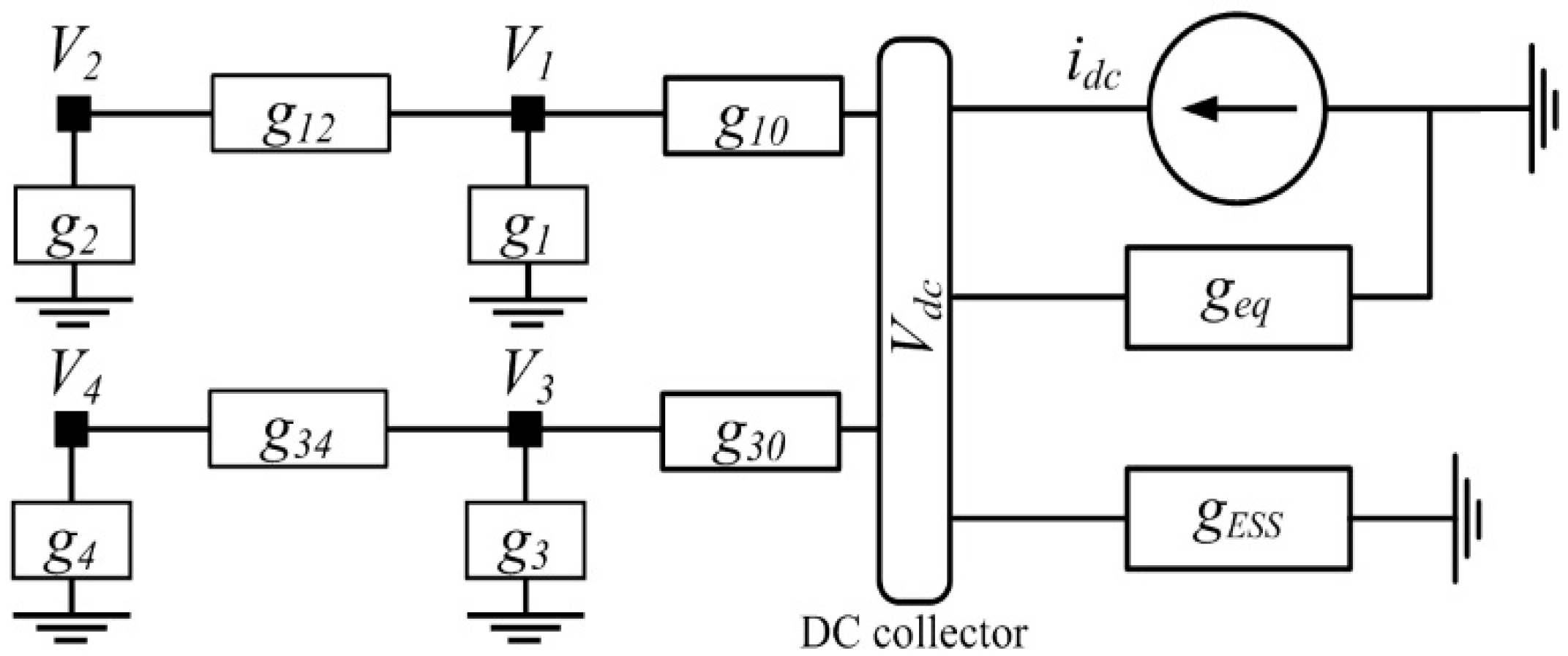
Figure 2 presents the integrated devices in the target combined system with DC power. In this system, each PMSLG that extracts power from offshore is interlinked with a common integrated part. Through DC voltage control of the grid-side inverter, the entire system can transfer the generated power to the utility grid. As described in the figure, general ESS topologies are composed based on a single connection. Therefore, the DC voltage can be directly utilized in the reference-generation processes. The proposed combined system considers equipping a supercapacitor-based ESS with the previous DC network, and a fast calculation for the real-time control signal is required. Before handling the voltage signal, a general power-flow analysis should be conducted. The injected power flow, which is highlighted with the red arrow in the figure, can be represented by the sum of each generator’s profile and the incurred sectional loss as follows:
where
Pwave is the total output power of the wave generators,
Pn is the output power of the
nth wave generator,
Ploss is the loss in the cable components, and
N is the total number of wave generators in the farm. The sectional loss can be defined as follows:
where
Pnn+1 is the real power that flows from bus
n to bus
n + 1,
rnn+1 is the resistance between bus
n and bus
n + 1, and
Vn is the bus voltage magnitude.
The PMSLG-based wave generator extracts real power according to the magnetic variation generated due to the vertical movement of connected buoy. Similar to the power production by wind turbine, the applied converter utilizes the designed curve for power coefficient. The linear generator chooses the power point within the operational range to extract maximum available power. There is no curtailment option in the linear-based generator, and every integrated generator has to follow the MPPT control mode if it is not utilizing additional compensation solutions. This paper considers the ESS application in the DC link as a power suppliable device. If the extracted output power of the combined generation system exceeds the designated order by the operator, the ESS is activated to support the pitch controller based on the previously designed mutual curtailment plan. Therefore, we have to set the total DC flow as a fixed value and utilize it in the entire circuit-analysis plan for the process designed by expecting voltage fluctuations as described in Equation (3). The DC current flow also has to be set, by using the ordered quantity, for utilization in the voltage-analysis process, as shown in Equation (4):
where
Pdc is the real power reference for the DC system,
PESS is the referred quantity for storage,
Sdc–dc is the capacity of the DC converter for the storage system,
idc is the current flow at the inverter, and
geq is the equivalent admittance of the PCS.
As a number of generators are expected to be composed into a single system, the DC-side voltage variation will be completely dependent on the output profile of the wave generators. When the operator has to handle the applied ESS for charging or discharging, the consideration about induced voltage variation have to be precise.
2.2.3. ESS Application
An ESS utilization for renewable energy sources should not only consider the voltage conditions at the connection point but also restrain the output profile in accordance with the order from the system operator. In general, the ESS in an industrial power system has a standardized system design, which is connected to a point of common coupling (PCC). It is composed for supplying stored energy to connected utility through individually composed converter, which is for converting DC power. The voltage-focused solutions in previous research utilized the specified voltage value as a limitation signal, which was used to decide whether the ESS was attached or detached to the target network.
Figure 3 describes these concepts with a flywheel-based ESS solution, which employs a superconducting rotational mass [
41]. This application usually depends on a bidirectional controller to control the flow and decide whether to charge or discharge by sensing the DC-section voltage. The controller operates the ESS at voltages outside a designated range of voltage. That is, the ESS absorbs energy when the voltage is higher than the upper limit and stores energy when it is lower than the lower limit. Within this topology, the controller manages the voltage level strictly with in the designated range but the transferred power at the ESS cannot be defined as a specified value as illustrated in the figure. On the other hand, the proposed plan stores the accurate real power quantity by using it as a reference value rather than the voltage signal. A bidirectional power-conversion system is utilized into the ESS topology with focused on designated power and related modified values.
The ESS has to consider measured generation profile, and limit based on the applied PCS power capacity. The output profiles of each system can be represented as shown in Equations (5) by using power flow at PCC.
where
PPCC is the power flows at the PCC, and
PWT is the wind power output. The constraint in the limit process can be defined as follows:
where
Spcs is the power-conversion capacity of the main PCS, and
Qpcs is the reactive power profile of the main PCS.
The designed ESS operation is focused on allocating the stored surplus power on the power demand situation, which is predicted by state analysis. Both charging and discharging condition can be represented with a single equation as follows:
where
Pref is the designated order of the entire generation system. Under the constraint section, the ESS compensating operation is required, and the induced control signal depends on the previous state. Both charging and discharging signals have to consider utilized capacity as a constraint, as shown in Equation (8).
where
SESS is the power-conversion capacity of the converter for ESS. The ESS mainly responds to the real power gap between the generated power and the demanded order. To confirm the power consumption, the state of charge (SOC) of the ESS should be checked during the simulation process. The pre-phase SOC should be considered at every second. The SOC of the ESS is described as follows:
where
EESS is the electrical energy calculated by
PESS(t), and
Emax is the maximum electrical energy of the ESS. The ESS control scheme is applied according to the presence of power profile, and the SOC is used as the main control value in the scheme.
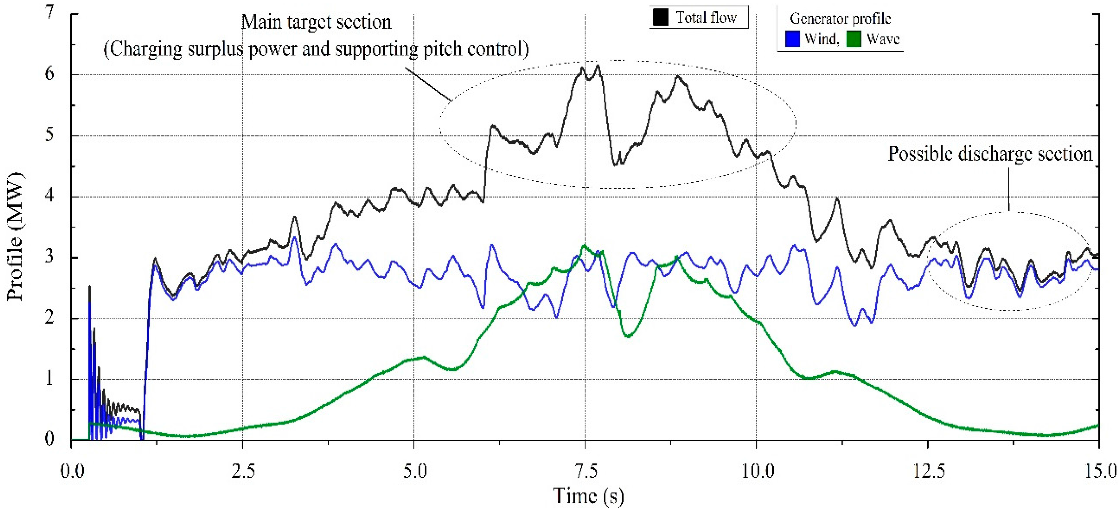
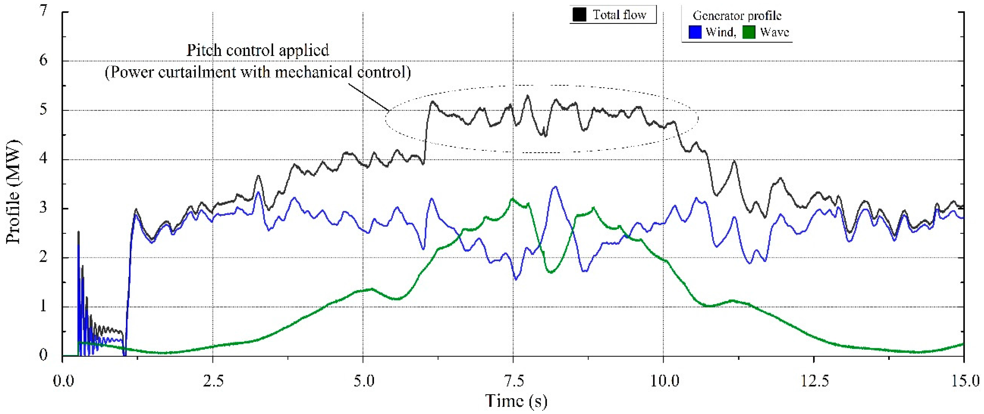
In summary, the wind turbines basically follow the MPPT. However, in the case of excess active power in comparison with the load demand, active pitch control is used for sufficient wind velocity to shed off the aerodynamic energy by turning off the blades. When the power from wind turbines must be curtailed using pitch angle control, the amount of charging quantity is firstly calculated to modify the pitch angle control. The discharge condition does not help the pitch controller directly. Nevertheless, to handle the operating condition of ESS continuously, it should be considered while system operation.
2.3. PCS Control
2.3.1. Real Power Control Scheme
The natural power captured by the generator depends on its power coefficient, which is given by the statistical data. The mechanical systems of a PMSG and PMSLG are composed considering previous discussions [
44]. The real power in a PMSG is obtained by differentiating the power coefficient, which is a function of both the tip-speed ratio and the blade pitch angle. Within the available range of pitch angles, the generator-side converter for turbine selects specified power point as a control signal to extract the most of an available power. When the rotor speed goes beyond the rated speed of the wind turbine, the pitch controller is activated to reduce the power extracted from wind. As mentioned above, the PMSLG extracts the profile for each environmental factor and the power has to be transferred to the utility grid through common DC cable. Both generation systems utilize a three-level neutral point clamped (NPC) voltage-source converter [
45]. Each rotor-side convertor follows the MPPT control independently, and the DC voltage controller that is located in the grid-side convertor for transferring real power can be represented as a single equivalent circuit for system modeling including the pulse-width modulated (PWM) conversion process.
The aim of this paper is an appropriate power compensation process that can generate a positive effect in the transient response of the power curtailment-compensation processes. The DC current can be represented by dividing the generated power with the DC voltage, as shown in Equation (10).
where
idc1 is the calculated DC current at the rotor side,
vdc is the DC voltage in the capacitor bank. The grid-side DC current can also be obtained in the same manner, and the voltage-variation signal is generated by an integrator using the differential value between the DC currents on both sides, which is adopted as shown in Equation (11).
where
vdc is the DC-link voltage,
Cdc is the value of the DC capacitor,
idc2 is the calculated DC current at the grid side. The power controller of each PCS should deal with the follow-up control structure for the reference current. In order to extract the current reference signal correctly, the proposed ESS controller adopts an additional control block to improve the signal-generation accuracy.
2.3.2. DC Controller for Wave System
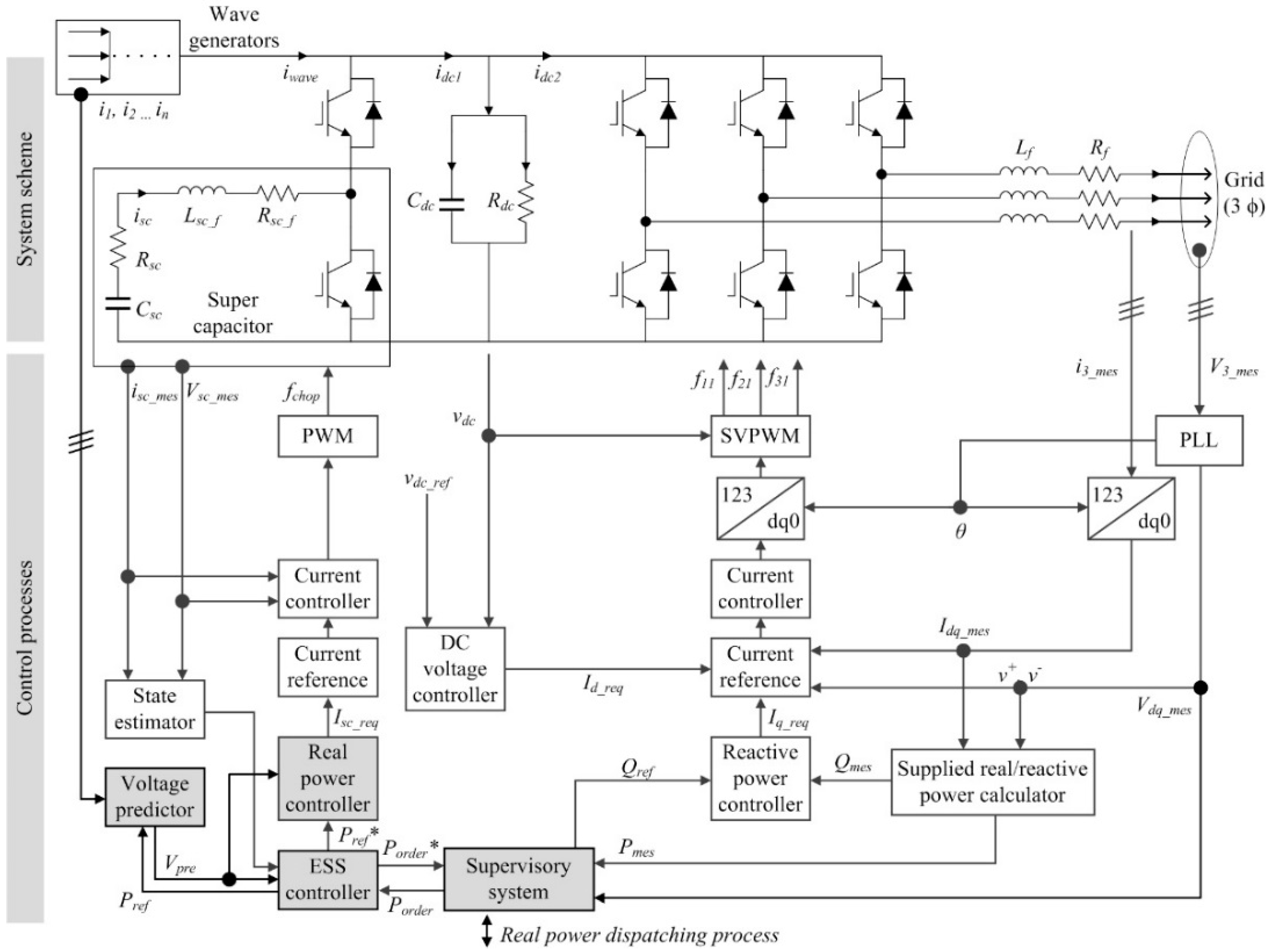
A detailed switching analysis of the ESS-combined generation farm has been studied in this research.
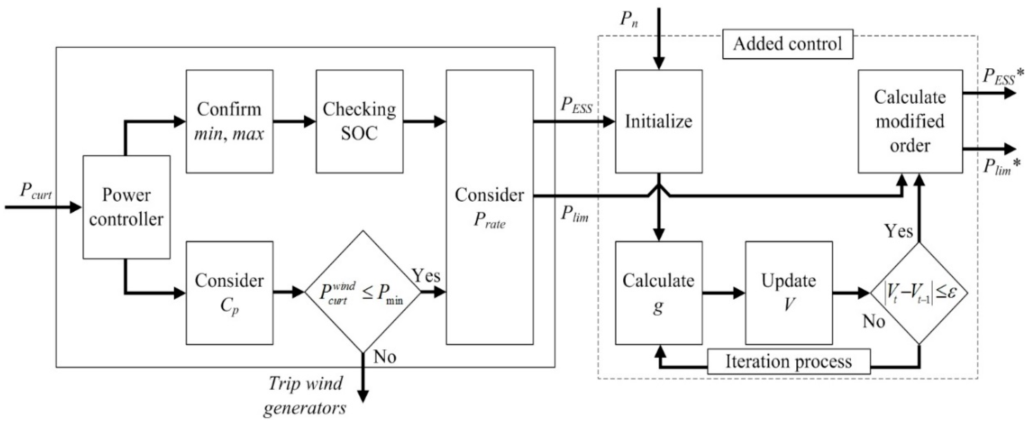
Figure 4 shows the DC-section structure of the generation farm and the related control scheme. A supercapacitor (SC) storage system is described in the structure and is expected to be connected to the grid through the power-conversion system including the boost chopper devices (The SC in this paper was designed by based on equivalent sources to have general characteristics in the aspect of the power, and response time). Along with the DC–DC converter for the storage system, the composed wave system is also directly attached to the DC link. A parallel current flow will be imposed in this section, and the autonomously measured values are used for the voltage predictor as highlighted in the figure.
The measured DC voltage is used in the grid-side converter controller, and the grid side controller (real power control for PCS) is independent from the real power control flow for the DC power profile management section (including ESS). These control flows are caused by composing the grid-side converter with a rotor-side convertor separately to follow the MPPT processes. Since the ESS has been composed based on single system, the real power command for the ESS can ignore the voltage-change prediction process. The real power controller, including the ESS-management system, directly uses the calculated voltage value to decide the final reference signal for the current controller. Finally, the supervisory system can receive the modified value as an electrically controllable quantity and handle the mechanical curtailment value for responding with the system operator.
The modification process mainly applied in the reference-calculation process is included (highlighted blocks in gray) in
Figure 4. In summary, the final modified controller updates the real power order and exchanges the modified value with the upper management system. The figure describes the d–q transform of the three-phase variables and applies the decoupled double-synchronous reference-frame phase-locked loop (PLL) method, which extracts the positive sequences at the measured values [
46].


