
Micro-Encapsulated Phase Change Materials: A Review of Encapsulation, Safety and Thermal Characteristics


Abstract
:1. Introduction
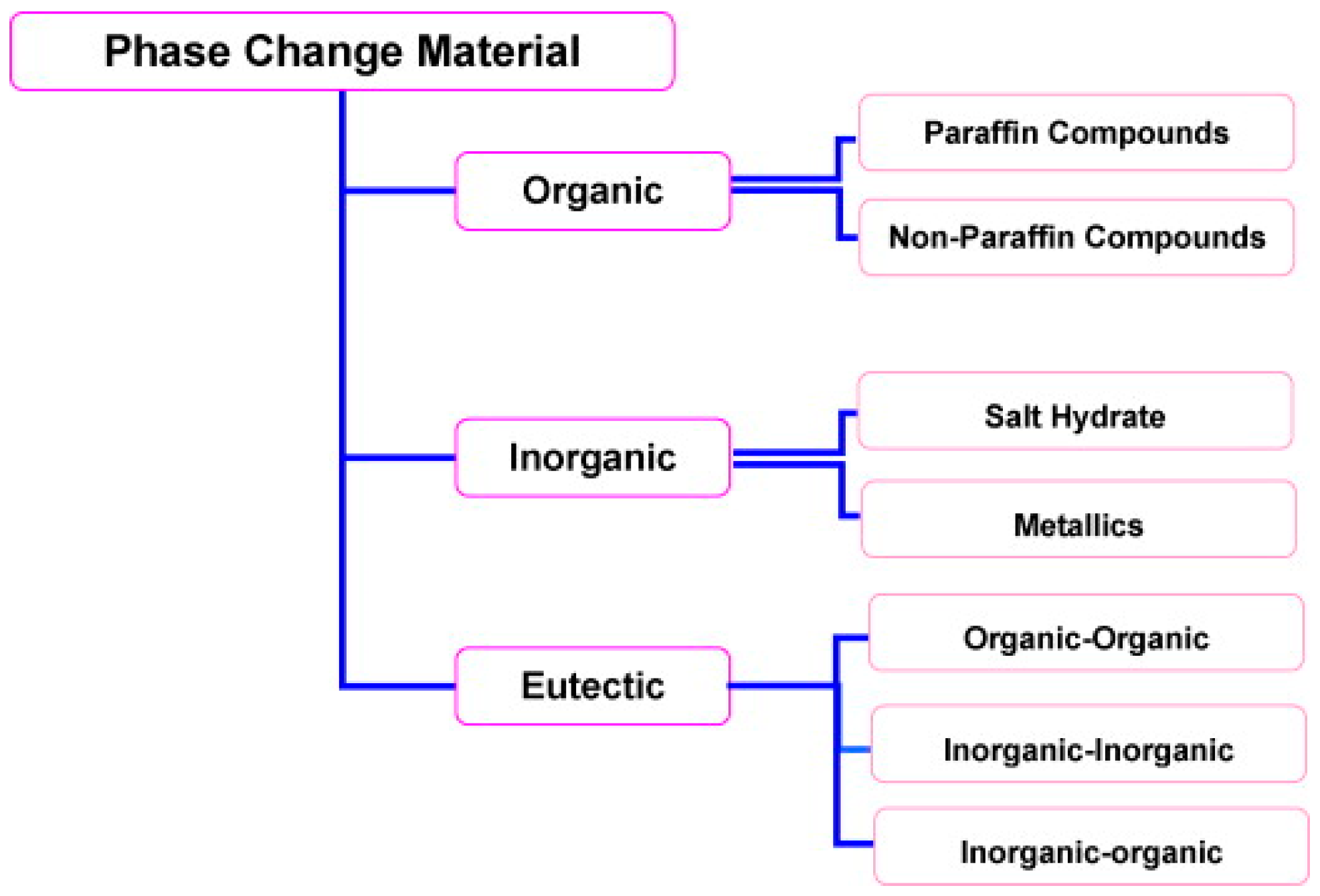
2. Optimum Core (PCM) and Shell (Encapsulant) Materials
2.1. Paraffin Waxes
2.2. Organic Non-Paraffins (Fatty Acids)
2.3. Salt Hydrates
2.4. Low Melting Point Metals and Alloys
2.5. Commercial PCMs
3. Methodologies of Microencapsulation of PCMs
3.1. Chemical Processes
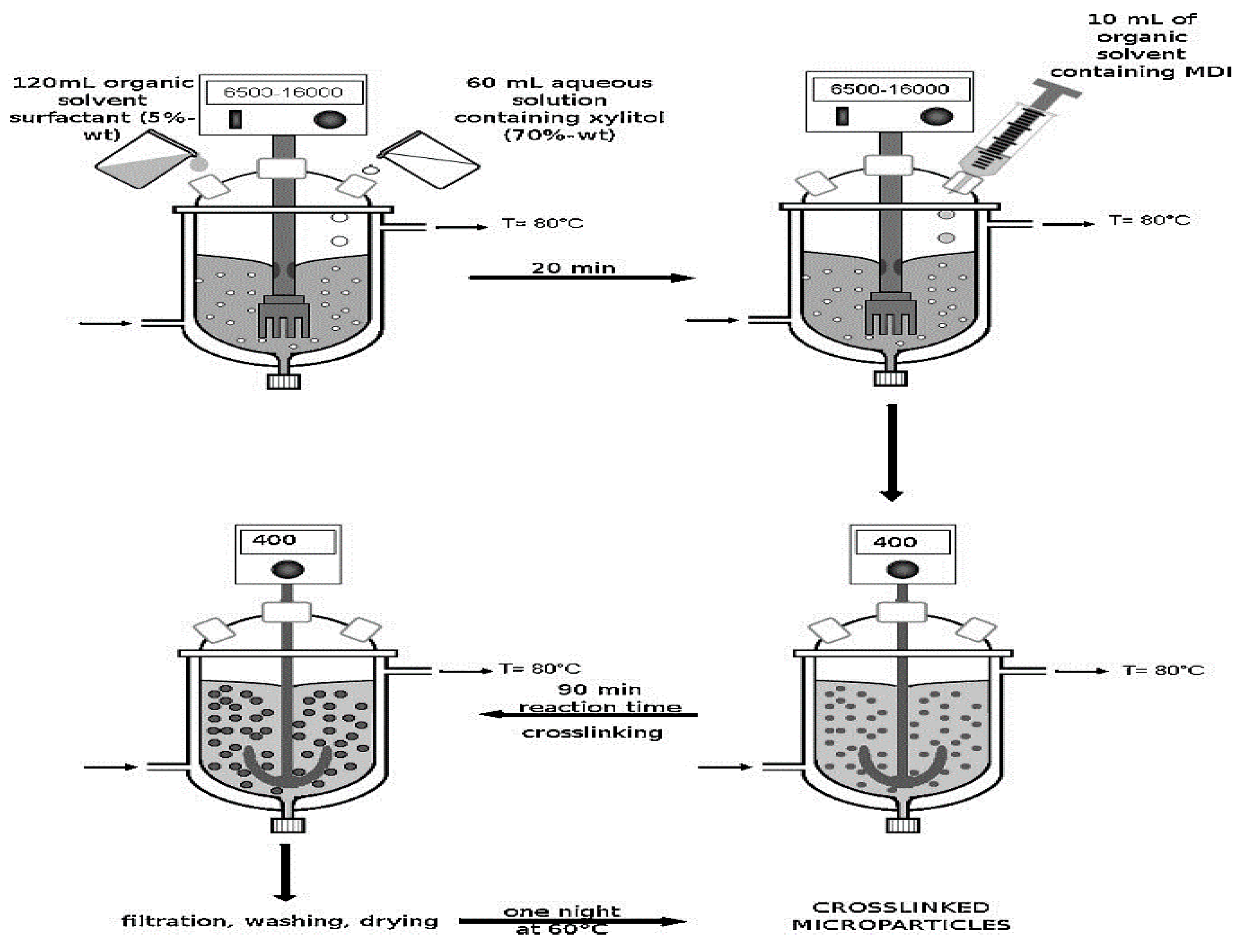
3.1.1. Interfacial Polymerization
3.1.2. In-Situ Polymerization
3.2. Physico-Chemical Processes
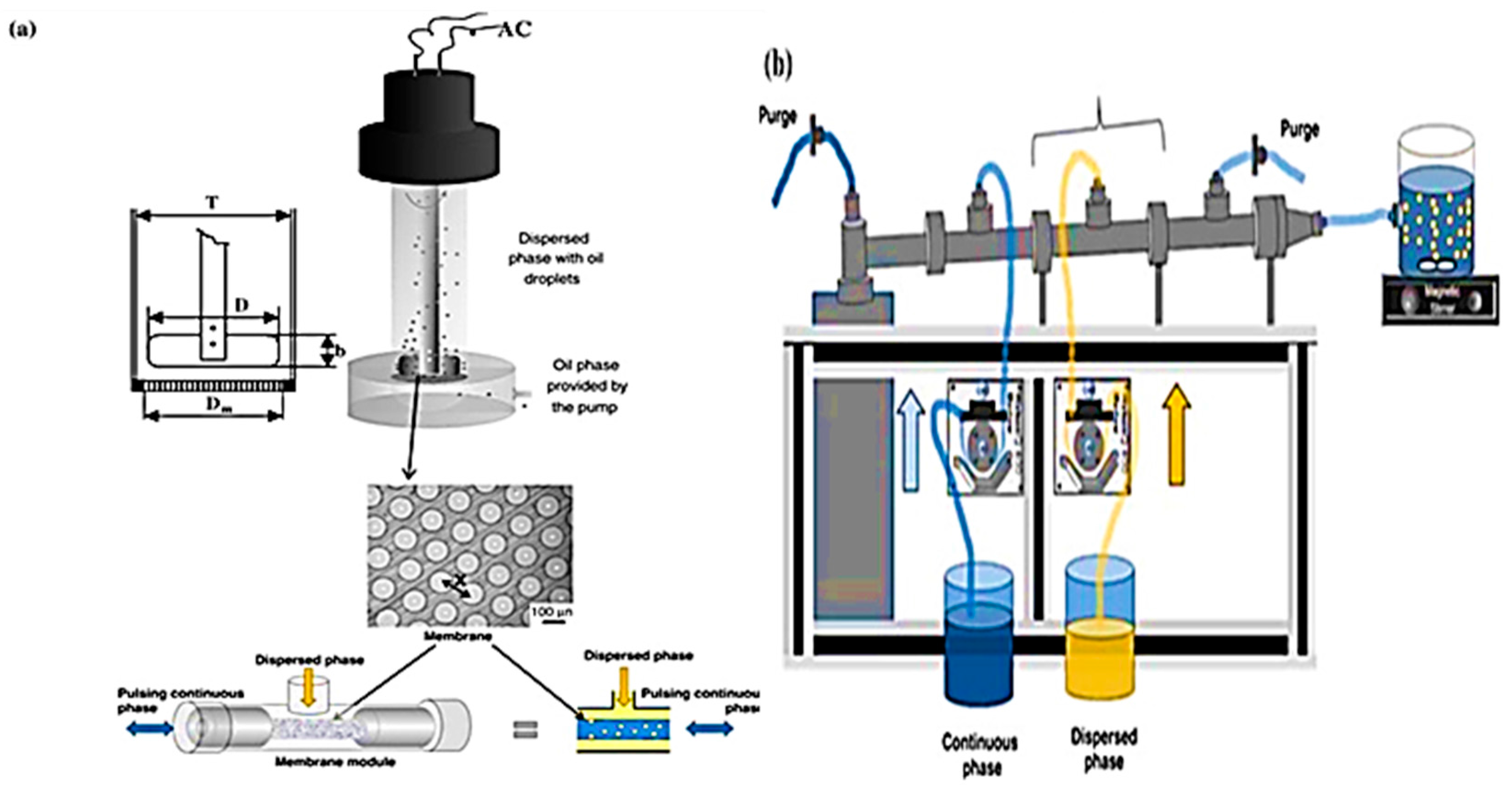
3.2.1. Coacervation and Phase Separation
3.2.2. Sol–Gel Encapsulation
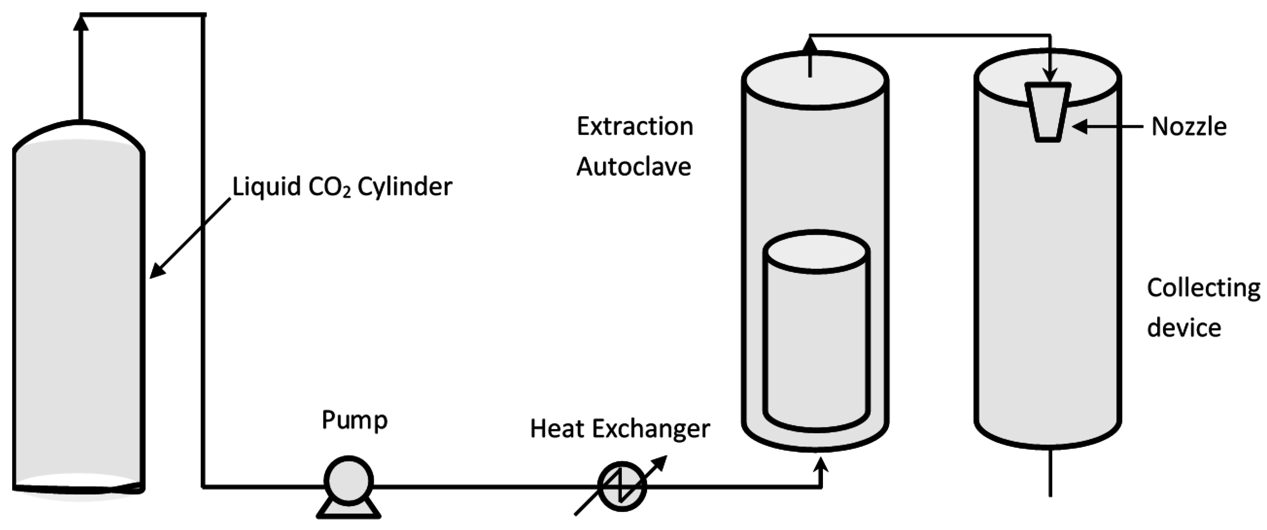
3.2.3. Supercritical CO2 Assisted Microencapsulation
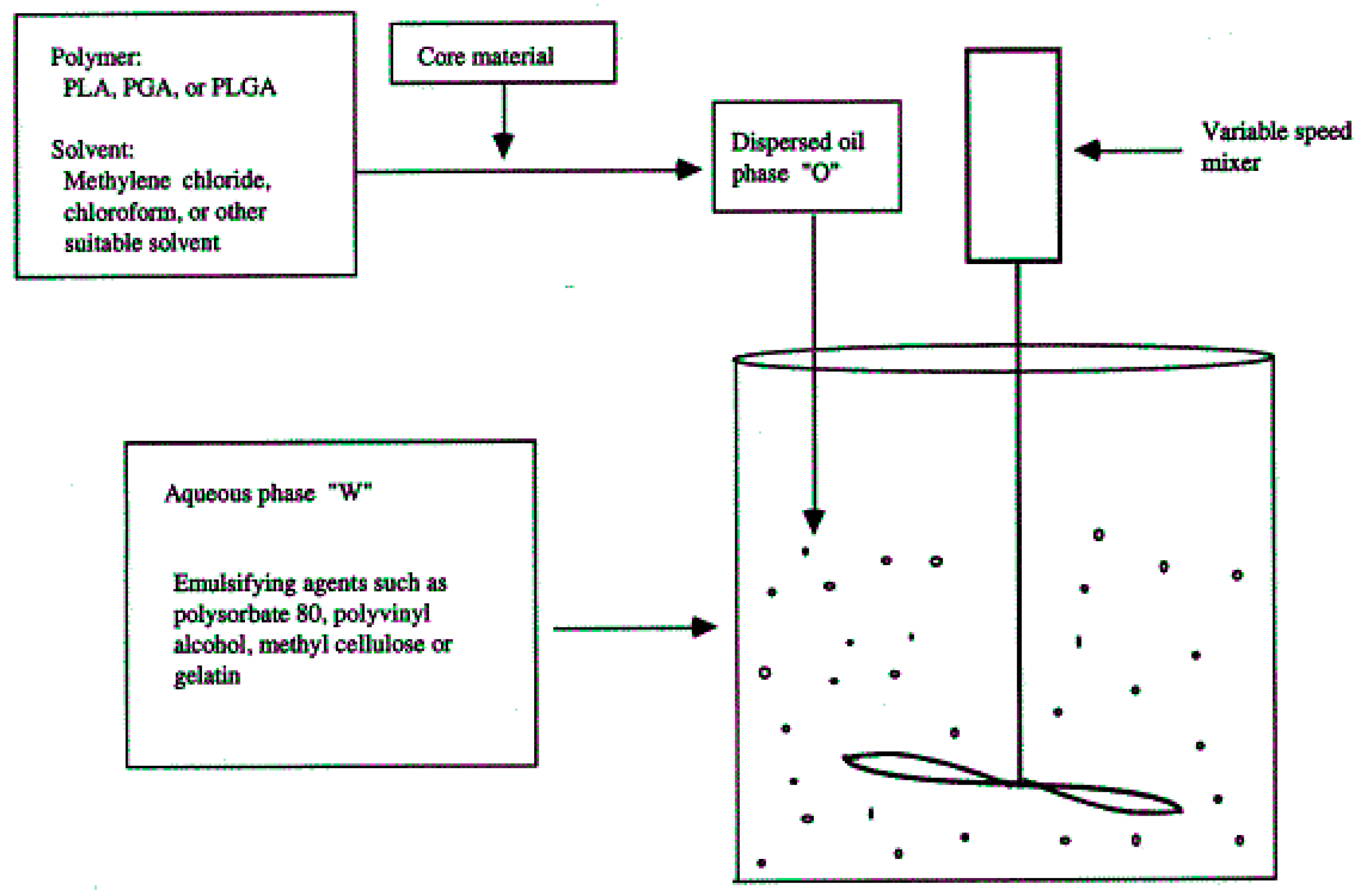
3.2.4. Solvent Evaporation
3.3. Mechanical Processes
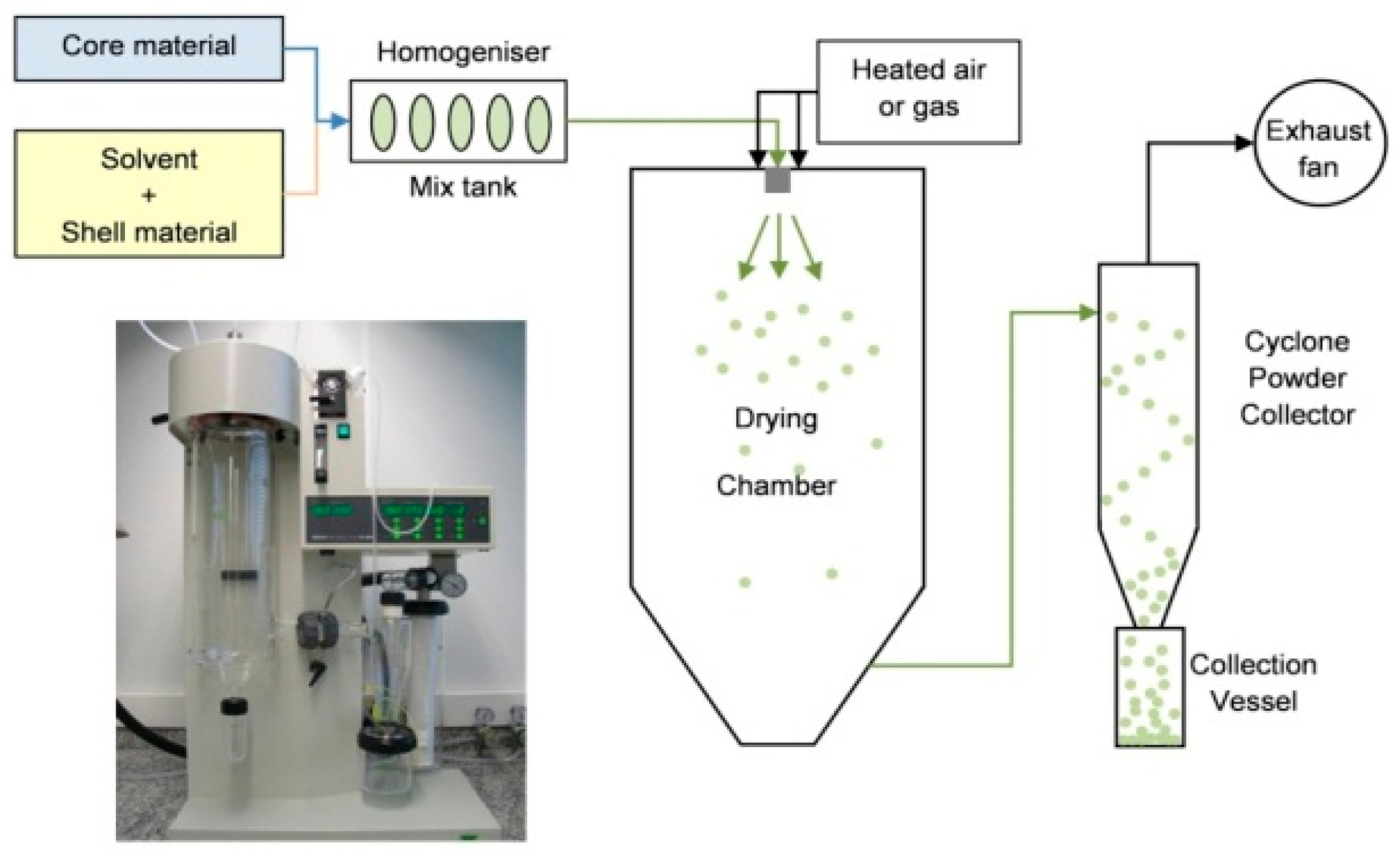
3.3.1. Spray Drying and Congealing
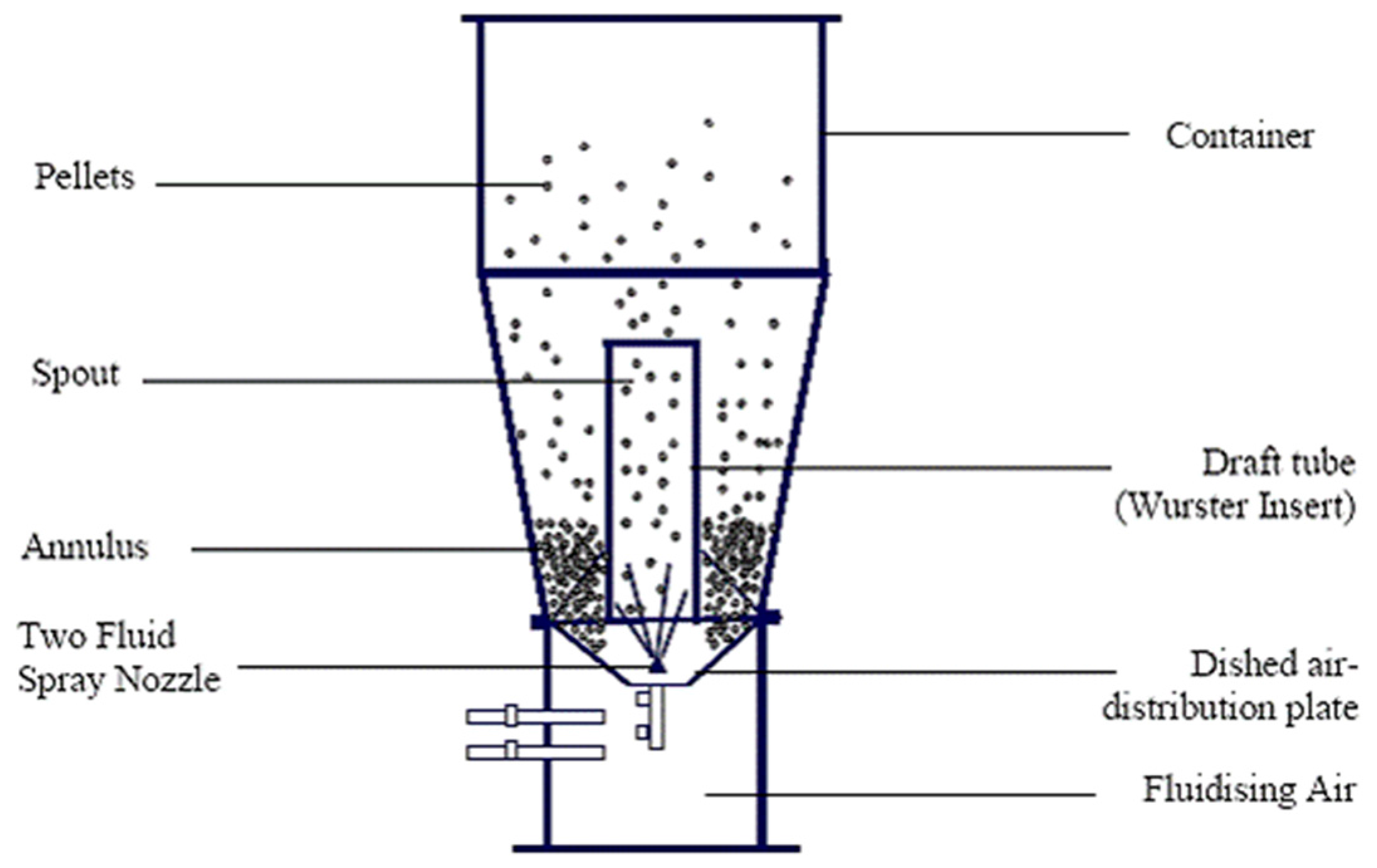
3.3.2. Fluid Bed Coating
3.3.3. Multi Orifice Centrifugal Process
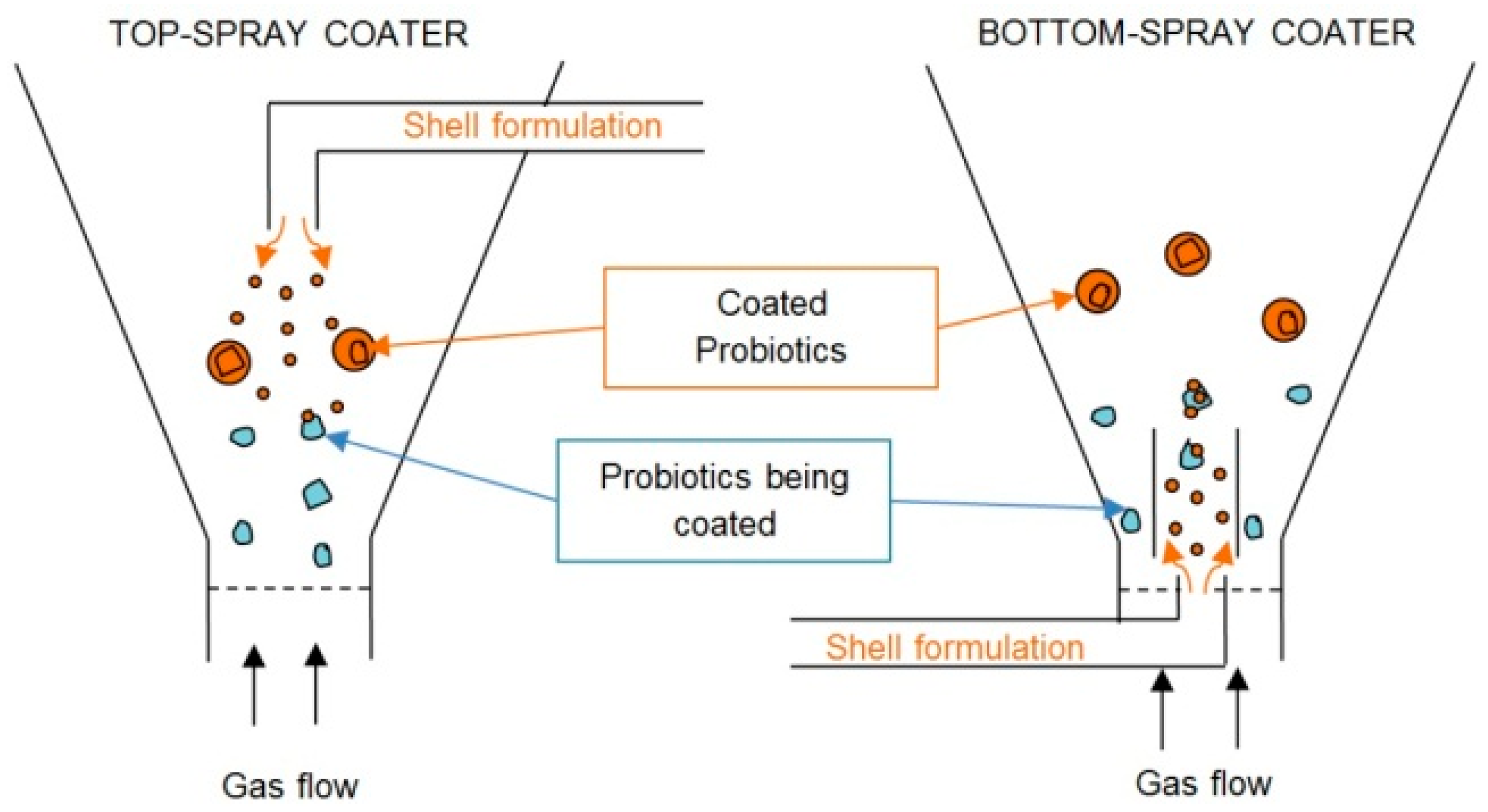
3.3.4. Air Suspension Coating
3.3.5. Pan Coating
4. Performance of Microencapsulated PCMs in Buildings
4.1. Modelling Studies
4.2. Experimental Studies
5. Problems of Microencapsulation
6. Conclusions and Recommendation
Acknowledgments
Author Contributions
Conflicts of Interest
Abbreviation
| Ø | Diameter |
| CNFs | Carbon Nano-fibers |
| DSC | Differential scanning calorimetry |
| EG | Expanded graphite |
| GNPs | Graphene Nano-platelets |
| HDPE | High-density polyethylene |
| ∆H | Latent heat |
| L-MWCNTs | Long multi-walled carbon Nano Tubes |
| LDPE | Low-density polyethylene |
| LLDPE | Linear low-density polyethylene |
| Tm | Melting temperature |
| µm | Micro meter |
| MePCMs | Microencapsulated phase change materials |
| NA | Information not available |
| NG | Nano graphite |
| PCM | Phase change material |
| PS | Polystyrene |
| Ra | Rayleigh number |
| S-MWCNTs | Short multi-walled carbon Nano-Tubes |
| Cp | Specific heat capacity |
| TABS | Thermally activated building system |
References
- Kuznik, F.; Virgone, J.; Noel, J. Optimization of a phase change material wallboard for building use. Appl. Therm. Eng. 2008, 28, 1291–1298. [Google Scholar] [CrossRef]
- Farid, M.M.; Khudhair, A.M.; Razack, S.A.K.; Al-Hallaj, S. A review on phase change energy storage: Materials and applications. Energy Convers. Manag. 2004, 45, 1597–1615. [Google Scholar] [CrossRef]
- Sharma, A.; Tyagi, V.V.; Chen, C.R.; Buddhi, D. Review on thermal energy storage with phase change materials and applications. Renew. Sustain. Energy Rev. 2009, 13, 318–345. [Google Scholar] [CrossRef]
- Kuznik, F.; David, D.; Johannes, K.; Roux, J.J. A review on phase change materials integrated in building walls. Renew. Sustain. Energy Rev. 2011, 15, 379–391. [Google Scholar] [CrossRef]
- Zalba, B.; Marı́n, J.M.; Cabeza, L.F.; Mehling, H. Review on thermal energy storage with phase change: Materials, heat transfer analysis and applications. Appl. Therm. Eng. 2003, 23, 251–283. [Google Scholar] [CrossRef]
- Zhou, D.; Zhao, C.Y.; Tian, Y. Review on thermal energy storage with phase change materials (PCMs) in building applications. Appl. Energy 2012, 92, 593–605. [Google Scholar] [CrossRef] [Green Version]
- Liu, L.; Su, D.; Tang, Y.; Fang, G. Thermal conductivity enhancement of phase change materials for thermal energy storage: A review. Renew. Sustain. Energy Rev. 2016, 62, 305–317. [Google Scholar] [CrossRef]
- Da Cunha, J.P.; Eames, P. Thermal energy storage for low and medium temperature applications using phase change materials—A review. Appl. Energy 2016, 177, 227–238. [Google Scholar] [CrossRef] [Green Version]
- Jurkowska, M.; Szczygieł, I. Review on properties of microencapsulated phase change materials slurries (mPCMS). Appl. Therm. Eng. 2016, 98, 365–373. [Google Scholar] [CrossRef]
- Akeiber, H.; Nejat, P.; Majid, M.Z.A.; Wahid, M.A.; Jomehzadeh, F.; Famileh, I.Z.; Zaki, S.A. A review on phase change material (PCM) for sustainable passive cooling in building envelopes. Renew. Sustain. Energy Rev. 2016, 60, 1470–1497. [Google Scholar] [CrossRef]
- Kylili, A.; Fokaides, P.A. Life Cycle Assessment (LCA) of Phase Change Materials (PCMs) for building applications: A review. J. Build. Eng. 2016, 6, 133–143. [Google Scholar] [CrossRef]
- Zhang, P.; Xiao, X.; Ma, Z.W. A review of the composite phase change materials: Fabrication, characterization, mathematical modeling and application to performance enhancement. Appl. Energy 2016, 165, 472–510. [Google Scholar] [CrossRef]
- Silva, T.; Vicente, R.; Rodrigues, F. Literature review on the use of phase change materials in glazing and shading solutions. Renew. Sustain. Energy Rev. 2016, 53, 515–535. [Google Scholar] [CrossRef]
- Bédécarrats, J.P.; Castaing-Lasvignottes, J.; Strub, F.; Dumas, J.P. Study of a phase change energy storage using spherical capsules. Part I: Experimental results. Energy Convers. Manag. 2009, 50, 2527–2536. [Google Scholar]
- Zhou, G.; Yang, Y.; Xu, H. Energy performance of a hybrid space-cooling system in an office building using SSPCM thermal storage and night ventilation. Sol. Energy 2011, 85, 477–485. [Google Scholar] [CrossRef]
- Mehling, H.; Schossig, P.; Kalz, D. Latent Heat Storage in Buildings; FIZ Karlsruhe GmbH: Eggenstein-Leopoldshafen, Germany, 2009. [Google Scholar]
- Yen, T.; Chen, H.J.; Huang, Y.L.; Ko, C.T. The dividing strength of lightweight aggregate concrete and the packing strength of light-weight aggregate. J. Chin. Inst. Eng. 1998, 21, 611–618. [Google Scholar] [CrossRef]
- Sarı, A.; Karaipekli, A.; Alkan, C. Preparation, characterization and thermal properties of lauric acid/expanded perlite as novel form-stable composite phase change material. Chem. Eng. J. 2009, 155, 899–904. [Google Scholar] [CrossRef]
- Khosrojerdi, M.; Mortazavi, S.M. Impregnation of a porous material with a PCM on a cotton fabric and the effect of vacuum on thermo-regulating textiles. J. Therm. Anal. Calorim. 2013, 114, 1111–1119. [Google Scholar] [CrossRef]
- Ingole, P.R.; Mohod, T.R.; Gaddamwar, S.S. Use of Phase Change Materials in Construction of Buildings: A Review. Int. J. Eng. Res. Gen. Sci. 2014, 2, 624–628. [Google Scholar]
- Cabeza, L.F.; Castellon, C.; Nogues, M.; Medrano, M.; Leppers, R.; Zubillaga, O. Use of microencapsulated PCM in concrete walls for energy savings. Energy Build. 2007, 39, 113–119. [Google Scholar] [CrossRef]
- Wang, X.; Zhang, Y.; Xiao, W.; Zeng, R.; Zhang, Q.; Di, H. Review on thermal performance of phase change energy storage building envelope. Chin. Sci. Bull. 2009, 54, 920–928. [Google Scholar] [CrossRef]
- Cabeza, L.F.; Roca, J.; Noguees, M.; Mehling, H.; Hiebler, S. Long term immersion corrosion tests on metal-PCM pairs used for latent heat storage in the 24 to 29° C temperature range. Mater. Corros. 2005, 56, 33–39. [Google Scholar] [CrossRef]
- Jacob, R.; Bruno, F. Review on shell materials used in the encapsulation of phase change materials for high temperature thermal energy storage. Renew. Sustain. Energy Rev. 2015, 48, 79–87. [Google Scholar] [CrossRef]
- Hawlader, M.N.A.; Uddin, M.S.; Khin, M.M. Microencapsulated PCM thermal-energy storage system. Appl. Energy 2003, 74, 195–202. [Google Scholar] [CrossRef]
- Dubey, R. Microencapsulation technology and applications. Def. Sci. J. 2009, 59, 82–95. [Google Scholar]
- Lam, P.L.; Gambari, R.; Kok, S.L.; Lam, K.H.; Tang, J.O.; Bian, Z.X.; Chui, C.H. Non-toxic agarose/gelatin-based microencapsulation system containing gallic acid for antifungal application. Int. J. Mol. Med. 2015, 35, 503–510. [Google Scholar] [CrossRef] [PubMed]
- Salazar-López, E.I.; Jiménez, M.; Salazar, R.; Azuara, E. Incorporation of microcapsules in pineapple intercellular tissue using osmotic dehydration and microencapsulation method. Food Bioprocess Technol. 2015, 8, 1699–1706. [Google Scholar] [CrossRef]
- Sarı, A.; Alkan, C.; Döğüşcü, D.K.; Kızıl, Ç. Micro/nano encapsulated N-tetracosane and N-octadecane eutectic mixture with polystyrene shell for low-temperature latent heat thermal energy storage applications. Sol. Energy 2015, 115, 195–203. [Google Scholar] [CrossRef]
- Butstraen, C.; Salaün, F.; Devaux, E. Sol–gel microencapsulation of oil phase with Pickering and nonionic surfactant based emulsions. Powder Technol. 2015, 284, 237–244. [Google Scholar] [CrossRef]
- Carvalho, I.T.; Estevinho, B.N.; Santos, L. Application of microencapsulated essential oils in cosmetic and personal healthcare products—A review. Int. J. Cosmet. Sci. 2016, 38, 109–119. [Google Scholar] [CrossRef] [PubMed]
- Mahdavi, S.A.; Jafari, S.M.; Assadpoor, E.; Dehnad, D. Microencapsulation optimization of natural anthocyanins with maltodextrin, gum Arabic and gelatin. Int. J. Biol. Macromol. 2016, 85, 379–385. [Google Scholar] [CrossRef] [PubMed]
- Sarı, A.; Alkan, C.; Karaipekli, A.; Uzun, O. Microencapsulated N-octacosane as phase change material for thermal energy storage. Sol. Energy 2009, 83, 1757–1763. [Google Scholar] [CrossRef]
- Pan, L.; Tao, Q.; Zhang, S.; Wang, S.; Zhang, J.; Wang, S.; Zhang, Z. Preparation, characterization and thermal properties of micro-encapsulated phase change materials. Sol. Energy Mater. Sol. Cells 2012, 98, 66–70. [Google Scholar] [CrossRef]
- Cellat, K.; Beyhan, B.; Güngör, C.; Konuklu, Y.; Karahan, O.; Dündar, C.; Paksoy, H. Thermal enhancement of concrete by adding bio-based fatty acids as phase change materials. Energy Build. 2015, 106, 156–163. [Google Scholar] [CrossRef]
- Ge, H.; Li, H.; Mei, S.; Liu, J. Low melting point liquid metal as a new class of phase change material: An emerging frontier in energy area. Renew. Sustain. Energy Rev. 2013, 21, 331–346. [Google Scholar] [CrossRef]
- Konuklu, Y.; Ostry, M.; Paksoy, H.O.; Charvat, P. Review on using microencapsulated phase change materials (PCM) in building applications. Energy Build. 2015, 106, 134–155. [Google Scholar] [CrossRef]
- Nkwetta, D.N.; Haghighat, F. Thermal energy storage with phase change material—A state-of-the art review. Sustain. Cities Soc. 2014, 10, 87–100. [Google Scholar] [CrossRef]
- The Candle Making Shop. Available online: http://www.thecandlemakingshop.co.uk/Candle-Wax/Bulk-Waxes/pure-paraffin-wax-20kg.aspx (accessed on 21 December 2015).
- Anghel, E.M.; Georgiev, A.; Petrescu, S.; Popov, R.; Constantinescu, M. Thermo-physical characterization of some paraffins used as phase change materials for thermal energy storage. J. Therm. Anal. Calorim. 2014, 117, 557–566. [Google Scholar] [CrossRef]
- Kośny, J. Short History of PCM Applications in Building Envelopes. In PCM-Enhanced Building Components; Springer International Publishing: Basel, Switzerland, 2015; pp. 21–59. [Google Scholar]
- The Engineering ToolBox. Available online: http://www.engineeringtoolbox.com/thermal-conductivity-d_429.html (accessed on 25 February 2016).
- Hough, T.P. Solar Energy: New Research; Nova Publishers: New York, NY, USA, 2006. [Google Scholar]
- Mehrali, M.; Latibari, S.T.; Mehrali, M.; Metselaar, H.S.C.; Silakhori, M. Shape-stabilized phase change materials with high thermal conductivity based on paraffin/graphene oxide composite. Energy Convers. Manag. 2013, 67, 275–282. [Google Scholar] [CrossRef]
- Chung, D.D.L. Thermal interface materials. J. Mater. Eng. Perform. 2001, 10, 56–59. [Google Scholar] [CrossRef]
- Karaıpeklı, A.; Sarı, A.; Kaygusuz, K. Thermal characteristics of paraffin/expanded perlite composite for latent heat thermal energy storage. Energy Sources A 2009, 31, 814–823. [Google Scholar] [CrossRef]
- Garg, H.P.; Mullick, S.C.; Bhargava, A.K. Latent Heat or Phase Change Thermal Energy Storage. In Solar Thermal Energy Storage; Springer: Berlin, Germany, 1985; pp. 154–291. [Google Scholar]
- Hasan, A.; McCormack, S.J.; Huang, M.J.; Norton, B. Evaluation of phase change materials for thermal regulation enhancement of building integrated photovoltaics. Sol. Energy 2010, 84, 1601–1612. [Google Scholar] [CrossRef]
- Stekli, J.; Irwin, L.; Pitchumani, R. Technical challenges and opportunities for concentrating solar power with thermal energy storage. J. Therm. Sci. Eng. Appl. 2013, 5, 021011. [Google Scholar] [CrossRef]
- Ungar, G.; Keller, A. Long range intermixing of paraffin molecules in the crystalline state. Colloid Polym. Sci. 1979, 257, 90–94. [Google Scholar] [CrossRef]
- Navarro, L.; de Gracia, A.; Castell, A.; Cabeza, L.F. Thermal behaviour of insulation and phase change materials in buildings with internal heat loads: Experimental study. Energy Effic. 2015, 8, 895–904. [Google Scholar] [CrossRef]
- Li, M. A nano-graphite/paraffin phase change material with high thermal conductivity. Appl. Energy 2013, 106, 25–30. [Google Scholar] [CrossRef]
- Ettouney, H.; El-Dessouky, H.; Al-Ali, A. Heat transfer during phase change of paraffin wax stored in spherical shells. J. Sol. Energy Eng. 2005, 127, 357–365. [Google Scholar] [CrossRef]
- Zhang, X.; Tian, J.; Wang, L.; Zhou, Z. Wettability effect of coatings on drag reduction and paraffin deposition prevention in oil. J. Pet. Sci. Eng. 2002, 36, 87–95. [Google Scholar] [CrossRef]
- Sigma-Aldrich, a Part of Merck. Available online: https://www.sigmaaldrich.com/canada-english.html (accessed on 20 August 2016).
- Albury, A. Flash Point: A Comparison of PureTemp and Paraffin PCMs; Entropy Solutions International: Plymouth, MN, USA, 2014. [Google Scholar]
- Rao, Z.H.; Wang, S.H.; Zhang, Y.L.; Zhang, G.Q.; Zhang, J.Y. Thermal Properties of Paraffin/Nano-AlN Phase Change Energy Storage Materials. Energy Sources A Recov. Util. Environ. Eff. 2014, 36, 2281–2286. [Google Scholar] [CrossRef]
- Yu, S.; Wang, X.; Wu, D. Microencapsulation of N-octadecane phase change material with calcium carbonate shell for enhancement of thermal conductivity and serving durability: Synthesis, microstructure, and performance evaluation. Appl. Energy 2014, 114, 632–643. [Google Scholar] [CrossRef]
- Jin, Z.; Wang, Y.; Liu, J.; Yang, Z. Synthesis and properties of paraffin capsules as phase change materials. Polymer 2008, 49, 2903–2910. [Google Scholar] [CrossRef]
- Yin, D.; Ma, L.; Liu, J.; Zhang, Q. Pickering emulsion: A novel template for microencapsulated phase change materials with polymer–silica hybrid shell. Energy 2014, 64, 575–581. [Google Scholar] [CrossRef]
- Yang, Y.; Ye, X.; Luo, J.; Song, G.; Liu, Y.; Tang, G. Polymethyl methacrylate based phase change microencapsulation for solar energy storage with silicon nitride. Sol. Energy 2015, 115, 289–296. [Google Scholar] [CrossRef]
- Kośny, J. Analysis of the Dynamic Thermal Performance of Fiberous Insulations Containing Phase Change Materials; Oak Ridge National Laboratory: Oak Ridge, TN, USA, 2009. [Google Scholar]
- Cui, Y.; Liu, C.; Hu, S.; Yu, X. The experimental exploration of carbon nanofiber and carbon nanotube additives on thermal behavior of phase change materials. Sol. Energy Mater. Sol. Cells 2011, 95, 1208–1212. [Google Scholar] [CrossRef]
- Serrano, S.; Barreneche, C.; Rincón, L.; Boer, D.; Cabeza, L.F. Optimization of three new compositions of stabilized rammed earth incorporating PCM: Thermal properties characterization and LCA. Constr. Build. Mater. 2013, 47, 872–878. [Google Scholar] [CrossRef]
- Lai, C.M.; Hokoi, S. Thermal performance of an aluminum honeycomb wallboard incorporating microencapsulated PCM. Energy Build. 2014, 73, 37–47. [Google Scholar] [CrossRef]
- Kheradmand, M.; Azenha, M.; de Aguiar, J.L.; Krakowiak, K.J. Thermal behavior of cement based plastering mortar containing hybrid microencapsulated phase change materials. Energy Build. 2014, 84, 526–536. [Google Scholar] [CrossRef]
- Jeong, S.G.; Jeon, J.; Seo, J.; Lee, J.H.; Kim, S. Performance evaluation of the microencapsulated PCM for wood-based flooring application. Energy Convers. Manag. 2012, 64, 516–521. [Google Scholar] [CrossRef]
- Li, Z.; Sun, W.G.; Wang, G.; Wu, Z.G. Experimental and numerical study on the effective thermal conductivity of paraffin/expanded graphite composite. Sol. Energy Mater. Sol. Cells 2014, 128, 447–455. [Google Scholar] [CrossRef]
- Fan, L.W.; Fang, X.; Wang, X.; Zeng, Y.; Xiao, Y.Q.; Yu, Z.T.; Cen, K.F. Effects of various carbon nanofillers on the thermal conductivity and energy storage properties of paraffin-based nanocomposite phase change materials. Appl. Energy 2013, 110, 163–172. [Google Scholar] [CrossRef]
- Chen, F.; Wolcott, M. Polyethylene/paraffin binary composites for phase change material energy storage in building: A morphology, thermal properties, and paraffin leakage study. Sol. Energy Mater. Sol. Cells 2015, 137, 79–85. [Google Scholar] [CrossRef]
- Zhang, H.; Wang, X.; Wu, D. Silica encapsulation of N-octadecane via sol–gel process: A novel microencapsulated phase-change material with enhanced thermal conductivity and performance. J. Colloid Interface Sci. 2010, 343, 246–255. [Google Scholar] [CrossRef] [PubMed]
- He, F.; Wang, X.; Wu, D. New approach for sol–gel synthesis of microencapsulated N-octadecane phase change material with silica wall using sodium silicate precursor. Energy 2014, 67, 223–233. [Google Scholar] [CrossRef]
- Özonur, Y.; Mazman, M.; Paksoy, H.Ö.; Evliya, H. Microencapsulation of coco fatty acid mixture for thermal energy storage with phase change material. Int. J. Energy Res. 2006, 30, 741–749. [Google Scholar] [CrossRef]
- He, H.; Zhao, P.; Yue, Q.; Gao, B.; Yue, D.; Li, Q. A novel polynary fatty acid/sludge ceramsite composite phase change materials and its applications in building energy conservation. Renew. Energy 2015, 76, 45–52. [Google Scholar] [CrossRef]
- Sharma, A.; Shukla, A.; Chen, C.R.; Dwivedi, S. Development of phase change materials for building applications. Energy Build. 2013, 64, 403–407. [Google Scholar] [CrossRef]
- Tang, F.; Cao, L.; Fang, G. Preparation and thermal properties of stearic acid/titanium dioxide composites as shape-stabilized phase change materials for building thermal energy storage. Energy Build. 2014, 80, 352–357. [Google Scholar] [CrossRef]
- Chen, Z.; Cao, L.; Shan, F.; Fang, G. Preparation and characteristics of microencapsulated stearic acid as composite thermal energy storage material in buildings. Energy Build. 2013, 62, 469–474. [Google Scholar] [CrossRef]
- Konuklu, Y.; Unal, M.; Paksoy, H.O. Microencapsulation of caprylic acid with different wall materials as phase change material for thermal energy storage. Sol. Energy Mater. Sol. Cells 2014, 120, 536–542. [Google Scholar] [CrossRef]
- Garg, H.P.; Mullick, S.C.; Bhargava, V.K. Solar Thermal Energy Storage; Springer Science & Business Media: Berlin, Germany, 2012. [Google Scholar]
- U.S. Environmental Protection Agency (EPA). 2016. Available online: http://actor.epa.gov/actor/faces/Assay.jsp (accessed on 5 January 2016).
- Government of Dubai. Green Building Regulations & Specifications; Government of Dubai: Dubai, UAE, 2011.
- Sarı, A.; Kaygusuz, K. Some fatty acids used for latent heat storage: Thermal stability and corrosion of metals with respect to thermal cycling. Renew. Energy 2003, 28, 939–948. [Google Scholar] [CrossRef]
- Lin, W.; Ma, Z.; Sohel, M.I.; Cooper, P. Development and evaluation of a ceiling ventilation system enhanced by solar photovoltaic thermal collectors and phase change materials. Energy Convers. Manag. 2014, 88, 218–230. [Google Scholar] [CrossRef]
- PAN Pesticides Database—Chemicals. Available online: http://www.pesticideinfo.org/Detail_Chemical.jsp?Rec_Id=PC33152#Toxicity (accessed on 5 January 2016).
- Ku, W.H.; Lau, D.C.Y.; Huen, K.F. Probiotics Provoked d-lactic Acidosis in Short Bowel Syndrome: Case Report and Literature Review. HK J. Paediatr. 2006, 11, 246–254. [Google Scholar]
- Patil, G. Review of phase change materials useful for thermal storage system. Glob. J. Adv. Eng. Technol. Sci. 2015, 11, 1–5. [Google Scholar]
- Townsend Letter. 2015. Available online: http://www.townsendletter.com/Jan2015/green0115.html (accessed on 5 January 2016).
- NingxiaJiafeng Chemicals Co., Ltd. Available online: http://jiafengchem.com.cn/en/product_detail.aspx?ProductsCateID=60&ProductsID=21&gclid=CPKgtf69ksoCFSfkwgoda0YLug (accessed on 5 January 2016).
- CAMEO Chemicals. Available online: http://cameochemicals.noaa.gov/chemical/22150 (accessed on 5 January 2016).
- Bhatt, V.D.; Gohil, K.; Mishra, A. Thermal energy storage capacity of some phase changing materials and ionic liquids. Int. J. ChemTech Res. 2010, 2, 1771e9. [Google Scholar]
- Norton, B. Harnessing Solar Heat; Springer: Berlin, Germany, 2014. [Google Scholar]
- Veerappan, M.; Kalaiselvam, S.; Iniyan, S.; Goic, R. Phase change characteristic study of spherical PCMs in solar energy storage. Sol. Energy 2009, 83, 1245–1252. [Google Scholar] [CrossRef]
- PCM Price Challenge. Available online: https://cdn2.hubspot.net/hub/55819/file-30934935-pdf/docs/pcm_price_challenge.pdf (accessed on 20 June 2016).
- Gawron, K.; Schröder, J. Properties of some salt hydrates for latent heat storage. Int. J. Energy Res. 1977, 1, 351–363. [Google Scholar] [CrossRef]
- Berroug, F.; Lakhal, E.K.; El Omari, M.; Faraji, M.; El Qarnia, H. Thermal performance of a greenhouse with a phase change material north wall. Energy Build. 2011, 43, 3027–3035. [Google Scholar] [CrossRef]
- Zhou, D.; Zhao, C.Y. Experimental investigations on heat transfer in phase change materials (PCMs) embedded in porous materials. Appl. Therm. Eng. 2011, 31, 970–977. [Google Scholar] [CrossRef]
- N’Tsoukpoe, K.; Rammelberg, H.U.; Lele, A.F.; Korhammer, K.; Watts, B.A.; Schmidt, T.; Wolfgang, K.L. A review on the use of calcium chloride in applied thermal engineering. Appl. Therm. Eng. 2015, 75, 513–531. [Google Scholar] [CrossRef]
- Sharma, S.D.; Kitano, H.; Sagara, K. Phase change materials for low temperature solar thermal applications. Res. Rep. Fac. Eng. 2004, 29, 31–64. [Google Scholar]
- Gruszkiewicz, M.S.; Simonson, J.M. Vapor pressures and isopiestic molalities of concentrated CaCl2(aq), CaBr2(aq), and NaCl(aq). J. Chem. Thermodyn. 2005, 37, 906–930. [Google Scholar] [CrossRef]
- Kenisarin, M.; Mahkamov, K. Salt hydrates as latent heat storage materials: Thermophysical properties and costs. Sol. Energy. Mater. Sol. Cells 2016, 145, 255–286. [Google Scholar] [CrossRef]
- Tyagi, V.V.; Buddhi, D. Thermal cycle testing of calcium chloride hexahydrate as a possible PCM for latent heat storage. Sol. Energy. Mater. Sol. Cells 2008, 92, 891–899. [Google Scholar] [CrossRef]
- Kaygusuz, K. Experimental and theoretical investigation of latent heat storage for water based solar heating systems. Energy Convers. Manag. 1995, 36, 315–323. [Google Scholar] [CrossRef]
- Cabeza, L.F.; Illa, J.; Roca, J.; Badia, F.; Mehling, H.; Hiebler, S. Middle term immersion corrosion tests on metal-salt hydrate pairs used for latent heat storage in the 32 to 36 °C temperature range. Mater. Corros. 2001, 52, 748–754. [Google Scholar] [CrossRef]
- Lane, G.A. Macro-Encapsulation of PCM; Report No. ORO/5117-8; Dow Chemical Company: Midland, MI, USA, 1978. [Google Scholar]
- Biswas, R. Thermal storage using sodium sulfate decahydrate and water. Sol. Energy 1977, 99, 99–100. [Google Scholar] [CrossRef]
- Charlsson, B.; Stymme, H.; Wattermark, G. An incongruent heat of fusion system CaCl26H2O made congruent through modification of chemical composition of the system. Sol. Energy 1979, 23, 343–350. [Google Scholar]
- Alexiades, V.; Solomon Alan, D. Mathematical Modeling of Melting and Freezing Process; Hemisphere Publishing Corporation: Washington, DC, USA, 1992. [Google Scholar]
- Lane, G.A.; Rossow, H.E. Encapsulation of heat of fusion storage materials. In Proceedings of the Second South Eastern Conference on Application of Solar Energy, Baton Rouge, LA, USA, 19–22 April 1976; pp. 442–455.
- Telkes, M. Thermal storage for solar heating and cooling. In Proceedings of the Workshop on Solar Energy Storage Sub-Systems for Heating and Cooling of Buildings, Charlottesville, VA, USA, 16–18 April 1975.
- Telkes, M. Nucleation of super saturated inorganic salt solution. Ind. Eng. Chem. 1952, 44, 1308–1310. [Google Scholar] [CrossRef]
- Leoni, N.; Amon, C.H. Transient thermal design of wearable computers with embedded electronics using phase change materials. In Proceedings of the 32nd ASME National Heat Transfer Conference, Baltimore, MD, USA, 8–12 August 1997; pp. 49–56.
- Hadjieva, M.; Stoykov, R.; Filipova, T.Z. Composite salt-hydrate concrete system for building energy storage. Renew. Energy 2000, 19, 111–115. [Google Scholar] [CrossRef]
- Lee, K.O.; Medina, M.A.; Raith, E.; Sun, X. Assessing the integration of a thin phase change material (PCM) layer in a residential building wall for heat transfer reduction and management. Appl. Energy 2015, 137, 699–706. [Google Scholar] [CrossRef]
- Zhong, L.; Zhang, X.; Luan, Y.; Wang, G.; Feng, Y.; Feng, D. Preparation and thermal properties of porous heterogeneous composite phase change materials based on molten salts/expanded graphite. Sol. Energy 2014, 107, 63–73. [Google Scholar] [CrossRef]
- Huang, J.; Wang, T.; Zhu, P.; Xiao, J. Preparation, characterization, and thermal properties of the microencapsulation of a hydrated salt as phase change energy storage materials. Thermochim. Acta 2013, 557, 1–6. [Google Scholar] [CrossRef]
- Su, W.; Darkwa, J.; Kokogiannakis, G. Review of solid–liquid phase change materials and their encapsulation technologies. Renew. Sustain. Energy Rev. 2015, 48, 373–391. [Google Scholar] [CrossRef]
- Kumar, R.; Misra, M.K.; Kumar, R.; Gupta, D.; Khatri, P.K.; Tak, B.B.; Meena, S.R. Phase Change Materials: Technology Status and Potential Defence Applications (Review Papers). Def. Sci. J. 2011, 61, 576–582. [Google Scholar] [CrossRef]
- Ma, K.; Liu, J. Liquid metal cooling in thermal management of computer chips. Front. Energy Power Eng. China 2007, 1, 384–402. [Google Scholar] [CrossRef]
- Deng, Y.; Liu, J. A liquid metal cooling system for the thermal management of high power LEDs. Int. Commun. Heat Mass Transf. 2010, 37, 788–791. [Google Scholar] [CrossRef]
- Li, H.; Liu, J. Revolutionizing heat transport enhancement with liquid metals: Proposal of a new industry of water-free heat exchangers. Front. Energy 2011, 5, 20–42. [Google Scholar] [CrossRef]
- Li, P.; Liu, J. Harvesting low grade heat to generate electricity with thermosyphon effect of room temperature liquid metal. Appl. Phys. Lett. 2011, 99, 094106. [Google Scholar] [CrossRef]
- Dai, D.; Zhou, Y.; Liu, J. Liquid metal based thermoelectric generation system for waste heat recovery. Renew. Energy 2011, 36, 3530–3536. [Google Scholar] [CrossRef]
- Zhang, Q.; Liu, J. Nano liquid metal as an emerging functional material in energy management, conversion and storage. Nano Energy 2013, 2, 863–872. [Google Scholar] [CrossRef]
- BASF SE. Available online: http://www.micronal.de/portal/load/fid774774/Catalogue%20Micronal%20PCM.pdf (accessed on 9 March 2016).
- Rubitherm Technologies GmbH. Available online: http://www.rubitherm.eu/produktkategorien.html (accessed on 9 March 2016).
- Microtek Laboratories, Inc. Available online: http://www.microteklabs.com/data-sheets.html (accessed on 9 March 2016).
- SavEnrg™ Phase Change Material. Available online: http://rgees.com/products.php (accessed on 9 March 2016).
- Phase Change Products Pty Ltd. (PCP). Available online: http://pcpaustralia.com.au/ (accessed on 9 March 2016).
- PCM Energy P. Ltd. Available online: http://pcmenergy.com/products.htm (accessed on 9 March 2016).
- Phase Change Material Products Limited. Available online: http://www.pcmproducts.net/Phase_Change_Material_Products.htm (accessed on 9 March 2016).
- Climator Sweden AB. Available online: http://climator.com/room-en/?lang=en (accessed on 9 March 2016).
- Salca BV. Available online: http://www.salcabv.nl/index.asp?CategorieID=2&Taal=EN (accessed on 9 March 2016).
- Entropy Solutions, LLC. Available online: http://www.puretemp.com/stories/puretemp-technical-data-sheets (accessed on 9 March 2016).
- Karthikeyan, M.; Ramachandran, T. Review of thermal energy storage of micro-and nanoencapsulated phase change materials. Mater. Res. Innov. 2014, 18, 541–554. [Google Scholar] [CrossRef]
- Ukrainczyk, N.; Kurajica, S.; Šipušić, J. Thermophysical comparison of five commercial paraffin waxes as latent heat storage materials. Chem. Biochem. Eng. Q. 2010, 24, 129–137. [Google Scholar]
- Kalinov, B.P.; Pereverzev, A.N.; Pivovarov, A.T.; Shtapova, V.K. Interconnection of the parameters of the quality of a paraffin distillate from ozerksuatsk petroleum. Chem. Technol. Fuels Oils 1968, 4, 331–334. [Google Scholar] [CrossRef]
- Yuan, Y.; Lee, T.R. Contact angle and wetting properties. In Surface Science Techniques; Springer: Berlin/Heidelberg, Germany, 2013; pp. 3–34. [Google Scholar]
- Sohns, J.; Seifert, B.; Hahne, E. The effect of impurities on the melting temperature and the heat of fusion of latent heat storage materials. Int. J. Thermophys. 1981, 2, 71–87. [Google Scholar] [CrossRef]
- Cabeza, L.F.; Mehling, H. Solid-Liquid Phase Change Materials. In Heat and Cold Storage with PCM—An Up to Date Introduction into Basics and Applications; Springer: Berlin, Germany, 2008; p. 308. [Google Scholar]
- Sandnes, B.; Rekstad, J. Supercooling salt hydrates: Stored enthalpy as a function of temperature. Sol. Energy 2006, 80, 616–625. [Google Scholar] [CrossRef]
- Galwey, A.K.; Brown, M.E. Thermal Decomposition of Ionic Solids: Chemical Properties and Reactivities of Ionic Crystalline Phases; Elsevier: Amsterdam, The Netherlands, 1999; Volume 86. [Google Scholar]
- Kenisarin, M.; Mahkamov, K. Solar energy storage using phase change materials. Renew. Sustain. Energy Rev. 2007, 11, 1913–1965. [Google Scholar] [CrossRef]
- Umer, H.; Nigam, H.; Tamboli, A.M.; Nainar, M.S.M. Microencapsulation: Process, techniques and applications. Int. J. Res. Pharm. Biomed. Sci. 2011, 2, 474–480. [Google Scholar]
- Xing, J.; Li, Y.; Newton, E.; Yeung, K.-W. Method for Encapsulating Paraffin Compounds that Can Undergo Phase Transitional and Microcapsule Resulting Therefrom. Patent WO 2003099427 A1, 4 December 2003. [Google Scholar]
- Liang, C.; Lingling, X.; Hongbo, S.; Zhibin, Z. Microencapsulation of butyl stearate as a phase change material by interfacial polycondensation in a polyurea system. Energy Convers. Manag. 2009, 50, 723–729. [Google Scholar] [CrossRef]
- Cho, J.S.; Kwon, A.; Cho, C.G. Microencapsulation of octadecane as a phase-change material by interfacial polymerization in an emulsion system. Colloid Polym. Sci. 2002, 280, 260–266. [Google Scholar] [CrossRef]
- Saihi, D.; Vroman, I.; Giraud, S.; Bourbigot, S. Microencapsulation of ammonium phosphate with a polyurethane shell. Part II. Interfacial polymerization technique. React. Funct. Polym. 2006, 66, 1118–1125. [Google Scholar] [CrossRef]
- Salaün, F.; Bedek, G.; Devaux, E.; Dupont, D.; Gengembre, L. Microencapsulation of a cooling agent by interfacial polymerization: Influence of the parameters of encapsulation on poly (urethane–urea) microparticles characteristics. J. Membr. Sci. 2011, 370, 23–33. [Google Scholar] [CrossRef]
- Lu, S.; Xing, J.; Zhang, Z.; Jia, G. Preparation and characterization of polyurea/polyurethane double-shell microcapsules containing butyl stearate through interfacial polymerization. J. Appl. Polym. Sci. 2011, 121, 3377–3383. [Google Scholar] [CrossRef]
- Su, J.F.; Wang, L.X.; Ren, L.; Huang, Z.; Meng, X.W. Preparation and characterization of polyurethane microcapsules containing n-octadecane with styrene-maleic anhydride as a surfactant by interfacial polycondensation. J. Appl. Polym. Sci. 2006, 102, 4996–5006. [Google Scholar] [CrossRef]
- Siddhan, P.; Jassal, M.; Agrawal, A.K. Core content and stability of n-octadecane-containing polyurea microencapsules produced by interfacial polymerization. J. Appl. Polym. Sci. 2007, 106, 786–792. [Google Scholar] [CrossRef]
- Microencapsulation. Available online: https://uqu.edu.sa/files2/tiny_mce/plugins/filemanager/files/4290121/MICROENCAPSULATION.pdf (accessed on 29 February 2016).
- Swapan, K.G. Functional Coatings by Polymer Microencapsulation; Wiley-VCH: Weinheim, Germany, 2006. [Google Scholar]
- You, M.; Zhang, X.X.; Li, W.; Wang, X.C. Effects of MicroPCMs on the fabrication of MicroPCMs/polyurethane composite foams. Thermochim. Acta 2008, 472, 20–24. [Google Scholar] [CrossRef]
- Sarier, N.; Onder, E. The manufacture of microencapsulated phase change materials suitable for the design of thermally enhanced fabrics. Thermochim Acta 2007, 452, 149–160. [Google Scholar] [CrossRef]
- Lee, S.H.; Yoon, S.J.; Kim, Y.G.; Choi, Y.C.; Kim, J.H.; Lee, J.G. Development of building materials by using micro-encapsulated phase change material. Korean J. Chem. Eng. 2007, 24, 332–335. [Google Scholar] [CrossRef]
- Boh, B.; Knez, E.; Staresinic, M. Microencapsulation of higher hydrocarbon phase change materials by in situ polymerization. J. Microencapsul. 2005, 22, 715–735. [Google Scholar] [CrossRef] [PubMed]
- Fang, G.; Li, H.; Yang, F.; Liu, X.; Wu, S. Preparation and characterization of nano-encapsulated N-tetradecane as phase change material for thermal energy storage. Chem. Eng. J. 2009, 153, 217–221. [Google Scholar] [CrossRef]
- Hu, X.; Huang, Z.; Yu, X.; Li, B. Preparation and thermal energy storage of carboxymethyl cellulose-modified nanocapsules. BioEnergy Res. 2013, 6, 1135–1141. [Google Scholar] [CrossRef]
- Karthikeyan, M.; Ramachandran, T.; Sundaram, O.S. Nanoencapsulated phase change materials based on polyethylene glycol for creating thermoregulating cotton. J. Ind. Text. 2014, 44, 130–146. [Google Scholar] [CrossRef]
- Fei, X.; Zhao, H.; Zhang, B.; Cao, L.; Yu, M.; Zhou, J.; Yu, L. Microencapsulation mechanism and size control of fragrance microcapsules with melamine resin shell. Colloids Surf. A Physicochem. Eng. Asp. 2015, 469, 300–306. [Google Scholar] [CrossRef]
- Benita, S. Microencapsulation: Methods and Industrial Applications; CRC Press: Boca Raton, FL, USA, 2005. [Google Scholar]
- Saihi, D.; Vroman, I.; Giraud, S.; Bourbigot, S. Microencapsulation of ammonium phosphate with a polyurethane shell part I: Coacervation technique. React. Funct. Polym. 2005, 64, 127–138. [Google Scholar] [CrossRef]
- Jamekhorshid, A.; Sadrameli, S.M.; Farid, M. A review of microencapsulation methods of phase change materials (PCMs) as a thermal energy storage (TES) medium. Renew. Sustain. Energy Rev. 2014, 31, 531–542. [Google Scholar] [CrossRef]
- Mishra, M. Handbook of Encapsulation and Controlled Release; CRC Press: Boca Raton, FL, USA, 2015. [Google Scholar]
- Piacentini, E.; Giorno, L.; Dragosavac, M.M.; Vladisavljević, G.T.; Holdich, R.G. Microencapsulation of oil droplets using cold water fish gelatine/gum arabic complex coacervation by membrane emulsification. Food Res. Int. 2013, 53, 362–372. [Google Scholar] [CrossRef] [Green Version]
- Onder, E.; Sarier, N.; Cimen, E. Encapsulation of phase change materials by complex coacervation to improve thermal performances of woven fabrics. Thermochim. Acta 2008, 467, 63–72. [Google Scholar] [CrossRef]
- Mayya, K.S.; Bhattacharyya, A.; Argillier, J.F. Micro-encapsulation by complex coacervation: Influence of surfactant. Polym. Int. 2003, 52, 644–647. [Google Scholar] [CrossRef]
- Su, J.F.; Huang, Z.; Ren, L. High compact melamine-formaldehyde microPCMs containing N-octadecane fabricated by a two-step coacervation method. Colloid Polym. Sci. 2007, 285, 1581–1591. [Google Scholar] [CrossRef]
- Cao, L.; Tang, F.; Fang, G. Synthesis and characterization of microencapsulated paraffin with titanium dioxide shell as shape-stabilized thermal energy storage materials in buildings. Energy Build. 2014, 72, 31–37. [Google Scholar] [CrossRef]
- Pan, W.; Ye, J.; Ning, G.; Lin, Y.; Wang, J. A novel synthesis of micrometer silica hollow sphere. Mater. Res. Bull. 2009, 44, 280–283. [Google Scholar] [CrossRef]
- Zhang, H.; Wu, J.; Zhou, L.; Zhang, D.; Qi, L. Facile synthesis of monodisperse microspheres and gigantic hollow shells of mesoporous silica in mixed water-ethanol solvents. Langmuir 2007, 23, 1107–1113. [Google Scholar] [CrossRef] [PubMed]
- Deng, Z.; Chen, M.; Zhou, S.; You, B.; Wu, L. A novel method for the fabrication of monodisperse hollow silica spheres. Langmuir 2006, 22, 6403–6407. [Google Scholar] [CrossRef] [PubMed]
- Cape, S.P.; Villa, J.A.; Huang, E.T.; Yang, T.H.; Carpenter, J.F.; Sievers, R.E. Preparation of active proteins, vaccines and pharmaceuticals as fine powders using supercritical or near-critical fluids. Pharm. Res. 2008, 25, 1967–1990. [Google Scholar] [CrossRef] [PubMed]
- Campardelli, R.; Oleandro, E.; Reverchon, E. Supercritical assisted injection in a liquid antisolvent for PLGA and PLA microparticle production. Powder Technol. 2016, 287, 12–19. [Google Scholar] [CrossRef]
- Campardelli, R.; Santo, I.E.; Albuquerque, E.C.; de Melo, S.V.; Della Porta, G.; Reverchon, E. Efficient encapsulation of proteins in submicro liposomes using a supercritical fluid assisted continuous process. J. Supercrit. Fluids 2016, 107, 163–169. [Google Scholar] [CrossRef]
- Ivanovic, J.; Milovanovic, S.; Zizovic, I. Utilization of supercritical CO2 as a processing aid in setting functionality of starch-based materials. Starch-Stärke 2016, 68, 821–833. [Google Scholar] [CrossRef]
- Jyothi, S.S.; Seethadevi, A.; Prabha, K.S.; Muthuprasanna, P.; Pavitra, P. Microencapsulation: A review. Int. J. Pharm. Biol. Sci. 2012, 3, 509–531. [Google Scholar]
- Fages, J.; Lochard, H.; Letourneau, J.J.; Sauceau, M.; Rodier, E. Particle generation for pharmaceutical applications using supercritical fluid technology. Powder Technol. 2004, 141, 219–226. [Google Scholar] [CrossRef]
- Venkatesan, P.; Manavalan, R.; Valliappan, K. Microencapsulation: A vital technique in novel drug delivery system. J. Pharm. Sci. Res. 2009, 1, 26–35. [Google Scholar]
- O’Donnell, P.B.; McGinity, J.W. Preparation of microspheres by the solvent evaporation technique. Adv. Drug Deliv. Rev. 1997, 28, 25–42. [Google Scholar] [CrossRef]
- Yang, Y.Y.; Chia, H.H.; Chung, T.S. Effect of preparation temperature on the characteristics and release profiles of PLGA microspheres containing protein fabricated by double-emulsion solvent extraction/evaporation method. J. Control. Release 2000, 69, 81–96. [Google Scholar] [CrossRef]
- Khamanga, S.M.; Parfitt, N.; Nyamuzhiwa, T.; Haidula, H.; Walker, R.B. The evaluation of eudragit microcapsules manufactured by solvent evaporation using USP apparatus 1. Dissolut. Technol. 2009, 16, 15–22. [Google Scholar] [CrossRef]
- Gravalos, G.M.; Ignacio, C.H.; Juan, M.R.; Jose, C.C.; Ana María, B.S.; Manuel, C.F.; Juan, F.; José, L. Procedure for Microencapsulation of Phase Change Materials by Spray-Drying. Europe Patent EP 2119498 A1, 18 November 2009. [Google Scholar]
- Borreguero, A.M.; Valverde, J.L.; Rodríguez, J.F.; Barber, A.H.; Cubillo, J.J.; Carmona, M. Synthesis and characterization of microcapsules containing Rubitherm® RT27 obtained by spray drying. Chem. Eng. J. 2011, 166, 384–390. [Google Scholar] [CrossRef]
- Okuyama, K.; Abdullah, M.; Lenggoro, I.W.; Iskandar, F. Preparation of functional nanostructured particles by spray drying. Adv. Powder Technol. 2006, 17, 587–611. [Google Scholar] [CrossRef]
- Chávarri, M.; Marañón, I.; Villarán, M.C. Encapsulation Technology to Protect Probiotic Bacteria; INTECH Open Access Publisher: Miñano, Spain, 2012. [Google Scholar]
- Ushak, S.; Cruz, M.J.; Cabeza, L.F.; Grágeda, M. Preparation and Characterization of Inorganic PCM Microcapsules by Fluidized Bed Method. Materials 2016, 9, 24. [Google Scholar] [CrossRef]
- Desai, K.G.H.; Jin Park, H. Recent developments in microencapsulation of food ingredients. Dry. Technol. 2005, 23, 1361–1394. [Google Scholar] [CrossRef]
- Feng, T.; Xiao, Z.; Tian, H. Recent patents in flavor microencapsulation. Recent Pat. Food Nutr. Agric. 2009, 1, 193–202. [Google Scholar] [CrossRef] [PubMed]
- Gouin, S. Microencapsulation: Industrial appraisal of existing technologies and trends. Trends Food Sci. Technol. 2004, 15, 330–347. [Google Scholar] [CrossRef]
- Werner, S.R.; Jones, J.R.; Paterson, A.H.; Archer, R.H.; Pearce, D.L. Air-suspension particle coating in the food industry: Part I—State of the art. Powder Technol. 2007, 171, 25–33. [Google Scholar] [CrossRef]
- Werner, S.R.; Jones, J.R.; Paterson, A.H.; Archer, R.H.; Pearce, D.L. Air-suspension coating in the food industry: Part II—Micro-level process approach. Powder Technol. 2007, 171, 34–45. [Google Scholar] [CrossRef]
- Vandegaer, J.E. Microencapsulation: Processes and Applications; Springer Science & Business Media: Berlin, Germany, 2012. [Google Scholar]
- Tarun, G.; Murthy, R.S.R. Patented microencapsulation techniques and its application. J. Pharm. Res. 2011, 4, 2097–2102. [Google Scholar]
- Versic, R.J. Pharmaceuticals Microencapsulated by Vapor Deposited Polymers and Method. U.S. Patent 5288504 A, 22 February 1994. [Google Scholar]
- Palmer, S.; Seville, J.; Ingram, A.; Fitzpatrick, S.; Fan, X. Tracking pellet motion in a Wurster coater using positron emission. In Proceedings of the 2006 AIChE Spring National Meeting—5th World Congress on Particle Technology (Session# 158b), Orlando, FL, USA, 23–27 April 2006.
- Fichana, D.; Marchut, A.J.; Ohlsson, P.H.; Chang, S.Y.; Lyngberg, O.; Dougherty, J.; Muzzio, F. Experimental and model-based approaches to studying mixing in coating pans. Pharm. Dev. Technol. 2009, 14, 173–184. [Google Scholar] [CrossRef] [PubMed]
- Cunningham, C.; Hansell, J.; Nuneviller, F., III; Rajabi-Siahboomi, A.R. Evaluation of recent advances in continuous film coating processes. Drug Dev. Ind. Pharm. 2010, 36, 227–233. [Google Scholar] [CrossRef] [PubMed]
- Clark, J.P. Practical Design, Construction and Operation of Food Facilities; Academic Press: Cambridge, MA, USA, 2008. [Google Scholar]
- Salaün, F.; Devaux, E.; Bourbigot, S.; Rumeau, P. Influence of process parameters on microcapsules loaded with N-hexadecane prepared by in situ polymerization. Chem. Eng. J. 2009, 155, 457–465. [Google Scholar] [CrossRef]
- Latibari, S.T.; Mehrali, M.; Mehrali, M.; Mahlia, T.M.I.; Metselaar, H.S.C. Synthesis, characterization and thermal properties of nanoencapsulated phase change materials via sol–gel method. Energy 2013, 61, 664–672. [Google Scholar] [CrossRef]
- Thiele, A.M.; Kumar, A.; Sant, G.; Pilon, L. Effective thermal conductivity of three-component composites containing spherical capsules. Int. J. Heat Mass Transf. 2014, 73, 177–185. [Google Scholar] [CrossRef]
- Darkwa, K. Quasi-isotropic laminated phase-change material system. Appl. Energy 2007, 84, 599–607. [Google Scholar] [CrossRef]
- Zhou, G.; Yang, Y.; Wang, X.; Cheng, J. Thermal characteristics of shape-stabilized phase change material wallboard with periodical outside temperature waves. Appl. Energy 2010, 87, 2666–2672. [Google Scholar] [CrossRef]
- Pasupathy, A.; Athanasius, L.; Velraj, R.; Seeniraj, R.V. Experimental investigation and numerical simulation analysis on the thermal performance of a building roof incorporating phase change material (PCM) for thermal management. Appl. Therm. Eng. 2008, 28, 556–565. [Google Scholar] [CrossRef]
- Kuznik, F.; Virgone, J.; Roux, J.J. Energetic efficiency of room wall containing PCM wallboard: A full-scale experimental investigation. Energy Build. 2008, 40, 148–156. [Google Scholar] [CrossRef]
- Carbonari, A.; De Grassi, M.; Di Perna, C.; Principi, P. Numerical and experimental analyses of PCM containing sandwich panels for prefabricated walls. Energy Build. 2006, 38, 472–483. [Google Scholar] [CrossRef]
- Alawadhi, E.M. Thermal analysis of a building brick containing phase change material. Energy Build. 2008, 40, 351–357. [Google Scholar] [CrossRef]
- Alawadhi, E.M. Phase change process with free convection in a circular enclosure: Numerical simulations. Comput. Fluids 2004, 33, 1335–1348. [Google Scholar] [CrossRef]
- Darkwa, K.; Kim, J.S. Thermal analysis of composite phase change drywall systems. J. Sol. Energy Eng. 2005, 127, 352–356. [Google Scholar] [CrossRef]
- Li, J.; Xue, P.; He, H.; Ding, W.; Han, J. Preparation and application effects of a novel form-stable phase change material as the thermal storage layer of an electric floor heating system. Energy Build. 2009, 41, 871–880. [Google Scholar] [CrossRef]
- Hunger, M.; Entrop, A.G.; Mandilaras, I.; Brouwers, H.J.H.; Founti, M. The behavior of self-compacting concrete containing micro-encapsulated phase change materials. Cem. Concr. Compos. 2009, 31, 731–743. [Google Scholar] [CrossRef]
- Darkwa, K.; O’Callaghan, P.W. Simulation of phase change drywalls in a passive solar building. Appl. Therm. Eng. 2006, 26, 853–858. [Google Scholar] [CrossRef]
- Heim, D. Isothermal storage of solar energy in building construction. Renew. Energy 2010, 35, 788–796. [Google Scholar] [CrossRef]
- Kuznik, F.; Virgone, J.; Johannes, K. Development and validation of a new TRNSYS type for the simulation of external building walls containing PCM. Energy Build. 2010, 42, 1004–1009. [Google Scholar] [CrossRef]
- Chandra, S.; Kumar, R.; Kaushik, S.; Kaul, S. Thermal performance of a non-air-conditioned building with PCCM thermal storage wall. Energy Convers. Manag. 1985, 25, 15–20. [Google Scholar] [CrossRef]
- Zhou, G.; Zhang, Y.; Wang, X.; Lin, K.; Xiao, W. An assessment of mixed type PCM-gypsum and shape-stabilized PCM plates in a building for passive solar heating. Sol. Energy 2007, 81, 1351–1360. [Google Scholar] [CrossRef]
- Drissi, S.; Eddhahak, A.; Caré, S.; Neji, J. Thermal analysis by DSC of Phase Change Materials, study of the damage effect. J. Build. Eng. 2015, 1, 13–19. [Google Scholar] [CrossRef] [Green Version]
- Kosny, J.; Kossecka, E.; Brzezinski, A.; Tleoubaev, A.; Yarbrough, D. Dynamic thermal performance analysis of fiber insulations containing bio-based phase change materials (PCMs). Energy Build. 2012, 52, 122–131. [Google Scholar] [CrossRef]
- Kośny, J.; Yarbrough, D.; Wilkes, K.; Leuthold, D.; Syad, A. PCM-Enhanced Cellulose Insulation—Thermal Mass in Lightweight Natural Fibers. In Proceedings of the ECOSTOCK Conference 2006, Pomona, NJ, USA, 31 May–2 June 2006.
- Pomianowski, M.; Heiselberg, P.; Jensen, R.L. Dynamic heat storage and cooling capacity of a concrete deck with PCM and thermally activated building system. Energy Build. 2012, 53, 96–107. [Google Scholar] [CrossRef]
- Cabeza, L.F.; Navarro Farré, L.; Gracia Cuesta, A.D.; Castell, A.; Álvarez, S. Design of a prefabricated concrete slab with PCM inside the hollows. Energy Procedia 2014, 57, 2324–2332. [Google Scholar]


| Microencapsulation | Shell Material (Encapsulant) | PCM |
|---|---|---|
| Increased heat transfer efficiency | Flexible, thermally stable, and resistant to corrosion | Stability over several thermal cycles comparable to building life |
| Increase heat transfer area | Protection of the PCM from direct exposure to outside environment | Corrosion resistant with shell material |
| Eliminate reaction of core material with outside environment | Conductive for active energy storage and insulating for incorporation into building components | Conductive for active thermal energy storage systems and insulating for incorporation into building components |
| Accommodate volume changes during phase transition | Good bonding with both the PCM and the construction material | Phase transition temperature close to comfort zone |
| Easy handling | Non-toxic | No sub-cooling |
| Fine distribution | Low cost | No incongruent melting |
| [33,34,35] | Fire resistant | Non-toxic |
| Nonhazardous [24] | Low cost | |
| Fire resistant | ||
| Nonhazardous | ||
| Reversibility of phase transition | ||
| Re-usable [36,37,38] |
| Reported Material | Core Material | Shell Material | Heat of Fusion (KJ/kg) | Melting Point (°C) | Encapsulation Method |
|---|---|---|---|---|---|
| PS/(C24–C18) [29] | N-tetracosane NH, N-octadecane H eutectic mixture | Polystyrene | 72–156 | 25 | Emulsion polymerization method |
| NG/paraffin PCM [52] | Paraffin NH | Nano-graphite | 182–209 | 27–28 | Dispersion method |
| N-octadecane PCM with CaCO3 shell [58] | N-octadecane H | Calcium carbonate | 47–84 | 23–29 | Self-assembly method |
| Paraffin capsules [59] | Paraffin NH | Urea-formaldehyde | 204–102 | 50–52 | In-situ encapsulation |
| MePCM [60] | 1-dodecanol H | PS/sio2 organic–inorganic hybrids | 92–115 | 24 | Surfactant-free pickering emulsion polymerization |
| Silicon nitride [61] | N-octadecane H | Polymethyl methacrylate + Silicon nitride | 121–122 | 27 | Suspension-like polymerization method |
| Cellulose—PCM blends [62] | N-octadecane H + ester | NA | 120 | 25–29 | NA |
| Composite PCMs [63] | Paraffin NH and soy wax NH | Carbon Nano-fiber, Carbon Nano-tubes | NA | 52–54 | Mixing and melting techniques |
| Paraffin/EG composite [68] | Paraffin NH | Expandable graphite powder | NA | 58–60 | High-pressure compression |
| Paraffin-based Nano-composite PCMs [69] | Paraffin NH | S-MWCNTs L-MWCNTs CNFs GNPs | 175–205 | 59 | Melt-mixing scheme |
| Binary composites for PCM [70] | Octadecane H paraffin NH | HDPE LDPE LLDPE | 293–241 | 20–28 | Blending |
| Silica encapsulation of N-octadecane [71] | N-octadecane H | Silica | 125–123 | NA | Sol–gel process |
| N-octadecane microcapsules [72] | N-octadecane H | Sodium silicate | 22–71 | 23–27 | Sol–gel process |
| Reported Material | Core Material | Shell Material | Heat of Fusion (KJ/kg) | Phase Transition Point (°C) | Encapsulation Method |
|---|---|---|---|---|---|
| Natural coco fatty acid mixture [73] | coco fatty acid mixture | gum Arabic, gelatin powder, melamine, formaldehyde, urea, β-naphthol | NA | 22–24 | coacervation technique |
| Polynary fatty acid eutectic mixture [74] | Stearic acid Palmitic acid Myristic acid Lauric acid | Epoxy resin | 152–169 | 27–28 | Vacuum impregnation |
| Eutectics based on fatty acids [75] | Capric acid with other eutectics | Not encapsulated | 100–160 | 20–30 | Mixing process |
| Shape-stabilized PCMs [76] | Stearic acid | Titanium dioxide | 48 | 54 | Mixing process |
| Microencapsulated SA [77] | Stearic acid | Silicon dioxide | 162–171 | 53–54 | Sol–gel method |
| Caprylic acid with different wall materials [78] | Caprylic acid | Urea-formaldehyde resin Melamine-formaldehyde resin Urea + melamine-formaldehyde resin | 94–106 | 15–17 | Coacervation method |
| Solid–solid phase transition [79] | Pentaerythritol Pentaglycerine Cross-linked polyethene Neopentylglycol | Not encapsulated | 323 16 192 130 | 188 81 140 43 | NA |
| Metals | Stearic Acid | Palmitic Acid | Myristic Acid | Lauric Acid |
|---|---|---|---|---|
| Steel C20 [82] | Resistant | Slightly corroded | Slightly corroded | Resistant |
| Cu [82] | Slightly corroded | Slightly corroded | Slightly corroded | Slightly corroded |
| Compound Name | Level of Toxicity | Institution Defining Toxicity |
|---|---|---|
| Phenol [80] | Highly toxic | Acute rating from U.S. EPA product label |
| Camphenilone [80] | Acute toxic | Acute rating from U.S. EPA product label |
| Benzamide [80] | Highly toxic fumes on heating | Acute rating from U.S. EPA product label |
| Formic acid [84] | Acute toxic | PAN pesticide database |
| Methyl palmitate [84] | Acute toxic | PAN pesticide database |
| Acetic acid [84] | Acute toxic | PAN pesticide database |
| Capric acid [84] | Acute toxic | PAN pesticide database |
| D-Lactic acid [85] | Slightly toxic | Medical hospital |
| Caprylone [86] | Varying level of toxicity | Journal paper |
| Oxalate [87] | Toxic | Examiner of alternative medicine |
| Cyanamide [88] | Toxic | Product description |
| Hypophosphoric acid [89] | Acute toxic | Chemical manufacturer—product description |
| PCM | Core Material | Shell Material | Heat of Fusion (KJ/kg) | Melting Point (°C) | Encapsulation Method |
|---|---|---|---|---|---|
| PCM thermal shield [113] | Hydrated salt | Aluminum foil | 150 | 31 | NA |
| Heterogeneous composite PCMs [114] | H LiNO3, NH KCl LiNO3, H NaNO3 LiNO3, NH NaCl | Expanded graphite | 158–112 190–185 232–206 | 168–140 197–184 228–213 | Solution impregnation method |
| Microencapsulation of a hydrated salt [115] | H Disodium hydrogen phosphate heptahydrate | Poly methyl methacrylate | 150 | 51 | Suspension copolymerization-solvent volatile method |
| Manganese nitrate hexahydrate [116] | H Mn(NO3)2·6H2O | NA | 126–148 | 25 | NA |
| Lithium metaborate octahydrate [116] | H LiBO2·8H2O | NA | 289 | 26 | NA |
| Calcium chloride hexahydrate [116] | H CaCl2·6H2O | NA | 170–192 | 29–30 | NA |
| Calcium chloride dodecahydrate [116] | H CaCl2·12H2O | NA | 174 | 30 | NA |
| Lithium nitrate trihydrate [116] | H LiNO3·3H2O | NA | 179–296 | 30 | NA |
| Sodium sulphate decahydrate [116] | NH Na2SO4·10H2O | NA | 251–254 | 32 | NA |
| Sodium carbonate decahydrate [116] | H Na2CO3·10H2O | NA | 267 | 32 | NA |
| Iron potassium alum [116] | NA KFe(SO4)2·12H2O | NA | 173 | 33 | NA |
| Calcium bromide hexahydrate [116] | H CaBr2·6H2O | NA | 115–138 | 34 | NA |
| Lithium bromide dihydrate [116] | H LiBr·2H2O | NA | 124 | 34 | NA |
| Classification | Core Material | Heat of Fusion (kJ/kg) | Melting Point (°C) |
|---|---|---|---|
| Low melting point liquid metal [36,123] Metal eutectics [117] | Cesium Gallium Rubidium Eutectics of Bi-Pb-Cd-Sn-In | 16 80 26 25–100 | 29 30 39 30–125 |
| Company Name | Product Name | Core Material | Shell Material | Encapsulation Method | Heat of Fusion (kJ/kg) | Melting Point (°C) |
|---|---|---|---|---|---|---|
| BASF—Micronal® PCM [124] | DS 5000–DS 5040 | Wax mixture | Polymethylmethacrylate | Spray drying | 37–110 | 21–26 |
| Rubitherm GmbH [125] | RT 18–RT 35 | Organic PCM | Polymer | Na | 125–220 | 18–35 |
| SP 21–SP 31 | Inorganic PCM | Polymer | Na | 130–190 | 21–33 | |
| Microtek Laboratories, Inc. [126] | MPCM (18D–37D) | Paraffin | Polymer | Hybrid system | 168–195 | 18–37 |
| savEnrg™ Phase Change Material [127] | PCM-HS (22P–29P) | Mixture of salt hydrates | Na | Na | 185–190 | 22–30 |
| PCM-OM37P | Bio-based organic | 218 | 37 | |||
| Phase Change Products Pty Ltd. [128] | PC (25–29) | Hydrated calcium and magnesium chlorides | Na | Na | 150–188 | 25–29 |
| PCM Energy P. Ltd. [129] | Latest™ (18T–29T) | Inorganic Salt | Na | Na | 175 | 18–29 |
| Latest™ (32S–36S) | 200–230 | 32–36 | ||||
| Phase Change Material Products Limited [130] | X 25, X 30 | Solid–Solid | Na | Na | 105–110 | 25–30 |
| A 22–A 36 | Organic | 130–226 | 22–36 | |||
| S 21–S 34 | Salt Hydrates | 115–200 | 22–34 | |||
| Climator Sweden AB [131] | ClimSel™ C (21–28) | Hydrated sodium sulphate | Na | Na | 134–170 | 21–31 |
| Salca BV [132] | Thermusol HD (26–60) | Salt hydrate | Na | Na | 145–150 | 26–60 |
| Entropy Solutions, LLC. [133] | PureTemp (20–37) | Bio-based material | Na | Na | 171–227 | 20–38 |
| Paraffins | Organic PCMs Fatty Acids | Salt Hydrates | Low Melting Point Metals | |
|---|---|---|---|---|
| Advantages | Higher heat of fusion up to 259 kJ/kg [3] Available in wider range of melting points (−5 °C to 75.9 °C) [3] Lower thermal conductivity (0.25 W/m·K) [42] No corrosion [134] No toxicity [3] Low vapor pressure in molten state [3] Medium density up to 930 kg/m3 [135] Cost economic with maximum $4 per kg for technical grade [39] Commercially available at larger scales [136] Higher wetting ability [137] Chemically inert under 500 °C; above this temperature complex reactions occur such as cracking, aromatization, dehydrogenation etc. [4] No super cooling [4] Self-Nucleation [4] | Higher heat of fusion up to 259 kJ/kg [3] Available in wider range of melting points 7.8 °C to 127.2 °C [3] Low thermal conductivity to render insulating effect in building envelopes [116] No super-cooling [3] Solid–solid phase transition exists [79] | Higher heat of fusion up to 296 kJ/kg [3] Negligible volume change during phase change [138] Higher density (1640 kg/m3 for Tm = 26.8 °C) [90] Very low cost, average $0.17 per kg [93] | large volumetric latent heat due to strongest bonding [36] low vapor pressure [36] Small volume expansion during the phase transition [36] High boiling point (above 2000 °C) [36] Extremely large temperature gap between melting and boiling [36] No phase separation [36] Nonflammable [36] |
| Disadvantages | Flammable [134] Lower flash point (108 °C to 170 °C) for melting point 6 °C to 37 °C [56] Non-compatible with plastic container [3] | Some PCM are toxic [116] Mostly flammable [116] Most of them have low flash point and can be vulnerable to fire [116] Impurities greatly affect melting point [139] Produce harmful fumes [116] Unable to sustain high temperatures, oxidizing agents and flames [3] Some PCMs show corrosion after thermal cycling as shown in Table 4 | Most of them show incongruent melting and lack of easy reversibility [2] Super cooling [140] Potentially corrosive to metals [138] Higher thermal conductivity in hot climates [112] Dehydration [141] Slightly toxic [3] Thermal conductivity (0.4–0.7 W/m·K) [142] | Highest thermal conductivity [36] Good electrical conductivity [36] Moderated super cooling [36] Might produce corrosion with building material but not experimented yet [36] High cost [36] |
| Chemical Processes | Physio–Chemical Processes | Mechanical Processes | |||||||||
|---|---|---|---|---|---|---|---|---|---|---|---|
| Interfacial Polymerization | In-Situ Polymerization | Coacervation and Phase Separation | Sol–Gel Encapsulation | Supercritical CO2 | Solvent Evaporation | Spray Drying and Congealing | Fluid Bed Coating | Micro-Orifice—Centrifugal Process | Air-Suspension Coating | Pan Coating | |
| Merits | Size range (0.5–1000 µm) [152] Easy control parameters [148] System temperature up to 80 °C [148] | Size range (0.05–1100 µm) [158,159,160] Capable of encapsulating many oil phase organic compounds [158] System temperature up to 80 °C [201] | Size range (2–1200 µm) [152] Versatile [164] Efficient control of the particle size [164] Simple coacervative is insensitive to water soluble additives [165] Simple coacervative is capable of wide pH range in the system [165] | Size range (0.2–20 µm) [202] | Low critical temperature value Nontoxic Nonflammable [178] Readily available [178] Highly pure [177] Cost effective [178] Can produce Nano-capsules [178] Replacement of organic solvents [153] | Size range (0.5–1000 µm) [152] Low cost [164] | size range (5–5000 µm) [152] Low-cost commercial process [152] Equipment and know—how widely available [153,164] Versatile [152,163] Easy to scale-up [153] | Size range (20–1500 µm) [152] | Size range (5–1500 µm) [152] | Low-cost [164] Higher production volume [164] | Size range (600–5000 µm) [152] Low cost equipment [153,164] Used in pharmaceutical industry for pills [194] and in food industry for candies [200] |
| Demerits | Non-biocompatible career material Organic solvents [153] | NA | Aldehyde as hardener being toxic [164] Difficult to scale-up [164] Agglomeration of Nano-particles [164] Necessity of complete salt removal from encapsulated product [165] | Inorganic shell with high thermal conductivity as non-insulator for building applications [164] | Still under research [153] | Restricted to lab scale production [164] Restricted to pharmaceutical industry only [182,183] | High temperature Agglomeration of particles Remaining uncoated [163] | NA | High temperature [164] Suitable for bio- encapsulation [164] Clogging problems [191] | High skill level required [164] Not suitable to encapsulate PCM [194] Applied only to solid cores [195] Agglomeration of particles [164] Substantially non-uniform [196] Complex process involving nearly 20 variables [192] | Difficult to control High skill level required [153,163] Not suitable to encapsulate PCM [194] Substantially non-uniform coating [196] Time-consuming [195] Inconsistent encapsulation efficiency [195] |
| Study | PCM Material/Product | Building Component | Performance |
|---|---|---|---|
| Experimental + Numerical [206] | CaCl2 + NaCl + KCl + H2O | Roof | Diurnal ceiling temperature range of 6 °C without PCM was reduced to 1 °C using PCM. |
| Experimental + Numerical [207] | DuPont wallboard | Walls | 5 mm of the PCM wallboard can increase the thermal inertia equivalent to 8 cm thick concrete layer. |
| Experimental + Numerical [208] | Eutectic salts | Sandwich panels | Air layer between PCM and metal in the wallboard can enhance thermal mass sensibly. |
| Numerical [209] | N-Octadecane, N-Eicosane, P116 | PCM filled in bricks | Heat flux at the indoor space can be reduced by 17.55% at maximum. |
| Numerical [211] | NA | Wallboard | Laminated PCM wallboards are better than randomly distributed PCM wallboards in terms of enhanced thermal performance and rapid heat transfer rate. |
| Experimental [214] | Micronal DS 5008 X | Concrete | PCM lowered the hydration temperature and the compressive strength was decreased up to 71% with inclusion of PCM by 5% weight ratio within 28 days of exposure |
| Numerical [215] | PCM–gypsum composite | NA | PCM performance is strongly dependent on thickness of the wall, phase change temperature, and total latent heat of the PCM. |
| Numerical [217] | NA | Wall | PCM wall is preferred over ordinary masonry wall in terms of efficient thermal energy storage. |
| Numerical [218] | PCM–gypsum | Walls + ceiling | 2 different PCMs were compared in the specific climatic conditions and 1 performed better than the other. |
| Experimental + Numerical [220] | PCM-enhanced fiber insulation | Wall assembly | Time shift of 3 h with 20%–35% peak hour load reduction is achieved by using PCM. |
| Experimental [221] | Cellulose-PCM Blend | NA | Cellulose insulation containing 22% of PCM reduced 40% of the surface heat flow. |
| Experimental + Numerical [222] | ThermoMax | TABS and PCM in prefabricated concrete deck element | The cooling performance of thermally activated building system (TABS) was reduced with the integration of PCM. |
| Experimental + Numerical [223] | Paraffin RT-21 | Prefabricated concrete slab filled with PCM tubes | It reduced 66% of the cooling load in hot weather and eliminated active cooling system in mild summer. The energy saving was 45% in mild winter and 21% in severe winter. |
© 2016 by the authors; licensee MDPI, Basel, Switzerland. This article is an open access article distributed under the terms and conditions of the Creative Commons Attribution (CC-BY) license (http://creativecommons.org/licenses/by/4.0/).
Share and Cite
Hassan, A.; Shakeel Laghari, M.; Rashid, Y. Micro-Encapsulated Phase Change Materials: A Review of Encapsulation, Safety and Thermal Characteristics. Sustainability 2016, 8, 1046. https://doi.org/10.3390/su8101046
Hassan A, Shakeel Laghari M, Rashid Y. Micro-Encapsulated Phase Change Materials: A Review of Encapsulation, Safety and Thermal Characteristics. Sustainability. 2016; 8(10):1046. https://doi.org/10.3390/su8101046
Chicago/Turabian StyleHassan, Ahmed, Mohammad Shakeel Laghari, and Yasir Rashid. 2016. "Micro-Encapsulated Phase Change Materials: A Review of Encapsulation, Safety and Thermal Characteristics" Sustainability 8, no. 10: 1046. https://doi.org/10.3390/su8101046