Article

Improved Performance of Connected Foundations for Resilient Energy Transmission Infrastructure in Soft Soils

1
School of Civil and Environmental Engineering, Yonsei University, 50, Yonsei-ro, Seodaemun-gu, Seoul 120-749, Korea
2
Korea Electric Power Corporation, 105, Munji-ro, Yuseong-gu, Daejeon 34056, Korea
*
Author to whom correspondence should be addressed.
Sustainability 2016, 8(1), 30; https://doi.org/10.3390/su8010030
Submission received: 9 September 2015 / Revised: 12 October 2015 / Accepted: 24 December 2015 / Published: 30 December 2015

Abstract

:
The connected foundation is an effective structural type of foundation that can improve the sustainability of electrical transmission towers in soft soils to serve as a resilient energy supply system. In this study, the performance of electrical transmission towers reinforced with connected beams was investigated using a series of field load tests. Model transmission tower structures were manufactured and adopted into the tests. Based on the load capacity mobilization and failure mechanism, a criterion to define the load carrying capacity for connected foundation was proposed. It was found that the performance of connected foundation varies with the mechanical property of connection beam. The load capacity and differential settlement increased and decreased, respectively, with increasing connection beam stiffness. Such effect of connection beam was more pronounced as the height of load application point or tower height (zh) increases. Based on the load test results, a design model was proposed that can be used to evaluate the sustainable performance and load carrying capacity of connected foundations. Field load tests with prototype transmission tower structure models were conducted to check and confirm the performance of connected foundation and the proposed design method.

1. Introduction

The transmission tower structure is important infrastructure for the electric power supply system, which consists of conductors, overhead power lines, steel-lattice tower and lower foundation parts. In particular, lower foundation parts are key component to guarantee the sustainability and continuous serviceability of the entire transmission system. Various types of transmission tower foundations have been used depending on load and soil conditions [1,2,3,4]. When design loads are relatively small and ground condition is sufficiently favorable, inverted T-foundations or embedded footings are preferred. Deep foundations, such as piers and piles, are used when the towers are constructed in steep slope and hill areas, or in soft soils such as clays and weak reclaimed deposits [5].
Upon continuous and dramatic increases in electricity demand, it has been a critical issue to maintain more sustainable and resilient energy supply system against various unfavorable environments such as weak ground condition. A possible option to increase the sustainability of electric transmission tower system is the use of complementary structural components that connect individual foundations placed at each corner of the tower. The connected foundation does not alter the original foundation configuration with no additional environmental destruction. Introducing connected foundation, increases in the stability of the entire structure is expected with the effects of improved mechanical performance and more sustainable energy supply capability [1,6].
Design guidelines of connected foundations for transmission tower structures can be found in TEPCO [6] and IEEE [1]. In TEPCO [6], connection beams that are placed between foundations are regarded as rigid components and mechanical properties of connection beams are not considered in the design. IEEE [1] specified the use of connection beams for the same purpose of increasing foundation resistance and reducing differential settlement. As in TEPCO [6], no specific, detailed design guideline or performance of connection components is included. To clarify and fully utilize the performance of connected foundations, further investigation is required in comparison to the performance of conventional unconnected foundations.
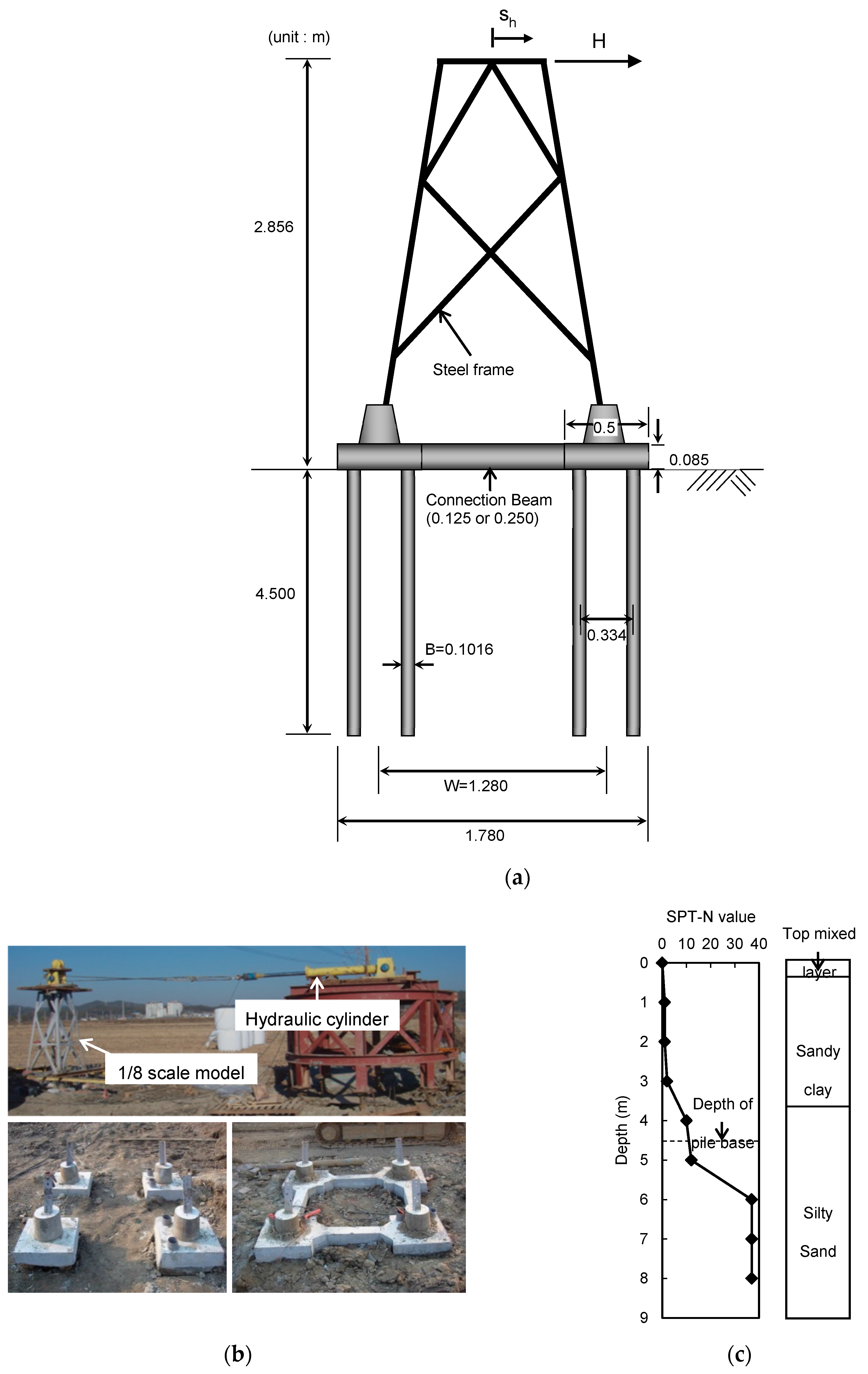
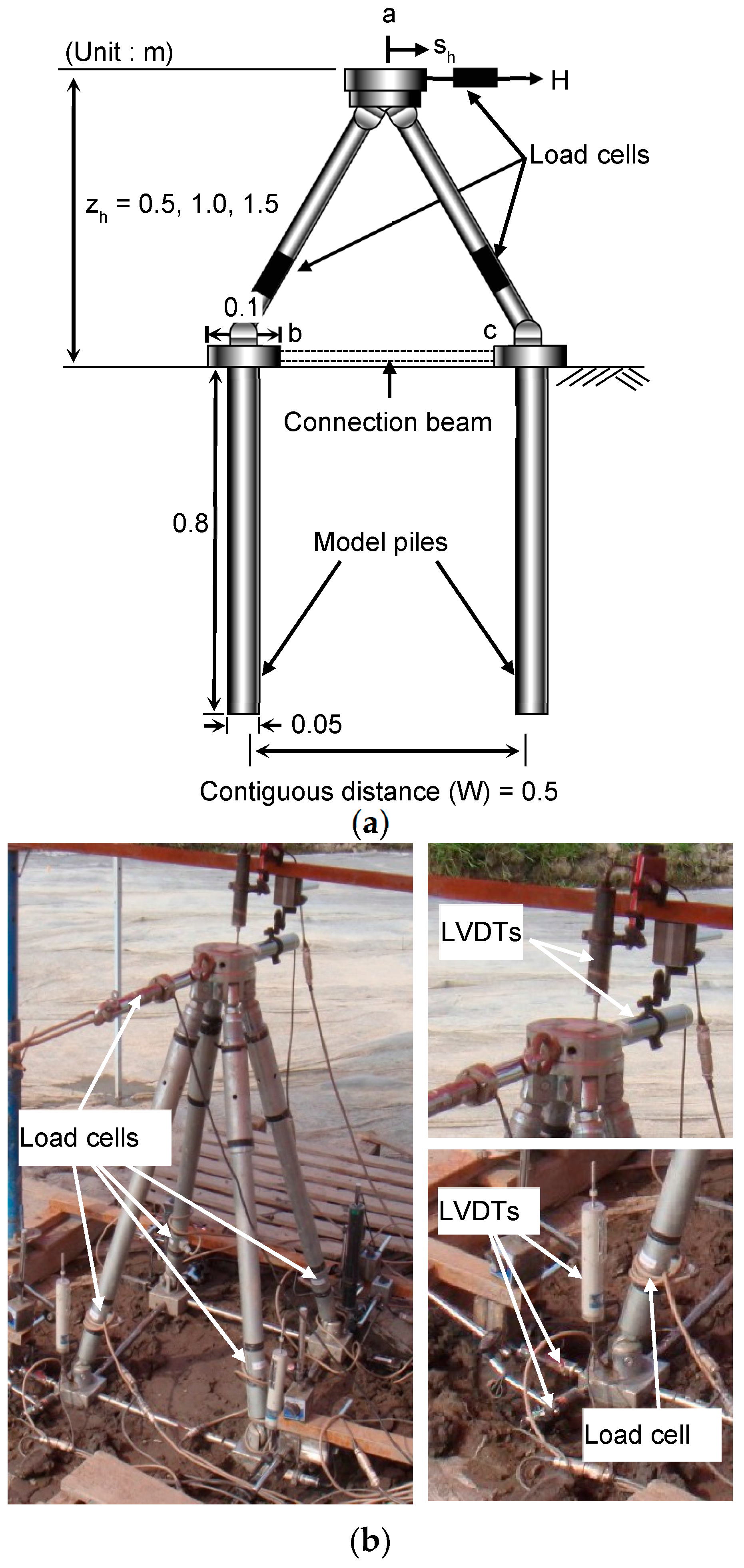
In this study, the performance of connected foundation for the electric transmission tower structures is investigated using a series of field load tests. For this purpose, model transmission tower structures using unconnected and connected foundations are manufactured and used in the field load testing program. For the model structures, connection beams with different stiffness are used to examine the effect of connection beams on overall performance of transmission tower foundations. Based on the test results, a design equation is proposed for the estimation of the load carrying capacity of connected foundations. Field load tests using the prototype models of transmission towers are also conducted to confirm the performance of connected foundations obtained from the model tests and to verify the proposed design method.

2. Transmission Tower Foundation

2.1. Types and Design Procedure

Various types of foundations are available for transmission tower structures primarily depending on soil conditions as described in Figure 1. Figure 1a,b shows embedded footings, also referred to as inverted-T foundation, and pile foundation, respectively, both of which are commonly used for the lattice types of tower structures. In soft soil areas, pile foundation is frequently adopted, although it is more costly than embedded footings. Figure 1d shows single pole foundation that is constructed in general as a form of drilled shafts or directly embedded piles with or without backfills. Connected foundation shown in Figure 1c is sometimes used with connection beams installed between individual foundations at each corner of tower. It is supposed that the installation of connection beams provides additional stiffness and resistance to entire foundation system [4,5,7]. Connected foundations are particularly effective when large differential settlements are expected or structural instability due to insufficient foundation resistance is an issue.
Figure 1. Types of foundations for transmission tower structures: (a) inverted-T foundation; (b) pile foundation; (c) connected foundation; and (d) single pole foundation
Sustainability 08 00030 g001
The types of design loads for transmission tower foundations differ depending on the type of transmission tower structure. For example, the single pole foundation shown in Figure 1d is designed primarily for lateral loads and overturning moments while vertical loads are regarded as minor because the self-weight of superstructure is relatively small. For the lattice types of transmission tower structures, lateral loads are assumed to govern the design. When lateral loads are imposed on the upper tower structure, the loads are transferred to the lower foundations, which act as either vertical compressive or uplift forces [1].
Figure 2 shows the typical configuration of applied load (H), transferred loads to lower foundations (Q) and mobilized foundation resistances (R). Given the loading direction in the figure, the front- and rear-side piles are indicated in Figure 2, which are subjected to compressive and uplift tensile forces, respectively. The stability of foundation is checked based on following relationship [6,8]:
Q v c R v c F S   and   Q v t R v t F S   in vertical direction
Q h c R h c F S   and   Q h t R h t F S   in horizontal direction
where Qvc and Qvt are transferred compressive and uplift loads on front and rear sides, respectively; Qhc and Qht are transferred horizontal loads on front and rear sides, respectively; FS is factor of safety; Rvc and Rvt are compressive and uplift resistances, respectively; and Rhc and Rht are horizontal resistances, respectively. While the stabilities in both vertical and horizontal directions must be guaranteed, the vertical stability against uplift loads (Qvt) usually governs the design as uplift resistances are usually smaller than vertical compressive resistances due to the absence of tip resistance and lower skin friction than for compressive case [9,10,11].
Figure 2. Configurations of loads and resistances for transmission tower structure.
Sustainability 08 00030 g002

2.2. Connected Foundation

Connected foundations for transmission tower structures consist of main foundation components and supplementary connection beams that are placed between the individual foundation components installed at each corner of tower without additional destruction of the environment. Connected foundations are effective when transmission tower structures are to be constructed in soft soil areas and large amounts of differential settlements are expected [1,6]. Figure 3 shows two different cases of loading conditions for foundations of laterally loaded transmission tower structures. Figure 3a represents the case where vertical compressive and uplift loads are dominant, which is possible if the load height (zh) in Figure 2 is very high leading to smaller horizontal loads transmitted to the foundations. Figure 3b represents the horizontal-load dominant case, which is possible for lower-heighted towers.
For the vertical-load dominant case in Figure 3a, the connection beams provide additional shear resistances against vertical displacement of the foundations resulting in increases in the load capacity and reduced differential settlements. For the horizontal-load dominant case in Figure 3b, the laterally loaded piles tend to rotate and the connection beams would generate downward and upward shear forces to the front- and rear-side foundations, respectively, with the effect of additional differential settlements. In reality, as the vertical loads often control the design of foundations for typical transmission tower structures, it is expected that the application of connection beams is positively effective to improve the performance of the tower structures.
Figure 3. Loading conditions with (a) vertical and (b) lateral load dominant cases.
Sustainability 08 00030 g003

3. Model Load Tests

3.1. Test Site and Soil Condition

In order to investigate the performance of connected foundations and effect of connection beams, a series of field load tests using model transmission tower structures was conducted. The test site was located near Iksan city in Korea where soft clayey soils existed. To characterize in-situ soil condition at the test site, the standard penetration test (SPT) and cone penetration test (CPT) were conducted. Figure 4 shows the depth profiles of SPT blow count N and CPT cone resistance qc with soil type. The top 1-m surface soil was silty sand, which was removed before the load tests. Below the top silty sand layer, silty clays extended down to the depth of 7.5 m, below which a hard silty sand layer existed.
Undisturbed soil samples were collected from the silty clay layer and tested to obtain various index and fundamental soil properties. The soils were classified into clay with low plasticity (CL) according to the unified soil classification system (USCS). The liquid limit (LL) and plasticity index (PI) were 44.9% and 23.3%, respectively. The total unit weight (γt), specific gravity (Gs), water content (w), and coefficient of compressibility (Cc) were 16.59 kN/m3, 2.69, 43.3%, and 0.4, respectively. The unconfined compression and unconsolidated undrained (UU) triaxial tests were also conducted and the undrained shear strength (su) was measured in 8.4 to 11.1 kPa range.
Figure 4. SPT and CPT results at test site.
Sustainability 08 00030 g004

3.2. Model Structures

Model transmission tower structures with different types of connection beams and tower heights were adopted in the load tests. Figure 5 shows detailed configuration of the model structures. The model transmission structures were designed in a simplified configuration with the upper tower structure and lower foundations. The upper tower structure was manufactured using steel tubular frames with four legs and joint head (”a” in Figure 5a). The lower foundations consisted of mats and model piles. Piles were considered as those are commonly used for the transmission towers in soft soils. The upper tower frames and lower foundations were all hinge-connected, as indicated at a, b, and c in Figure 5a.
Tower structures with three different heights (zh) were prepared. The considered load heights (zh) were 0.5, 1.0, and 1.5 m, corresponding to 1 W, 2 W, and 3 W, respectively, where W is contiguous distance equal to 0.5 m as indicated in Figure 5. For connected foundations, three different types of connection beams were used: (1) low-stiffness wire type with EI = 0.133 N·m2 (T1); (2) medium-stiffness beam with EI = 6.135 N·m2 (T2); and (3) high-stiffness beam with EI = 1571 N·m2 (T3). Detailed test conditions are summarized in Table 1.
The piles of the model structures were made of closed-ended steel pipes with diameter (B) of 50 mm and length of 800 mm. Between the model piles and the upper tower frames, 100 mm × 100 mm square-shaped steel mats were placed. A load cell was installed at the top joint head to measure applied lateral loads and four additional load cells were installed along the four tower frames to measure forces transmitted to the lower foundations. Fifteen LVDTs were installed at the joint head and on the four steel mats to measure vertical and horizontal displacements. The lateral loads were applied at the joint head using a wire-connected winch that was installed on a reaction H-pile driven at 20 to 30 m from the model structure.
Figure 5. Views of model transmission tower structure used in tests: (a) Detailed configuration and (b) Model structure and instrumentation
Sustainability 08 00030 g005
Table 1. Test conditions for model tests.
Foundation TypeEI a (N·m2)zh b (m)Test NameTest Model
Unconnected foundationNone (N)0.5 (1W)1W-N Sustainability 08 00030 i001
1.0 (2W)2W-N
1.5 (3W)3W-N
Connected foundation0.133 (T1)0.5 (1W)1W-T1 Sustainability 08 00030 i002
1.0 (2W)2W-T1
1.5 (3W)3W-T1
6.135 (T2)0.5 (1W)1W-T2 Sustainability 08 00030 i003
1.0 (2W)2W-T2
1.5 (3W)3W-T2
1571 (T3)0.5 (1W)1W-T3 Sustainability 08 00030 i004
1.0 (2W)2W-T3
1.5 (3W)3W-T3
a EI: stiffness of connection beam; b zh: load height.

4. Test Results

4.1. Load–Displacement Response

Lateral load–displacement (H-sh) curves measured at the top joint head are shown in Figure 6 for the cases with different connection beams of low (T1), medium (T2), and high (T3) stiffness for different tower heights (zh) of 0.5, 1.0, and 1.5 m, corresponding to 1W, 2W, and 3W, respectively. For comparison, the test results obtained from unconnected foundations were also included in Figure 6. Note that the magnitude of H decreases as zh increases due to higher overturning moments with increasing moment arm. The vertical dashed lines in Figure 6 indicate the loads and displacements corresponding to uplift pile displacements equal to 10% of pile diameter (0.1 B), as will be further discussed.
Figure 6. Lateral load-displacement curves of model transmission tower structures for different load heights (zh): (a) 1W; (b) 2W; and (c) 3W.
Sustainability 08 00030 g006
The load responses of the unconnected foundations in Figure 6 indicate that H increases up to certain load levels and then shows ranges of constant H values with no further increase in load capacity. As discussed previously, failure or ultimate condition of the transmission tower structures is governed by the uplift load capacity of rear-side piles. Once the uplift load capacity of rear-side piles is fully mobilized, load can no longer be increased whereas the compressive load capacity of front-side piles has not been fully mobilized yet.
From Figure 6, it is seen that connected foundations improved the load carrying capability, which appears different depending on the load height and stiffness of connection beam. For zh = 1 W in Figure 6a, no marked increase in load capacity is observed within the initial loading range. Once yielding is reached, the load capacity of connected foundations continuously increases without clear indication to failure. The increase in load capacity after yielding was more pronounced for higher-stiffness connection beams showing additional safety margin and ductility. For zh = 2 W and 3 W in Figure 6b,c the connected cases also showed improved load carrying capability. The effects of connection beam with chan

4.2. Design Criterion for Ultimate Load Capacity of Connected Foundations

Figure 7 shows the vertical (svc and svt) versus horizontal (shc and sht) displacements measured from the front-side compressive and rear-side uplift piles of unconnected and connected foundations. For the vertical displacements, svc and svt represent downward settlement and uplift displacement of the front-side and rear-side piles, respectively. The vertical and horizontal displacements of uplift piles (svt and sht) (solid lines in Figure 7a,b) are much larger than those of compressive piles (dashed lines in Figure 7a,b. It is also seen that uplift displacements (svt) are markedly larger than downward settlements (svc) and horizontal displacements (shc and sht) for both unconnected and connected foundations. This means that the uplift load capacity controls the load capacity of entire foundation system and thus ultimate load condition of transmission tower structures.
Figure 7. Vertical versus horizontal displacements of compressive front- and uplift rear-side foundations for (a) unconnected and (b) connected foundations.
Sustainability 08 00030 g007
The ultimate load capacity of axially loaded piles is often specified as a load corresponding to 0.1 B settlement (i.e., 10% of pile diameter) assuming that it corresponds to the level of differential settlement that would cause the ultimate limit state of superstructure. In a similar concept, design criterion for transmission tower foundations can be given by the 0.1 B condition for uplift displacement based on the results in Figure 7. In fact, the uplift load capacity of piles would be fully mobilized at displacements smaller than 0.1 B. For connected foundations, as observed in Figure 6, the load capacity of transmission tower structures tends to continuously increase even after 0.1B condition of uplift piles due to additional load carrying mechanism of connection beams. Therefore, the adoption of 0.1B criterion for uplift piles is reasonable for connected foundations in that typical tolerable differential settlement and the load response characteristics of connected foundations can both be reflected.

4.3. Effect of Connection Beams

Figure 8a shows the values of the ultimate lateral load Hu acting on the transmission tower for connected and unconnected foundations with different connection beam stiffness and load heights. From Figure 8a, it is seen that Hu increases similarly with increasing connection beam stiffness for all load heights. However, it is also observed that the use of connection beam is more effective for higher load heights when the ratio of Hu between unconnected and connected cases is considered.
The reduction of differential settlement is another main aspect that is expected from the use of connected foundation. Figure 8b shows the values of differential settlement (Δsv) measured for different connection beam. The values of Δsv in Figure 8b corresponds to those measured at the loads equal to Hu for unconnected foundation cases. Δsv decreases as connection beam stiffness increases while the magnitude and rate of Δsv decrease differ for different load heights. For the low (T1) and high (T3) stiffness connection beams, Δsv decreased by 16% to 50% and 44% to 97%, respectively, showing higher reduction effects of differential settlement for higher connection beam stiffness.
Based on the results in Figure 8b, the main effects of connection beam on differential settlement can be summarized as follows: (1) the effect of connection beam is not linearly proportional to connection beam stiffness, showing decreasing rate of the reduction effect with increasing connection beam stiffness; and (2) the reduction effect of differential settlement is more pronounced for higher load height, again indicating that the use of connected foundation is more effective for higher tower structures.
Figure 8. Changes of ultimate load capacity and differential settlement with connection beam condition: (a) ultimate load capacity (Hu) and (b) differential settlement (Δsv).
Sustainability 08 00030 g008

5. Design Application

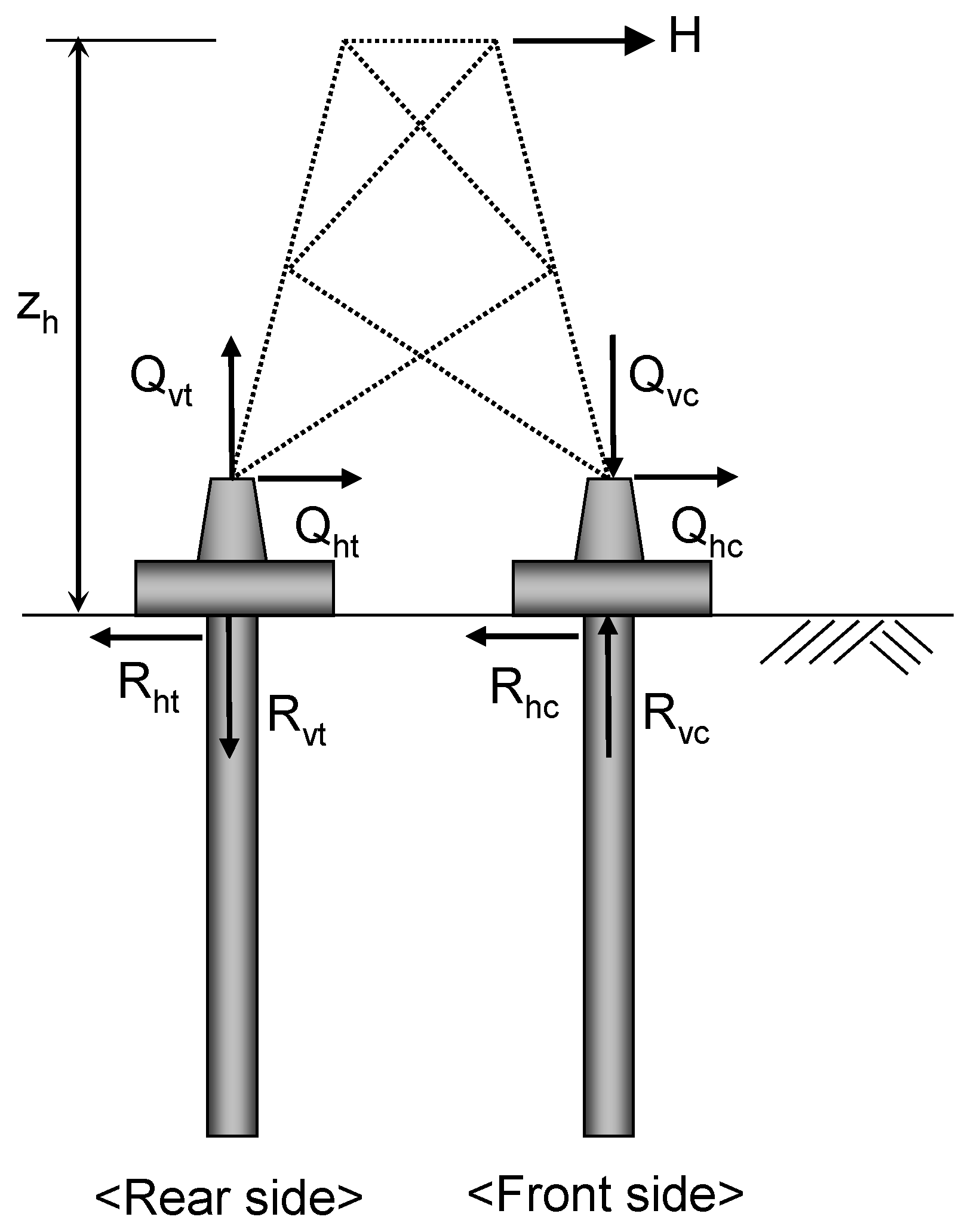
As indicated in Equations (1) and (2), the maximum load (Hu) applicable to the transmission tower is given as a function of the vertical or horizontal resistance (Rv or Rh) of the individual foundation components. Considering the equilibrium condition of entire structural system in Figure 2, Hu can be estimated as follows:
H u = ( 2 R h t + 2 R h c ) / F S = 4 R h / F S
H u = 2 R v t W z h 1 F S
H u = 2 R v c W z h 1 F S
where Rvc and Rvt are compressive and uplift resistances, respectively; Rhc and Rht are horizontal resistances; FS is factor of safety; and W and zh are contiguous distance and load height, respectively. The smallest Hu is determined from Equations (3)–(5), which would then control the design. For most cases of transmission tower structures, Rvt is smallest and Equation (4) tends to control the design.
Connected foundations show higher load carrying capability due to additional resistances provided by connection beams. Increase in the uplift resistance (Rvt) for connected foundations can then be expressed in terms of that for unconnected foundation as follows:
R v t , c = C R R v t
where Rvt,c and Rvt are uplift resistances of connected and unconnected foundations, respectively, and CR is the resistance increase factor. Introducing the resistance increase factor CR, the ultimate lateral load of Equation (4) can be rewritten as follows:
H u , c = 2 C R R v t W z h 1 F S
where Hu,c is ultimate lateral load capacity for connected foundations; Rvt is uplift resistance; and CR is resistance increase factor.
In order to evaluate the values of 
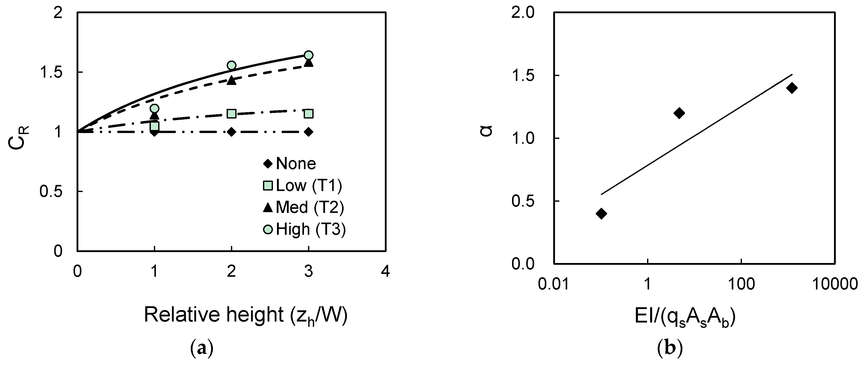
CR, the correlation analysis was performed using the model load test results. Key variables adopted into the correlation analysis are load height, stiffness of connection beams, and soil condition, which were found as affecting the load carrying capability of connected foundations from the test results. The result of correlation analysis. given in Figure 9a,b. shows the influence of load height and connection beam stiffness, respectively. From Figure 9a, it is seen that CR increases with connection beam stiffness and loading height. The correlation given in Figure 9a is:
C R = 1 + α × z h / w 3.36 + 1.05 ( z h / w )
where α is stiffness-related model parameter. The values of α were found to be 0.4, 1.2, and 1.4 for low (T1), medium (T2), and high (T3) stiffness cases, respectively, indicating variability with connection beam stiffness.
The effect of connection beam stiffness given in terms of CR would change with soil condition as the load capacity of foundations depends on soil condition, which needs to be properly taken into account. The values of α in Equation (8) were therefore evaluated considering the connection beam stiffness (EI) normalized with the uplift pile load capacity given by pile skin friction (qs), pile shaft area (As), and pile base area (Ab). Note that Ab and As eventually represent the load capacity of foundation, while qs reflect the local soil condition. The values of α were obtained from the model test results and plotted in Figure 9b as a function of the normalized stiffness. The correlation given in Figure 9b is:
α = 0.1015 × ln ( E I q s A s A b ) + 0.784
where EI is connection beam stiffness; qs is pile skin friction; and As and Ab are pile shaft and base areas, respectively. The summation in Equation (9) represents the cases where multiple piles are used. Ab was introduced to make α as a dimensionless, normalized parameter. Using Equations (8) and (9), the values of CR can be obtained and applied to estimate the load carrying capacity of connected foundations.
Figure 9. Correlation for resistance increase factor: (a) Resistance increase factor (CR) versus relative height and (b) Correlation parameter versus normalized stiffness.
Sustainability 08 00030 g009

6. Field Load Tests Using Prototype Models

6.1. Test Description

The performance of connected foundations and proposed design method were obtained from the test results using small-scale model structures. To check and validate these results and proposed design method, additional field load tests were conducted using larger-scale prototype models of transmission tower structures. The prototype models were designed and constructed with 1/8 scale in reference to the 345 kV transmission line in Korea. The field load tests were conducted at Hwasung city located near the west coastal area of Korea. Soils at the test site consisted of the upper sandy clay layer with 4-m thickness and the lower silty sand layer. The upper sandy clay was classified into CL showing a soft soil condition with SPT N values smaller than 2. The total unit weight (γt), water content (w), liquid limit (LL), plastic index (PL), and compressive index (Cc) for the upper sandy clay layer were 15.5 kN/m3, 69.6%, 55.9%, 29.2%, and 0.58, respectively. The undrained shear strength (su) at the middle depth of the upper sandy clay layer was 8.6 kPa.
Figure 10 shows the detailed configuration of prototype models used in the field load tests. The prototype model structures with and without connection beams were both constructed and tested. The upper tower structures were constructed using lattice steel frames with the height of 2.856 m corresponding to 2.23 times the contiguous distance (W) equal to 1.28 m (i.e., 2.23 W). For the foundations at each corner, four close-ended piles and square concrete mat of 0.5 m × 0.5 m were installed. The piles were 101.6 mm and 4.5 m in diameter and length, respectively, driven down to the top of the lower silty sand layer. Two different concrete connection beams with widths of 125 and 250 mm were used. These correspond to connection beam stiffness (EI) equal to 25% and 50% of the mat stiffness. A total of three prototype model structures were constructed and tested, including one unconnected foundation and two connected foundations with 25% and 50% of stiffness connection beams. These will be referred to as PMT-N, PMT-25, and PMT-50, respectively. Lateral loads (H) were applied at the top of the tower using the hydraulic cylinder with a load increment of 50 kN (Figure 10b). The load cell was installed between the hydraulic cylinder and the transmission tower to measure applied lateral load (H). On the foundations at each corner, LVDTs were installed to measure displacements of foundations.
Figure 10. Configuration of prototype model and foundations for field load tests: (a) Overall view of prototype model; (b) Test setup; and (c) Soil conditions.
Sustainability 08 00030 g010

6.2. Comparison and Validation

Figure 11a shows lateral load-displacement (H-sh) curves measured at the top of the prototype model tower structures. Similar to the small-scale model tests, connected foundations showed higher load carrying capacities than unconnected foundation. The load carrying capacity increase as the connection beam stiffness increases. Based on the 0.1B criterion, the values of Hu/Hu,un were obtained and compared with those obtained from the small-scale model tests (SMT) in Figure 11b. Hu increased by 56.9% and 75.5% for the 25% and 50% of stiffness connection beams, respectively. As in SMT, the increase in Hu is not linearly proportional to connection beam stiffness, showing decreasing rate of Hu increase after the 25% connection-beam stiffness. Figure 11c shows the ratios of differential settlements between connected and unconnected foundations (∆sv/∆sv,un). ∆sv decreased by 88% and 94% for the 25% and 50% of stiffness connection beams, respectively. It is also seen that the reduction of ∆sv is relatively small after the 25% connection-beam stiffness, indicating that the 25%-stiffness connection beam may be more efficient in this case.
To check the validity of the proposed design equations of Equations (8) and (9), the values of Hu were calculated and compared with measured results. Figure 12 shows the calculated (Hu,cal) and measured (Hu,mea) results. For the calculation of Hu,cal, the pile skin frictions (qs) was obtained using the α method of API [12]. The values of CR estimated using the proposed method were 1.76 and 1.79 for the 25% and 50% of stiffness connection beams, respectively. As compared in Figure 12, the calculated value of Hu,cal are in good agreement with measured values of Hu,mea, confirming the validity of the proposed method.
Figure 11. Results from prototype model load tests: (a) Load-displacement curves; (b) Load capacity ratio (Hu/Hu,un); (c) Differential settlement ratio (∆sv/∆sv,un).
Sustainability 08 00030 g011
Figure 12. Comparison of measured (Hu,mea) and calculated (Hu,cal) lateral load capacities from prototype model tests.
Sustainability 08 00030 g012

7. Summary and Conclusions

The sustainability of electrical energy supply system has become a critical issue as the demand for electricity has continuously increased. The connected foundation is an effective foundation type to increase the sustainability of electrical transmission tower system in soft soils without additional environmental destruction. In this study, the performance of connected foundation for transmission tower structures was investigated using a series of field load testing programs. For this purpose, model transmission tower structures were specifically manufactured and adopted into the field load tests. Variety of test conditions with different connection beam stiffness and load heights were considered in the model load tests. Based on the load-capacity mobilization mechanism, a criterion to define the ultimate load capacity (Hu) for connected foundations was proposed.
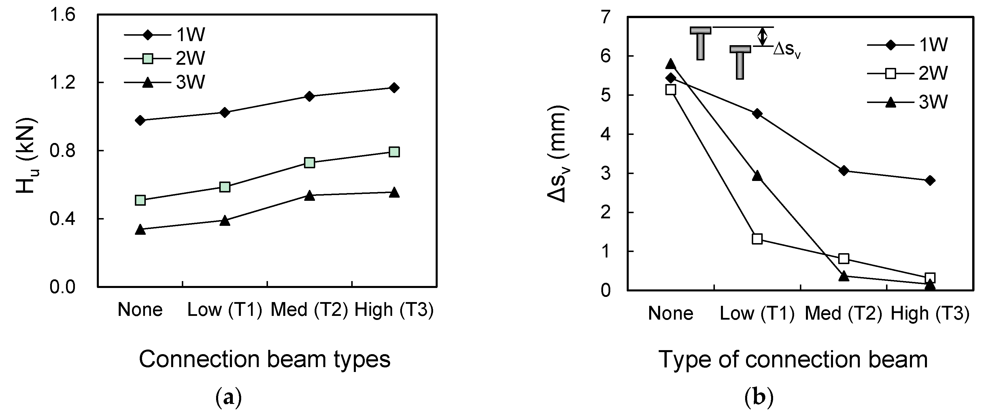
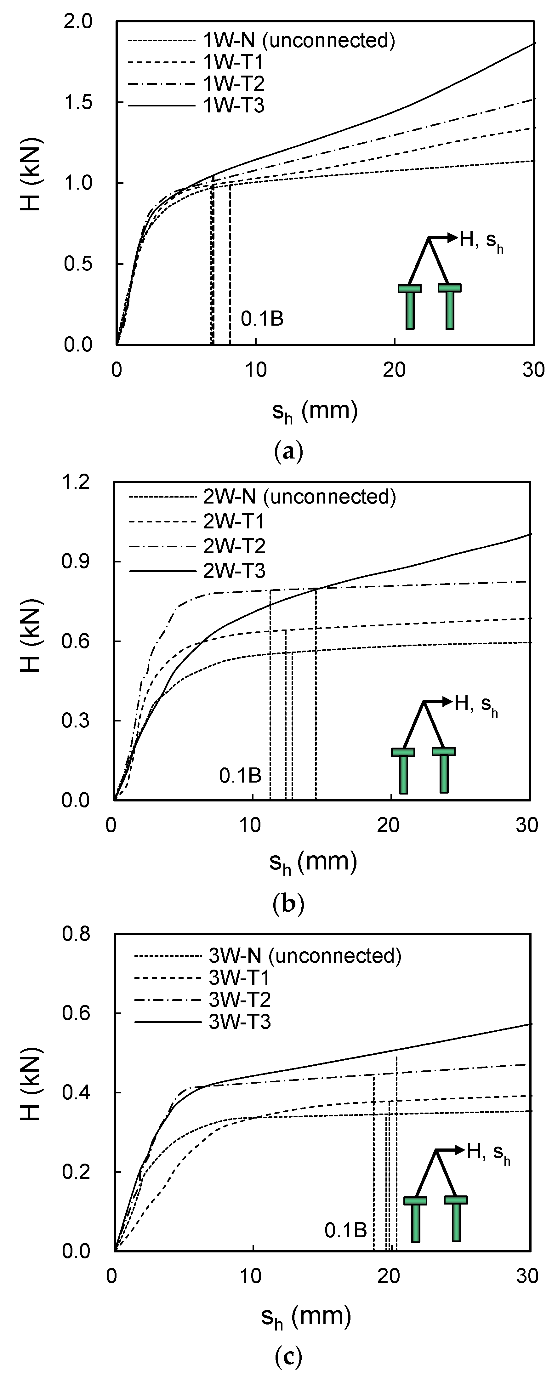
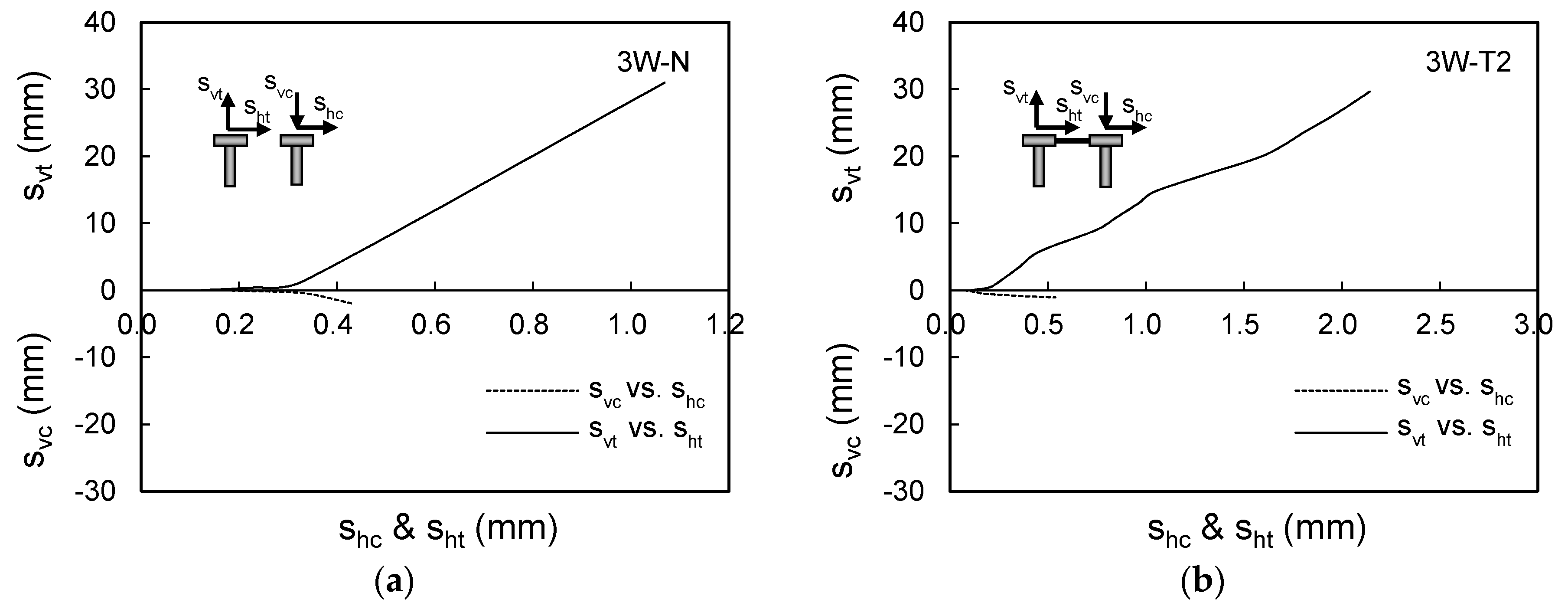
For all test conditions considered in this study, connected foundations produced better performance with higher load carrying capacities and smaller differential settlements than unconnected foundations. In particular, the use of connection beam was more effective for higher load heights. The load carrying capacity of connected foundation increased with increasing connection beam stiffness. Based on the test results, a design method to estimate the load capacity of connected foundation was proposed with the correlation of resistance increase factor. The effects of load height, connection beam stiffness, and soil condition were taken into account for the proposed design method. The proposed method can be effectively applied to improve the foundation stability of electrical transmission tower structures in soft soils.
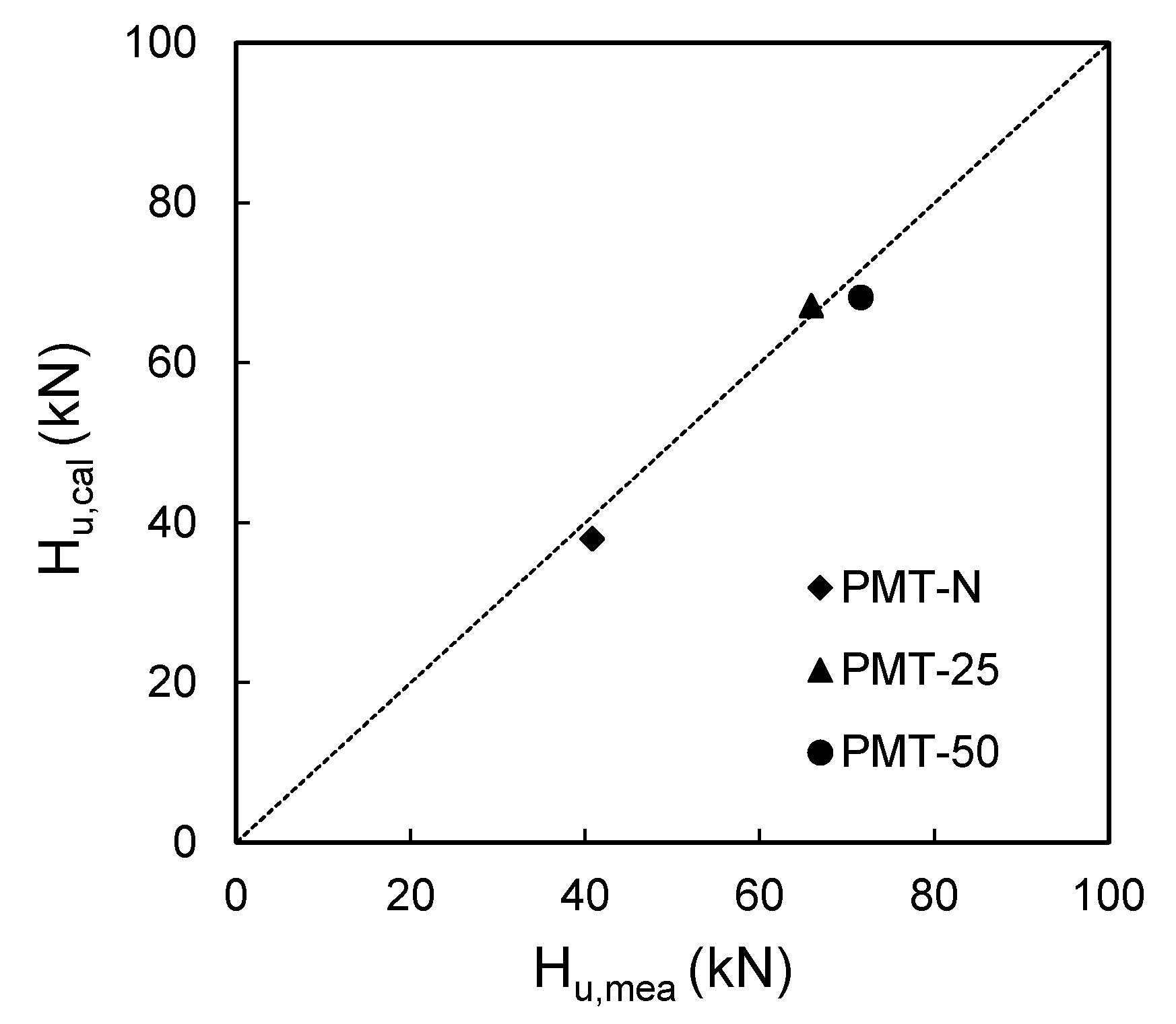
Field load tests using prototype models of transmission tower structure with reduced scale were conducted to check the performance of connected foundations and the validity of proposed design method. Two connection-beam stiffness of 25% and 50% mat stiffness were considered for the prototype model structures. Hu of connected foundations increased by 56.9% and 75.5% for 25% and 50% of stiffness connection beams, respectively. Differential settlements decreased by 88% and 94% for 25% and 50% of stiffness connection beams, respectively. The calculated load carrying capacity using the proposed design method showed good agreement with measured results confirming the validity of the proposed method.

Acknowledgments

This work was supported by a Power Generation & Electricity Delivery of the Korea Institute of Energy Technology Evaluation and Planning (KETEP) grant funded by the Korean Ministry of Knowledge Economy (No. 20101020200060). This work was also supported by the Basic Science Research Program through the National Research Foundation of Korea (NRF) grant funded by the Korean government (MSIP) (Nos. 2011-0030040 and 2013R1A1A2058863).

Author Contributions

All three authors significantly contributed to the scientific study and writing. Doohyun Kyung and Junhwan Lee contribute to the overall idea, planning, financing, analyzing and writing of the manuscript; Daehong Kim contributed to the overall idea, planning and financing of the project; and Garam Kim and Incheol Kim contributed to discussions on the mechanical issues of this paper and manuscript preparations.

Conflicts of Interest

The authors declare no conflict of interest.

References

  1. Institute of Electrical and Electronics Engineers. IEEE guide for transmission structure foundation design and testing. Available online: http://ieeexplore.ieee.org/servlet/opac?punumber=7707 (accessed on 9 September 2015).
  2. Morinaga, Y.; Kamiji, M.; Imoto, S.; Ogawa, S.; Iwamori, K. Transmission tower foundation in japan. In Proceedings of IEEE/PES Transmission and Distribution Conference and Exhibition 2002: Asia Pacific, Yokohama, Japan, 6–10 October 2002; pp. 2162–2165.
  3. Korea Electrical Contractors Association. Handbook for Transmission Structure; Korea Electrical Contractors Association: Seoul, Korea, 2003. [Google Scholar]
  4. Jang, S.H.; Kim, H.K.; Ham, B.W.; Chung, K.S. A study on the transmission tower foundation design and construction method—A focus of cylindrical foundation. Trans. Korean Inst. Electr. Eng. 2007, 56, 1031–1034. [Google Scholar]
  5. Kim, J.B.; Cho, S.B. The design and the full load test results of 765kV tower foundation. In Proceedings of Korean Institute of Electrical Engineers (KIEE) Fall National Conference, Yongin, Korea, November 1995; pp. 447–449.
  6. TEPCO. Design Guideline for UHV Foundation; Tokyo Electric Power Company: Tokyo, Japan, 1988. [Google Scholar]
  7. Japanese Electrotechical Committee. Design Standard for Power Transmission Supports, JEC-127–1979; Standard of the Japanese Electrotechnical Committee: Tokyo, Japan, 1997. [Google Scholar]
  8. Korea Electronic Power Corporation (KEPCO). Standard of the Tower Foundation Design in Transmission Line, DS-1110; Korea Electronic Power Corporation: Naju, Korea, 2011. [Google Scholar]
  9. Poulos, H.G.; Davis, E.H. Pile Foundation Analysis and Design, 1st ed.; John Wiley and Sons: New York, NY, USA, 1980. [Google Scholar]
  10. De Nicola, A.; Randolph, M.F. Tensile and compressive shaft capacity of piles in sand. J. Geotech. Eng. 1993, 119, 1952–1973. [Google Scholar] [CrossRef]
  11. Elhakim, A.F.; Mayne, P.W. Discussion of “Side resistance in piles and drilled shafts” by Michael W. O’Neill. J. Geotech. Geoenviron. Eng. 2002, 128, 448–449. [Google Scholar] [CrossRef]
  12. American Petroleum Institute. Recommended Practice for Planning, Designing and Construction Fixed Offshore Platforms. Working Stress Design; American Petroleum Institute: Washing, DC, USA, 1993. [Google Scholar]

