1. Introduction
Interest in efficient and eco-friendly management has been growing in recent years, especially in systems characterized by large consumption of non-renewable energy. Fluid handling systems, such as pump and fan systems are responsible for a significant part of total electrical energy use [
1]. As reported by Bene
et al. [
2], the electrical energy used to pump water is a significant portion of the total operational costs of the system. Recently, the energy efficiency of these systems has become more important as the political and ecological pressure to reduce energy consumption has increased [
3].
Pumping systems account for nearly 20% of the world’s energy used by electric motors and 25% to 50% of the total electrical energy usage in certain facilities. In district heating stations, the heat carrier is circulated between the energy source and consumers using pumps. Pumping energy is often one of the larger cost elements and may dominate a pump’s life cycle costs, especially if pumps run for more than 2000 h per year. There is a large potential to reduce electricity consumption through proper design and selection of pumping systems and controls. The number, the position and the technical characteristics of these pumps are established according to the chosen type of the heating system, the thermal power and the operating regime.
The main goal in operating a heating system is to provide the consumers with the heat demand according to outdoor climatic parameters. Thus, the heating system has a control system, which can be qualitative, quantitative or mixed. The quantitative adjustment requires a variation of the flow rate during operation, while keeping the hot water supply temperature constant.
Pumping applications with a variable flow rate typically use a throttling valve, a bypass line, and/or variable rotational speed to deliver the desired discharge. Flow control by valve throttling wastes energy by diverting excess flow through a bypass or by restricting the pump discharge. Additionally, valves can be a source of emissions and suffer corrosion, erosion, plugging, sticking, cavitations and leakage.
Adjustable speed drives provide an efficient flow control alternative by changing the pump speed. Variable-speed pumps (VSPs) allow continuous control over the hot water pressure according to the thermal load at a certain moment. Operating at reduced speeds results in other benefits as well, such as lower bearing loads, improved reliability, lower maintenance costs and decreased fugitive emissions by eliminating the control valve and the associated piping.
During the past several decades, the costs of variable-speed drives (VSDs) have come down significantly due to advances in technology, which allowed widespread applications of VSPs in water distribution systems and in building air conditioning systems. An increased issue in using VSP systems is the control and optimization of their operation and the total efficiency of the electric motor/pump arrangement under a given operating condition.
In terms of enhancing the operating efficiency, improving the control robustness and prolonging the service life, many practitioners in control engineering have spent great effort on energy efficient control and operation of VSPs during the last two decades [
4,
5,
6,
7,
8]. A number of researchers in the heating, ventilation and air conditioning (HVAC) field have also devoted considerable effort to developing and applying proper and optimal control algorithms for VSPs to enhance their energy efficiency [
9,
10,
11,
12,
13,
14]. The results show that the control strategy is robust and capable of improving the energy efficiency of the system for most of the scenarios considered (combinations between variable and fixed speed pumps, pumps with different power, speed, and characteristic curves). The adjustment possibilities of technological parameters and energy savings through pump and fan speed control was studied by Suceveanu [
15] and Georgescu [
16].
This paper provides a comprehensive discussion about pump control in heating stations and analyzes the energy efficiency of flow control methods. Specific attention is also given to selection of motor types, sizing and pump duty cycles. A comparative energy analysis is performed on the hot water discharge adjustment using throttling control valves and variable-speed drives in a district heating station constructed in Romania. To correlate the pumped flow rate with the heat demand and to ensure the necessary pressure using minimum energy, an automatic system has been designed. The performances of these control methods are evaluated in two practical applications. Additionally, some modernization solutions to reduce the environmental impact of heating stations are described.
2. Thermal Load of the Heating Station
Heating stations are designed to meet the consumers’ energy need in the coldest period of the year. However, most of the energy demand is much lower than the designed value of the heating station thermal load.
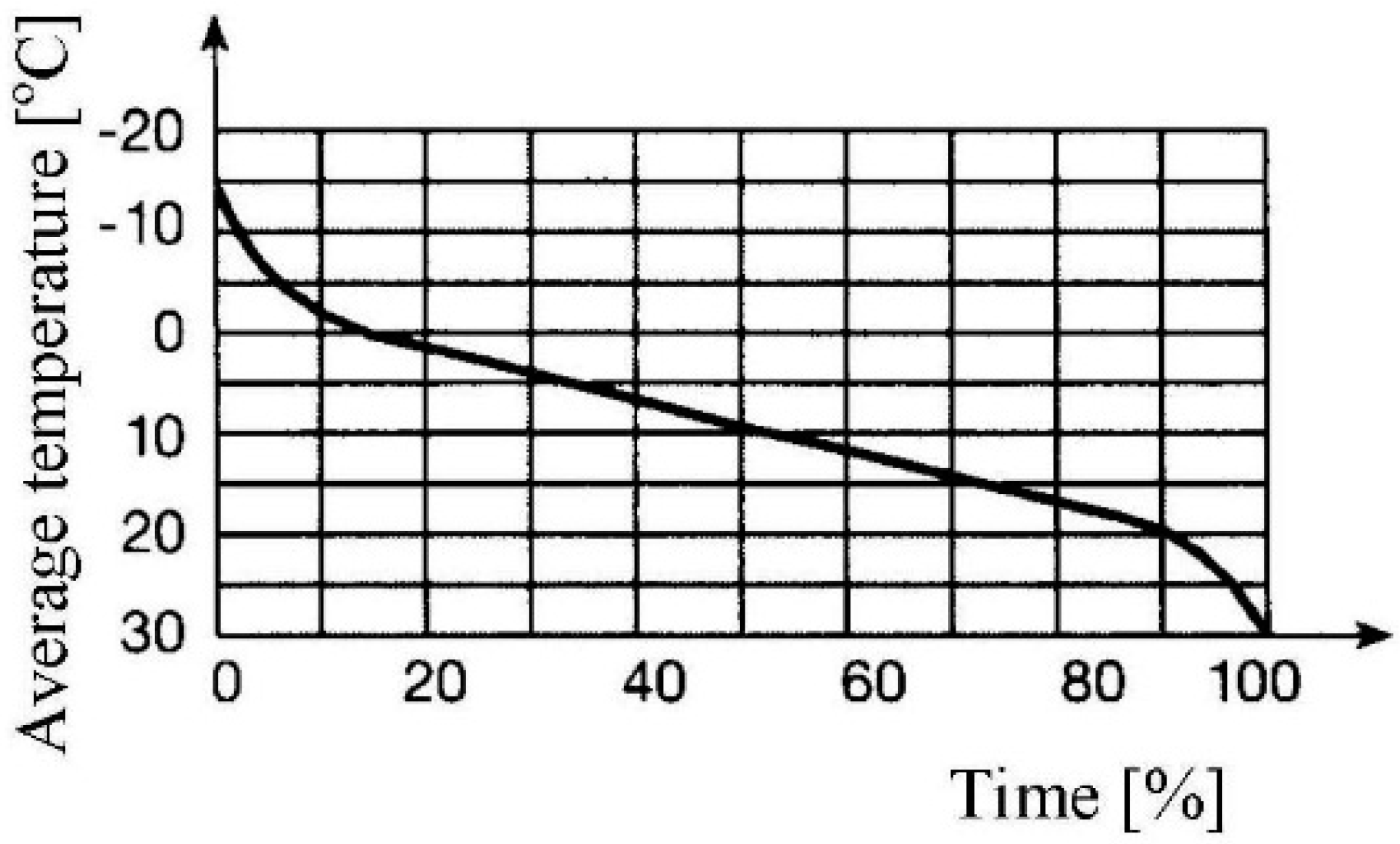
Figure 1 shows the yearly distribution of the daily average outdoor air temperature [
17]. The diagram shows that, throughout the year, the lowest temperatures represent approximately 5%. Thus, if the heating station is designed to cover the maximum energy need, then 95% of the year, the station is oversized. At the same time, for approximately 25% of the year, the average temperature is higher than +15 °C. Thus, for 25% of the year, the thermal energy provided by the heating station is used only to produce domestic hot water, which needs only a small portion of the installed capacity of the heating station.
Figure 1.
Daily average outdoor air temperature distribution throughout the year.
Figure 1.
Daily average outdoor air temperature distribution throughout the year.
For a constant difference between the supply and return temperatures of the hot water, the delivered energy does not vary proportionally with the discharge. Generally, at constant supply temperature, the return temperature is lower when the heat demand decreases.
The main goal in operating a heating system is to provide the consumers with the heat demand according to outdoor climatic parameters. Thus, the heating system is provided with an adjustment system, which can be qualitative, quantitative or mixed.
The quantitative adjustment requires varying the flow rate during operation, while keeping the hot water parameters constant. This can be done by (1) fixed-speed pumps (FSPs) with different technical characteristics or (2) variable-speed pumps (VSPs).
Some heating stations comprise fixed-speed hydraulic pumps arranged in parallel and discharge controlled by the number of pumps in operation. The cost related to pump operation can be reduced by decreasing the energy consumption. An attractive alternative to reach this target is the use of VSPs instead of FSPs.
3. Solutions for Reducing the Pumping Energy
The power absorbed
P, in kW, by a pump at a certain rotational speed is given by [
18]:
in which:
where γ is the specific weight of water, in N/m
3;
Q is the pump flow rate, in m
3/s;
Hp is the pump head for the operating point, in m; η is the general efficiency of the pumping station; and
wp is the specific pumping energy, in kWh/m
3.
3.1. Pump Operation at Fixed Speeds
Pumps used in heating stations are often centrifugal pumps, which are characterized by a head-flow (
H-
Q) curve that remains sufficiently flat for a wide range of flows. If the pump used is an FSP, the operating point is forced to move along the pump curve corresponding to the fixed nominal speed. There are two methods to vary the water discharge in a pipe network with an FSP:
- –
Bypassing part of the water discharge (the pump operates at the same pump head, water flow rate increases and the absorbed power also increases).
- –
Introducing a supplementary pressure loss using a control valve (the operating point is heading towards the left on the
H-
Q curve) [
19,
20].
Although the water discharge adjustment using the control valve can lead to higher energy efficiency of the water distribution system when the nominal pump head is lower than the optimal value, this method has the following disadvantages:
- –
increased wear of the control valve throttling elements;
- –
noise, vibrations and hydraulic impacts with negative effects in the system; and
- –
low operation reliability of the pumps.
3.2. Pump Operation at Variable Speeds
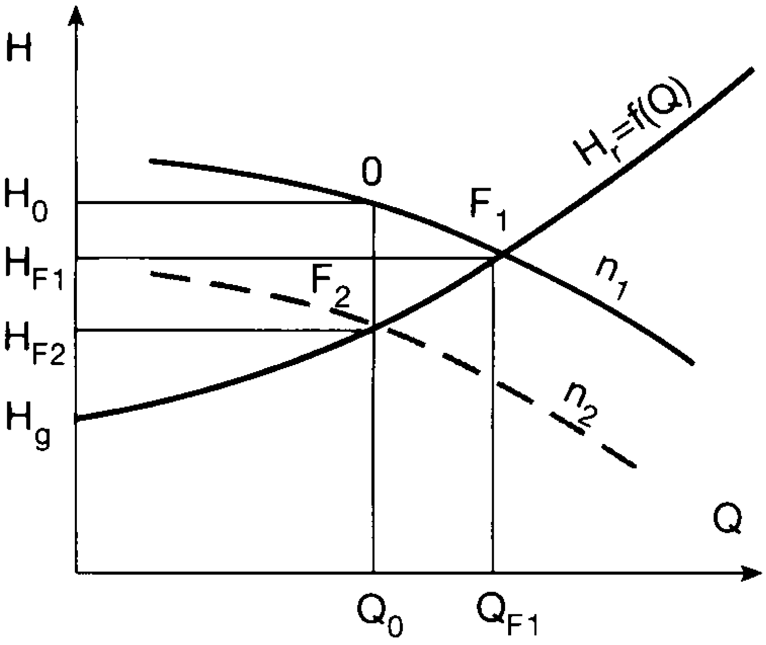
The best method to obtain a variable water flow rate is the use of variable-speed pumps. The flow control (
Figure 2) is achieved by changing the pump curve
H (at different pump speeds
n1 and
n2) on the fixed system curve
Hr. Pipework curve
Hr start from point (0,
Hg), where
Hg is the geodesic head. The operating point F
2 corresponds to the reduced pump head
HF2.
Figure 2.
Flow adjustment using pump speed control.
Figure 2.
Flow adjustment using pump speed control.
The relationships that link the pump characteristics (flow
Q, head
H, and power
P) operating at different speeds (
n1,
n2) are described by the affinity laws:
The approximation introduced into the power-speed relation implies that the efficiency will remain constant for speeds
n1 and
n2,
i.e., the efficiency curve will only be shifted to the left in the case of speed reduction. Equation (6) provides an analytical relationship between two different speeds (
n1 and
n2) and the corresponding efficiencies (η
1 and η
2) [
18]:
Therefore, as indicated by Sarbu and Borza [
18], the changes in efficiency can be neglected if the changes in speed do not exceed 33% of the nominal pump speed; this approximation is particularly justified for large pumps.
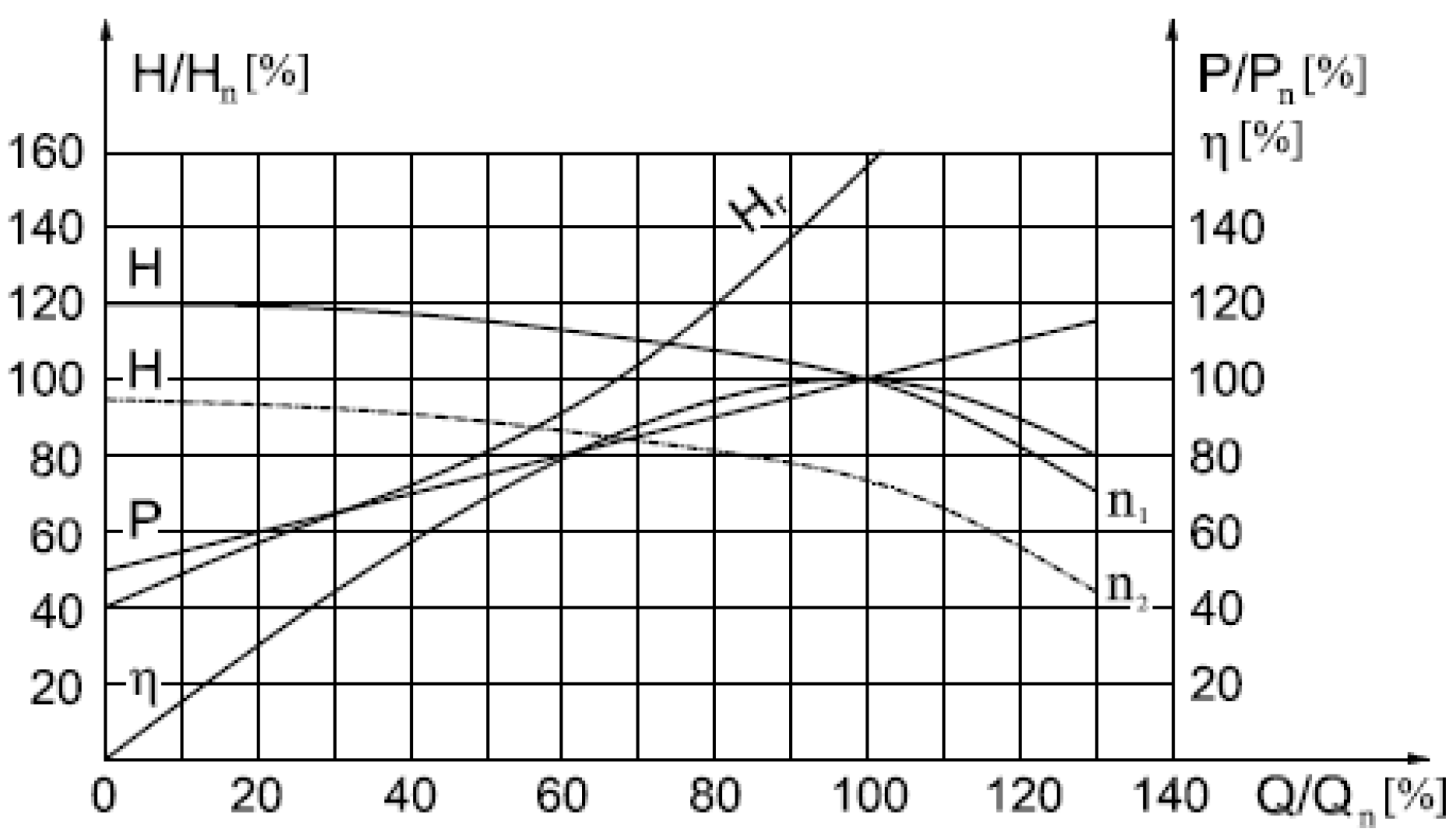
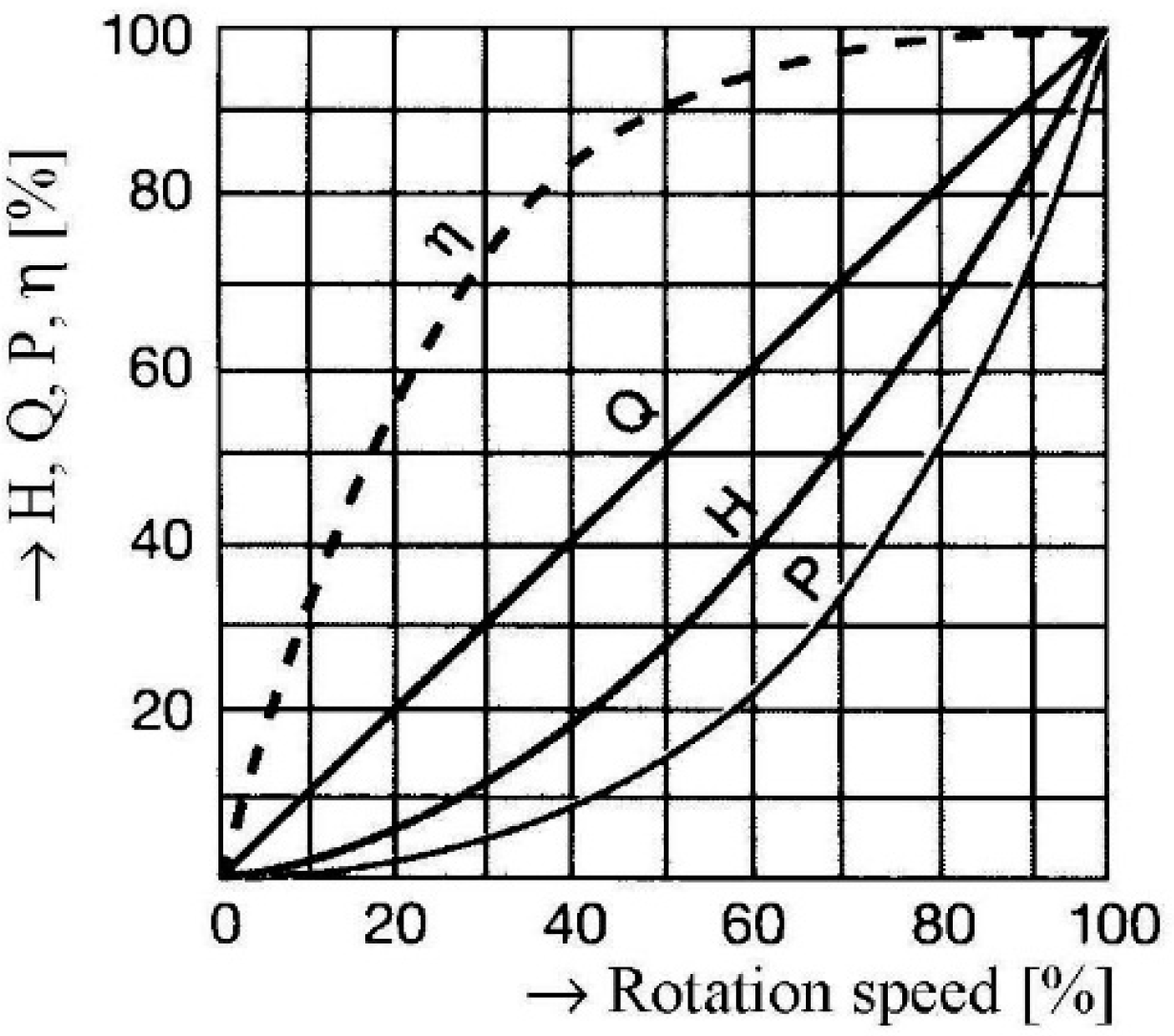
Figure 3 shows the variation curves of
H,
Q,
P, and η for centrifugal pumps depending on pump speed
n. A 20% reduction of the pump speed will decrease the power demand by 50% at constant pump efficiency. Thus, the possibility exists to reduce the pumping energy consumption by using variable-speed drives (VSDs).
In systems with high friction loss, the most energy-efficient control option is an electronic VSD, commonly referred to as variable frequency drive (VFD). The most common form of VFD is the voltage-source, pulse-width modulated (PWM) frequency converter (often incorrectly referred to as an inverter). The principal duty of the VFD is to alter the main supply to vary the speed of the electric motor while delivering the required torque at a higher efficiency. As a result, as the pump speed changes, the pump curve is adjusted for different operating conditions. The main advantages of variable-speed pumps are seen when the operating conditions in the system are characterized by a high variability.
Figure 3.
Variation of the centrifugal pump curves.
Figure 3.
Variation of the centrifugal pump curves.
Pumping systems with a widely varying flow rate demand are often implemented using parallel pumps [
21,
22]. If several pumps are to operate in parallel, the rotational speed can be modified for a single pump (while the other pumps operate at nominal speed and nominal discharge), and the frequency converter automatically connects to the other pumps.
To correlate the pumped flow with the heat demand and to ensure the required pressure using minimum energy, an automatic pump speed control device was designed (
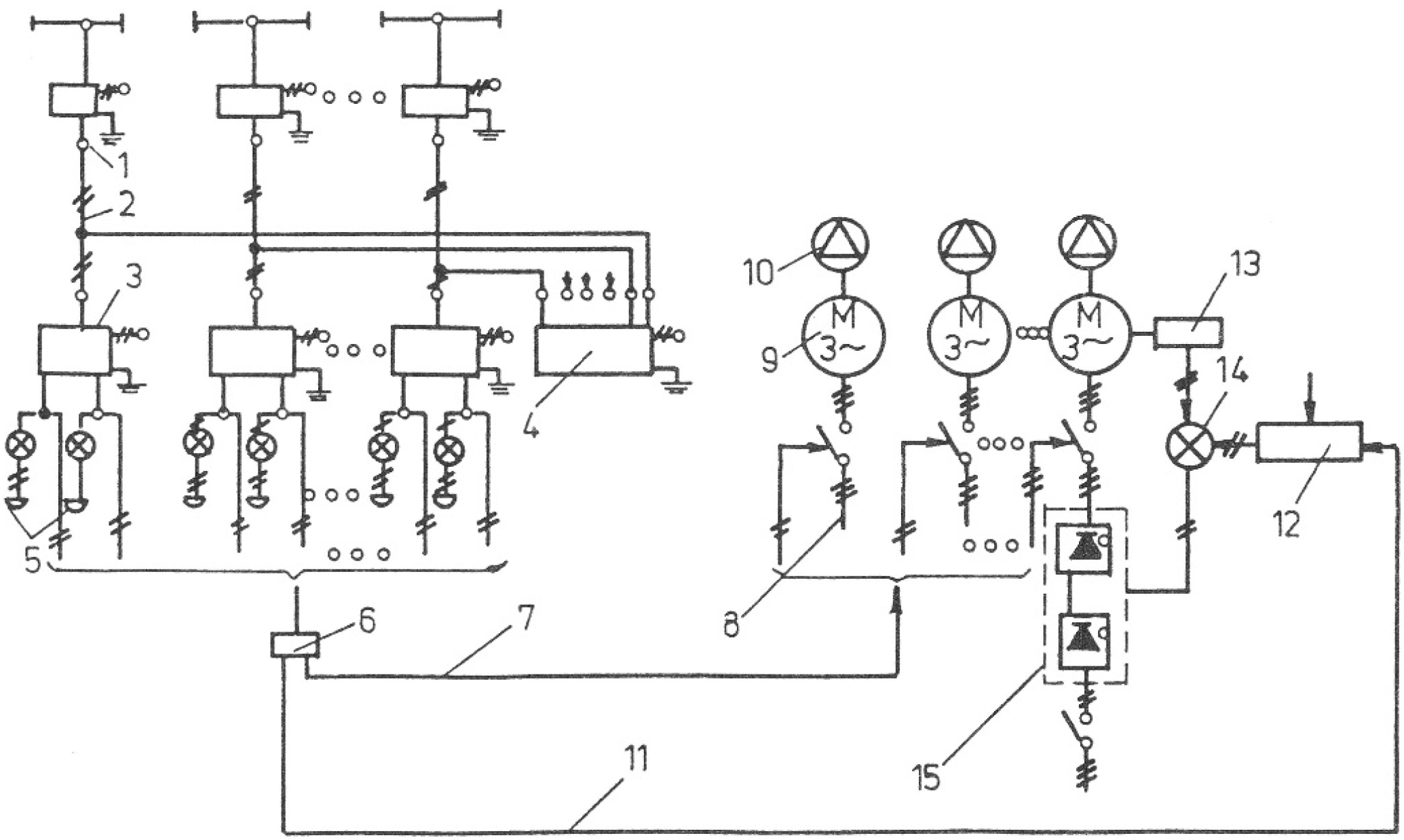
Figure 4), which is composed of an asynchronous electric motor with a breakdown rotor associated with a static frequency converter (with thyristor). The command given by the pressure controller is taken by the frequency converter, assisted by a process computer.
Figure 4.
Schematic of the automatic device for pump speed control using VFDs.
Figure 4.
Schematic of the automatic device for pump speed control using VFDs.
Electronic pressure transducers FE1GM (1) dispatch the pressure from significant junctions of the distribution network by connecting lines (2), using electric signals of 2–10 mA c.c. or 4–20 mA c.c., to the regulator milliampermeter 1ARE192 (3) placed in the pumping station. Meanwhile, the electrical signals are concomitantly transmitted to an electronic recorder ELR362A (4), in serial connection with the regulator milliampermeters, to ensure the continuous recording of a pressure diagram from 12 measuring points. Signaling boards (5) have signaling lamps and bells controlled by the regulator milliampermeters through over-and-under relays. The milliampermeters also use a continuous-discontinuous programmer ELX73 (6) to control via connection lines (7) the coupling or decoupling of the electric motor (9) of the pumps (10) to the energy supply network (8). The continuous-discontinuous programmer is connected through lines (11) to a process computer (12), which assigns the minimum and maximum values of the required pressures in the system to ensure an optimal water supply at a low energy cost. Variable-speed motors are connected to the rotary transducers DT171 (13), which send their signals to the comparison-making element (14). This element takes into consideration the signal’s value and controls the frequency converter CSFV (15) accordingly; the converter operates with one or more of the electric motors of the pumps.
The frequency converter enables a primary adjustment by coupling or decoupling the pumps and a secondary adjustment in the connecting intervals by modifying the speed of the one pump.
The highest efficiency in VSP systems can be achieved if all of the system components (including the motor and VFD) have a higher efficiency at the operating points. The general expression of VSP system efficiency is given by [
23]:
where η
m is the motor efficiency; η
VFD is the efficiency of the variable-speed drive; and η
p is the pump efficiency.
3.3. Motor Options
The majority of electric motors used in pump applications are induction (asynchronous) types, as they operate directly from AC mains supply and are self-starting. In addition, they are low cost machines and have relatively high efficiency, which can be considered relatively constant if the motor operates above 50% of the rated load [
24]. The rated speed of an induction motor (IM) is usually very close (90%–99%) to the synchronous speed that is determined by the supply frequency and can be altered by a VFD. The operating speed ranges of these motors are normally between the synchronous speed (no-load) and the rated speed (full-load). In IMs, the ratio of the speed difference between the synchronous and the rated speed relative to the synchronous speed is known as the slip,
s. To a first approximation, the torque
vs. speed curve of an IM can be approximated as a straight line between the synchronous speed and the rated speed. Although the motor characteristics can differ slightly, their efficiencies vary significantly with the load and the highest possible efficiency of an IM operating at a slip
s is equal to 1-
s [
23]. For instance, at a slip = 0.1, the maximum possible efficiency is 90%.
A detailed loss breakdown of an induction motor as a function of power rating has been studied in [
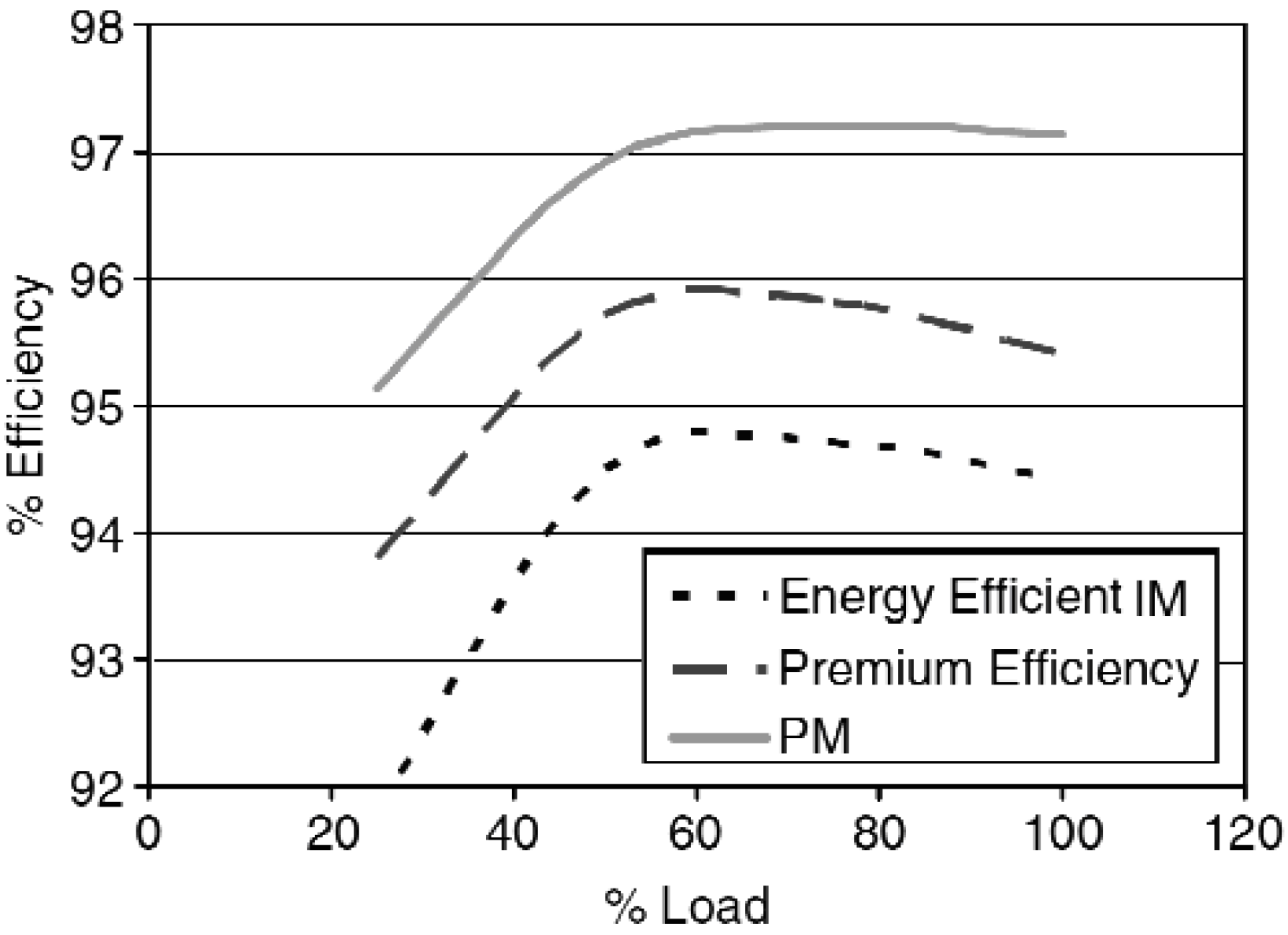
25]. It was reported that typically 50% of IM losses can be removed by keeping the stator the same and replacing the rotor with a permanent magnet (PM) rotor, which results in a brushless PM motor. These types of motors show opportunities to improve efficiency (
Figure 5) [
26] because of lack of magnetizing current (which is required in induction motors).
Figure 5 also illustrates that brushless PM motors can provide an opportunity to extend the efficiency to a level beyond that defined by National Electric Manufacturing Association (NEMA) Premium Efficiency. Furthermore, brushless PM motors can provide a very high power factor (approximately 0.95) that is noticeable specifically at light loads (which typically vary between 0.55–0.75 at light loads in IMs) [
26]. Note that the power factor indicates the effective utilization of the supply power and reduces the reactive power consumption. In addition, low speed operation of a pump results in some benefits in terms of reduced pump wear and maintenance costs. Although the brushless PM motors are more expensive than the IMs, the purchase price of an electric motor is a small part (approximately 3%–5%) of the total cost of operation (TCO). However, slight variations in their operating efficiency could dramatically affect the TCO through electricity costs (approximately 70% over their lifetime [
23]).
Figure 5.
The improved efficiency for PM motors and energy efficient IMs.
Figure 5.
The improved efficiency for PM motors and energy efficient IMs.
3.4. Variable Frequency Drives
The VFDs (or variable-speed controllers) can control motor speed by varying the effective voltage and frequency, which are obtained from a fixed voltage and fixed frequency three-phase mains supply. Brushless PM motors cannot operate without a VFD due to their structure. However, from a cost and complexity point of view, there is not much difference between the VFDs used in IMs and brushless PM motors for the same power ratings.
Because a VFD can operate the motor over a wide range of speeds, knowing the efficiency values of the VFD/motor combination at each operating point is important to accurately determine the operating point of a pump. Stockman
et al. [
27] demonstrated that the brushless PM motor/VFD has far better efficiency values compared to the IM/VFD.
It should be noted that in variable drive systems, additional losses are generated in the motor by the variable frequency drive.
4. Throttling Control Valve vs. Variable-Speed Drive−Case Studies
4.1. Modernization of Heating Stations from Timisoara, Romania to Reduce Environmental Impact and Energy Consumption
In Timisoara, Romania, the central heating system has equipment designed to meet the heat demand of the city. However, the equipment was produced in 1970s or 1990s, so their normal use does not meet current standards on energy efficiency or environmental protection. The European community requires that these rules be met; otherwise, the operation of the existing equipment will be stopped.
The central heating system is the sole heat source for a large number of buildings whose inhabitants do not have the financial power to buy individual heat sources, which is why the local and central authorities decided to keep the existing equipment operational. However, to maintain equipment as operational requires adapting them to new requirements. The company has developed a modernization plan for the most important sources of heat, and the municipality has access to the European funds for these works. The main works are focused on environmental protection, and some of them lead to increased efficiency.
Upgrading the central heating system in Timisoara for compliance to environmental standards on air emissions and increased efficiency in urban heat supply includes the following:
- (a)
Refurbishment of two hot water boilers located in the downtown district heating station. The first hot water boiler of 50 Gcal/h (58.15 MW) will be ready for burning fuel gas by installing a low NOx gas burner; the pressure part of the boiler will be fixed; the boiler automation will be replaced; and an online apparatus to measure the exhaust emissions of NOx, SO2, and powders will be installed. The second hot water boiler of 100 Gcal/h (116.3 MW) will be prepared for burning fuel gas and light oil in a low NOx gas burner; the pressure part of the boiler will be fixed; the boiler automation will be replaced, and an online apparatus to measure the exhaust emissions of NOx, SO2, and powders will be installed.
- (b)
Refurbishment of the three steam boilers on lignite of 100 t/h, 15 bar, and 250 °C (82 MW) for burning lignite with low NOx emissions and for improved efficiency. This refurbishment consists of providing secondary air to the upper part of the furnace reduce NOx emissions; mounting an injection system of urea at the end of furnace to reduce NOx emissions; using an afterburning grate to increase the boiler efficiency by reducing the mechanical unburned particles; supplementing the heat exchange surface of the steam super heater maintain a constant temperature of 250 °C overheating for efficient operation of the steam turbine throughout the entire load range; replacing the boiler automation to ensure efficiency throughout the load range; and implementing.
- (c)
A new flue gas desulfurization unit for the three steam boilers of 100 t/h to reduce SO2 emissions will be mounted. This will ensure gas desulfurization from the three steam boilers of 100 t/h steam, operating at rated load; flue gas desulfurization when the sulfur content of lignite peaks in normal quality conditions; flue gas desulfurization to a maximum SO2 content of 250 mg/Nm3 for 6% O2 in the flue gas composition.
- (d)
Modernization of four pumps from the downtown heating station (3 × 1300 m3/h and 1 × 1000 m3/h) and four pumps in the southern district heating station (1 × 1250 kW, 2 × 250 kW, 1 × 630 kW electric motor) by mounting new pumps and/or new motors and installing variable frequency converters.
4.2. Energy Efficiency of the Adjustment Methods
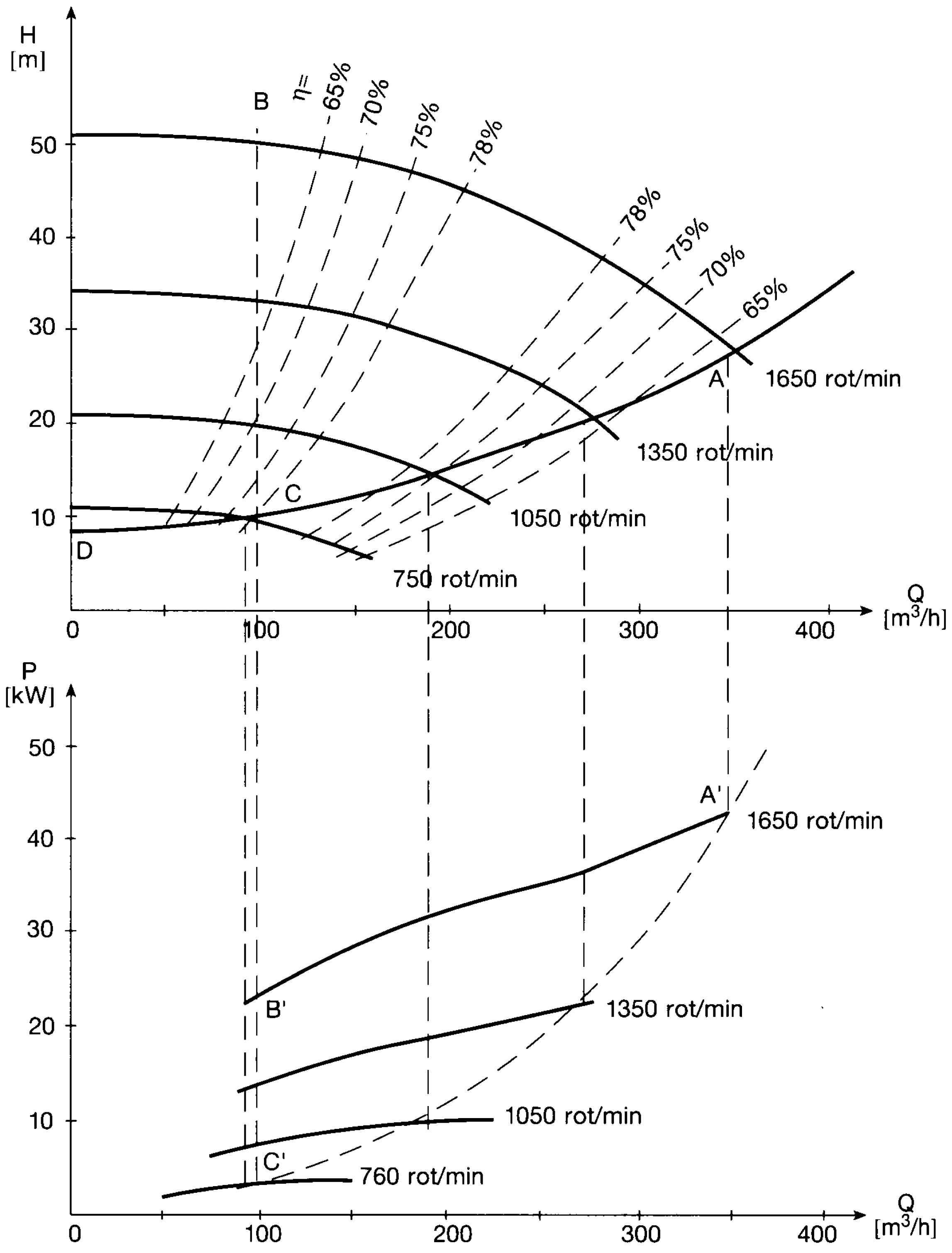
The heating stations from Timisoara are being modernized to increase their efficiency and to be less harmful to the environment. Before this modernization is accomplished, the operation of more pumps used in the heat supply period was analyzed. The energy efficiency of the above adjustment methods were analyzed based on pump operation for different rotational speeds (
Figure 6).
If the maximum discharge is 350 m3/h and the pump head is 28 m, the absorbed power results are 42.5 kW. If the water discharge is reduced to 100 m3/h using a throttling valve the pump head increases to 50 m and the absorbed power will be 23 kW at a constant rotational speed of 1650 rot/min. The operating curves are marked with A-B on the H-Q curve and with A’-B’ on the power diagram.
Figure 6.
Characteristic curves H-Q, P-Q and η-Q for a heating station pump.
Figure 6.
Characteristic curves H-Q, P-Q and η-Q for a heating station pump.
The correspondence with the power relations is presented by the dashed curve. Thus, comparing the absorbed power
P, using control valve and speed control is possible. Consequently, if the yearly distribution is known, the energy consumption
W, can be determined. The numerical results, based on the characteristic curves from
Figure 4, are summarized in
Table 1. From the results of the analysis, the yearly energy consumption decreases from 275,064 kWh to 124,173 kWh using rotational speed adjustment. The energy savings are approximately 151,000 kWh, which represents approximately 55%.
Table 1.
Energy consumption using control valve and speed control.
Table 1.
Energy consumption using control valve and speed control.
| Discharge Q [m3/h] | Distribution | Control Valve | Speed Control |
|---|
| % | Time τ [h] | Power P [kW] | Energy W [kWh] | Power P [kW] | Energy W [kWh] |
|---|
| 350 | 5 | 438 | 42.5 | 18,615 | 42.5 | 18,614 |
| 300 | 15 | 1314 | 38.5 | 50,589 | 29.0 | 38,106 |
| 250 | 20 | 1752 | 35.0 | 61,320 | 18.5 | 32,412 |
| 200 | 20 | 1752 | 31.5 | 55,188 | 10.0 | 17,520 |
| 150 | 20 | 1752 | 28.0 | 49,056 | 6.5 | 11,388 |
| 100 | 20 | 1752 | 23.0 | 40,296 | 3.5 | 6132 |
| Total | 100 | 8760 | - | 275,064 | - | 124,173 |
The use of VFDs reduces equipment and motor energy use. These reductions depend on the equipment type and the ratio to nominal rotational speed; average global losses could be considered less than 5% [
16]. Thus, reducing the energy savings obtained from VFDs with these losses results in a final energy savings of approximately 50%.
4.3. Assessment of Energy Savings with Variable-Speed Drives
The measured parameters of one pump were the hot water discharge and the water pressure. Measurements were performed every hour over eighteen days in April, a month with large variations in hot water discharge. In this period, the heat demand adjustment was made by varying the hot water discharge and keeping the hot water temperature constant. Knowing the water temperature, the required powers were calculated for every hour for two adjustment methods: throttling control valve and rotational speed variation with VFDs.
The pump characteristics were the following: type, TD 500-400-750; discharge, 3150 m3/h; and pump head, 70 m. The motor characteristics were the following: type, MIB-X 710Y; power, 800 kW; rated current, 94 A; voltage, 6000 V; rotational speed, 995 rpm; cosφ = 0.87; mass, 6000 kg.
Heat demand depends on the outdoor air temperature and is influenced by the return network temperature. The operational flow rate of the pump was of course lower than the nominal flow rate, for which the pump was built. To achieve the desired discharge, as provided in the chart control, the valve mounted on the pump outlet needed to be closed. Thus, by reducing the water discharge, the pump head becomes higher than that from the characteristic curves at the same flow rate. The power absorbed by the electric motor is also lower.
Figure 7 presents the characteristic curves
H =
f(
Q),
P =
f(
Q) and η =
f(
Q). For the case of throttling valve control, the absorbed power was computed using Equation (1) for each hour. The power absorbed by the electric motor with the frequency convertor is obtained from Equations (2) and (5):
where
P1 is the absorbed power of the FSP for the operating point
Q1 = 3150 m
3/h and
H1 = 70 m.
Figure 7.
Power variation of a heating station pump.
Figure 7.
Power variation of a heating station pump.
Table 2 provides the results obtained for comparative energy analysis of the two adjustment methods. The VFD’s method of speed control obtained energy savings of approximately 38% compared to the throttling control valve method.
Table 2.
Energy savings for pump speed control.
Table 2.
Energy savings for pump speed control.
| No. | Adjustment Method | Time τ [h] | Discharge Q [m3/h] | Pump Head H [m] | Power P [kW] | Energy W [kWh/day] | Specific Energy wp [kWh/m3] |
|---|
| 1 | Control valve | 6 | 2010 | 5.0 | 321.6 | 8531.2 | 0.167 |
| 4 | 1950 | 5.0 | 312.0 |
| 4 | 2200 | 5.5 | 387.2 |
| 4 | 2150 | 5.0 | 344.0 |
| 6 | 2300 | 5.5 | 404.8 |
| 2 | Speed control | 6 | 2010 | 4.6 | 183.6 | 5284.0 | 0.104 |
| 4 | 1950 | 4.6 | 167.6 |
| 4 | 2200 | 5.2 | 240.7 |
| 4 | 2150 | 4.6 | 224.7 |
| 6 | 2300 | 5.3 | 275.1 |
| Energy saving, ΔW | [MWh/year] | 1185.2 |
| [%] | 38.1 |
4.4. Economical Efficiency
The study has shown that the investment cost of auxiliary equipment for safety maintenance of variable-speed pumps represents approximately 10% of the total operation costs. Thus, 90% represents the energy consumption for the total operation period, which is approximately 15–20 years. At the same time, the energy savings obtained using variable-speed pumps will lead to a shorter recovery time of the investment costs. Therefore, an electricity tariff of 0.1 €/kWh and a supplementary investment cost of 6000 € for the case analyzed above (
Table 2) results in an investment recovery time of five years, on the basis of simple payback time economic criterion.
The electric energy used to pump hot water is approximately 35% of the total operation energy used in heating stations. The total power consumption of the heating station is approximately 10,000 kW, so the pump power consumption is 3500 kW. Energy savings from using variable-speed pumps compared with throttle control is 33%, which over the 4000 h heating season could save 4,620,000 kWh. This energy savings could reduce the financial burden of heating by approximately 500,000 € every year.
The diagram illustrated in
Figure 8 shows the possibility of establishing the energy savings using variable-speed pumps depending on the absorbed power, the
Q/
Qmax ratio and the yearly operation time. Thus, the case of a 15 kW motor power, an average operating discharge of 70% of the nominal value and an operating time of 5300 h/year (60%) would achieve an energy savings of 43,000 kWh.
Figure 8.
Yearly energy savings with variable-speed pumps.
Figure 8.
Yearly energy savings with variable-speed pumps.
5. Conclusions
Flow rate adjustment with variable-speed pumps is an advantageous method of water pumping in district heating stations, assuring the correlation between the heat demand and water discharge and so obtaining important energy savings that can reach up to 50%.
The water pressure is met continuously at the required values by pump speed control, obtaining an important reduction of water losses in the system. Additionally, the high-pressure values that can lead to equipment operation defects are avoided.
Using frequency converters, the rotational speed of the electric driven pumps can be increased, obtaining higher values than the nominal ones, thus increasing the pumping capacity as well. The required power at the motor shaft decreases with the cube of pump speed, which could reduce the life cycle costs of the motor-pump assembly.
For varying the pump speed, the variable frequency drives are the best solution because these are connected between the electric motor and the energy source and set for the specific requirements. Although induction motors are commonly used in heating stations with FSPs, brushless PM motors offer significantly higher efficiency and higher power factors, specifically at low speeds and light loads. In addition, motor installation issues play a significant role in the total efficiency of the system.


