Energy Return on Energy Invested (EROI) for the Electrical Heating of Methane Hydrate Reservoirs

Abstract
:1. Introduction
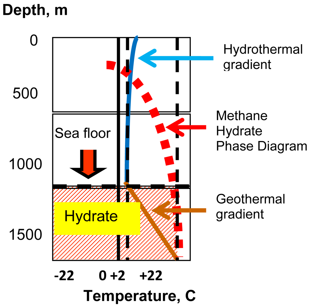
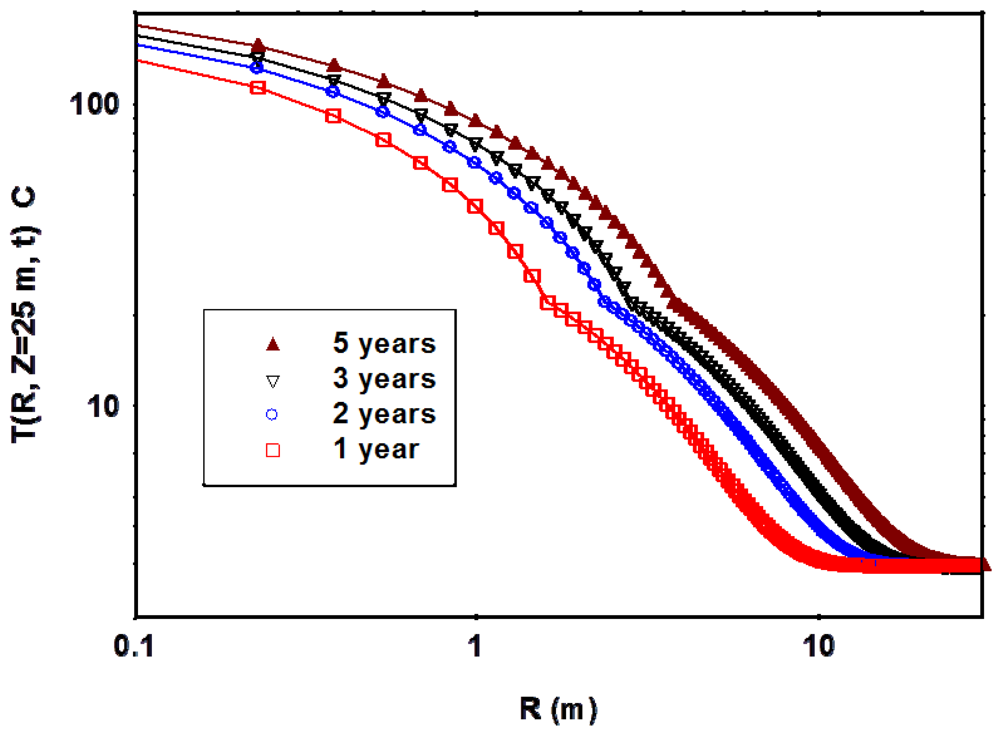
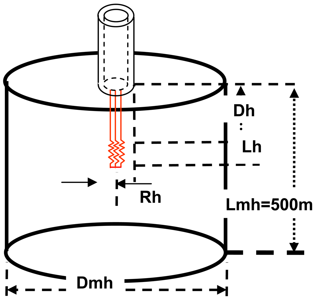
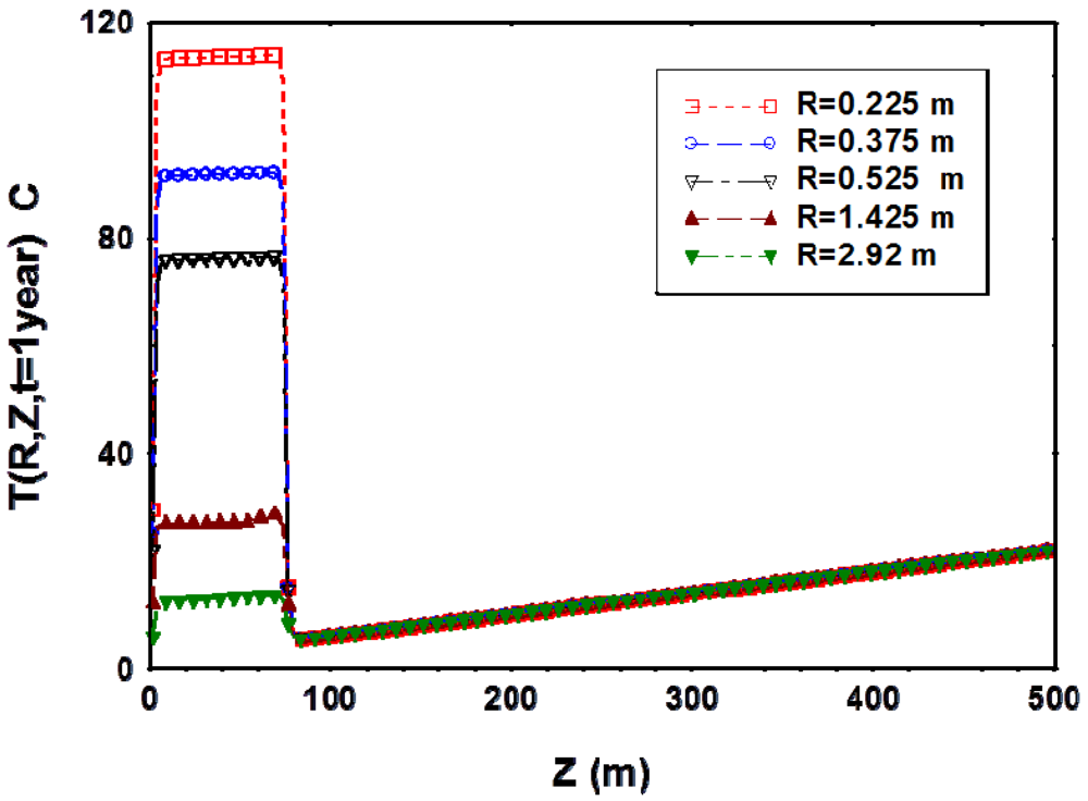
2. Temperature Distribution in the MH Deposits
- MH: latent heat = 438540 joules/kg
- MH specific heat = 2108 joules/(kg K)
- MH density = 913 kg/(m3)
- MH thermal conductivity = 0.5 watts/(m.K)
- Water specific heat = 4187 joules/(kg.K)
- Water density = 1000 kg/(m3)
- Water thermal conductivity = 0.58 watts/(m.K)
- Copper specific heat = 385 joules/(kg.K)
- Copper density = 8920 kg/(m3)
- Copper thermal conductivity = 401 watts/(m.K)
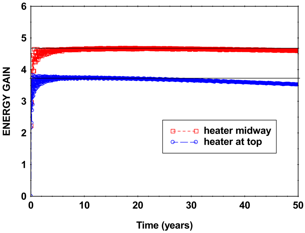
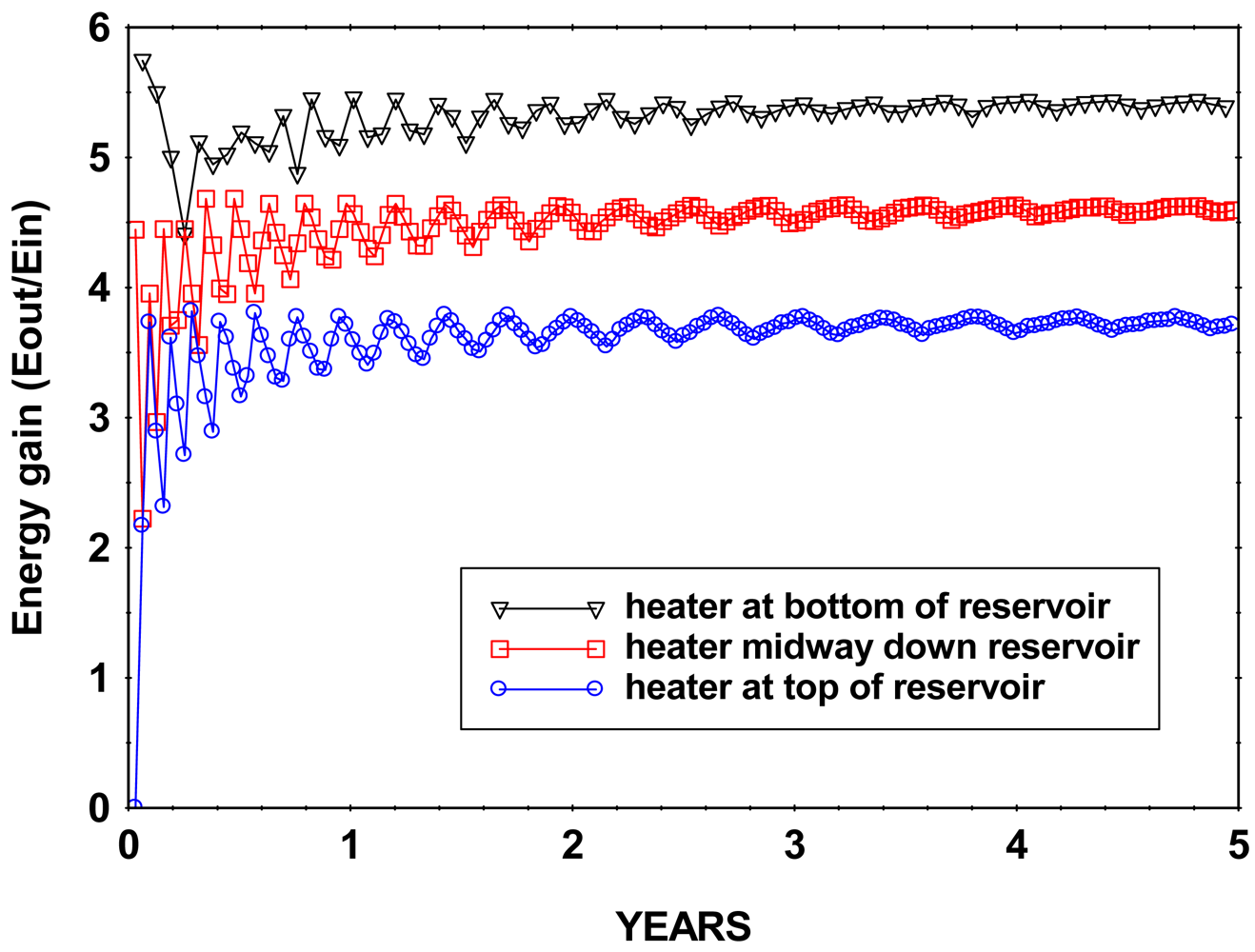
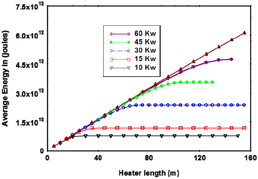
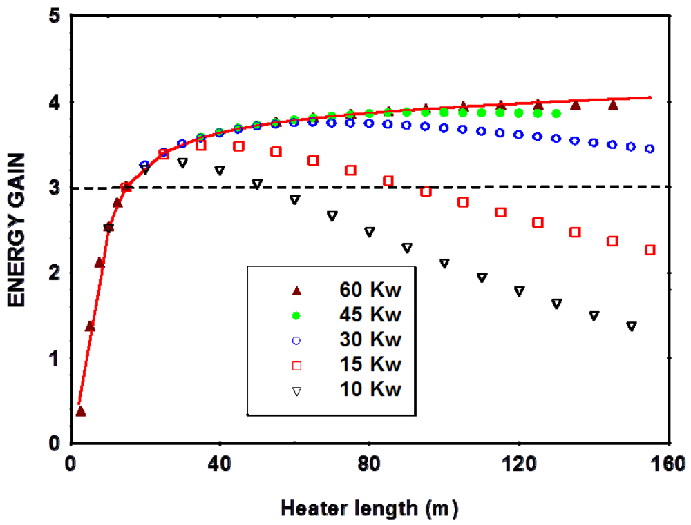
3. Energy Efficiencies at Different Input Power Levels
- One cubic meter of methane hydrate yields 160–170 cubic meters of methane at standard temperature and pressure (STP 0 °C and 1 atm)
- Measurements of the heat of combustion of methane [13] yield a value of 8.906 × 10⁵ joules/mol corresponding to 3.868 × 10⁷ joules/m3 of methane. This value closely agrees with an energy content of 1000 BTU per cubic foot, well in the range of the 500–1000 BTU per cubic foot reported in the literature for natural gas [14].
- Thus 1 cubic meter of methane hydrate producing 160 m3 of methane gas yields an equivalent energy of 6.1 × 10⁹ joules.
4. Conclusions


References and Notes
- Makogon, Y.F. Hydrates of Natural Gas; PennWell Publishing Company: Tulsa, OK, USA, 1981. [Google Scholar]
- Sloan, E.D. Clathrate Hydrates of Natural Gases; Marcel Dekker Inc.: New York, NY, USA, 1998. [Google Scholar]
- Carroll, J. Natural gas Hydrates, 2nd ed.; Elsevier: Oxford, UK, 2009. [Google Scholar]
- Kvenvolden, K.A. Gas hydrates as a potential energy resource: A review of their methane content. In The Future of Energy Gases; USGS Professional Paper 1570; USGS: Reston, VA, USA, 1993; pp. 555–561. [Google Scholar]
- Demirbas, A. Biohydrogen: For Future Engine Fuel Demands; Springer-Verlag: London, UK, 2009. [Google Scholar]
- Arata, N.; Sukizaka, S.; Awashima, Y. Overview of the R&D Program For An Environmental Impact Assessment Of Hydrate Exploitation in Japan. Proceedings of OCEANS'08 MTS/IEEE conference, Quebec, Canada, September 2008. IEEE Press.
- Callarotti, R.C. Electromagnetic heating of oil, in SPE Handbook of Petroleum Engineering Vol. 6; Chapter 12; Lake, L., Ed.; Society of Petroleum Engineers: Houston, TX, USA, 2007; Volume 6, pp. 567–609. [Google Scholar]
- Callarotti, R.C. Methane Hydrates As An Energy Source. Proceedings of the International Annual Conference Interdisciplinary Approaches to Sustainability, CIEMADEeS Second International Annual Conference, Gurabo, Puerto Rico, 3–5 November 2006; retrieved from http://ciemades.org/gurabo06_eng.html.
- Callarotti, R.C. Energy Efficiency In The Electrical heating Of Methane Hydrate Reservoirs. SPE paper 137585. Proceedings of the Canadian Unconventional Resources and International Petroleum Conference, CURIPC 10, Calgary, Alberta, Canada, 19–21 October 2010; Society of Petroleum Engineers: Houston, TX, USA.
- Chun-Pyo, H. Computer Modeling of Heat and Fluid Flow in Materials Processing; Institute of physics printing: Bristol, UK, 2004. [Google Scholar]
- Gupta, A.; Lachance, J.; Sloan, E.D.; Koh, C.A. Measurements of methane hydrate heat of dissociation using high pressure differential scanning calorimetry. Chem. Eng. Sci. 2008, 63, 5848–5853. [Google Scholar]
- Waite, S.F.; Stern, L.A.; Kirby, S.H.; Winters, W.J.; Mason, D.H. Simultaneous determination of thermal conductivity, thermal diffusivity and specific heat in sI methane hydrate. Geophys. J. Int. 2007, 169, 767–774. [Google Scholar]
- Dale, A.; Lythall, C.; Aucott, J.; Sayer, C. High precision calorimetry to determine the enthalpy of combustion of methane. Thermochim. Acta 2002, 382, 47–54. [Google Scholar]
- Speight, J.G. Synthetic Fuel Handbook; McGraw Hill: New York, NY, USA, 2008. [Google Scholar]
- Yamakawa, T.; Ono, S.; Iwamoto, A.; Sugai, Y.; Sasaki, K. A Gas Production System From Methane Hydrate Layers By Hot Water Injection And BHP Control With Radial Horizontal Wells. SPE paper 137801. Proceedings of the Canadian Unconventional Resources and International Petroleum Conference, CURIPC 10, Calgary, Alberta, Canada, 19–21 October 2010; Society of Petroleum Engineers: Houston, TX, USA.
© 2011 by the authors; licensee MDPI, Basel, Switzerland. This article is an open access article distributed under the terms and conditions of the Creative Commons Attribution license (http://creativecommons.org/licenses/by/3.0/).
Share and Cite
Callarotti, R.C. Energy Return on Energy Invested (EROI) for the Electrical Heating of Methane Hydrate Reservoirs. Sustainability 2011, 3, 2105-2114. https://doi.org/10.3390/su3112105
Callarotti RC. Energy Return on Energy Invested (EROI) for the Electrical Heating of Methane Hydrate Reservoirs. Sustainability. 2011; 3(11):2105-2114. https://doi.org/10.3390/su3112105
Chicago/Turabian StyleCallarotti, Roberto Cesare. 2011. "Energy Return on Energy Invested (EROI) for the Electrical Heating of Methane Hydrate Reservoirs" Sustainability 3, no. 11: 2105-2114. https://doi.org/10.3390/su3112105