
Dynamic Response of Steel–Timber Composite Beams with Varying Screw Spacing
by
 , , , and
Małgorzata Abramowicz
1,*,
Marcin Chybiński
2,
Łukasz Polus
2,*,
Piotr Szewczyk
1 and
Tomasz Wróblewski
1 1
Faculty of Civil and Environmental Engineering, West Pomeranian University of Technology in Szczecin, Al. Piastów 17, 70-310 Szczecin, Poland
2
Institute of Building Engineering, Faculty of Civil and Transport Engineering, Poznan University of Technology, Piotrowo 5 Street, 60-965 Poznan, Poland
*
Authors to whom correspondence should be addressed.
Sustainability 2024, 16(9), 3654; https://doi.org/10.3390/su16093654
Submission received: 3 April 2024
/
Revised: 17 April 2024
/
Accepted: 23 April 2024
/
Published: 26 April 2024
Abstract
:Steel–timber composite beams are a relatively new type of composite structure. They have many important advantages, owing to which they may be considered a sustainable solution. Their connectors may be demountable, which makes it possible to separate steel girders from LVL panels at the end of their service life. After disassembly, the structural elements can be recycled. One of their advantages is that they are lighter than steel–concrete composite beams. However, this may result in the poor performance of floors with steel–timber composite elements subjected to dynamic loadings. For this reason, the dynamic characteristics of floors should be investigated to verify the serviceability limit state of human-induced vibrations. In this study, the dynamic response of the three steel–timber composite beams with varying screw spacing was captured and used to validate their numerical models. The frequencies obtained from the numerical analyses correspond to the experimental results. A very high agreement between the vibration mode shapes was obtained because the MAC index values were close to 1. The validated numerical model of a single steel–timber beam may be used in future studies to create a complex numerical model of a steel–timber composite floor.
1. Introduction
1.1. Steel–Timber Composite Beams as Sustainable Structural Elements
Steel–timber composite beams may be considered as sustainable solutions for civil engineering thanks to some important factors. First of all, the overall effectiveness of composite beams is higher than the sum effectiveness of their single parts. It is possible to reduce cross-section heights thanks to composite action [1]. For this reason, the combination of steel and timber in composite beams is a method for reducing the use of resources [2]. Composite and hybrid structures offer solutions that satisfy the relevant performance criteria while keeping the trade-off between financial cost and environmental impact [3]. Sustainable construction is open to modern solutions, which minimize the waste in landfills [4]. To satisfy this requirement, new civil engineering structures should be easily deconstructed at the end of the structure service life [5]. Steel–timber composite beams with demountable connections can be used in frame structures, and frame elements can be recycled [6]. Furthermore, some structural elements can be reused or repurposed when well-considered building design and deconstruction are applied. The use of steel–timber composite beams can reduce the embodied energy [7]. Chiniforush et al. compared the life cycle energy implications of adopting steel–timber composite floors in steel and concrete structures [7]. The building with steel–timber composite floors and cross laminated timber shear walls provided the lowest embodied energy, highlighting the energy-saving benefits of using steel–timber composite structures. Steel–timber composite beams also have several other important performance characteristics that make them sustainable, e.g., a shorter construction time than steel–concrete composite beams [8]. They may improve the insulation performance of a building [9]. Slabs of steel–timber composite beams can be made of sustainable engineering wood products, such as laminated veneer lumber (LVL) and cross-laminated timber (CLT). Thanks to these engineered wood products, timber is gaining popularity as a construction material [10]. The size of the engineered wood products is not limited by the size of wood [11,12]. LVL is produced from trees of relatively small diameters [13]. The wood used in the LVL manufacturing process may come from sustainable sources, such as certified or controlled forests, where felled trees are replaced with seedlings [14]. In the manufacturing process, knots are reduced to the individual veneer layer and distributed evenly [15]. For this reason, LVL has a higher strength and rigidity than sawn lumber and is more homogeneous. It also has a high level of prefabrication [16]. The environmental performance of LVL was compared to steel and concrete in a life cycle assessment (LCA) [17]. The embedded energy of the LVL structural element made from thinned logs was lower than that of a beam made of concrete and only marginally lower than that of a steel beam. However, the LVL beam made from mature hardwood logs had a much higher embedded energy than the beams made of LVL from thinned logs or steel. LVL structural elements may be strengthened using carbon fibre-reinforced polymer sheets bonded to the upper and lower surfaces [18]. LVL is made from softwood veneers oriented in one direction or with some veneers glued crosswise [19], whereas CLT is mass timber made of dimension lumber laminated orthogonally [20]. CLT has good in-plane dimensional stability and can be prefabricated, shortening the construction time and reducing waste [21,22]. CLT wall panels have a high in-plane stiffness and strength.
The steel girders used in steel–timber composite beams may also contribute to sustainable construction, provided that some improvements and innovations are applied [23]. Advanced processes and product technologies should be used to reduce emissions. The efficient and effective management of raw materials, energy, water, and by-products may be beneficial for the mitigation of CO2 emissions from steelmaking processes [24]. Prefabrication and factory-based work may facilitate waste reduction. Steel girders may be reused or recycled. They can be made of hot-rolled [25,26,27] or cold-formed elements [28]. Cold-formed steel beams have high strength-to-weight ratios [29]. To increase the durability of steel–timber composite beams, it is necessary to protect the carbon steel girders from corrosion. It is also possible to use stainless steel. The next option is to use aluminium alloy girders [30]. Stainless steel and aluminium alloys are expensive, but they have lower maintenance costs than carbon steel. Furthermore, stainless steel shows greater thermal expansion, strength retention, and stiffness at high temperatures than carbon steel [31].
1.2. Dynamic Tests of Steel–Timber Composite Beams
Floors with steel–timber composite elements are lighter and have lower inherent damping than floors made of steel–concrete composite elements [32]. The serviceability criterion becomes increasingly more important as a result of the use of longer spans [33,34]. For this reason, the vibration performance of steel–timber composite floors should be investigated. Their dynamic characteristics should be within the range of human comfort [35]. Furthermore, structural elements should be protected against the adverse effects of vibrations [36]. The results of dynamic tests may be used in damage detection processes [37]. Chiniforush et al. conducted extensive modal tests and numerical analyses of steel–timber composite structural elements [32]. The acceleration response, damping ratios, vibration mode shapes, and natural frequencies of six steel–timber composite beams were extracted. The beams differed in connector types (coach screws, dog screws, coach screws and grout packets, post-tensioned bolts), CLT panel orientations (parallel and perpendicular grain direction), and the presence of screws in the CLT panel joints. Numerical models of the steel–timber composite beams were developed and validated using a genetic algorithm. The validated numerical models were used to evaluate the performance of steel–timber composite floors exposed to human-induced vibrations [38]. It was demonstrated that floors with steel–timber composite elements can be used in offices, and residential, industrial, and sport buildings. However, only the dynamic responses of steel–timber composite beams with CLT panels and 16 mm connectors with 250 mm and 300 mm spacing were investigated.
In this paper, three steel–timber composite beams with LVL slabs and varying screw spacing were analysed. Steel–timber composite beams may be used as the load-bearing structural elements of floors [39]. The purpose of this research work was to capture the dynamic response of the steel–timber composite beams and to validate their numerical models. The validated numerical model of a single steel–timber composite beam may be used in future studies to create a complex numerical model of a steel–timber composite floor. Such a model will allow for the study of floor dynamic properties and for the verification of the serviceability limit state of human-induced vibrations. Furthermore, the results of this study may be used in structural health monitoring processes.
2. Materials and Methods
2.1. The LVL Panels
The slabs (75 × 300 × 3000 mm) were made of LVL, with all veneers glued lengthwise [40]. The basic dynamic characteristics and the material parameters of the LVL slab were obtained in a previous study [41]. The natural frequencies of the slab from the experiment were used to identify the material parameters (Table 1). The developed and validated numerical model of the LVL slab from the previous investigation [41] was used in this study to develop a numerical model of the steel–timber composite beam.
2.2. The Steel Girders
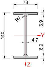
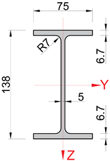
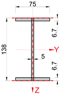
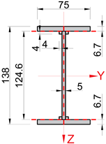
The 3 m steel girders (IPE 140) were made of S355J2-grade steel. Table 2 presents the chemical composition of the steel.
Based on the manufacturer’s inspection certificate [42], the yield strength of the steel was 472 MPa, the tensile strength was 562 MPa, and the elongation after fracture (A5) was 31.5%. The cross-section properties from the tables [43] and the measured dimensions are presented in Table 3. The disparity between the catalogue dimensions and the measured dimensions was within the tolerances for shape and dimensions specified by the EN 10034:1996 standard [44]. In the numerical simulations, the measured dimensions from the experiments were used.
2.3. The Experimental Test of the Steel Girder
A steel girder suspended on 4 mm steel cables was tested as a free element on a steel stand (Figure 1 and Figure 2). The suspension points of the girder were selected to correspond to the theoretical nodal points of the first flexural mode of vibration of the steel girder. The same stand, consisting of cantilever frames and angle bracing, was also used in the previous studies to determine the dynamic parameters of LVL slabs, steel–concrete composite beams, and steel girders [41,45]. The impact of stand deformability on the results was considered insignificant when a free-free scheme was used [46]. In the laboratory test, the steel girder was excited into vibration using a 0.32 kg impact hammer (Modally Tuned, ICP, 086D05, PCB Piezotronics, Depew, NY, USA). It was equipped with a white plastic insert tip (medium-hard, 084B04) (Figure 3). The vibration acceleration was measured, and the frequency of the natural vibration was determined. Nine triaxial accelerometers (PCB 356A01, PCB Piezotronics, Depew, NY, USA) were used. They were fixed to the steel girder using the manufacturer’s accelerometer wax. The excitation was generated at three points on the steel girder, labelled in Figure 2 as follows: 19 − z vertical impact at the beginning of the longitudinal axis of the steel girder, 20 + x horizontal impact on the steel girder face, and 21 + y horizontal impact on the steel girder edge. Thanks to the various excitation points, different vibration modes of the steel girder were obtained. Point 19 − z was applied to study the vertical flexural mode. Point 20 + x was applied to investigate the axial mode of vibration. Horizontal flexural and torsional modes were obtained thanks to the use of the 21 + y point. Eighteen measurement points were evenly distributed on a mesh (Figure 2). The tests were conducted in two stages. In the first stage, nine accelerometers were placed on the top flange. In the second stage, they were placed on the bottom flange. For each excitation point, the steel girder was hit five times. The LMS SCADAS III (Siemens, Plano, TX, USA) data acquisition system was used to record the acceleration responses. The Impact Testing module (LMS Test Lab package, Siemens, Plano, TX, USA) was also used in the dynamic tests.
2.4. The Laboratory Tests of the Steel–Timber Composite Beams
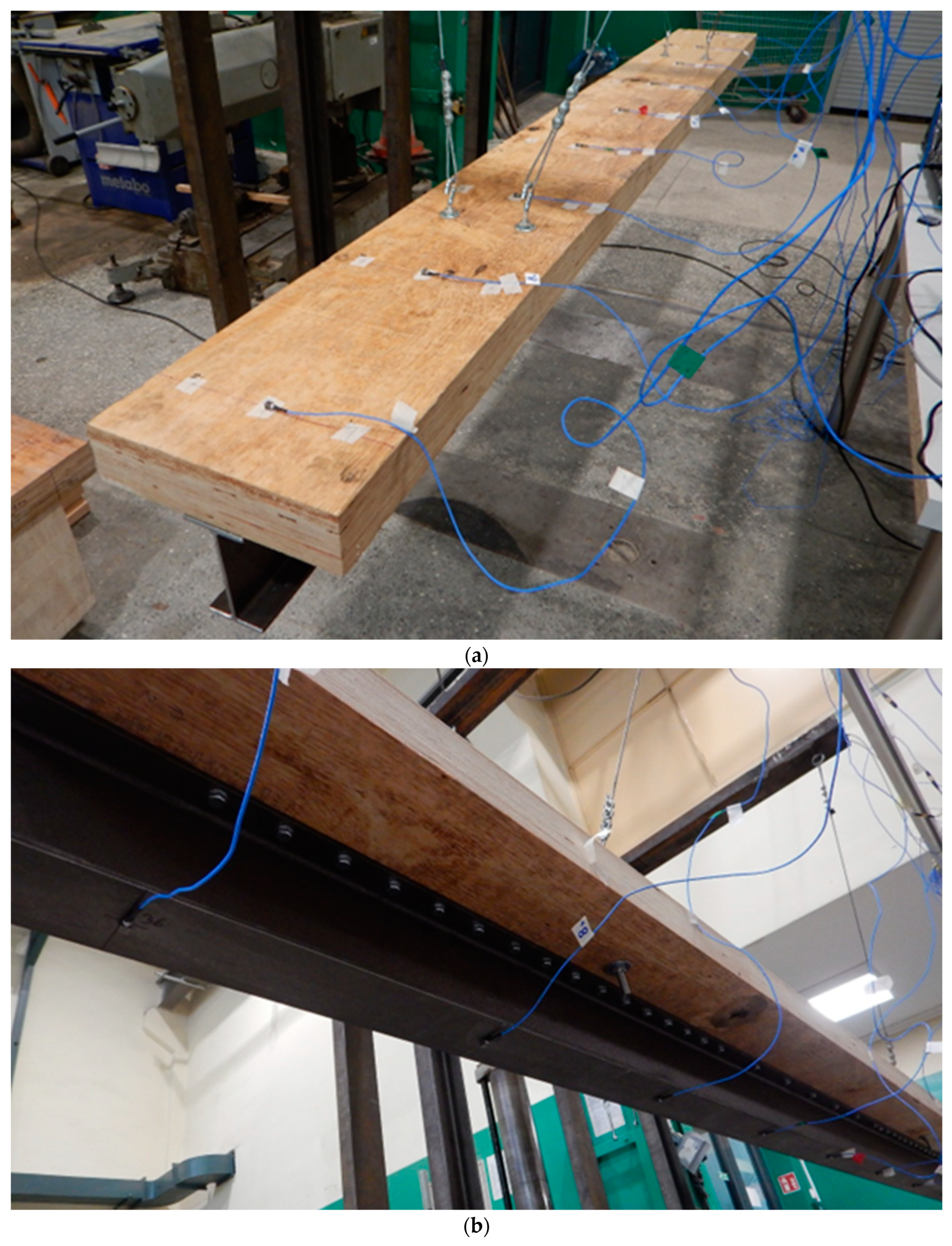
Three steel–timber composite beams with different screw spacing were tested. Each composite beam consisted of a steel girder, an LVL slab, and hexagon head wood screws. The dimensions of the steel–timber composite beams were the same, and the beams only differed in the spacing and number of shear connectors (Figure 4). The transverse screw spacing was identical, i.e., 50 mm. However, the longitudinal spacing was 30 mm, 60 mm, and 90 mm, depending on the steel–timber composite beam. Based on the screw spacing, the tested steel–timber composite beams were labelled as S30, S60, and S90. Moreover, 8 mm holes were drilled through the steel girder top flanges, and 5 mm × 55 mm pre-drilled holes were used in the LVL slabs. A torque wrench (Sandvik Belzer, IZO-I-100, 10–100 N·m, Sandvik, Portlaoise, Ireland) was used to install the screws with a similar torque moment (28.0 N·m). Each steel–timber composite beam was suspended from the stand frame with 4 mm steel cables (Figure 5). The suspension points of the steel–timber composite beams corresponded to the theoretical nodal points of their first flexural vibration mode. During the experimental tests, an experimental modal analysis [47] and an impact hammer test were used. The test involved exciting the steel–timber composite beams into vibration using a 0.32 kg modal hammer. The hammer (Modally Tuned, ICP, 086D05, PCB Piezotronics, Depew, NY, USA) was equipped with a head for measuring the force and time of impact (Figure 3). The system response (steel–timber beam vibration acceleration) was measured using nine triaxial accelerometers (PCB 356A01, PCB Piezotronics, Depew, NY, USA). Based on the performed measurements, natural frequencies and modes were estimated. Excitation was generated at four points on the steel–timber composite beam, marked in Figure 6 as follows: 37 − z vertical impact at the beginning of the longitudinal axis of the steel–timber composite beam, 39 − z vertical impact on the edge of the LVL slab, 38 + x horizontal impact on the face of the LVL slab, and 39 + y horizontal impact on the edge of the LVL slab. Point 37 − z was applied to investigate the vertical flexural mode, and point 39 − z was applied to investigate the vertical flexural and torsional modes. Point 38 + x was used to obtain the axial mode of vibration. Point 39 + y was applied to investigate the horizontal flexural mode. A total of 36 measurement points were evenly distributed on a mesh (Figure 6).
The purpose of this research was not only to determine the natural frequencies but also the mode shapes of vibration of the steel–timber composite beams. The higher number of measurement points in the mesh resulted in more accurate results in terms of mode shapes of vibration, especially at higher frequencies. The tests were conducted in four stages. Nine accelerometers were used at different points in one line at every stage of the test (Figure 7). For each excitation point, the steel–timber composite beam was hit five times. The Impact Testing module (LMS Test Lab package, Siemens, Plano, TX, USA) and the LMS SCADAS III data acquisition system (Siemens, Plano, TX, USA) were used in the dynamic tests.
2.5. The Numerical Models of the Steel Girder
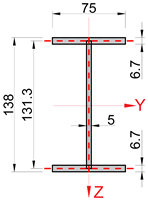
Numerical models of the steel girder were developed in Abaqus/CAE. The steel density, Young’s modulus, and Poisson’s ratio were assumed to be 7850 kg/m3, 207.8 GPa, and 0.3, respectively. The girder was modelled using quadrilateral S4R shell elements with reduced integration. The same elements were also used to model steel elements in previous works [48]. The maximum mesh size was 15 mm. Due to the fact that shell elements were used, the flanges and the web were represented by surfaces (Table 4). The red dashed lines represent the axes of the shell elements. The cross-sections of models A, B, and C had identical dimensions. However, they exhibited different moments of inertia and cross-sectional areas because the web overlapped the flanges in models A and B.
In the case of the flanges, the surface coincided with the axe of the flange (model A), the external edge of the flange (model B), and the internal edge of the flange (model C). However, none of these solutions took into account the flange-to-web fillet radii, and, as a result, the torsional stiffness was inadequate. In the case of models A–C, one could increase the flange thickness to obtain similar moments of inertia. The solution with thicker flanges was used by Pełka-Sawenko et al. [45]. In this paper, a different solution was used to take into account the flange-to-web fillet radii. In model D, additional mass was added in the flange-to-web connections. The dimensions of the additional mass were identified through an optimization process in which the error between the experimental frequencies and the frequencies from the numerical model was minimized. The moments of inertia and the cross-sectional areas of models A–D are presented in Table 4. The values may be compared with the parameters based on the measured dimensions in Table 3. Section 3.1 presents the results obtained for models A–D and discusses the choice of the steel girder model adopted for the analysis of the steel–timber composite beam.
2.6. The Numerical Models of the Steel–Timber Composite Beams
The numerical models of the steel–timber composite beams were created using the numerical model of the LVL slab developed in the previous study [41] and the numerical model of the steel girder (model D) presented in Section 2.5. The LVL slab was modelled using C3D8I solid first-order elements, the girder was modelled using S4R shell elements with reduced integration, and the shear connectors were modelled using B31 line elements. The maximum mesh size was 15 mm. Four numerical models were created, differing in the way the slab was connected to the girder or in the number of connectors. A view of the model is presented in Figure 8a. The connection modelling was the key parameter. In the first model, the tie function was used. Due to this fact, the LVL slab and the steel girder could not move relative to each other on the entire contact surface between them (Figure 8b). In the remaining models, the flexibility of the connections was taken into account using discreet connectors. The spacing between the connectors was identical to the spacing in the experimental models, i.e., 30, 60, and 90 mm in the shear span (Figure 8c). Each connector was assigned linear and angular displacement properties. The Cartesian type was assumed for translation, and the Aling type was used for rotations. In two directions parallel to the connection surface, the stiffness of one connector (4830 N/mm) was based on the model presented in [49]. The possibility of the displacement perpendicular to the connection surface was blocked. No rotation was allowed around any of the axes. For this reason, the connectors connected the LVL slab to the steel girder, allowing only for relative displacement in two directions parallel to the connection surface. A similar model of the connector was used by Romero et al. [50], but it only allowed for relative displacement along the longitudinal axis of the composite beam. In the numerical models with the discreet connectors, hard contact was used in the direction perpendicular to the connection surface, and friction (coefficient of friction = 0.3, based on [51,52]) was used in the direction parallel to the connection surface. What is more, in the finite element models of the steel–timber composite beams with discrete connectors, steel beam elements (shear connectors) were added and embedded in the LVL slabs to increase the mass of the composite beams (Figure 8d). The cross-section of the beam element was circular, with a 4 mm radius, and the length of the beam element was 60 mm (the embedded length of the screw in the LVL slab). However, in the numerical models, these steel beam elements were not used to join the steel girder and the LVL slab. They were only used to take into account the share of the screws in the composite beam mass. The connection between the steel girder and the LVL slab was created thanks to the discreet connectors.
3. Results
3.1. The Results of the Experimental and Numerical Analyses of the Steel Girder
The natural frequencies of the steel girder are summarized in Table 5. The results were divided into four groups: hf—horizontal vibrations, vf—vertical vibrations, t—torsional vibrations, and a—axial vibrations. The second column of Table 5 presents the results from the experimental tests described in Section 2.3. The following columns present the results obtained in the numerical simulations of models A–D. The relative error was calculated using Equation (1).
Furthermore, index S was used to evaluate the consistency between the numerical model and the experiment. The index was the sum of the squares of relative errors of the first m horizontal vibration frequencies, n vertical vibration frequencies, o torsional vibration frequencies, and one axial vibration frequency. The specific values of m, n, and o were determined based on the experimental test results. The most representative modes of vibration obtained during the dynamic tests were selected. Different types of modes of vibration (horizontal, torsional, vertical, and axial) were selected to find an accurate numerical model and to adjust it in various directions. The lower the value of index S, the greater the consistency of the numerical model and the experiment. A similar index was used in previous tests by Abramowicz et al. [46] to estimate the consistency of the vibration frequency of steel–concrete composite beams and their models.
All models demonstrated satisfactory accuracy in their results in terms of both flexural and axial vibrations. A small difference was visible for torsional vibrations, for which model D better reflected the behaviour of the steel girder than models A–C. For this reason, model D was used in further analyses of the steel–timber composite beams. Figure 9 shows the vibration modes obtained experimentally and numerically (for model D).
In addition to the comparison presented in Figure 9 and Table 5, the mode shapes of vibration were compared using the modal assurance criterion (MAC) (Figure 10 and Figure 11). The MAC was calculated as follows [41,53,54,55,56]:
where QA and QB represent the mode shape vectors that were being compared.
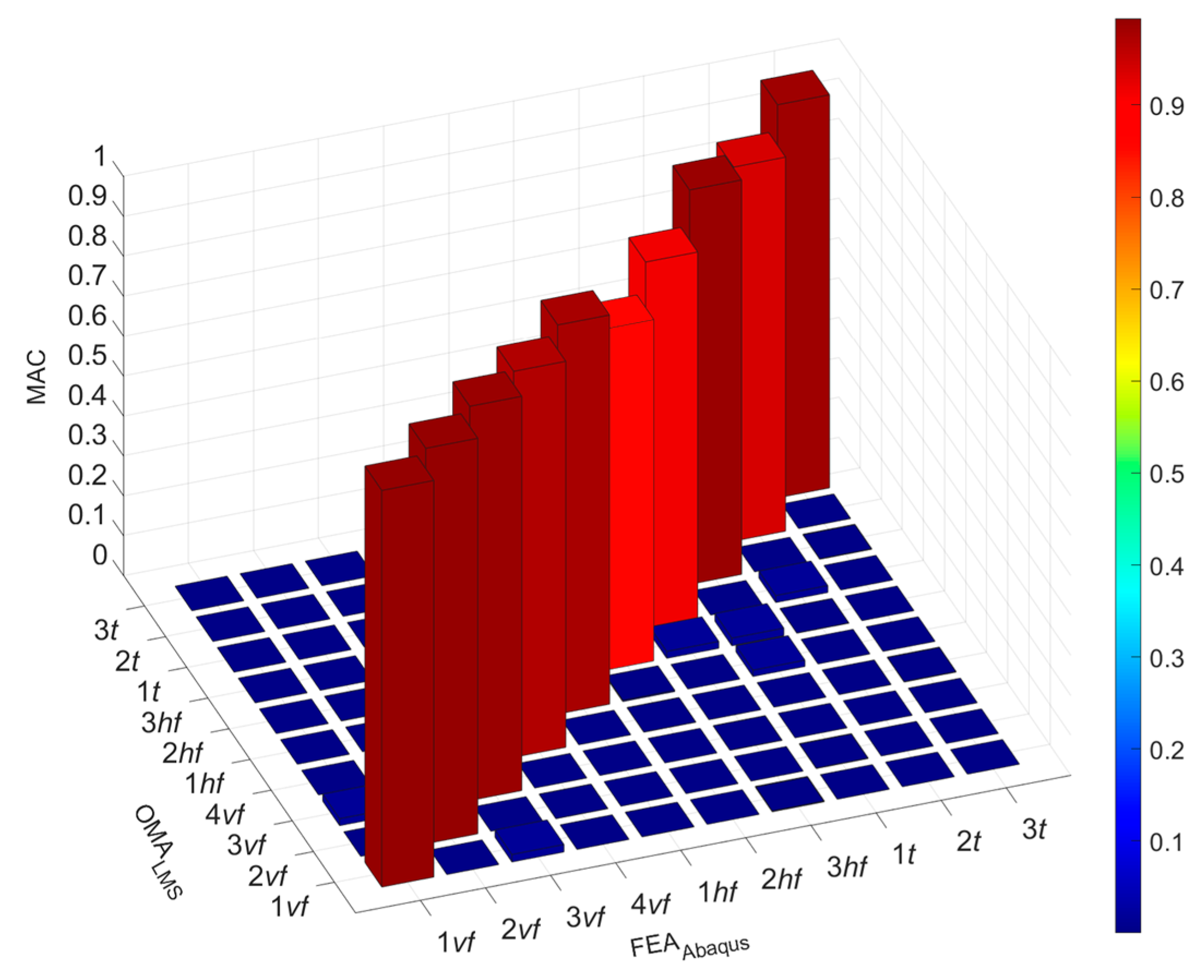
An analysis was performed for the results from the experiment and numerical simulations of model D. The MAC index values were close to 1. For this reason, the experimental and numerical results were in high agreement.
3.2. The Results of the Experimental and Numerical Analyses of the Composite Beams
The following modes of vibration of the steel–timber composite beams were analysed: three vertical vibrations (vf), two horizontal vibrations (hf), four torsional vibrations (t), and one axial vibration (a). The frequencies obtained in the experimental tests were compared with the results from the numerical analyses. Table 6 shows the results of the laboratory tests of the S30, S60, and S90 steel–timber composite beams and the numerical analysis of the steel–timber composite beam with the rigid connection between the LVL slab and the steel girder (Figure 8b). The numerical model based on the connection modelled using the tie function captured the response of each steel–timber composite beam fairly well. However, the frequencies obtained from the numerical model consistently exceeded those obtained in the laboratory tests. This outcome stemmed from assuming infinite stiffness in the connection between the steel girder and the LVL slab.
A comparison between the frequencies obtained in the numerical analyses of the models with discreet connectors (Figure 8c) and those from the laboratory tests is presented in Table 7. In these models, the same number of connectors was used as in the laboratory tests. The models took into account the flexibility of the connections. For this reason, the relative errors for the composite beams with the discreet connectors were lower than the relative error for the composite beam with the rigid connection. Figure 12 shows the vibration modes obtained experimentally and numerically for the S90 steel–timber composite beam.
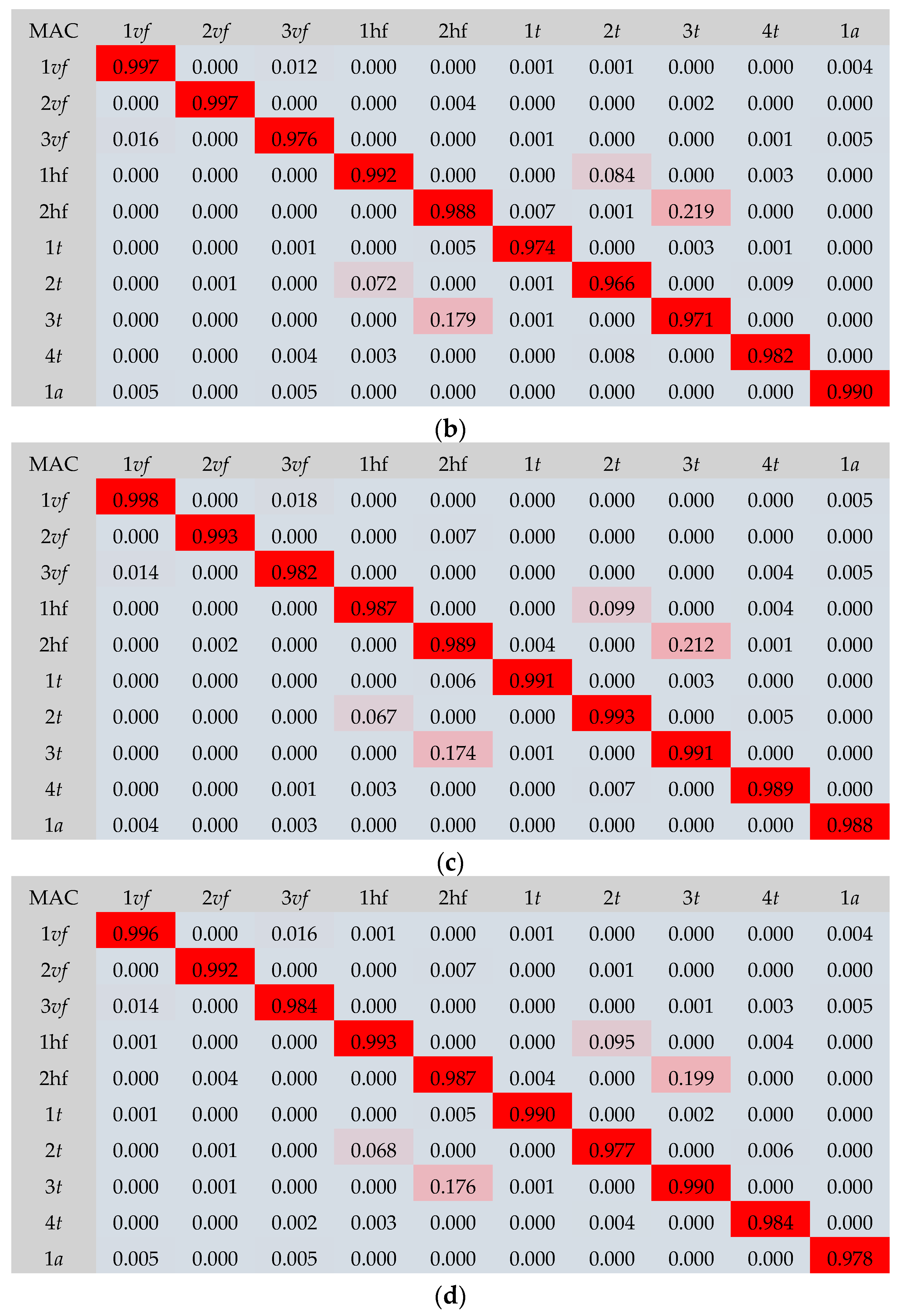
In addition to the comparison presented in Figure 12 and Table 6 and Table 7, a comparison using the modal assurance criterion (MAC) was conducted (Figure 13 and Figure 14). In the numerical analyses, the same mesh of measurement points as in the experimental tests was used. Both the results from the numerical analyses and the experimental tests were normalized to 1 and compared after the normalization process. A high agreement between the experimental and numerical results was obtained because the MAC index reached values close to 1.
4. Discussion
In this paper, models of steel–timber composite beams with varying screw spacing were developed. Before the steel–timber composite beam models were created, numerical models of their components, i.e., the LVL panel and the steel girder, were developed. A similar approach was used by Pełka-Sawenko et al. for steel–concrete composite beams [45]. The models of the components were then used to develop the numerical models of the steel–timber composite beams. To evaluate the consistency between the numerical models and the experiments, indexes S and MAC were used. The developed numerical models were very similar to the steel–timber composite beams from the laboratory tests because relatively small values of index S were obtained, and the MAC index reached values close to 1. Similar indexes were used in previous tests to estimate the consistency between numerical and experimental models [41,46]. Chiniforush et al. [32] used the MAC index to compare the measured and the predicted mode shapes of steel–timber composite beams. They obtained values varying between 0.55 and 0.92, concluding that the mode shapes were consistent with the mode shapes identified in the laboratory tests.
5. Conclusions
The present paper investigated the vibration performance of steel–timber composite beams with varying screw spacing. The dynamic responses of the steel–timber composite beams were captured, and their numerical models were validated. A validated model of a single composite beam may be used to develop a numerical model of a composite floor to investigate its dynamic characteristics and to verify the serviceability limit state of human-induced vibrations. The main outcomes of this study were derived from two areas: dynamic experimental tests and numerical simulations of the steel–timber composite beams.
In the case of the dynamic experimental tests of the steel–timber composite beams, the basic dynamic characteristics of the steel girder and the steel–timber composite beams (frequencies, mode shapes of vibration) were obtained from the experimental tests, and they were used to validate the numerical models of the steel girder and the steel–timber composite beams.
In the case of the numerical simulations of the steel–timber composite beams:
- The results of the numerical simulations corresponded to the experimental results. The frequencies obtained from the numerical analyses exhibited a high correlation with the experimental results. The MAC index values were close to 1, which resulted in high agreement between the mode shapes of vibration from the experimental tests and the numerical analyses.
- A high correlation between numerical and experimental results was possible thanks to the use of the previously developed numerical models of the steel–timber composite beam components (numerical models of the LVL slab and the steel girder). They were used to develop the numerical models of the steel–timber composite beams.
- Connection modelling was also a key parameter. The varying number of connectors resulting from the varied spacing was taken into account by connecting the LVL slab and the steel girder using discreet connectors. The possibility of slipping between the slab and the girder was allowed because the connectors were assigned displacement properties. The numerical models with discreet connectors showed lower relative errors than the numerical model with a rigid connection.
The investigation presented in this paper has certain limitations since only three steel–timber composite beams were tested. Furthermore, only the dynamic responses of steel–timber composite beams with LVL panels and 8 mm connectors with 30 mm, 60 mm, and 90 mm spacing were investigated.
Author Contributions
Conceptualization, M.A., M.C., Ł.P., and P.S.; methodology, M.A., M.C., Ł.P., and P.S.; investigation, M.A., M.C., Ł.P., and P.S.; specimen preparation, M.A., M.C., Ł.P., and P.S.; writing—original draft preparation, M.A., M.C., Ł.P., and P.S.; writing—review and editing, M.A., M.C., Ł.P., P.S., and T.W.; visualization, M.A., M.C., Ł.P., and P.S. All authors have read and agreed to the published version of the manuscript.
Funding
This research was funded by the Polish Ministry of Science and Higher Education under grants 0412/SBAD/0070 and 0412/SBAD/0080.
Institutional Review Board Statement
Not applicable.
Informed Consent Statement
Not applicable.
Data Availability Statement
All data are contained within the article.
Acknowledgments
The authors wish to thank STEICO company for the LVL slabs.
Conflicts of Interest
The authors declare no conflicts of interest.
References
- Lacki, P.; Derlatka, A.; Kasza, P.; Gao, S. Numerical study of steel–concrete composite beam with composite dowels connectors. Comput. Struct. 2021, 255, 106618. [Google Scholar] [CrossRef]
- Loss, C.; Davison, B. Innovative composite steel-timber floors with prefabricated modular components. Eng. Struct. 2017, 132, 695–713. [Google Scholar] [CrossRef]
- Van Cauteren, D.; Ramon, D.; Stroeckx, J.; Allacker, K.; Schevenels, M. Design optimization of hybrid steel/timber structures for minimal environmental impact and financial cost: A case study. Energy Build. 2022, 254, 111600. [Google Scholar] [CrossRef]
- Bertino, G.; Kisser, J.; Zeilinger, J.; Langergraber, G.; Fischer, T.; Österreicher, D. Fundamentals of Building Deconstruction as a Circular Economy Strategy for the Reuse of Construction Materials. Appl. Sci. 2021, 11, 939. [Google Scholar] [CrossRef]
- Ataei, A.; Chiniforush, A.A.; Bradford, M.; Valipour, H. Cyclic behaviour of bolt and screw shear connectors in steel-timber composite (STC) beams. J. Constr. Steel Res. 2019, 161, 328–340. [Google Scholar] [CrossRef]
- Bradford, M.A.; Hassanieh, A.; Valipour, H.R.; Foster, S.J. Sustainable Steel-timber Joints for Framed Structures. Procedia Eng. 2017, 172, 2–12. [Google Scholar] [CrossRef]
- Chiniforush, A.A.; Akbarnezhad, A.; Valipour, H.; Xiao, J. Energy implications of using steel-timber composite (STC) elements in buildings. Energy Build. 2018, 176, 203–215. [Google Scholar] [CrossRef]
- Romero, A.; Odenbreit, C. Experimental investigation on novel shear connections for demountable steel-timber composite (STC) beams and flooring systems. Eng. Struct. 2024, 304, 117620. [Google Scholar] [CrossRef]
- Song, X.; Zhao, L.; Liu, Y.; Gong, M. Experimental and nonlinear analytical of the flexural performance of timber-filled steel tubular composite beams. Eng. Struct. 2024, 301, 117312. [Google Scholar] [CrossRef]
- Tupenaite, L.; Kanapeckiene, L.; Naimaviciene, J.; Kaklauskas, A.; Gecys, T. Timber Construction as a Solution to Climate Change: A Systematic Literature Review. Buildings 2023, 13, 976. [Google Scholar] [CrossRef]
- Wang, X.; Zhang, J.; Wu, P.; Li, Y. Experimental investigation on the flexural and shear behaviour of LVL I-beam strengthened with steel channels. Constr. Build. Mater. 2022, 341, 127719. [Google Scholar] [CrossRef]
- Wdowiak-Postulak, A.; Świt, G.; Dziedzic-Jagocka, I. Application of Composite Bars in Wooden, Full-Scale, Innovative Engineering Products—Experimental and Numerical Study. Materials 2024, 17, 730. [Google Scholar] [CrossRef]
- Romero, A.; Odenbreit, C. Experimental Investigation on Strength and Stiffness Properties of Laminated Veneer Lumber (LVL). Materials 2023, 16, 7194. [Google Scholar] [CrossRef]
- Environmental Product Declaration in Accordance with ISO 14025 and EN 15804:2012+A2:2019 for Kerto LVL Laminated Veneer Lumber; EPD International AB: Stockholm, Sweden, 2022.
- Environmental Product Declaration as per ISO 14025 and EN 15804 for STEICO LVL Laminated Veneer Lumber, Institut Bauen und Umwelt e.V. (IBU): Berlin, Germany, 2019.
- Li, M.; He, M.; Li, Z.; Yun, X. Flexural behavior of LVL made from Australian radiata pine. Structures 2024, 61, 106014. [Google Scholar] [CrossRef]
- Lu, H.R.; El Hanandeh, A.; Gilbert, B.; Bailleres, H. A comparative life cycle assessment (LCA) of alternative material for Australian building construction. MATEC Web Conf. 2017, 120, 02013. [Google Scholar] [CrossRef]
- Bakalarz, M.M.; Kossakowski, P.G. Numerical, Theoretical, and Experimental Analysis of LVL-CFRP Sandwich Structure. Materials 2024, 17, 61. [Google Scholar] [CrossRef]
- Asdrubali, F.; Ferracuti, B.; Lombardi, L.; Guattari, C.; Evangelisti, L.; Grazieschi, G. A review of structural, thermo-physical, acoustical, and environmental properties of wooden materials for building applications. Build. Environ. 2017, 114, 307–332. [Google Scholar] [CrossRef]
- Pasternack, R.; Wishnie, M.; Clarke, C.; Wang, Y.; Belair, E.; Marshall, S.; Gu, H.; Nepal, P.; Dolezal, F.; Lomax, G.; et al. What Is the Impact of Mass Timber Utilization on Climate and Forests? Sustainability 2022, 14, 758. [Google Scholar] [CrossRef]
- Wang, Z.; Gong, M.; Chui, Y.-H. Mechanical properties of laminated strand lumber and hybrid cross-laminated timber. Constr. Build. Mater. 2015, 101, 622–627. [Google Scholar] [CrossRef]
- Brandner, R.; Flatscher, G.; Ringhofer, A.; Schickhofer, G.; Thiel, A. Cross laminated timber (CLT): Overview and development. Eur. J. Wood Prod. 2016, 74, 331–351. [Google Scholar] [CrossRef]
- Burgan, B.A.; Sansom, M.R. Sustainable steel construction. J. Constr. Steel Res. 2006, 62, 1178–1183. [Google Scholar] [CrossRef]
- Colla, V.; Branca, T.A. Sustainable Steel Industry: Energy and Resource Efficiency. Low-Emissions and Carbon-Lean Production. Metals 2021, 11, 1469. [Google Scholar] [CrossRef]
- Aspila, A.; Heinisuo, M.; Mela, K.; Malaska, M.; Pajunen, S. Elastic design of steel-timber composite beams. Wood Mater. Sci. Eng. 2022, 17, 243–252. [Google Scholar] [CrossRef]
- Hassanieh, A.; Valipour, H.R.; Bradford, M.A. Load-slip behaviour of steel-cross laminated timber (CLT) composite connections. J. Constr. Steel Res. 2016, 122, 110–121. [Google Scholar] [CrossRef]
- Zhao, Y.; Yuan, Y.; Wang, C.-L.; Meng, S. Experimental and finite element analysis of flexural performance of steel-timber composite beams connected by hybrid-anchored screws. Eng. Struct. 2023, 292, 116503. [Google Scholar] [CrossRef]
- Kyvelou, P.; Gardner, L.; Nethercot, D.A. Design of composite cold-formed steel flooring systems. Structures 2017, 12, 242–252. [Google Scholar] [CrossRef]
- Kyvelou, P.; Gardner, L.; Nethercot, D.A. Finite element modelling of composite cold-formed steel flooring systems. Eng. Struct. 2018, 158, 28–42. [Google Scholar] [CrossRef]
- Chybiński, M.; Polus, Ł. Structural Behaviour of Aluminium–Timber Composite Beams with Partial Shear Connections. Appl. Sci. 2023, 13, 1603. [Google Scholar] [CrossRef]
- Gardner, L.; Baddoo, N.R. Fire testing and design of stainless steel structures. J. Constr. Steel Res. 2006, 62, 532–543. [Google Scholar] [CrossRef]
- Chiniforush, A.A.; Makki Alamdari, M.; Dackermann, U.; Valipour, H.R.; Akbarnezhad, A. Vibration behaviour of steel-timber composite floors. part (1): Experimental & numerical investigation. J. Constr. Steel Res. 2019, 161, 244–257. [Google Scholar] [CrossRef]
- Chocholaty, B.; Roozen, N.B.; Maeder, M.; Marburg, S. Vibroacoustic response of steel–timber composite elements. Eng. Struct. 2022, 271, 114911. [Google Scholar] [CrossRef]
- Hamm, P.; Richter, A.; Winter, S. Floor vibrations–new results. In Proceedings of the 11th World Conference on Timber Engineering 2010 (WCTE 2010), Trentino, Italy, 20–24 June 2010; Ceccotti, A., Ed.; Trees and Timber Institute, National Research Council: Sesto Fiorentino, Italy, 2010. [Google Scholar]
- Cheraghi-Shirazi, N.; Crews, K.; Malek, S. Review of Vibration Assessment Methods for Steel-Timber Composite Floors. Buildings 2022, 12, 2061. [Google Scholar] [CrossRef]
- Lenartowicz, A.; Przychodzki, M.; Guminiak, M.; Garbowski, T. Optimal Placement of Viscoelastic Vibration Dampers for Kirchhoff Plates Based on PSO Method. Materials 2021, 14, 6616. [Google Scholar] [CrossRef]
- Knitter-Piątkowska, A.; Guminiak, M. Application of 1-D and 2-D Discrete Wavelet Transform to Crack Identification in Statically and Dynamically Loaded Plates. Eng. Trans. 2020, 68, 137–157. [Google Scholar] [CrossRef]
- Hassanieh, A.; Chiniforush, A.A.; Valipour, H.R.; Bradford, M.A. Vibration behaviour of steel-timber composite floors. part (2): Evaluation of human-induced vibrations. J. Constr. Steel Res. 2019, 158, 156–170. [Google Scholar] [CrossRef]
- Odeh, D.J.; Kuehnel, P. The Hybrid CLT Steel Residence Hall. Structure 2019. Available online: https://www.structuremag.org/?p=14845 (accessed on 15 April 2024).
- Komorowski, M. Podręcznik Projektowania i Budowania w Systemie STEICO. Podstawy. Fizyka Budowli. Zalecenia Wykonawcze; Forestor Communication: Warsaw, Poland, 2020. (In Polish) [Google Scholar]
- Abramowicz, M.; Chybiński, M.; Polus, Ł.; Wróblewski, T. Free Vibrations of Sustainable Laminated Veneer Lumber Slabs. Sustainability 2024, 16, 166. [Google Scholar] [CrossRef]
- Inspection Certificate 3.1. IPE 140 in Grade S355J2; Celsa Huta Ostrowiec: Ostrowiec Świętokrzyski, Poland, 2021.
- Bogucki, W.; Żyburtowicz, M. Tablice do Projektowania Konstrukcji Metalowych; Arkady: Warsaw, Poland, 2006. (In Polish) [Google Scholar]
- EN 10034:1996; Structural Steel I and H Sections—Tolerances on Shape and Dimensions. European Committee for Standardization: Brussels, Belgium, 1996.
- Pełka-Sawenko, A.; Wróblewski, T.; Szumigała, M. Validation of Computational Models of Steel-Concrete Composite Beams. Eng. Trans. 2016, 64, 53–67. [Google Scholar] [CrossRef]
- Abramowicz, M.; Berczyński, S.; Wróblewski, T. Modelling and parameter identification of steel–concrete composite beams in 3D rigid finite element method. Arch. Civ. Mech. Eng. 2020, 20, 103. [Google Scholar] [CrossRef]
- Ewins, D.J. Modal Testing: Theory, Practice and Application, 2nd ed.; Wiley: Hoboken, NJ, USA, 2000. [Google Scholar]
- Szewczyk, P.; Szumigała, M. Optimal Design of Steel–Concrete Composite Beams Strengthened under Load. Materials 2021, 14, 4715. [Google Scholar] [CrossRef]
- Hassanieh, A.; Valipour, H.R.; Bradford, M.A. Experimental and analytical behaviour of steel-timber composite connections. Constr. Build. Mater. 2016, 118, 63–75. [Google Scholar] [CrossRef]
- Romero, A.; Yang, J.; Hanus, F.; Odenbreit, C. Numerical Investigation of Steel-LVL Timber Composite Beams. ce/papers 2022, 5, 21–30. [Google Scholar] [CrossRef]
- Hassanieh, A.; Valipour, H.R.; Bradford, M.A. Experimental and numerical study of steel-timber composite (STC) beams. J. Constr. Steel Res. 2016, 122, 367–378. [Google Scholar] [CrossRef]
- Dorn, M.; Habrová, K.; Koubek, R.; Serrano, E. Determination of coefficients of friction for laminated veneer lumber on steel under high pressure loads. Friction 2020, 9, 367–379. [Google Scholar] [CrossRef]
- Jarosińska, M.; Berczyński, S. Changes in Frequency and Mode Shapes Due to Damage in Steel–Concrete Composite Beam. Materials 2021, 14, 6232. [Google Scholar] [CrossRef] [PubMed]
- Marwala, T. Finite-Element-Model Updating Using Computational Intelligence Techniques; Springer: London, UK, 2010. [Google Scholar]
- Shabani, A.; Feyzabadi, M.; Kioumarsi, M. Model updating of a masonry tower based on operational modal analysis: The role of soil-structure interaction. Case Stud. Constr. Mater. 2022, 16, e00957. [Google Scholar] [CrossRef]
- Pastor, M.; Binda, M.; Harčarik, T. Modal Assurance Criterion. Procedia Eng. 2012, 48, 543–548. [Google Scholar] [CrossRef]
Figure 1.
The steel girder on the stand.
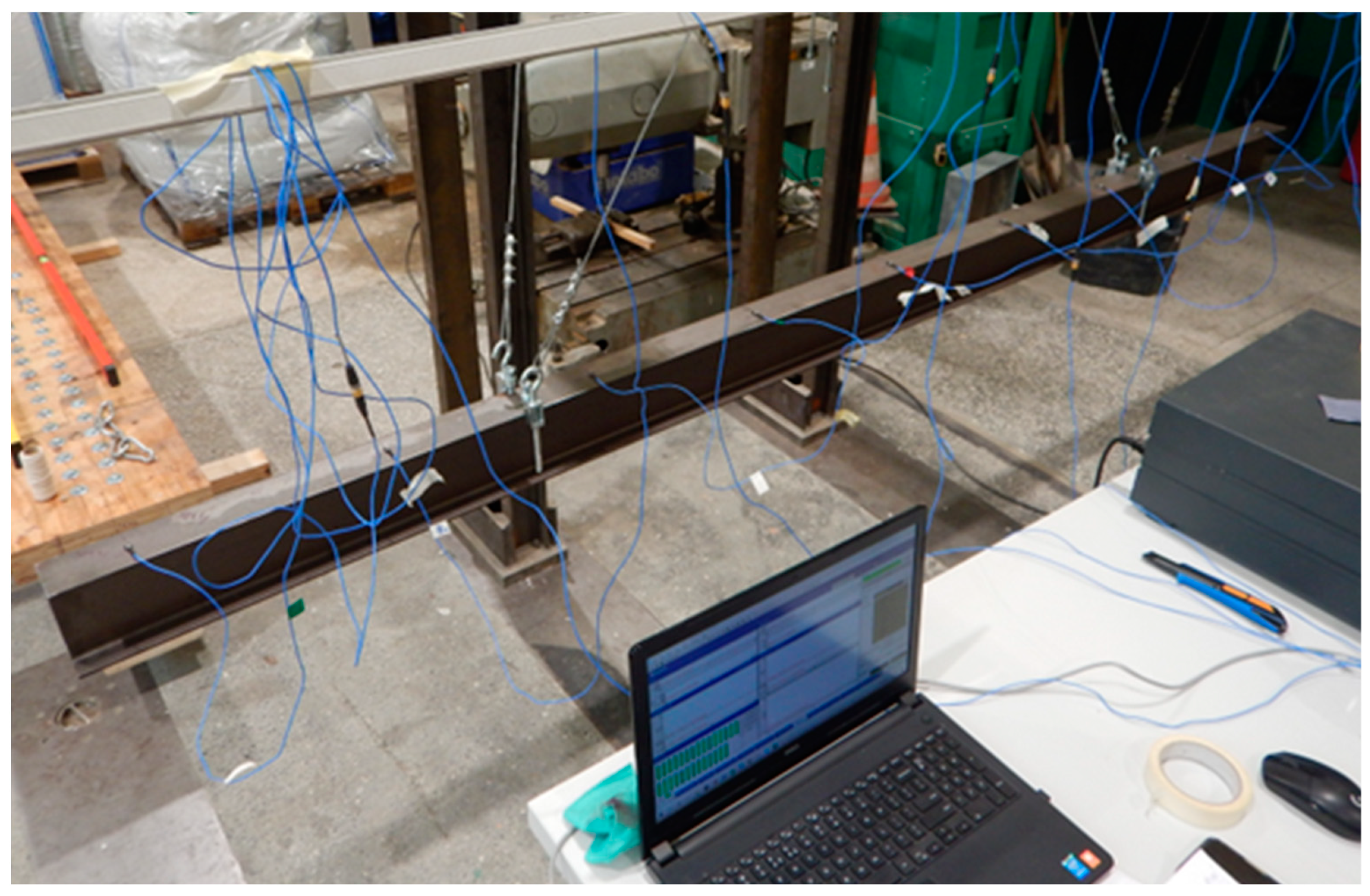
Figure 2.
The locations of the impact hammer and the accelerometers on the steel girder (nominal dimensions).
Figure 2.
The locations of the impact hammer and the accelerometers on the steel girder (nominal dimensions).
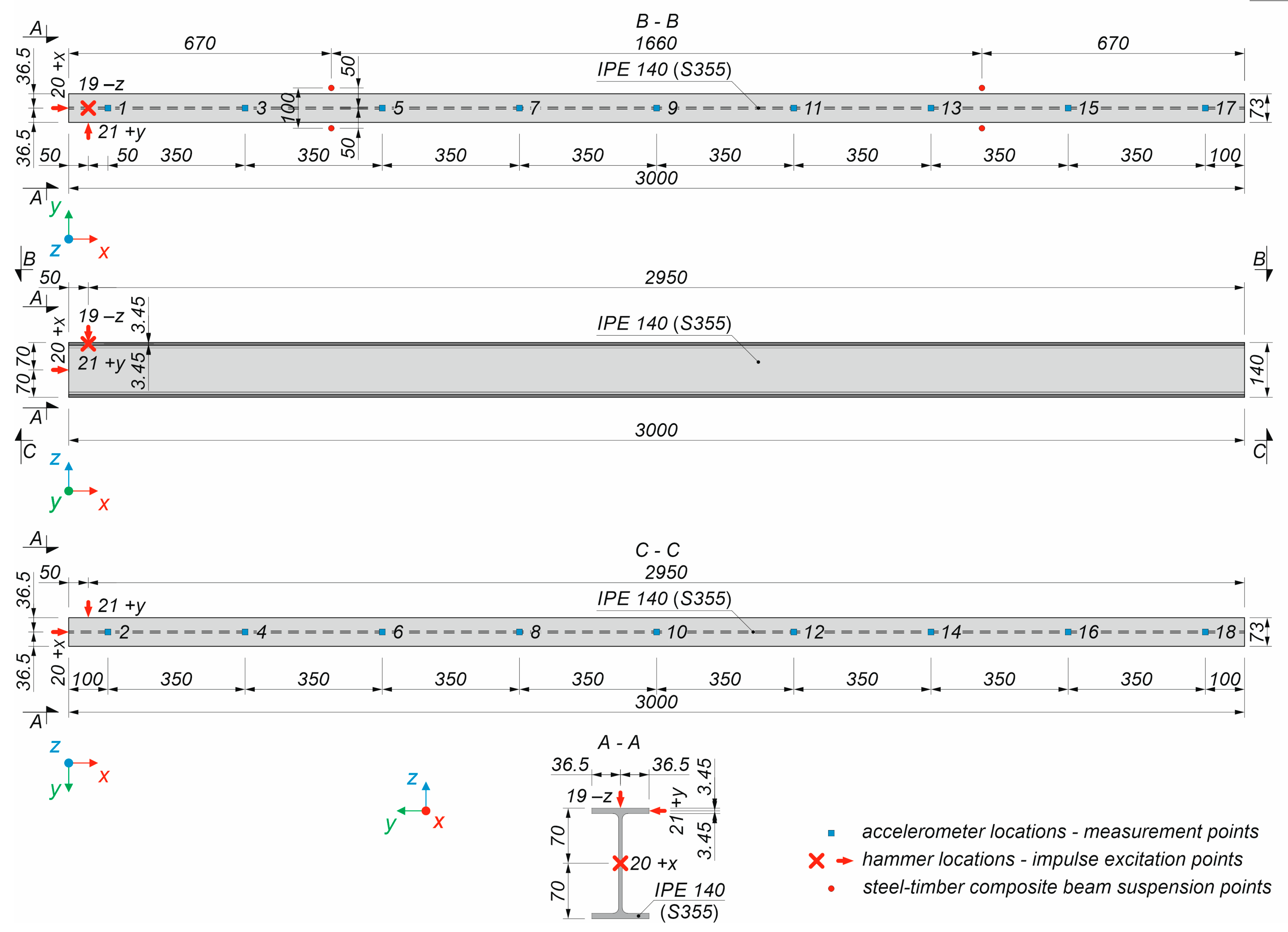
Figure 3.
(a) The impact hammer; (b) the accelerometer.
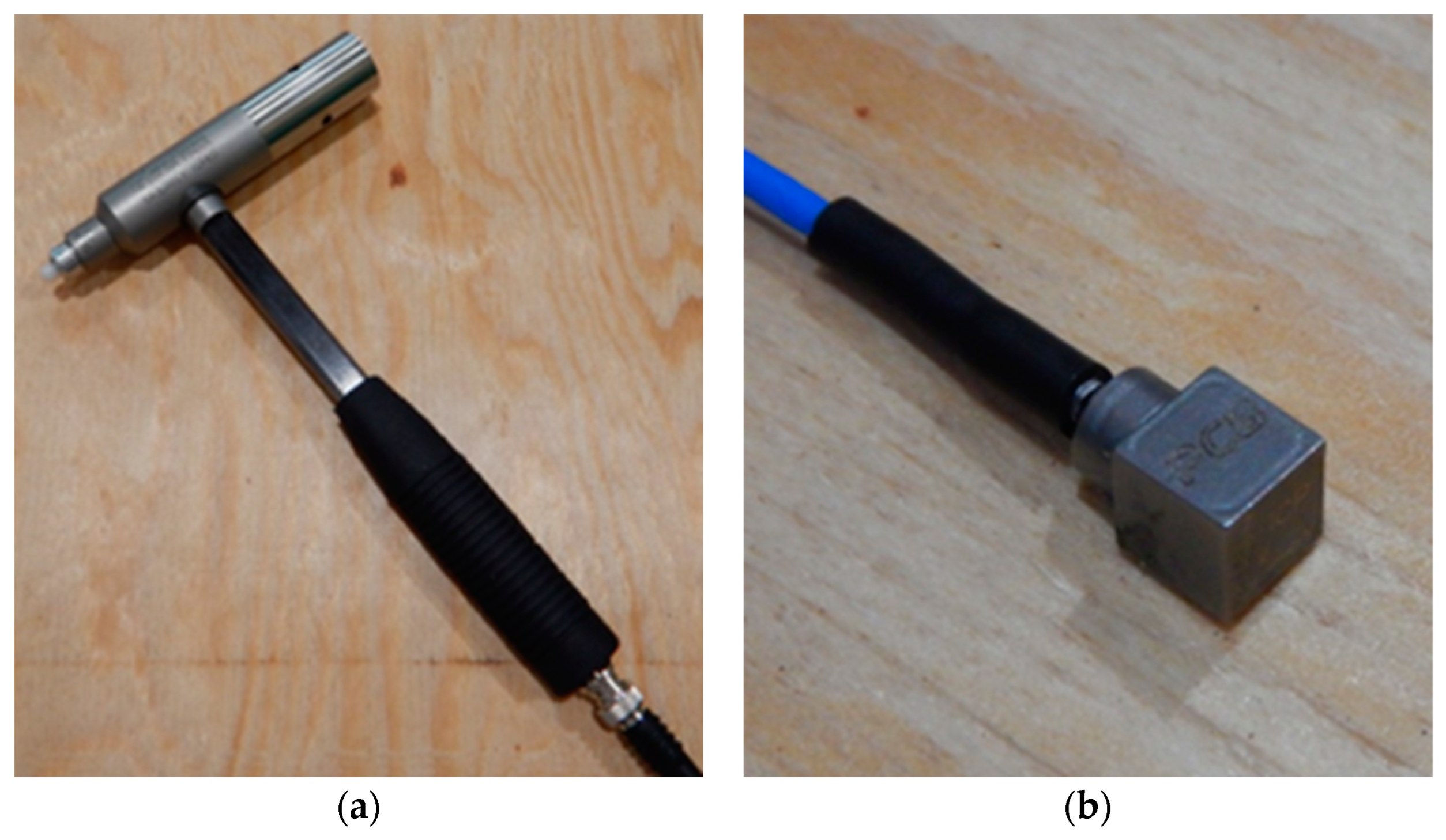
Figure 4.
The analysed steel–timber composite beams subjected to dynamic laboratory tests (nominal dimensions).
Figure 4.
The analysed steel–timber composite beams subjected to dynamic laboratory tests (nominal dimensions).
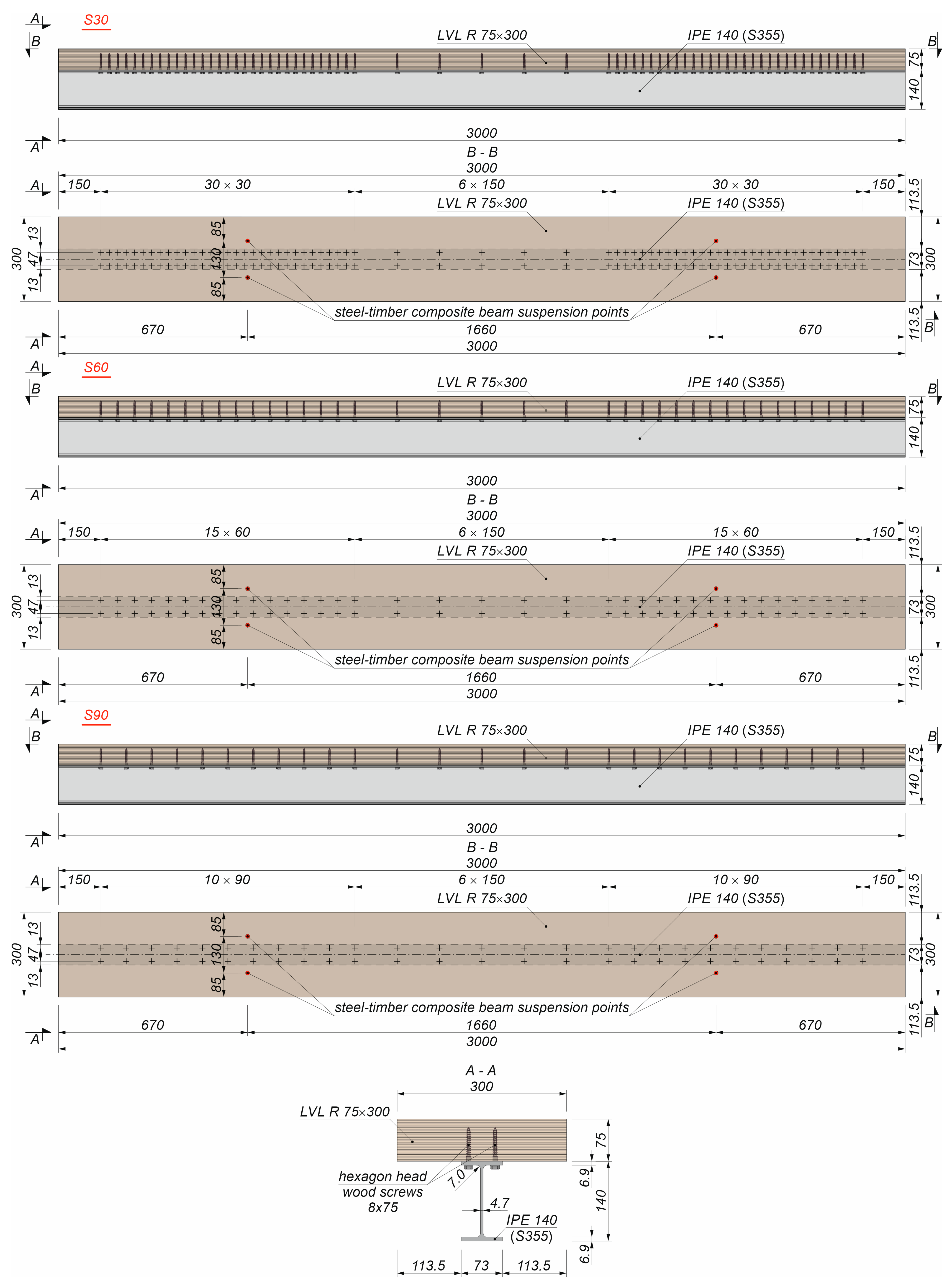
Figure 5.
One of the steel–timber composite beams suspended from the stand frame: (a) view from above; (b) view from below.
Figure 5.
One of the steel–timber composite beams suspended from the stand frame: (a) view from above; (b) view from below.

Figure 6.
The locations of the impact hammer and the accelerometer on the steel–timber composite beams (nominal dimensions).
Figure 6.
The locations of the impact hammer and the accelerometer on the steel–timber composite beams (nominal dimensions).
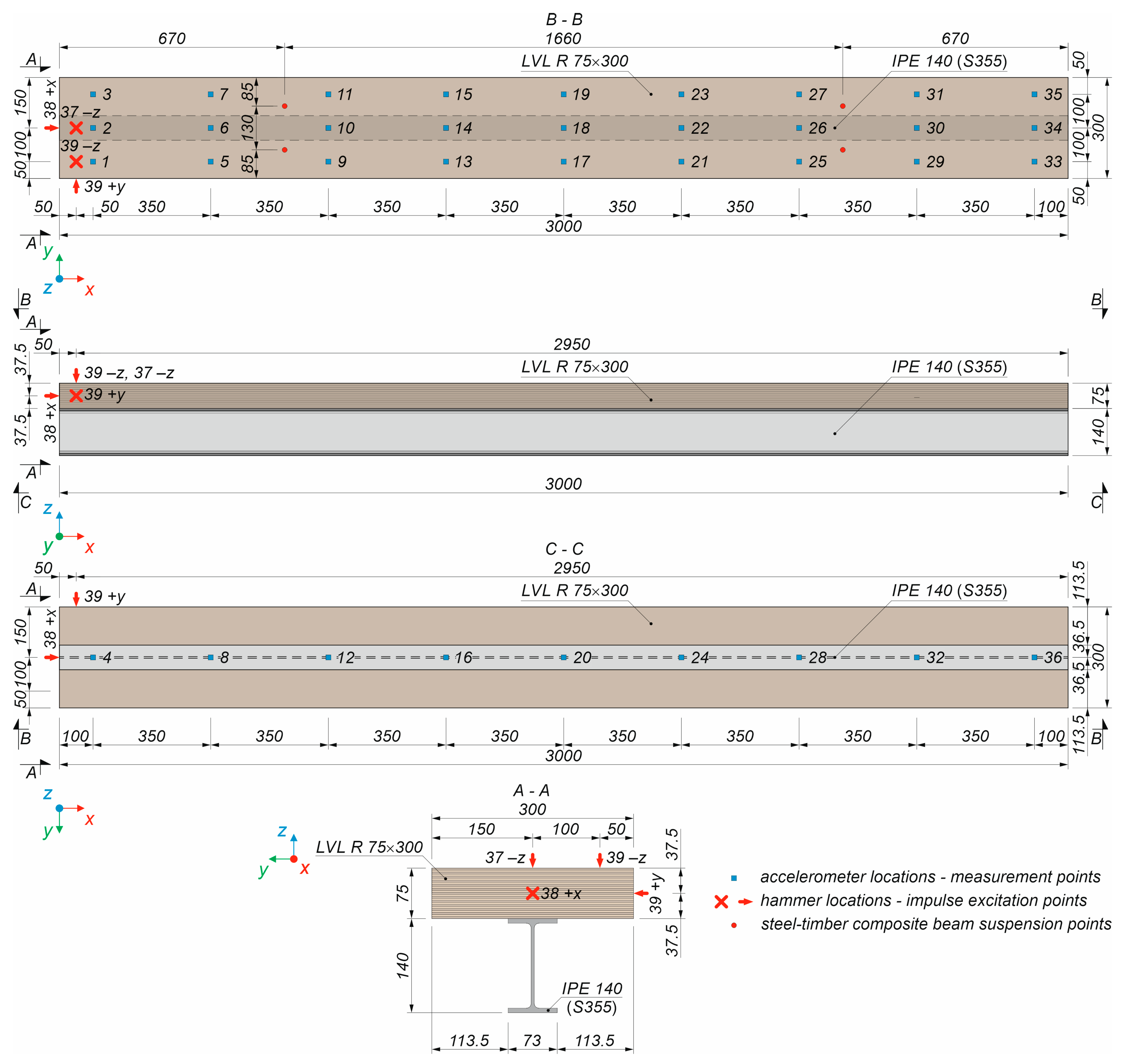
Figure 7.
One of the steel–timber composite beams: (a) view from the front; (b) girder-to-LVL slab connection.
Figure 7.
One of the steel–timber composite beams: (a) view from the front; (b) girder-to-LVL slab connection.
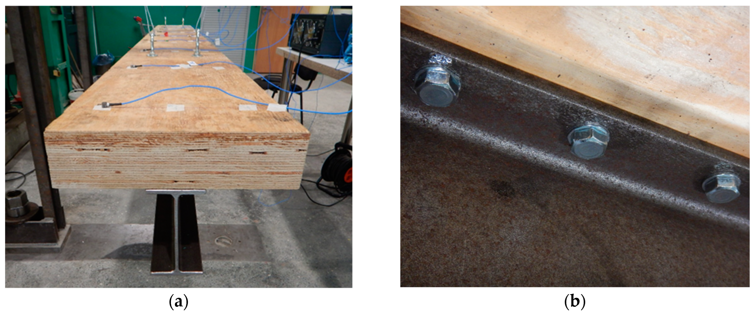
Figure 8.
The numerical model of the steel–timber composite beam: (a) general view; (b) rigid connection between the steel girder and the LVL slab; (c) discreet connectors between the steel girder and the LVL slab; (d) beam elements.
Figure 8.
The numerical model of the steel–timber composite beam: (a) general view; (b) rigid connection between the steel girder and the LVL slab; (c) discreet connectors between the steel girder and the LVL slab; (d) beam elements.

Figure 9.
The vibration modes of the steel girder obtained from the experimental test and the numerical analysis (model D).
Figure 9.
The vibration modes of the steel girder obtained from the experimental test and the numerical analysis (model D).
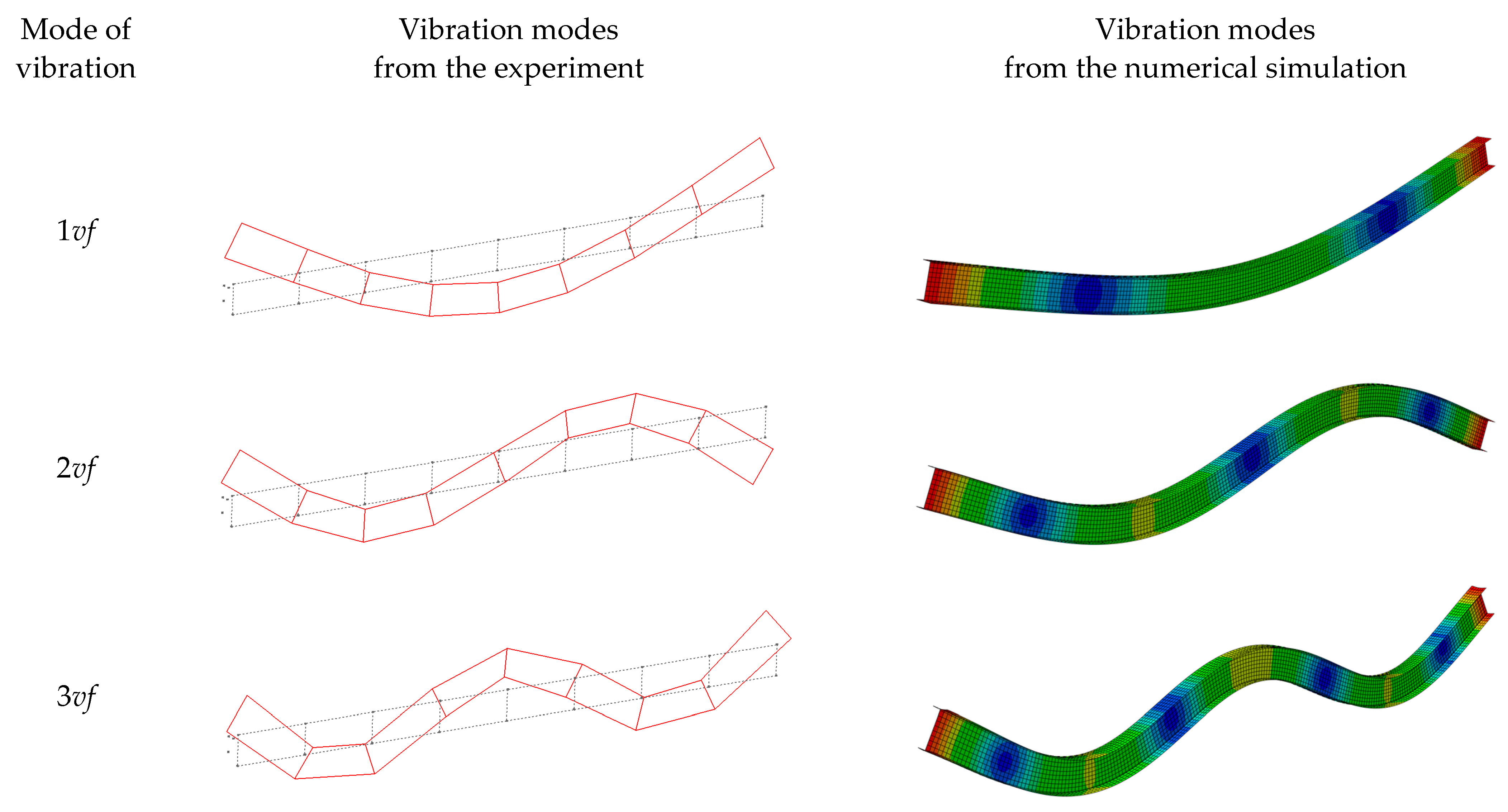
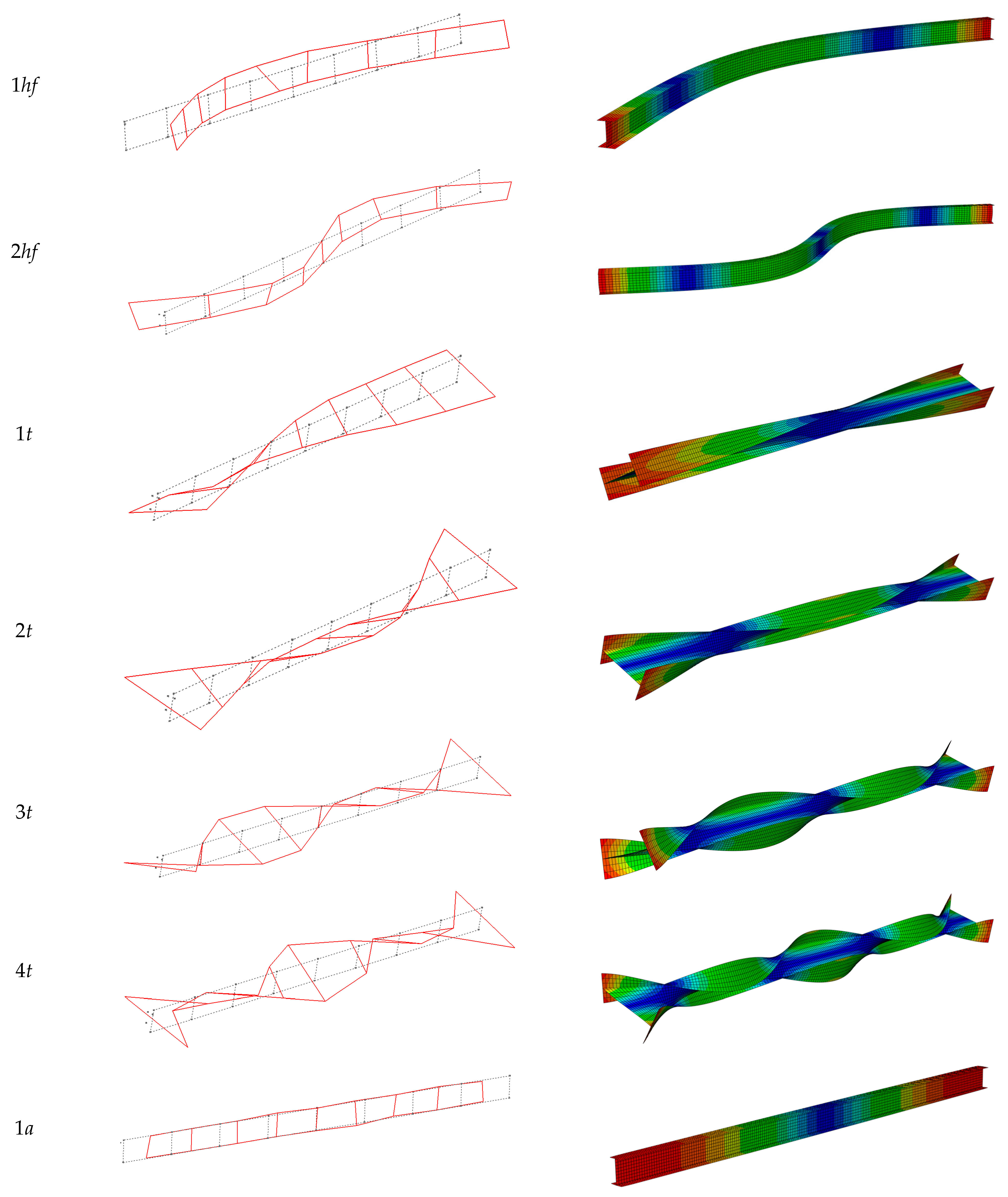
Figure 10.
A 3D MAC plot for the steel girder.

Figure 11.
A MAC matrix for the steel girder.

Figure 12.
The vibration modes of the S90 steel–timber composite beam in the experimental test and in the numerical analyses.
Figure 12.
The vibration modes of the S90 steel–timber composite beam in the experimental test and in the numerical analyses.
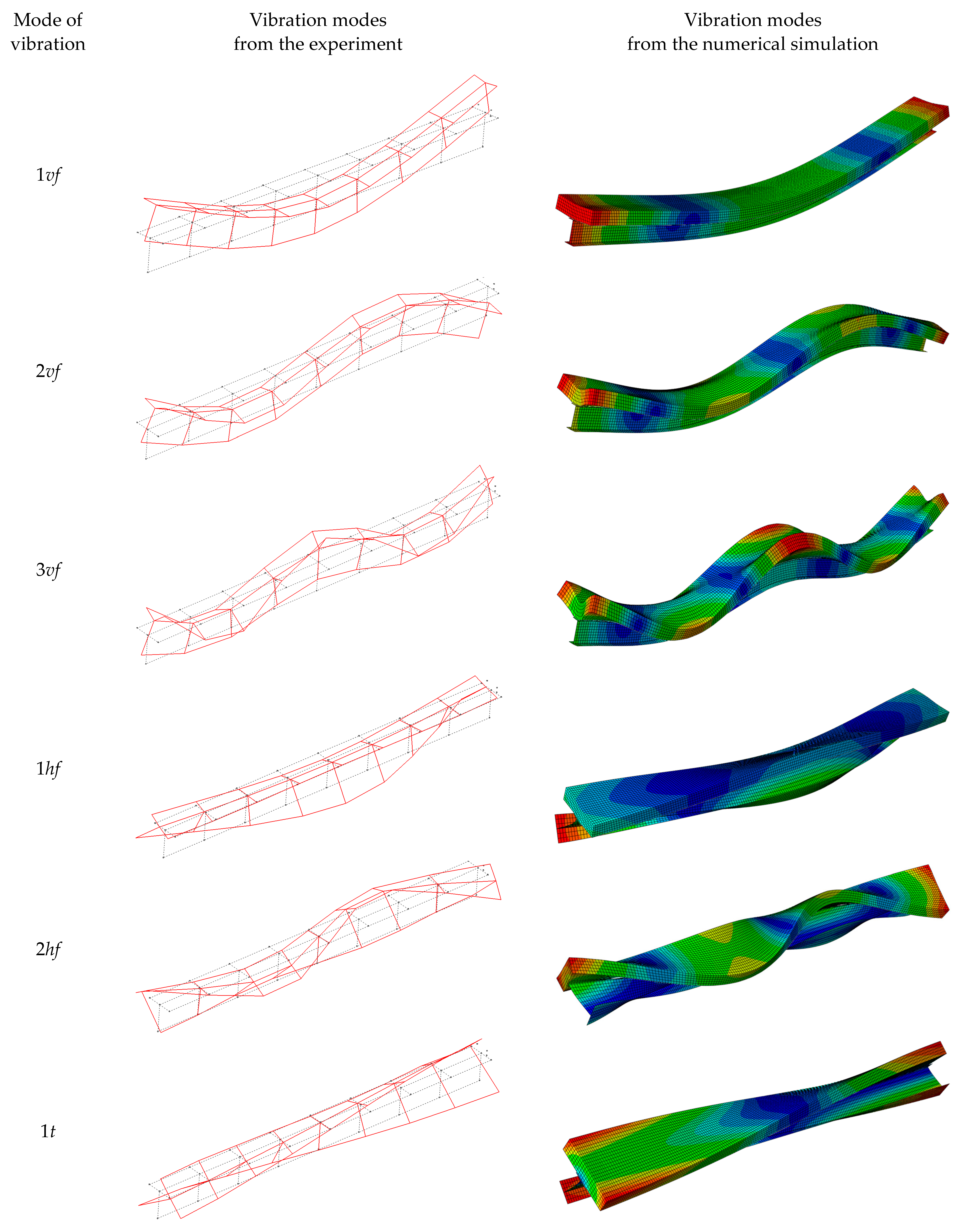

Figure 13.
Three-dimensional MAC plots for the steel–timber composite beams: (a) S30 (tie function); (b) S30; (c) S60; (d) S90.
Figure 13.
Three-dimensional MAC plots for the steel–timber composite beams: (a) S30 (tie function); (b) S30; (c) S60; (d) S90.
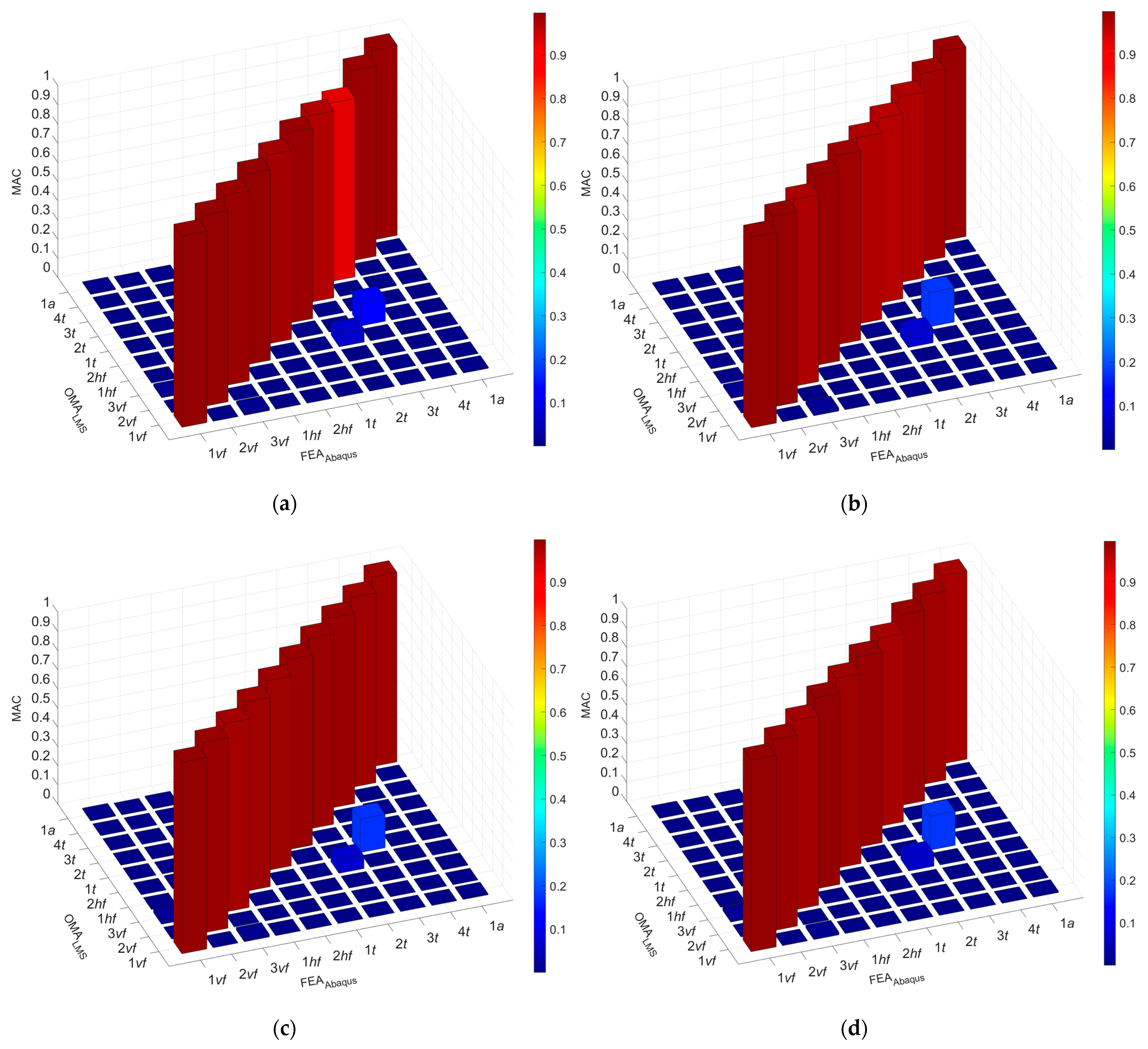
Figure 14.
MAC matrixes for the steel–timber composite beams: (a) S30 (tie function); (b) S30; (c) S60; (d) S90.
Figure 14.
MAC matrixes for the steel–timber composite beams: (a) S30 (tie function); (b) S30; (c) S60; (d) S90.


| Elastic Modulus [MPa] | Poisson’s Ratio [–] | Shear Modulus [MPa] | Density [kg/m3] | ||||||
|---|---|---|---|---|---|---|---|---|---|
| E1 | E2 | E3 | υ12 | υ13 | υ23 | G12 | G13 | G23 | ρ |
| 17,550 | 500 | 500 | 0.48 | 0.48 | 0.22 | 1000 | 1000 | 100 | 665.2 |
Table 2.
Chemical composition of the steel [%] [42].
Table 2.
Chemical composition of the steel [%] [42].
| C | Mn | Si | P | S | Cu | Cr | Ni |
|---|---|---|---|---|---|---|---|
| 0.10 | 1.32 | 0.19 | 0.018 | 0.026 | 0.28 | 0.11 | 0.08 |
| Mo | Ti | V | Al | N | Nb | Sb | Co |
| 0.01 | 0.001 | 0.070 | 0.0036 | 0.009 | 0.002 | 0.003 | 0.008 |
Table 3.
Steel girder dimensions.
| Catalogue Dimensions [43] | Measured Dimensions | |
|---|---|---|
 |  | |
| moment of inertia, Jx [cm4] | 2.48 | 2.49 |
| moment of inertia, Jy [cm4] | 541 | 529.6 |
| moment of inertia, Jz [cm2] | 44.9 | 47.3 |
| cross-sectional area, A [cm2] | 16.4 | 16.7 |
Table 4.
The methods of steel girder modelling using shell elements.
| Model A | Model B | Model C | Model D | |
|---|---|---|---|---|
 |  |  |  | |
| moment of inertia Jx [cm4] | 2.05 | 2.08 | 2.02 | 2.54 |
| moment of inertia Jy [cm4] | 527.8 | 543.0 | 514.1 | 537.4 |
| moment of inertia Jz [cm2] | 47.2 | 47.3 | 47.2 | 47.4 |
| cross-sectional area A [cm2] | 16.62 | 16.95 | 16.28 | 16.92 |
Table 5.
A comparison of the steel girder frequencies obtained from the experiments and the numerical simulations.
Table 5.
A comparison of the steel girder frequencies obtained from the experiments and the numerical simulations.
| Mode of Vibration | Experimental Frequency fexp [Hz] | Computational Frequency fcom | |||||||
|---|---|---|---|---|---|---|---|---|---|
| Model A [Hz] | (∆) [%] | Model B [Hz] | (∆) [%] | Model C [Hz] | (∆) [%] | Model D [Hz] | (∆) [%] | ||
| 1vf | 113.10 | 112.03 | (0.95) | 112.30 | (0.71) | 111.82 | (1.13) | 112.13 | (0.86) |
| 2vf | 293.93 | 294.87 | (−0.32) | 294.70 | (−0.26) | 294.88 | (−0.32) | 295.55 | (−0.55) |
| 3vf | 540.26 | 542.87 | (−0.48) | 540.70 | (−0.08) | 544.12 | (−0.71) | 545.04 | (−0.88) |
| 1hf | 33.80 | 33.81 | (−0.05) | 33.48 | (0.93) | 34.15 | (−1.05) | 33.58 | (0.64) |
| 2hf | 91.72 | 92.76 | (−1.14) | 91.91 | (−0.21) | 93.62 | (−2.07) | 92.07 | (−0.38) |
| 1t | 37.95 | 32.68 | (13.89) | 31.24 | (17.67) | 34.37 | (9.42) | 34.82 | (8.98) |
| 2t | 82.81 | 76.31 | (7.85) | 72.85 | (12.03) | 80.28 | (3.06) | 80.71 | (2.60) |
| 3t | 147.20 | 142.94 | (2.89) | 136.38 | (7.35) | 150.22 | (−2.05) | 149.66 | (−1.64) |
| 4t | 233.49 | 239.57 | (2.60) | 228.66 | (2.07) | 251.38 | (−7.66) | 248.80 | (−6.15) |
| 1a | 857.48 | 857.37 | (0.01) | 857.38 | (0.01) | 857.33 | (0.02) | 857.33 | (0.02) |
| S ∙ 10−2 [−] | 2.72 | 5.17 | 1.68 | 1.30 | |||||
Table 6.
The comparison between the frequencies obtained in the numerical analyses of the model with the rigid connection (tie function) and those from the laboratory tests.
Table 6.
The comparison between the frequencies obtained in the numerical analyses of the model with the rigid connection (tie function) and those from the laboratory tests.
| Mode of Vibration | Computational Frequency fcom [Hz] | Experimental Frequency fexp | |||||
|---|---|---|---|---|---|---|---|
| Beam S30 [Hz] | (∆) [%] | Beam S60 [Hz] | (∆) [%] | Beam S90 [Hz] | (∆) [%] | ||
| 1vf | 128.54 | 126.25 | (−1.82) | 127.73 | (−0.64) | 126.65 | (−1.49) |
| 2vf | 305.68 | 293.78 | (−4.05) | 298.30 | (−2.48) | 297.59 | (−2.72) |
| 3vf | 488.49 | 463.74 | (−5.34) | 475.01 | (−2.84) | 469.90 | (−3.96) |
| 1hf | 100.65 | 96.79 | (−3.98) | 97.67 | (−3.06) | 96.07 | (−4.77) |
| 2hf | 320.17 | 310.32 | (−3.17) | 313.75 | (−2.05) | 309.60 | (−3.41) |
| 1t | 76.09 | 71.97 | (−5.72) | 72.84 | (−4.46) | 71.88 | (−5.86) |
| 2t | 266.70 | 251.58 | (−6.01) | 254.65 | (−4.73) | 253.06 | (−5.39) |
| 3t | 368.38 | 338.46 | (−8.84) | 342.96 | (−7.41) | 341.00 | (−8.03) |
| 4t | 471.27 | 440.15 | (−7.07) | 448.35 | (−5.11) | 441.75 | (−6.68) |
| 1a | 855.95 | 837.82 | (−2.16) | 854.51 | (−0.17) | 842.68 | (−1.57) |
| S ∙ 10−2 [−] | 1.40 | 1.51 | 2.35 | ||||
Table 7.
A comparison between the frequencies obtained in the numerical analyses of the model with the discreet connectors and those from the laboratory tests.
Table 7.
A comparison between the frequencies obtained in the numerical analyses of the model with the discreet connectors and those from the laboratory tests.
| Mode of Vibration | Beam S30 | Beam S60 | Beam S90 | ||||||
|---|---|---|---|---|---|---|---|---|---|
| fexp [Hz] | fcom [Hz] | (∆) [%] | fexp [Hz] | fcom [Hz] | (∆) [%] | fexp [Hz] | fcom [Hz] | (∆) [%] | |
| 1vf | 126.25 | 126.74 | (−0.39) | 127.73 | 127.24 | (0.38) | 126.65 | 127.39 | (−0.58) |
| 2vf | 293.78 | 299.09 | (−1.81) | 298.30 | 300.76 | (−0.83) | 297.59 | 301.22 | (−1.22) |
| 3vf | 463.74 | 479.81 | (−3.47) | 475.01 | 481.00 | (−1.26) | 469.90 | 481.09 | (−2.38) |
| 1hf | 96.79 | 98.61 | (−1.87) | 97.67 | 98.59 | (−0.95) | 96.07 | 98.563 | (−2.59) |
| 2hf | 310.32 | 313.75 | (−1.11) | 313.75 | 316.58 | (−0.90) | 309.60 | 317.45 | (−2.54) |
| 1t | 71.97 | 73.00 | (−1.43) | 72.84 | 73.11 | (−0.36) | 71.88 | 73.131 | (−1.74) |
| 2t | 251.58 | 260.85 | (−3.68) | 254.65 | 260.64 | (−2.35) | 253.06 | 260.5 | (−2.94) |
| 3t | 338.46 | 350.63 | (−3.60) | 342.96 | 350.60 | (−2.23) | 341.00 | 350.52 | (−2.79) |
| 4t | 440.15 | 461.68 | (−4.89) | 448.35 | 461.71 | (−2.98) | 441.75 | 461.6 | (−4.49) |
| 1a | 837.82 | 845.96 | (−0.97) | 854.51 | 857.18 | (−0.31) | 842.68 | 858.51 | (−1.88) |
| S ∙ 10−2 [−] | 0.74 | 0.24 | 0.64 | ||||||
Disclaimer/Publisher’s Note: The statements, opinions and data contained in all publications are solely those of the individual author(s) and contributor(s) and not of MDPI and/or the editor(s). MDPI and/or the editor(s) disclaim responsibility for any injury to people or property resulting from any ideas, methods, instructions or products referred to in the content. |
© 2024 by the authors. Licensee MDPI, Basel, Switzerland. This article is an open access article distributed under the terms and conditions of the Creative Commons Attribution (CC BY) license (https://creativecommons.org/licenses/by/4.0/).
Share and Cite
MDPI and ACS Style
Abramowicz, M.; Chybiński, M.; Polus, Ł.; Szewczyk, P.; Wróblewski, T. Dynamic Response of Steel–Timber Composite Beams with Varying Screw Spacing. Sustainability 2024, 16, 3654. https://doi.org/10.3390/su16093654
AMA Style
Abramowicz M, Chybiński M, Polus Ł, Szewczyk P, Wróblewski T. Dynamic Response of Steel–Timber Composite Beams with Varying Screw Spacing. Sustainability. 2024; 16(9):3654. https://doi.org/10.3390/su16093654
Chicago/Turabian StyleAbramowicz, Małgorzata, Marcin Chybiński, Łukasz Polus, Piotr Szewczyk, and Tomasz Wróblewski. 2024. "Dynamic Response of Steel–Timber Composite Beams with Varying Screw Spacing" Sustainability 16, no. 9: 3654. https://doi.org/10.3390/su16093654
Note that from the first issue of 2016, this journal uses article numbers instead of page numbers. See further details here.