Article

Adaptive Equivalent Fuel Consumption Minimization Based Energy Management Strategy for Extended-Range Electric Vehicle

1
College of Energy Engineering, Zhejiang University, Hangzhou 310027, China
2
Key Laboratory of Smart Thermal Management Science & Technology for Vehicles of Zhejiang Province, Taizhou 317200, China
3
Hangzhou DV Technology Co., Ltd., Hangzhou 310023, China
*
Author to whom correspondence should be addressed.
Sustainability 2023, 15(5), 4607; https://doi.org/10.3390/su15054607
Submission received: 8 January 2023 / Revised: 25 February 2023 / Accepted: 1 March 2023 / Published: 4 March 2023
(This article belongs to the Special Issue Reaching Net Zero—Energy Conversion and Storage Systems)

Abstract

:
Unlike battery electric vehicles, extended-range electric vehicles have one more energy source, so a reasonable energy management strategy (EMS) is crucial to the fuel economy of the vehicles. In this paper, an adaptive equivalent fuel consumption minimization strategy (A-ECMS)-based energy management strategy is proposed for the extended-range electric vehicle. The equivalent fuel consumption minimization strategy (ECMS), which utilizes Pontryagin’s minimum principle (PMP), is introduced to design the EMS. Compared with other ECMS strategies, an adaptive equivalent factor algorithm, based on state of charge (SOC) feedback and a proportional–integral (PI) controller is designed to update the equivalent factor under different working conditions. Additionally, a start–stop penalty is added to the objective function to take the dynamic start–stop process of the range extender into account. As a result, under the WLTC driving cycle, the proposed strategy can achieve 6.78 L/100 km comprehensive fuel consumption, saving 6.2% and 3.4% fuel consumption compared with the conventional rule-based thermostat strategy and the power following strategy. Moreover, the proposed EMS achieves the lowest ampere-hour flux among the three EMSs, indicating its ability to improve battery life.

1. Introduction

The extended-range electric vehicle is an important branch of new energy vehicles. It has attracted widespread attention in the industry because of its two main advantages: high efficiency in terms of a full-time electric drive and causing no anxiety about mileage and charging. The powertrain of an extended-range electric vehicle generally includes a power battery, a drive motor, and a range extender, which is composed of an engine and an integrated starter generator (ISG) motor with both power generation and electric drive functions.
The energy management strategy (EMS) is the core of the powertrain control of extended-range electric vehicles, which optimizes the power split among multiple energy sources under the premise that the powertrain meets driving needs, and helps to achieve lower fuel consumption, longer battery life, lower emissions and better NVH performance [1]. Commonly used EMSs can be divided into three main categories: rule-based EMSs, optimization-based EMSs and learning-based EMSs. Rule-based EMSs are often developed based on engineering experience or test calibration, with mediocre effects and poor adaptability to changing working conditions. With the development of computer technology, the method, based on deep learning, is gradually applied to the field of energy systems [2,3]. The performance of learning-based EMSs depends on the scale of training data and the structure of the neural network model. Because super computing power and the information provided by the intelligent transportation system are required, the application of the current on-board computing units is still a problem for learning-based EMSs. Optimization-based EMSs mainly have two categories: global optimization-based EMSs and instantaneous optimization-based EMSs. Among them, the EMS based on global optimization needs to predict global working conditions and cannot be applied in real-time. The EMS based on the instantaneous optimization algorithm includes the equivalent fuel consumption minimum strategy (ECMS), model predictive control (MPC) and other methods [4,5], aiming to solve the problem of real-time application while ensuring the effectiveness of energy management.
However, the effect of the MPC-based EMS depends on the accuracy of the predictive model [6], and is limited by the computing ability of the controller hardware, which results in the difficulty of real-time application. ECMS unifies the instantaneous fuel consumption and the power consumption into equivalent fuel consumption through the equivalent factor, and solves the optimal control variable by minimizing the instantaneous equivalent fuel consumption, which shows the advantage of fast calculation. Therefore, ECMS became a research hotspot for instantaneous optimization-based EMSs [7,8,9,10,11]. Huang [12] et al. proposed an ECMS with minimum fuel consumption and the state of charge (SOC) balance as the optimization objective. Compared with the rule-based strategy, the fuel consumption rate of the ECMS was reduced by 23.09%. Rezaei [13] et al. studied the ECMS for parallel hybrid vehicles, and deduced the upper and lower bounds of the optimal equivalent factor; the simulation showed that the optimal equivalent factor was always within or close to the upper and lower bounds. Xie [14] et al. tried an artificial neural network-involved equivalent fuel consumption minimization strategy (ANN-ECMS). The simulation of different initial SOCs showed that the ANN-ECMS had a similar fuel efficiency to global optimization methods such as dynamic programming (DP) and Pontryagin’s minimum principle (PMP), and the energy consumption was significantly reduced compared with rule-based EMSs. With the help of the intelligent transportation system, Liu [15] et al. took into account characteristics of the driver and adjusted the equivalent factor of the ECMS, so that the ECMS could be applied in real-time. Then they verified the feasibility and effectiveness of the strategy through simulation.
According to recent studies [16,17,18,19,20], the adaptive adjustment of the equivalent factor greatly influences the effect of ECMS. However, due to the uncertainty of the future working conditions of the vehicle and different optimization goals, the research on the adaptive adjustment of the equivalent factor needs to be in-depth. In addition, the existing literature seldom considers the negative impact of the frequent start–stop of the range extender. Considering features of the extended-range electric vehicle and dynamic response characteristics of the power generation of the range extender, this paper takes a certain type of extended-range electric vehicle as the research object. Moreover, an adaptive equivalent fuel consumption minimization strategy (A-ECMS) using the SOC feedback proportional–integral (PI) controller is designed based on the existing ECMS. The dynamic start–stop process of the range extender is considered, and a start–stop penalty item is added to the Hamiltonian function to further optimize the performance of the proposed A-ECMS. After that, strategy parameters are determined based on the vehicle simulation platform. Finally, the effect of the strategy is verified and compared with other strategies.

2. Adaptive ECMS Energy Management Strategy

2.1. Mathematical Description of ECMS

This paper studies the EMS for the charge-sustaining (CS) mode of the extended-range electric vehicle. The optimization goal can be described as follows: by controlling the power generation of the range extender, the overall fuel consumption is minimized, and at the same time, the battery SOC can reach the target as close as possible at the end of the cycle.
Taking the power generation of the range extender as the control variable and the SOC as the state variable, the augmented cost function can be written as follows:
J ( t f ) = t 0 t f m ˙ f ( P RE ) d t + ϕ ( S O C t f S O C target )
where m ˙ f is the instantaneous fuel consumption rate of the engine, kg/s; P RE is the target power generation of the range extender, kW; S O C t f is the SOC at the end of the cycle, %; S O C target is the target SOC, %; and ϕ is the penalty coefficient for the deviation of S O C t f and S O C target .
ECMS is a instantaneous optimization method derived from PMP. It uses the equivalent factor to equate the power consumption to the fuel consumption, plus the fuel consumption of the engine to get the equivalent fuel consumption, then solves the optimization problem of minimizing the equivalent fuel consumption rate to obtain the optimal control variables.
Ignoring the accessories’ energy consumption, the equivalent fuel consumption rate can be calculated by Equation (2):
m ˙ eqv = m ˙ f + m ˙ e = m ˙ f + s P bat H LHV
where m ˙ eqv is the equivalent fuel consumption rate, kg/s; m ˙ e is the equivalent fuel consumption rate converted from power consumption, kg/s; P bat is the output power of the battery, kW; H LHV is the low heating value of the fuel, kJ/kg; and s is the equivalent factor, which reflects the conversion cost of fuel and electricity.
PMP is a numerical optimization method with definite solutions. By analysing the relationship between ECMS and PMP, a certain theoretical basis for the determination of the equivalent factor can be provided. According to PMP and Equation (1), the co-state variable λ is introduced, and the Hamiltonian function is constructed as follows:
H [ S O C ( t ) , P RE ( t ) , λ ( t ) , t ] = m ˙ f [ P RE ( t ) ] + λ ( t ) S O C ( t ) = m ˙ f ( t ) λ ( t ) P bat ( t ) η bat sign ( P bat ) Q bat U oc
where U oc is the open circuit voltage of the power battery, V; P bat is the charging and discharging power of the battery, kW; η bat is the charging and discharging efficiency; and Q bat is the rated capacity of the battery, Ah.
The optimal control variables are obtained by solving the following equation:
P RE ( t ) = argmin { H [ S O C ( t ) , P RE ( t ) , λ ( t ) , t ] } , P RE U P RE
where P RE ( t ) is the optimal power generation of the range extender, kW; and U P RE is the feasible region of the power generation of the range extender.
In general, Equation (2) of the ECMS is very similar to the Hamiltonian Function (3) of PMP, and the second term of the Hamiltonian function can be regarded as the equivalent instantaneous fuel consumption rate converted from the instantaneous power consumption rate. Therefore, based on PMP, the optimal control variables of the ECMS can be obtained by solving Equation (4). In the CS mode, the SOC variation range is small, and ignoring changes in SOC and temperature, the open circuit voltage of the battery and internal resistance can be regarded as constant. According to PMP, the optimal co-state variable in the Hamiltonian function can also be approximately regarded as constant. The relationship between the equivalent factor and the co-state variable can be derived from Equations (2) and (3), as follows:
s = H LHV η bat sign ( P bat ) Q bat U oc λ ( t )
s chg = η bat 2 s dis
where s chg is the charging equivalent factor, s dis is the discharging equivalent factor.
The equivalent factor reflects the future conversion efficiency of fuel and electric energy, and its selection greatly affects the performance of the ECMS. However, the future driving conditions are generally unknown, and there are many influencing factors. Therefore, it is difficult to determine the equivalent factor according to different optimization objectives.

2.2. Adaptive Adjustment of Equivalent Factor

With the changing of the working conditions, it is difficult to maintain the SOC to the target value by a fixed equivalent factor, so it is necessary to adjust the equivalent factor in real-time. Considering that the extended-range electric vehicle system is discrete, a discrete PI controller based on SOC feedback is used to update the equivalent factor in real-time. To simplify the description, the adaptive equivalent factors described below are all discharging equivalent factors. The adaptive equivalent factor consists of the initial equivalent factor and the adaptive term, which can be expressed as follows:
s ( t ) = s 0 + K p [ S O C target S O C ( t ) ] + K i t 0 t f [ S O C target S O C ( t ) ] T s
where s 0 is the initial equivalent factor, K p is the proportional coefficient, K i is the integral coefficient, and T s is the system sampling time.
The first item s 0 in the equation is not only the initial value of the equivalent factor, but also a self-learning factor. That is to say, the s ( t 1 ) at the previous moment is taken as the s 0 of the current moment. This self-learning method reduces the computation burden of the look-up table model. The remaining two items are the SOC feedback adjustment items based on the PI controller, which prevent the SOC from deviating too much from the target value.

2.3. Penalty Item for Frequent Start and Stop of Range Extender

Due to the adaptive adjustment of the equivalent factor, the range extender may start and stop frequently, which is detrimental to vehicle performance [21]. Shigenori et al. [22] conducted a test on a 1.5 T inline four-cylinder engine and measured that the fuel consumption generated by one start was approximately equal to the fuel consumption generated by its idling running for 6.7 s. Because the specific fuel consumption at engine start is always high, frequent start and stop will lead to worse fuel economy. Additionally, it needs time for the range extender to respond to the command issued by the A-ECMS and change the power generation working points. If the engine starts and stops frequently, the working point will stay at the low efficiency area for a long time, which will result in high fuel consumption. To minimize the total energy consumption and reduce the start–stop times of the range extender, a penalty term for the start–stop of the range extender is added to the original Hamiltonian function, which makes the A-ECMS more reasonable.
The A-ECMS modified with kW as the unified dimension is as follows:
H ( t ) = { m ˙ f H LHV + s ( t ) P bat ( t ) + δ [ P RE ( t ) P RE ( t 1 ) ] , P bat ( t ) 0 m ˙ f H LHV + s ( t ) η bat 2 P bat ( t ) + δ [ P RE ( t ) P RE ( t 1 ) ] , P bat ( t ) < 0
P RE ( t ) = argmin [ H ( t ) ]
where s ( t ) is the adaptive equivalent factor; P RE ( t ) is the power generation of the range extender at the current moment, kW; P RE ( t 1 ) is the power generation of the range extender at the previous moment, kW; P bat ( t ) is the charging and discharging power of the battery, kW; and δ is the starting penalty factor of the range extender. When P RE ( t 1 ) > 0 , δ = 0 .
In addition, the following physical constraints must be enforced:
P REmin P RE P REmax
P batchrgmax P bat P batdischrgmax
where P REmin and P REmax denote the minimum and maximum power generation of the range extender, kW; and P batchrgmax and P batdischrgmax are the maximum charging and discharging power of the battery, kW.
The flow chart of the A-ECMS is shown in Figure 1, and the simulation test is implemented on vehicle simulation platform. Under the premise of meeting the vehicle power demand, the A-ECMS solves the optimal power generation of the range extender by minimizing the Hamiltonian function. In addition, the battery SOC is calculated through the control-oriented vehicle models, and the equivalent factor is updated based on the current SOC and feedback s 0 from the previous time. All the above steps are repeated until the end of the cycle.

3. Parameter Optimization of the A-ECMS

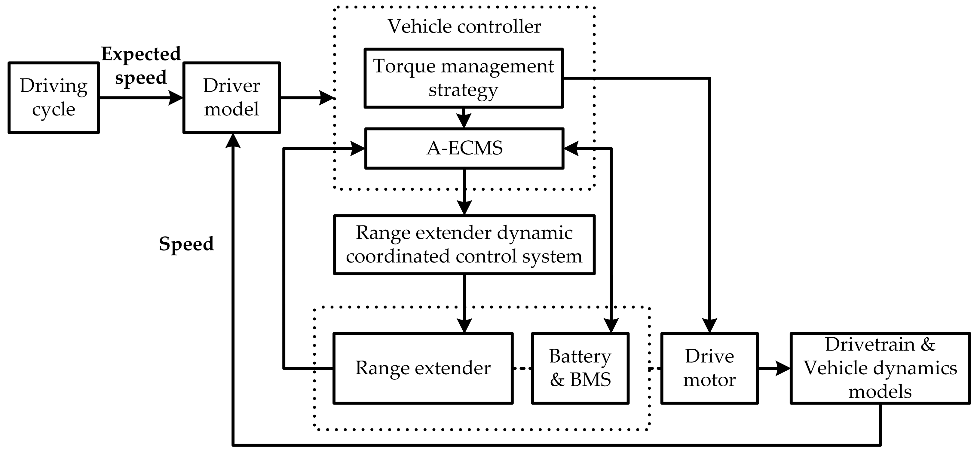
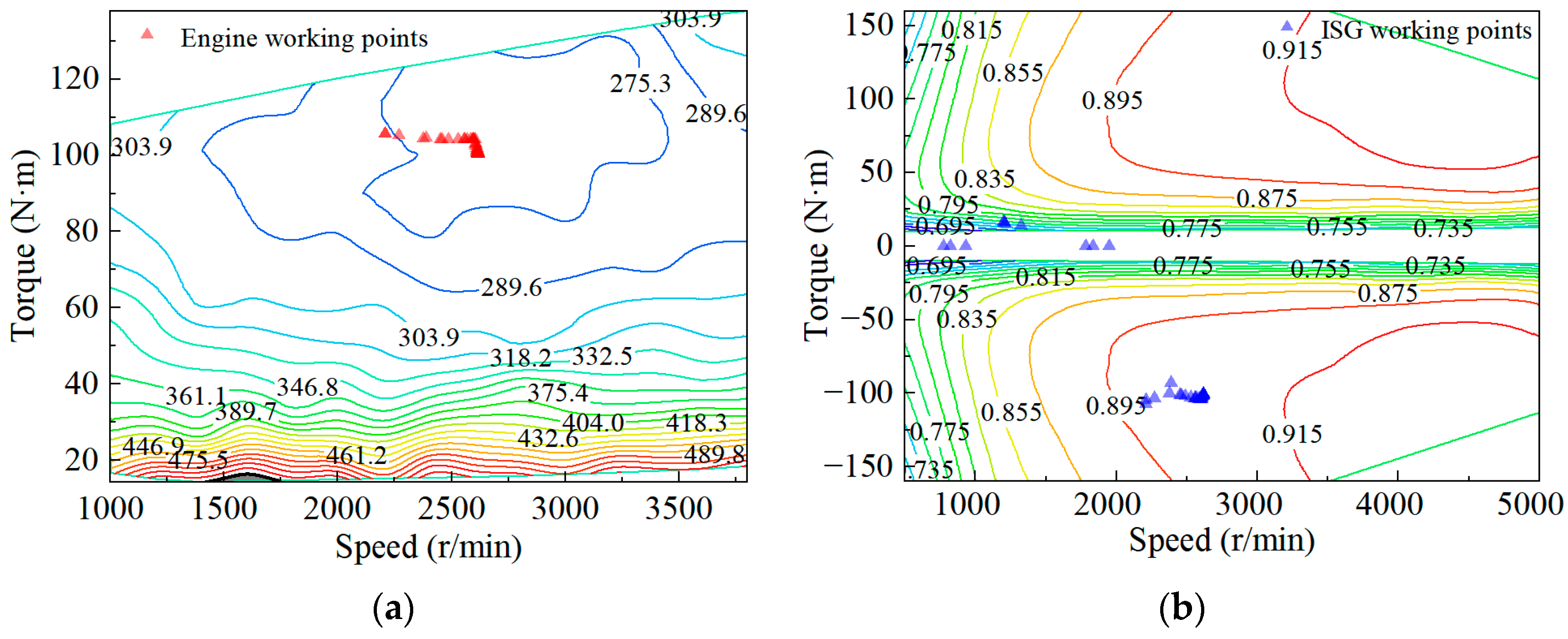
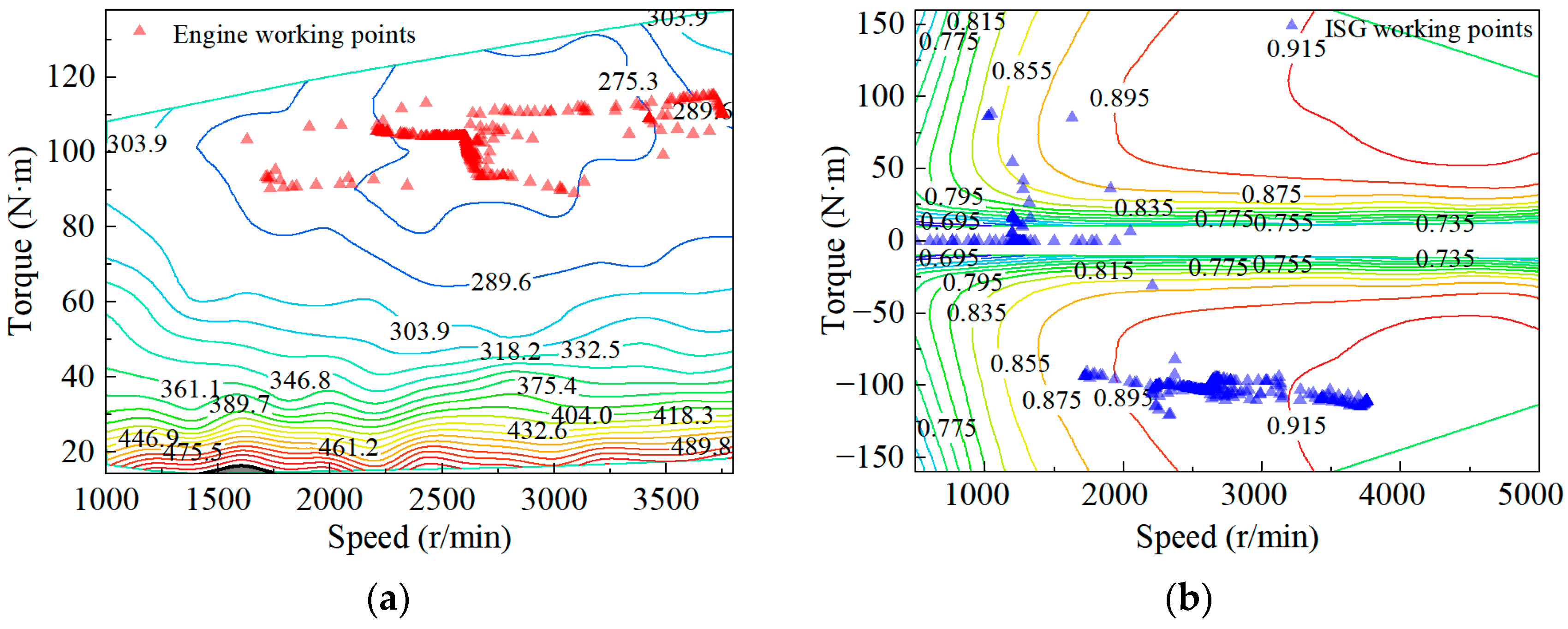
3.1. Vehicle Simulation Platform

To optimize the key parameters in the proposed A-ECMS strategy, a vehicle forward simulation model was built based on MATLAB/Simulink, taking a certain type of extended-range electric vehicle as a prototype. From Figure 2, its powertrain mainly includes an engine, an ISG motor, a battery and a drive motor. P mot is the power of the drive motor and P accessory is the power used for vehicle accessories, which can be supplied by both the battery and range extender. The main parameters of this extended-range electric vehicle are shown in Table 1. The range extender used in this vehicle is composed of a 1.5 L engine and a permanent magnet synchronous ISG motor with a maximum power of 60 kW. The fuel consumption in CS mode is about 7.1 L/100 km under the WLTC, and the battery capacity is 17.28 kWh.
As shown in Figure 3, the driver model in the vehicle simulation platform is a PID controller, which follows the vehicle target speed when running simulation tests. During the simulation, the driver model receives the driving cycle information and the current simulated vehicle speed, generates the accelerator pedal signals and brake pedal signals, and passes the signals to the vehicle controller. The vehicle target power is calculated according to the vehicle state and constraints. Then, the power split between the range extender and the battery is determined according to the A-ECMS. The target power generation of the range extender is decoupled by the dynamic coordination control system into a speed command and a torque command, which are sent to the engine controller and the ISG motor controller to respond, respectively. The energy source system, composed of the range extender and the battery, provides power to the drive motor. Then, the output torque of the drive motor is controlled by the torque management strategy of the vehicle controller, and the simulated vehicle speed is given through the drivetrain and vehicle dynamics models.
To verify the vehicle simulation platform, the test signal received by the prototype vehicle is used as the input and sent to the vehicle simulation platform to compare the model output with the test output. The initial SOC of the battery is set to 39.9%, the ambient temperature is set to 27 °C, the atmospheric pressure is set to 101 kPa, the road gradient is set to 0, and the wind speed is set to 0 m/s. The range extender model takes the speed, torque, start–stop and other commands issued by the vehicle controller hardware as input signals, and uses the output voltage of the power battery as the voltage at this time. The battery model takes the drive motor current and the output current of the range extender as input signals. Then, the drive motor model responds to the torque request command from the vehicle controller. Therefore, the simulation vehicle speed can be obtained according to the output torque of the drive motor and the vehicle longitudinal dynamic model.
It can be seen from Figure 4 that the range extender output power error is within ±2 kW, the battery SOC error is within ±0.25%, and the drive motor output torque error is within ±2 N·m. Considering the mechanical braking force error between the simulation and experiment, the simulation vehicle speed will be different from the test value at some times. However, when there is no mechanical braking force, the trend in the vehicle speed simulation value is basically consistent with the experimental value. In general, the error between the simulation output and the prototype vehicle test results is within the acceptable range. Thus, the validity of the vehicle simulation platform is verified.

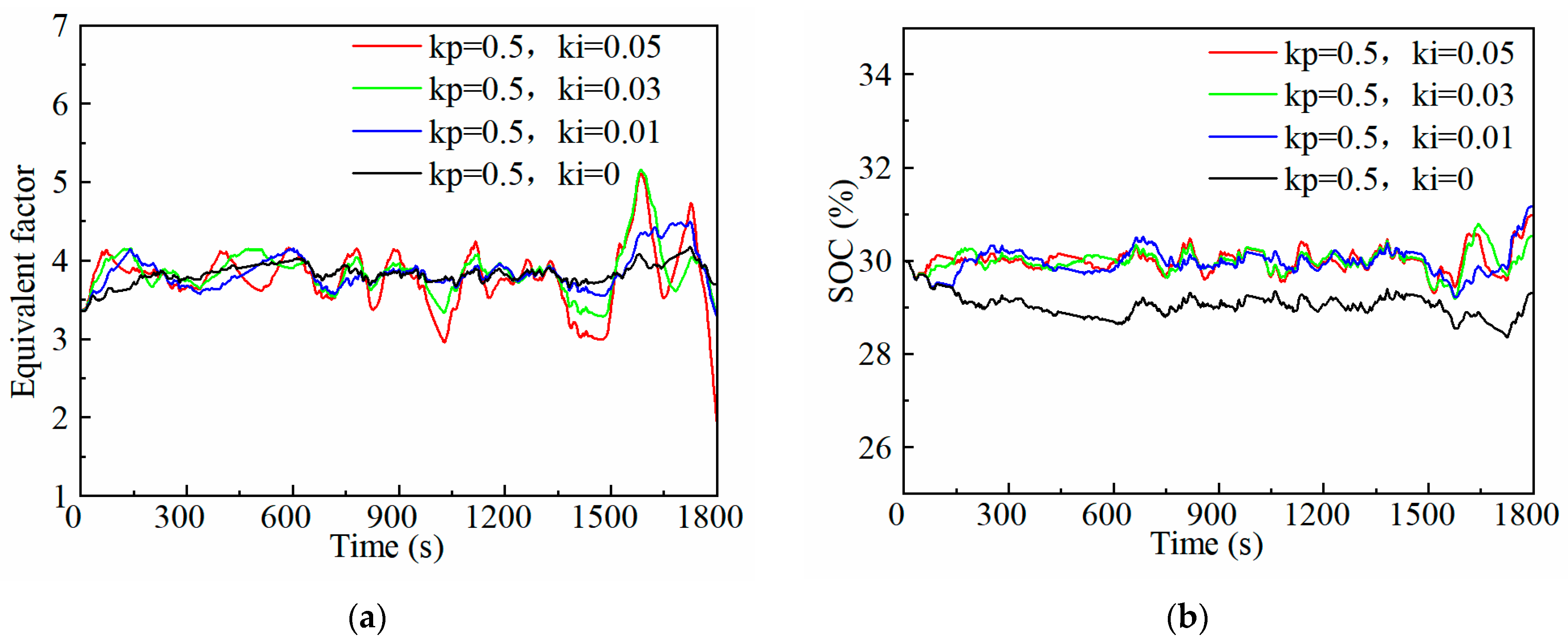
3.2. Adaptive Equivalent Factor Optimization

There are three parameters of the A-ECMS that need to be determined: the initial equivalent factor, the proportional coefficient and the integral coefficient. To analyse the influence of the three parameters, the initial and final SOC of the battery are set to 30%, and the WLTC standard driving cycle is used on the vehicle simulation platform.
When the discharging equivalent factor is 1, the cost of using electric energy is small enough, and the power request of the vehicle is completely satisfied by the battery for the whole cycle. However, when the equivalent factor reaches 6, the strategy tends to use energy that is generated by the range extender rather than batteries, and the range extender works at the maximum power working point in order to charge the battery. Therefore, the range of the equivalent factor is determined to be [1,6]. It should be noted that, as the strategy runs, the initial equivalent factor can be automatically updated quickly through the self-learning method mentioned above. If the trip is long enough, the influence of the initial equivalent factor on the effect of the A-ECMS can be ignored.
Figure 5 shows the adaptation of the equivalent factor and the change in the SOC with a different proportional coefficient K p while the integral coefficient K i is set to zero. When K p grows larger, fluctuations in the equivalent factor are more frequent. In addition, the larger K p is, the smaller the SOC variation range is, and the faster the SOC approaches the target value. Figure 6 shows the result that K p is fixed and K i is variable. With the increase in K i , the equivalent factor changes more rapidly, reaching the fixed equivalent factor of 3.841 faster at the beginning of the cycle, which can maintain the SOC at 30% at the end of the cycle. In addition, the fluctuation of the equivalent factor is more obvious. Additionally, the increase in K i may reduce the SOC steady-state error. However, when K i and K p are too large, the system will be unstable.
To keep the system stable, and to make the final SOC reach the target SOC as close as possible at the end of the trip, the initial equivalent factor is set to 3.4, the proportional coefficient is set to 0.5, and the integral coefficient is set to 0.03.

3.3. Start–Stop Penalty Factor Optimization

Figure 7, Figure 8, Figure 9 and Figure 10 show the effects of the A-ECMS with different start–stop penalty factors. As the penalty factor increases gradually, the start–stop times of the range extender decrease, and the fuel consumption of the A-ECMS with a certain start–stop penalty factor is lower. However, when the penalty factor increases to 0.03, the fuel consumption is greater than 0.01, indicating that a too-high penalty factor will excessively suppress the power change in the range extender, which will reduce the weight of the equivalent fuel consumption term in the Hamiltonian function; this is not conducive to fuel economy.
As shown in Table 2, when comparing the fuel consumption of the A-ECMS with different penalty factors under WLTC, the penalty factor for the start–stop items in the A-ECMS is determined to be 0.02.

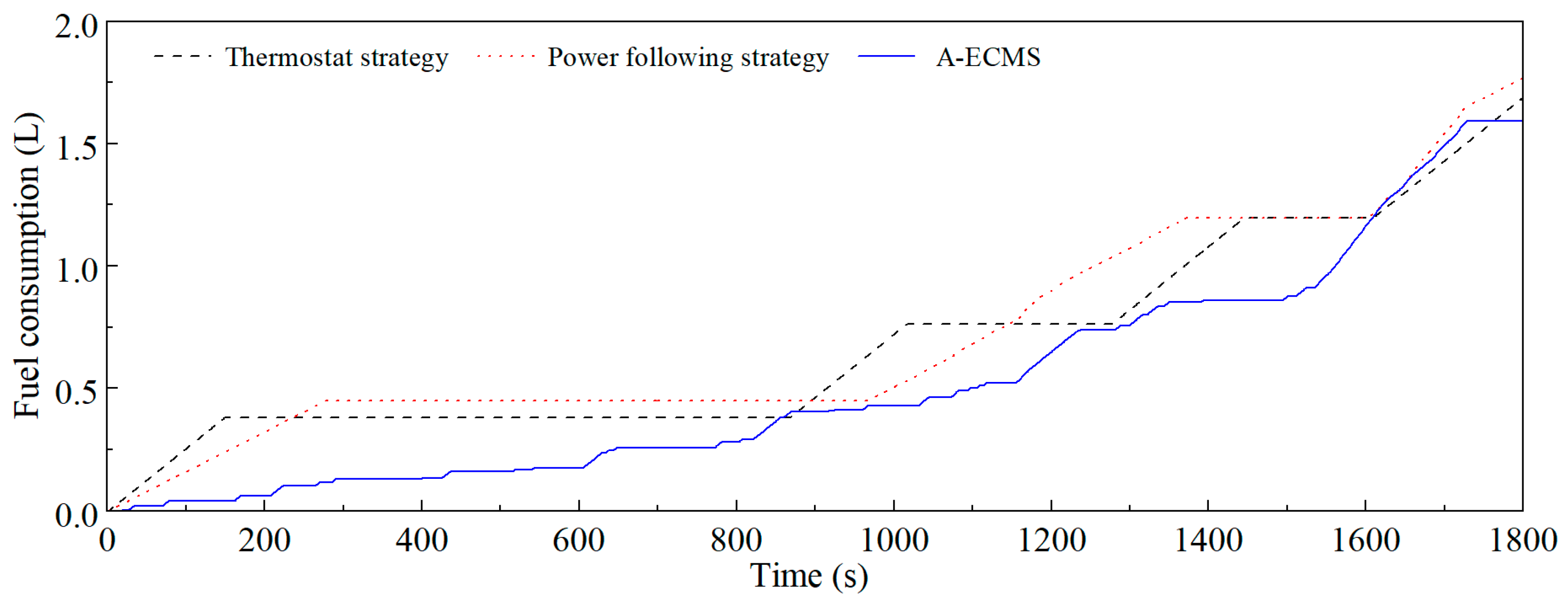
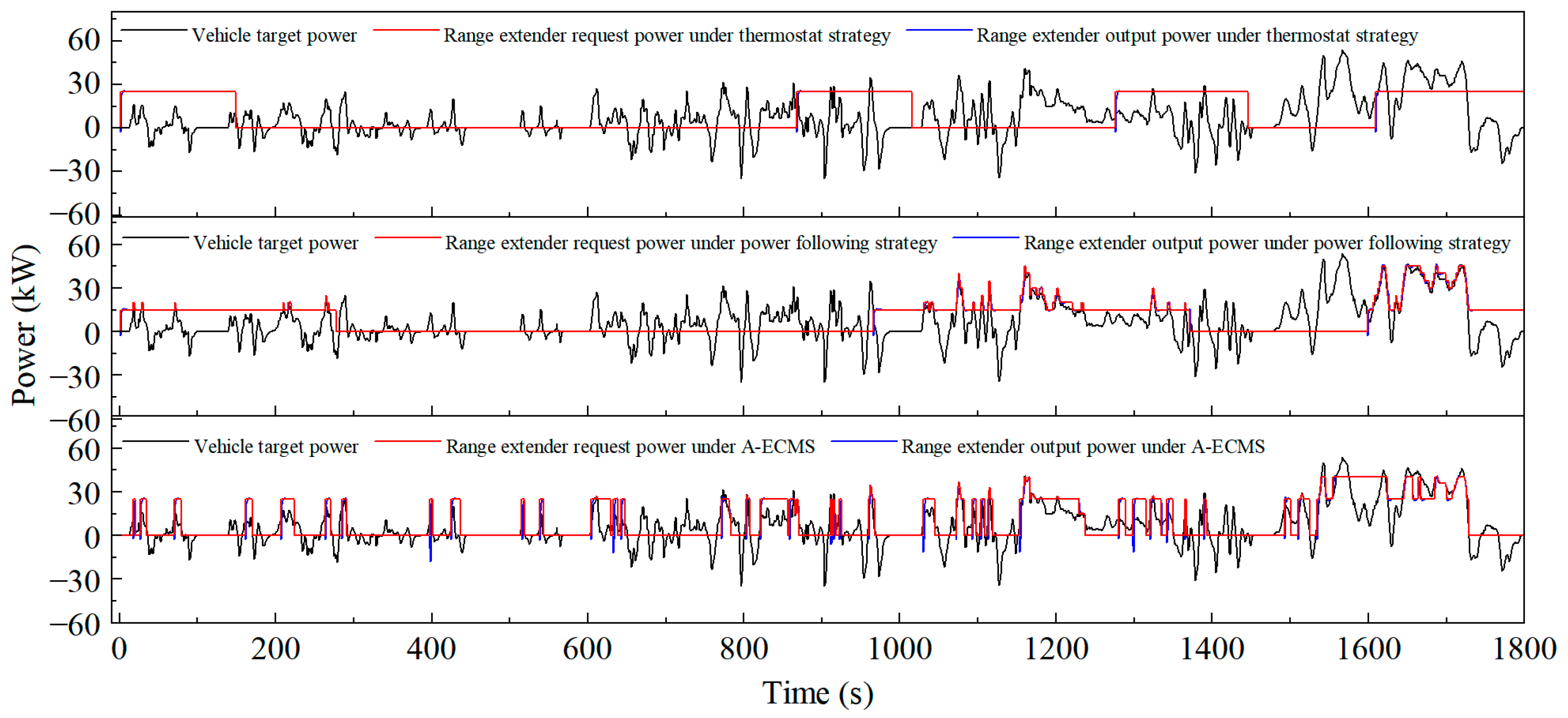
4. A-ECMS Strategy Verification

To verify the performance of the A-ECMS proposed in this paper, the strategy is applied on the vehicle simulation platform, compared with the thermostat strategy and the multi-point power following strategy. The single-point thermostat strategy uses the SOC as the decision-making basis for starting and stopping the range extender. When the SOC is higher than the shutdown threshold, the range extender is turned off, and the power demand is satisfied by the battery. When the SOC is lower than the start-up threshold, the range extender is turned on and it outputs a constant power, the excess power is used for battery charging, and the insufficient power is supplemented by the battery. While the SOC is between the two thresholds, the range extender will be maintained at the previous state. The start–stop control logic of the multi-point power following strategy is the same as that of the thermostat strategy. However, when the range extender is turned on, it works at a series of set working points following the vehicle demand power.
According to the engine efficiency and the ISG motor efficiency, the working points under each vehicle demand power and the minimum specific fuel consumption rates of the range extender are given in Table 3.
For the thermostat strategy, the optimal power generation working point of the range extender is 25 kW, with the lowest specific fuel consumption, which is 262.1 g/kWh. According to engineering experience, the SOC start-up threshold is 30%, and the SOC shutdown threshold is 35%. For the multi-point power following strategy, when the power generation is lower than 15 kW, the minimum specific fuel consumption of the range extender is generally high. Therefore, 5 kW is used as an interval in the range of 15–45 kW.
Since the final SOC may not just reach the target SOC, comprehensive fuel consumption is used to evaluate the fuel economy [23], as shown in Equation (12).
V all = V fuel _ eng + 3600 E bat H LHV ρ fuel η ¯ eng η ¯ isg
where E bat is the battery power consumption, kJ; ρ fuel is the gasoline density, kg/L; V all is the comprehensive fuel consumption, L; and V fuel _ eng is the engine fuel consumption, L. In addition, the battery ampere-hour flux is used to show the effect of the strategy on battery life.
The simulation was run under the WLTC standard driving cycle, and the initial SOC and the target SOC of the battery were both set to 30%. In addition, the ambient temperature was 27 °C, and the wind speed was 0 m/s. From the simulation results, the velocity profiles are the same for the three strategies. This is because, if the battery is not exhausted, the velocity profile has little to do with EMSs, but it does with the drive motor system and the driver model. Figure 11 also shows the vehicle speed following result, and the maximum speed following error does not exceed 0.83 km/h.
Figure 12 shows the fuel consumption changes in the three EMSs during the entire cycle. The thermostat and power following strategies consume fuel in stages, while the A-ECMS consumes fuel during the entire cycle. From the slope of the fuel consumption curve, it can be concluded that the slope of the A-ECMS is relatively the smallest, and the fuel consumption curve of the A-ECMS is below the curve of the thermostat and power following strategy most of the time. At the end of the cycle, the fuel consumption of the thermostat strategy, the power following strategy and the proposed A-ECMS is 1.708 L, 1.768 L and 1.591 L, respectively. The proposed A-ECMS saves about 6.9% of fuel compared to the thermostat strategy, and about 10.0% of fuel compared to the power following strategy. The three strategies will be further compared and analysed from multiple perspectives below.
The target power generation of the range extender determined by the three EMSs is shown in Figure 13. The start–stop state of the range extender under the thermostat strategy has nothing to do with the vehicle power requirement. While under the power following strategy, the power generation of the range extender frequently switches among the set working points with the change in the vehicle power requirement. However, the power generation under the A-ECMS is highly correlated with the vehicle power requirement.
It can be seen from Figure 14 that under the thermostat strategy, the battery is frequently charged and discharged. Once the range extender generates constant power, and the vehicle is in a state of braking energy recovery, the battery will be charged with a large current. The power following strategy can suppress the high current charging and discharging when the range extender is started, but the current is still relatively large when the range extender is turned off. Although the A-ECMS cannot limit the battery working area to a small range like the power following strategy, the range extender will generate power at a high level when the vehicle power demand is large; this can effectively prevent the battery from being discharged at a high current, and the overall charging and discharging performance is the best among the three. The high ampere-hour flux indicates that the battery works more frequently under high-current charging and discharging conditions. On the one hand, the Joule heat will be generated, causing the battery temperature to rise sharply. On the other hand, it will also cause more side reactions inside the battery, thus affecting the terminal voltage and the internal potential of the battery. Both aspects will reduce the service life of the battery [24]. Since the ampere-hour flux of the A-ECMS proposed in this paper is significantly smaller than that of the other two strategies, it is more conducive to prolonging the service life of the battery.
From the perspective of the battery SOC fluctuations shown in Figure 15, the final SOC under the thermostat strategy, the power following strategy, and the A-ECMS are 30.7%, 32.9%, and 30.3%, respectively. The final SOC deviation from the target value under the A-ECMS is only 0.3%. During the trip, since the first two strategies both start the range extender when the SOC is within a certain range, the SOC fluctuates in a large area, which makes the final SOC deviation random. However, due to the adaptive adjustment of the equivalent factor under the A-ECMS, the SOC fluctuates slightly around the target SOC. Therefore, the final SOC under the A-ECMS is most likely to reach the target SOC at the end of the trip. The fluctuation frequency and the amplitude of the SOC can also reflect the working condition of the battery and the ohmic loss of the battery from the side. Via comparison with the other two strategies, it is proven that the proposed A-ECMS can reduce the ohmic loss and protect the battery.
Figure 16, Figure 17 and Figure 18 show the distribution of the working points of the engine and the ISG motor under the three EMSs. Because the ISG motor needs to start the engine occasionally, some of the working points of the ISG motor do not coincide with the working points of the engine. Among the three strategies, the range extender works near the working area with the lowest specific fuel consumption under the thermostat strategy. The distribution of the working points is relatively concentrated under the A-ECMS, and most of the points are distributed in high-efficiency areas. By contrast, the working points for the power following strategy are more scattered.
Table 4 shows the simulation results of energy consumption under the WLTC for the three strategies. The A-ECMS proposed in this paper has a comprehensive fuel consumption of 6.78 L/100 km under the WLTC, which saves 6.2% compared to the thermostat strategy and 3.8% compared to the power following strategy. From the perspective of energy loss, the requested power generation determined by the A-ECMS makes the range extender work in a high-efficiency working area most of time, so that the energy loss of the range extender system is small. At the same time, starting the range extender at an appropriate time during the cycle can avoid charging and discharging the battery with a high current and reduce the ohmic loss of the battery. The above two reasons lead to the least comprehensive fuel consumption of the A-ECMS among the three. Although the thermostat strategy makes the range extender work at the most efficient working points, the battery is in a state of frequent charging and discharging, resulting in a much larger ohmic loss in the battery than the other two strategies. Under the thermostat strategy, the comprehensive fuel consumption is the highest among the three. For the power following strategy, when the range extender is turned on and the requested power of the vehicle is greater than 15 kW, the power generation follows the change of the power demand, and the battery ohmic loss is lower during this period. However, the battery still charges and discharges with a high current for a long time. Further, because the overall efficiency working points of the range extender in the power following strategy are lower than the other two strategies, the comprehensive fuel consumption of it is also higher.
Taking the start–stop frequency of the range extender, the battery charging and discharging performance (ampere-hour flux and SOC fluctuations), and the comprehensive fuel consumption into consideration, the proposed A-ECMS has advantages over the rule-based EMSs.

5. Conclusions

  • The A-ECMS for extended-range electric vehicles, based on the adaptive equivalent factor of SOC feedback and a PI controller, is designed. After the tuning of the PI coefficients, the adaptive equivalent factor can not only make the final SOC reach the target SOC as close as possible at the end of the trip, but also keep the control system stable. From the verification results, the final SOC under the A-ECMS is 30.3%, and the deviation from the target SOC is only 0.3%.
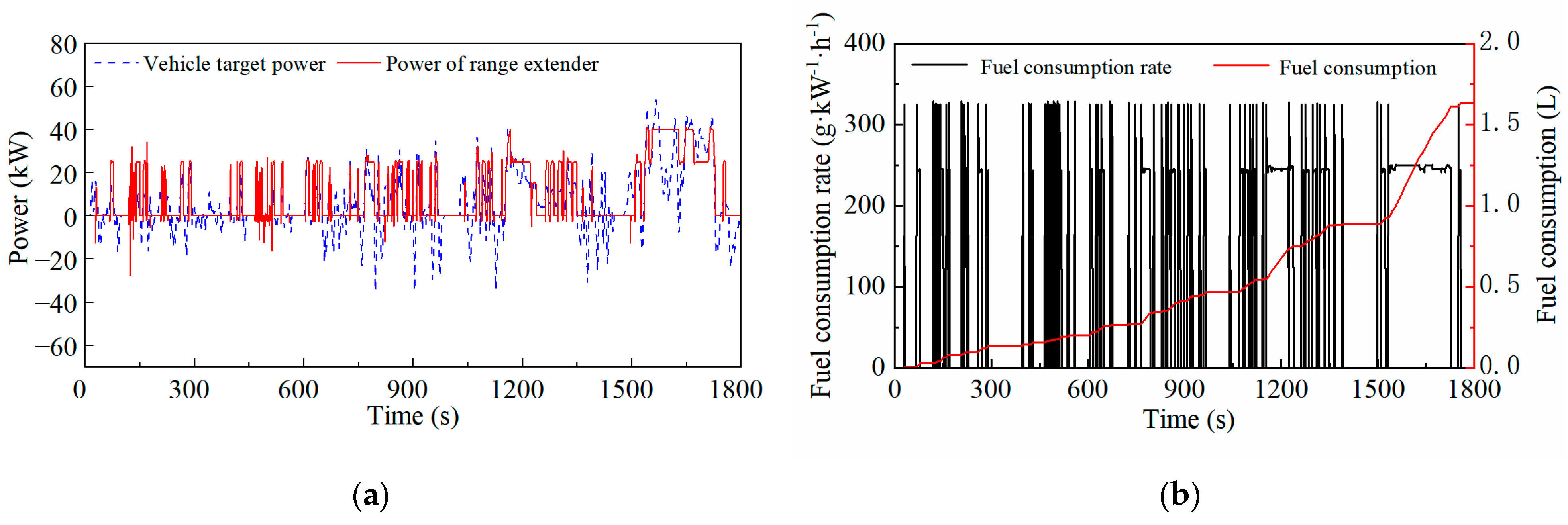
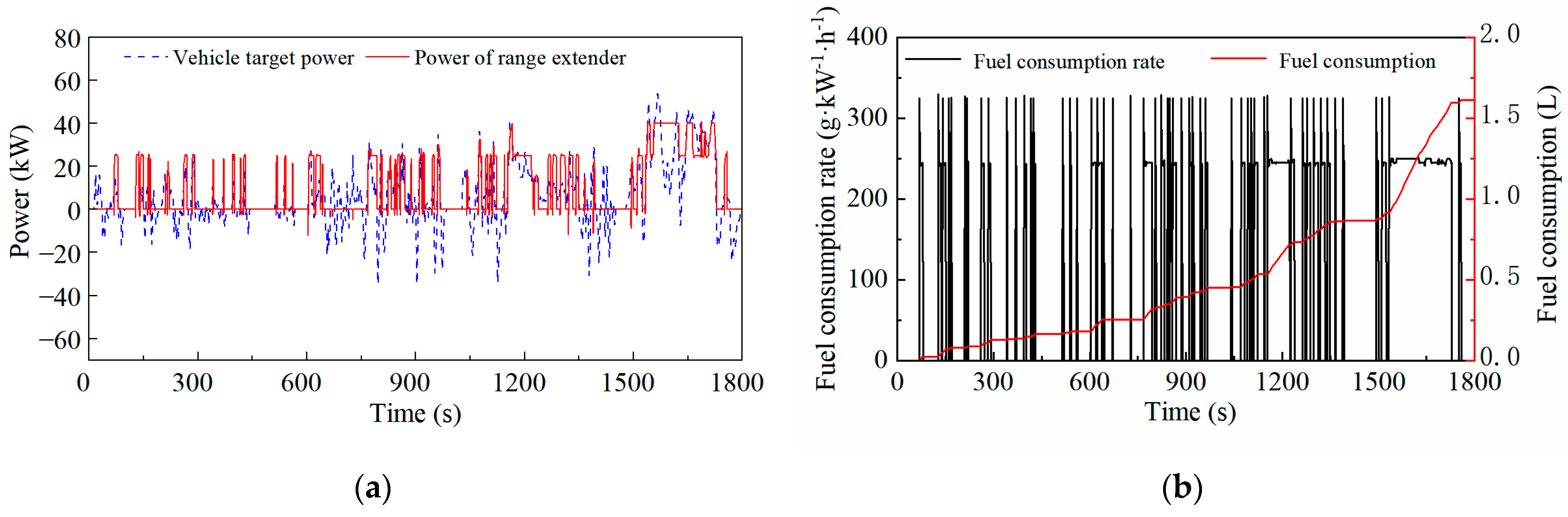
  • Considering the start–stop dynamic characteristics of the range extender, a start–stop penalty term for the range extender is added to the original Hamiltonian function. When a penalty start–stop factor of 0.02 is added, compared with the original A-ECMS, the start–stop times of the range extender are obviously reduced, and the fuel consumption during the entire trip drops from 1.631 L to 1.591 L.
  • Based on the vehicle simulation platform, the proposed A-ECMS is verified under the WLTC. Compared with the thermostat and the power-following strategy, the A-ECMS shows a better fuel economy performance and lower battery ohmic losses. The comprehensive fuel consumption of the A-ECMS is 6.78 L/100 km, which is 6.2% lower than the thermostat strategy and 3.8% lower than the power following strategy. The ampere-hour flux of the battery of the A-ECMS is 10.78 Ah, which is 10.26 Ah lower than the thermostat strategy and 3.69 Ah lower than the power following strategy, which also proves that the A-ECMS is more conducive to prolonging the battery life.

Author Contributions

Conceptualization, D.Y.; Methodology, X.C.; Software, X.C. and J.S.; Supervision, F.W.; Validation, Y.Z., F.Z. and Z.Z.; Writing—original draft, X.L.; Writing—review and editing, D.Y. All authors have read and agreed to the published version of the manuscript.

Funding

This research received no external funding.

Institutional Review Board Statement

Not applicable.

Informed Consent Statement

Not applicable.

Data Availability Statement

Data available on request due to privacy restrictions.

Acknowledgments

Thank you to all reviewers for their suggestions to make this paper better.

Conflicts of Interest

The authors declare no conflict of interest.

Abbreviations

EMSEnergy Management Strategy
A-ECMSAdaptive Equivalent Fuel Consumption Minimization Strategy
ECMSEquivalent Fuel Consumption Minimization Strategy
PMPPontryagin’s Minimum Principle
SOCState Of Charge
PIProportional–Integral
ISGIntegrated Starter Generator
MPCModel Predictive Control
ANN-ECMSArtificial Neural Network Involved Equivalent Fuel Consumption Minimization Strategy
DPDynamic Programming
CSCharge-Sustaining

References

  1. Xue, Q.; Zhang, X.; Teng, T.; Zhang, J.; Feng, Z.; Lv, Q. A Comprehensive Review on Classification, Energy Management Strategy, and Control Algorithm for Hybrid Electric Vehicles. Energies 2020, 13, 5355. [Google Scholar] [CrossRef]
  2. Aslam, S.; Herodotou, H.; Mohsin, S.M.; Javaid, N.; Ashraf, N.; Aslam, S. A Survey on Deep Learning Methods for Power Load and Renewable Energy Forecasting in Smart Microgrids. Renew. Sustain. Energy Rev. 2021, 144, 110992. [Google Scholar] [CrossRef]
  3. Khattak, A.; Bukhsh, R.; Aslam, S.; Yafoz, A.; Alghushairy, O.; Alsini, R. A Hybrid Deep Learning-Based Model for Detection of Electricity Losses Using Big Data in Power Systems. Sustainability 2022, 14, 13627. [Google Scholar] [CrossRef]
  4. Yao, M. Adaptive Real-Time Optimal Control for Energy Management Strategy of Extended Range Electric Vehicle. Energy Convers. Manag. 2021, 234, 113874. [Google Scholar] [CrossRef]
  5. Huang, Y. Model Predictive Control Power Management Strategies for HEVs: A Review. J. Power Sources 2017, 341, 91–106. [Google Scholar] [CrossRef]
  6. Hou, J.; Yao, D.; Wu, F.; Shen, J.; Chao, X. Online Vehicle Velocity Prediction Using an Adaptive Radial Basis Function Neural Network. IEEE Trans. Veh. Technol. 2021, 70, 3113–3122. [Google Scholar] [CrossRef]
  7. Fan, L.; Zhang, Y.; Dou, H.; Zou, R. Design of an Integrated Energy Management Strategy for a Plug-in Hybrid Electric Bus. J. Power Sources 2020, 448, 227391. [Google Scholar] [CrossRef]
  8. Han, L.; Jiao, X.; Zhang, Z. Recurrent Neural Network-Based Adaptive Energy Management Control Strategy of Plug-In Hybrid Electric Vehicles Considering Battery Aging. Energies 2020, 13, 202. [Google Scholar] [CrossRef] [Green Version]
  9. Tian, X.; He, R.; Sun, X.; Cai, Y.; Xu, Y. An ANFIS-Based ECMS for Energy Optimization of Parallel Hybrid Electric Bus. IEEE Trans. Veh. Technol. 2020, 69, 1473–1483. [Google Scholar] [CrossRef]
  10. Zhang, F.; Hu, X.; Langari, R.; Wang, L.; Cui, Y.; Pang, H. Adaptive Energy Management in Automated Hybrid Electric Vehicles with Flexible Torque Request. Energy 2021, 214, 118873. [Google Scholar] [CrossRef]
  11. Zhang, Y.; Chu, L.; Fu, Z.; Xu, N.; Guo, C.; Zhao, D.; Ou, Y.; Xu, L. Energy Management Strategy for Plug-in Hybrid Electric Vehicle Integrated with Vehicle-Environment Cooperation Control. Energy 2020, 197, 117192. [Google Scholar] [CrossRef]
  12. Huang, Y.-H.; Tsai, N.-C. Dual-Objective Energy Management Strategy for HEV. Int. J. Autom. Smart Technol. 2017, 7, 111–118. [Google Scholar]
  13. Rezaei, A.; Burl, J.B.; Zhou, B. Estimation of the ECMS Equivalent Factor Bounds for Hybrid Electric Vehicles. IEEE Trans. Control. Syst. Technol. 2018, 26, 2198–2205. [Google Scholar] [CrossRef]
  14. Xie, S.; Hu, X.; Qi, S.; Lang, K. An Artificial Neural Network-Enhanced Energy Management Strategy for Plug-in Hybrid Electric Vehicles. Energy 2018, 163, 837–848. [Google Scholar] [CrossRef] [Green Version]
  15. Liu, G.; Zhang, J. An Energy Management of Plug-in Hybrid Electric Vehicles Based on Driver Behavior and Road Information. J. Intell. Fuzzy Syst. 2017, 33, 3009–3020. [Google Scholar] [CrossRef]
  16. Shen, Z.; Luo, C.; Dong, X.; Lu, W.; Lv, Y.; Xiong, G.; Wang, F.-Y. Two-Level Energy Control Strategy Based on ADP and A-ECMS for Series Hybrid Electric Vehicles. IEEE Trans. Intell. Transp. Syst. 2022, 23, 13178–13189. [Google Scholar] [CrossRef]
  17. Choi, K.; Byun, J.; Lee, S.; Jang, I.G. Adaptive Equivalent Consumption Minimization Strategy (A-ECMS) for the HEVs with a Near-Optimal Equivalent Factor Considering Driving Conditions. IEEE Trans. Veh. Technol. 2022, 71, 2538–2549. [Google Scholar] [CrossRef]
  18. Zeng, T.; Zhang, C.; Zhang, Y.; Deng, C.; Hao, D.; Zhu, Z.; Ran, H.; Cao, D. Optimization-Oriented Adaptive Equivalent Consumption Minimization Strategy Based on Short-Term Demand Power Prediction for Fuel Cell Hybrid Vehicle. Energy 2021, 227, 120305. [Google Scholar] [CrossRef]
  19. Yang, S.; Wang, J. Self-Adaptive Equivalent Consumption Minimization Strategy for Hybrid Electric Vehicles. IEEE Trans. Veh. Technol. 2021, 70, 189–202. [Google Scholar] [CrossRef]
  20. Deng, T.; Zhao, K.; Yu, H. An Adaptive Equivalent Consumption Minimization Strategy Considering Catalyst Temperature for Plug-in Hybrid Electric Vehicle. Proc. Inst. Mech. Eng. Part D J. Automob. Eng. 2022, 236, 1375–1389. [Google Scholar] [CrossRef]
  21. Wang, Y.; Lou, D.; Xu, N.; Fang, L.; Tan, P. Energy Management and Emission Control for Range Extended Electric Vehicles. Energy 2021, 236, 121370. [Google Scholar] [CrossRef]
  22. Suzuki, S.; Tanaka, K.K.J.; Imagawa, H. Effect of Idling Stop at Traffic Signals on Fuel Consumption of Gasoline Engine Vehicles-Period of Idling Stop and Amount of Saved Fuel. J.-Jpn. Inst. Energy 2004, 83, 64–71. [Google Scholar] [CrossRef] [Green Version]
  23. Chen, X.; Zhong, J.; Sha, F.; Zhong, Z. Research on Innovative Plug-in Hybrid Electric Vehicle Comprehensive Energy Consumption Evaluation Method Based on Statistic Energy Consumption. Sci. Prog. 2021, 104. [Google Scholar] [CrossRef] [PubMed]
  24. Han, X.; Lu, L.; Zheng, Y.; Feng, X.; Li, Z.; Li, J.; Ouyang, M. A Review on the Key Issues of the Lithium Ion Battery Degradation among the Whole Life Cycle. eTransportation 2019, 1, 100005. [Google Scholar] [CrossRef]
Figure 1. The A-ECMS flow chart.
Sustainability 15 04607 g001
Figure 2. Vehicle model powertrain topological diagram.
Sustainability 15 04607 g002
Figure 3. Vehicle simulation calculation signal flow diagram.
Sustainability 15 04607 g003
Figure 4. Comparison of test output value and simulation output value: (a) Output power of the range extender; (b) Battery SOC; (c) Drive motor output torque; (d) Vehicle speed.
Sustainability 15 04607 g004
Figure 5. Adjustment effects of different proportional coefficients of adaptive equivalent factor: (a) Changes in equivalent factor; (b) Changes in SOC.
Sustainability 15 04607 g005
Figure 6. Adjustment effects of different integral coefficients of adaptive equivalent factor: (a) Changes in equivalent factor; (b) Changes in SOC.
Sustainability 15 04607 g006
Figure 7. The effect of the A-ECMS when the penalty factor is 0: (a) Power of range extender; (b) Fuel consumption.
Sustainability 15 04607 g007
Figure 8. The effect of the A-ECMS when the penalty factor is 0.01: (a) Power of range extender; (b) Fuel consumption.
Sustainability 15 04607 g008
Figure 9. The effect of the A-ECMS when the penalty factor is 0.03: (a) Power of range extender; (b) Fuel consumption.
Sustainability 15 04607 g009
Figure 10. The effect of the A-ECMS when the penalty factor is 0.05: (a) Power of range extender; (b) Fuel consumption.
Sustainability 15 04607 g010
Figure 11. Vehicle speed following under the A-ECMS.
Sustainability 15 04607 g011
Figure 12. Fuel consumption of different EMSs under WLTC.
Sustainability 15 04607 g012
Figure 13. Power generation of different EMSs under the WLTC.
Sustainability 15 04607 g013
Figure 14. Battery current of different EMSs under WLTC.
Sustainability 15 04607 g014
Figure 15. SOC fluctuation of different EMSs under the WLTC.
Sustainability 15 04607 g015
Figure 16. Working points of the range extender with thermostat strategy under the WLTC: (a) Engine working points; (b) ISG motor working points.
Sustainability 15 04607 g016
Figure 17. Working points of the range extender with power following strategy under the WLTC: (a) Engine working points; (b) ISG motor working points.
Sustainability 15 04607 g017
Figure 18. Working points of the range extender with the A-ECMS under the WLTC: (a) Engine working points; (b) ISG motor working points.
Sustainability 15 04607 g018
Table 1. Main parameters of extended-range electric vehicles.
ItemsParameterValue
VehicleNo-load mass/kg1740
Wheel radius/m0.33
Windward area/m22.586
Air drag coefficient0.374
Rolling resistance coefficient0.01
Main reducer speed ratio8
Drivetrain efficiency90%
Rotating mass conversion factor1.15
EngineTypeInline four-cylinder gasoline engine
Displacement/L1.5
Rated power/kW45
Maximum power/kW78
Maximum torque/(N·m)140
Maximum speed/rpm5200
ISG motorTypePermanent magnet synchronous motor
Maximum power/kW60
Maximum speed/rpm5000
Maximum torque/(N·m)167
MotorTypePermanent magnet synchronous motor
Maximum power/kW125
Maximum speed/rpm12,000
Maximum torque/(N·m)320
BatteryTypeTernary polymer lithium battery
Capacity/Ah50
Number of series/parallels96/1
Nominal voltage/V345.6
Table 2. Fuel consumption of different start–stop penalty factors.
Start–Stop Penalty FactorsFuel Consumption/L
01.631
0.011.614
0.021.591
0.031.617
0.041.622
0.051.644
Table 3. Working points under each vehicle demand power and the minimum specific fuel consumption of the range extender.
Vehicle Demand Power (kW)Working Point of
Range Extender (kW)
The Minimum Specific Fuel Consumption (g·kW−1·h−1)
<1515277.8
15–2020271.5
20–2525262.1
25–3030269.2
30–3535271.2
35–4040270.8
>4045273.9
Table 4. Comparison of energy consumption results under the WLTC for the three strategies.
Energy Consumption ItemsThermostat
Strategy
Power Following StrategyA-ECMS
Final SOC (%)30.732.330.3
Battery ohmic loss (kJ)751.7454.8217.4
Ampere-hour flux (Ah)21.0414.47710.78
Fuel consumption (L)1.7081.7681.591
Comprehensive fuel consumption (L)1.6791.6391.574
Comprehensive fuel consumption (L/100 km)7.237.056.78
Disclaimer/Publisher’s Note: The statements, opinions and data contained in all publications are solely those of the individual author(s) and contributor(s) and not of MDPI and/or the editor(s). MDPI and/or the editor(s) disclaim responsibility for any injury to people or property resulting from any ideas, methods, instructions or products referred to in the content.

