
Design and Research of Heat Storage Enhancement by Innovative Wave Fin in a Hot Water–Oil-Displacement System


1
School of Human Settlements and Civil Engineering, Xi’an Jiaotong University, Xi’an 710049, China
2
Management Headquarters of Water Injection Project, Yanchang Oil Field Co., Ltd., Yan’an 716000, China
*
Authors to whom correspondence should be addressed.
Sustainability 2023, 15(22), 15785; https://doi.org/10.3390/su152215785
Submission received: 7 October 2023
/
Revised: 1 November 2023
/
Accepted: 8 November 2023
/
Published: 9 November 2023
(This article belongs to the Topic Thermal Energy Transfer and Storage)
Abstract
:Energy storage technology provides a new direction for the utilization of renewable and sustainability energy. The objective of this study is to introduce a novel, wavy, longitudinal fin design, which aims to improve heat transfer in the melting process of a Latent Heat Thermal Energy Storage (LHTES) unit. The main goal is to mitigate the negative effects caused by the refractory zone at the end of the melting phase. A two-dimensional numerical model of LHTES unit is established by using the enthalpy porosity method and verified by experimental data. Through the quantitative comparison between the traditional rectangular fin and the innovative wave fin, the influence of wave fin on the heat transfer mechanism in the heat storage process is revealed. The results show that the average heat storage rate of five and six wave fins is 3.70% and 12.98% higher than that of conventional rectangular fins, respectively, and the average temperature response of six wave fins is 17.78% higher than that of conventional rectangular fins. The addition of the wave fin weakens the negative effect of the refractory zone, but prolongs the heating time of the initial melting point.
1. Introduction
To facilitate the transition to low-carbon energy, the European Union has established an objective of achieving a minimum of a 40% reduction in greenhouse gas emissions by 2030. However, the energy consumption in Europe is predominantly attributed to building heating and cooling, which accounts for approximately 50% of the total energy usage [1,2], and the utilization of energy always results in the wasteful consumption of heat energy. The efficient utilization of new energy sources and energy transformation [3] are currently important topics. The energy storage technology development is crucial for the utilization of renewable energy sources, which can store the heat generated during energy utilization and integrate renewable energy into the energy system [4,5]. This integration enhances the flexibility in utilizing energy and boosts the energy system’s overall efficiency [6].
Thermal energy storage technology [7] involves changing the storage medium temperature through heating or cooling, and releasing its internal thermal energy when needed for building heating/cooling and industrial operations. Latent heat storage utilizes phase change materials (PCM) as the heat storage medium [8]. This technology has gained attention in recent years because of its advantages of high latent heat capacity, temperature stability, and minimal volume change [9,10]. The widespread implementation of PCM is hindered by their limited capacity for heat transfer due to their low thermal conductivity [11,12].
Extensive research has been undertaken with the aim of enhancing the thermal efficiency of LHTES systems [13,14]. These studies have focused on various approaches, including the use of metal fins or metal foam [15,16], dispersing nanoparticles in PCM to improve overall heat exchange efficiency [17,18], and packaging PCM to improve heat transfer uniformity [19,20]. Among these approaches, enhancing heat transfer performance through metal fins is advantageous due to its simplicity and efficiency [21]. For example, Kumar and Verma [22] undertook both experimental/numerical investigations into the melting characteristics of lauric acid, which is a PCM commonly utilized in LHTES systems. They investigated the effect of different inner tube eccentricity and fin angles on melting properties and found that a bottom annular fin angle of 60° reduced the storage time by 18.7%, while increasing the inner tube eccentricity increased the heat charging rate by 21%. Li et al. [23] designed experimental structures of shell-and-tube LHTES units with different fin structures and nano-additive content. Their addition of nanoparticles had a negative influence on instantaneous storage and overall melting rate. They also found that longitudinal fins had the best effect on the pre-melting process compared to annular and spiral fins, reducing the storage time by 16%. Zhang et al. [24] used an innovative spiral fin for enhanced heat transfer in LHTES systems and studied its effect compared to traditional rectangular fins through numerical simulation of the charging process. The whole charging time of the four-helical fin LHTES was significantly decreased by 31% compared to conventional fins, and the temperature of inlet fluid had a significant effect on the charging process. Huang et al. [25] used LHTES devices for heat storage and designed palm-leaf-shaped bionic fins to improve waste heat recovery efficiency in cooling systems. Their research demonstrated that the palm-leaf bionic fins shortened the charging and discharging time of LHTES by 21.0% and 38.2%. Furthermore, economic analysis showed that the minimum payback period of the LHTES device was only 2 years. Hosseinzadeh et al. [26] comprehensively studied the influence of new fins and mixed nanoparticles (MoS2-Fe3O4) on the discharging process of triple-tube LHTES units, and verified their numerical calculation model through experimental data. Their results showed that under the optimization methods, the solidification performance of mixed nanoparticles and new fins was significantly enhanced, with radiation parameters contributing to 74.58% of the whole discharging time. Huang et al. [27] proposed a comprehensive enhanced heat storage process for triple-tube LHTES units using inner tube eccentricity and fin offset. They studied the specific effects of these parameters on melting time through the response surface method and found that under optimal conditions, fin offset, and the inner tube eccentricity could significantly reduce the unit charging time by 23.87% without changing the volume of the inner PCM. Modi et al. [28] researched the effect of different fin heights and aperture-perforated fins on the charging/discharging process of LHTES units. They also studied the effect of different fin angles on the temperature rise rate in the heat-charging process. Their results showed that the optimum fin height was 65% of the unit, and fin height had little effect on the heat-discharging process. The melting time of 4 mm and 8 mm perforated fins was reduced by 12.65% and 3.16%. Ma et al. [29] designed a novel circular fin to enhance the heat storage performance of Li2CO3-K2CO3-Na2CO3 (32-35-33 wt%) in LHTES systems. They conducted numerical studies on exothermic performance and the exergy efficiency of different fin structures. The solidification time of heat transfer fluid (HTF) could be reduced by 38.72%. The HTF specific exergy decreased rapidly during the heat discharging process, and the study recommended specific parameters for the HTF inlet speed and temperature. While these studies have made significant contributions to fin design and parameter optimization [30,31], the use of fins reduces the PCM volume in LHTES systems. Therefore, it is important to study how to minimize the impact of fins on PCM volume and maximize the heat charging/discharging performance of the system.
In this study, an innovative type of wavy fin is designed to enhance the heat-charging performance of a double-tube LHTES unit. The numerical comparison between different numbers of wavy fins and traditional rectangular fins is conducted and verified by experimental data. The research mainly focuses on the liquid/temperature distribution evolution, liquid phase rate, heat absorption, heat absorption rate, and temperature response of the fin structure in the heat-charging process of the LHTES unit. This research has demonstrated that the implementation of a wavy fin significantly enhances the heat transfer capabilities of the LHTES unit.
2. Model Description
2.1. Physical Model
Figure 1 illustrates a phase-change thermal storage system coupled with an offshore platform for the petroleum industry. The key component of this system is the phase-change storage system. In this study, we have selected a unit from the phase-change storage system, as depicted in Figure 2a. This unit is a double-tube LHTES unit, with both inner/outer tube walls made of copper and a thickness of 1 mm. The HTF flows through the PCM in the inner/outer tubes, and longitudinal fins are used in the unit to enhance heat transfer. We have investigated and designed five different fin structures, including the traditional rectangular fin and four wavy longitudinal fin structures, as shown in Figure 2(b1–b5). To facilitate further research, we have simplified the research object to the cross-section. The geometric parameters of the LHTES units are presented in Table 1, while the PCM physical parameters are provided in Table 2. The initial PCM used is Paraffin RT50, and RT82 Paraffin is used for verification.
2.2. Mathematical Model
The following assumptions are made first [34]:
- (1)
- Liquid PCM exhibits incompressible Newtonian laminar flow;
- (2)
- The Boussinesq hypothesis is employed to describe the generation of natural convection;
- (3)
- The PCM thermophysical properties are independent of temperature;
- (4)
- There is no heat exchange between the LHTES unit and the external environment.
Equation (1) is the continuity equation, Equations (2) and (3) are the momentum equations, and Equation (4) is the energy equation [35]:
Expression for Boussinesq hypothesis:
where Amush = 105 refers to the velocity momentum in the paste region [36]. is a decimal that prevents the equation denominator from being 0. fm is the PCM liquid fraction:
Given the amount of heat absorbed:
2.3. Initial and Boundary Conditions
Initial condition:
Boundary conditions:
The non-slip-coupled thermal transfer conditions between fins/PCM are:
where Ω accounts for the contact thermal transfer interface between fins/PCM.
3. Numerical Method and Model Validation
3.1. Meshing and Numerical Processes
In this study, the phase transformation process is calculated [39], and the numerical solution is performed based on the solidification/melting model in Ansys Fluent 2021. The coupling calculation of pressure-velocity is achieved using the SIMPLE algorithm. The pressure correction is implemented using the PRESTO! method. The residuals for the continuity equation, momentum equation, and energy equation are set to 10−5, 10−5, and 10−8. Grid division is carried out through IECM, and the main fin structures are obtained as shown in Figure 3. Grid diagrams of the traditional rectangular fin and six wavy fin structures are provided. The grid is divided using an unstructured mesh, with quadrilaterals as the main elements and triangles as the auxiliary elements. The mesh is refined around the fin to ensure accuracy.
3.2. Grid Independence and Time Step Study
The mesh independence and time step of the Fin-1 structure are verified. Three different mesh numbers (58,521, 10,478, 20,347) and three different time steps (0.25 s, 0.5 s, 0.1 s) were used. The effects of different mesh numbers and time steps on the liquid phase rate in the melting process are shown in Figure 4a and Figure 4b, respectively. They show that the mesh number has little effect on the liquid phase rate, while a significant deviation is caused by the 0.1 s time step. A good consistency is achieved when the time step is reduced. Therefore, after careful consideration, a mesh number of 10,478 and a time step of 0.05 s were selected for subsequent calculations.
3.3. Model Validation
The effectiveness of the numerical process is validated by the correlational study of Abidi et al. [40] and was used for model verification. The boundary/initial conditions of the numerical process are adjusted to be consistent with the experiment: the initial PCM temperature of the paper is 30 °C, and the HTF heating temperature is 90 °C. The PCM used is Paraffin RT82, as shown in Table 2. The relationship between experimental and simulated dimensionless temperatures () in the melting process is compared. The independent variable of the horizontal axis is dimensionless Fourier number (F0). The comparison between experiment and numerical simulation is shown in Figure 5. The results show that the maximum difference of dimensionless temperature between experimental and numerical simulation is 3.69%. These results sufficiently demonstrate the accuracy of the numerical model established in this study.
4. Results and Discussion
4.1. Comparison of Melting Process
In this section, we investigate the influence of different fin structures on the LHTES charging process. We examine the liquid phase fraction and temperature distributions of Fin-1~Fin-5 at different time, as shown in Figure 6 and Figure 7. Figure 6 illustrates the specific effect of the rectangular Fin-1 on the heat charging process. At t = 60 s, the melted PCM is primarily concentrated near the inner tube wall and fin, with a higher melted PCM area at the fin root compared to the fin tip. This is attributed to the rapid temperature rise of the tube wall and fin caused by the hot fluid during the melting stage, resulting in a higher temperature rise rate at the fin root than at the fin tip. The temperature distribution in Figure 7 confirms that the temperature at the root of the fin is higher than that at the tip. Heat is conducted through the temperature difference between the tube wall, fin, and PCM. At t = 300 s, a significant difference is observed between the upper and lower parts of the model because of the charging process and gradual enhancement of natural convection. The thermal buoyancy generated by natural convection leads to a slightly stronger melting effect in the upper half of the model compared to the lower half. At t = 600 s and 900 s, it is evident that the unmelted PCM area in the lower part is much larger than that in upper. Figure 7 reveals that the lower part of Fin-1 structure has a lower temperature level than the upper part at these times, resulting in the gradual formation of a left and right symmetric refractory zone during the melting process. The influence of the refractory zone becomes particularly significant in the final stages of melting. At t = 1800 s and 3000 s, the upper part of the Fin-1 structure has already achieved complete melting, while the refractory zone in the lower part delays the completion of melting.
By comparing different wavy fin structures, we find that the melting effect of the three wavy fins in the Fin-2 structure on the PCM is lower than that of the rectangular Fin-1. At t = 1800 s and 3000 s, it is evident that the unmelted PCM area in the model is larger than that in Fin-1. Due to the structural characteristics of the wavy fins, the symmetry pattern of the left and right sides during the heat-charging process is disrupted, and, overall, the internal temperature level of the Fin-2 structure at the end of charging is lower than Fin-1. Therefore, the wavy fin number has a certain effect on the heat charging process of the LHTES unit. Next, we compare the Fin-3 structure with the Fin-1 structure, with the only difference being the fin structure. Due to the irregularity of the wavy fin, at t = 600 s and 900 s, the interior of this unit is divided into four different melting structures. However, the overall melting process is similar to that of Fin-1. At t = 1800 s and 3000 s, it can be observed that the left and right symmetric structure of the refractory zone changes at 3000 s. The unmelted PCM area on the left is smaller than that on the right, and the overall area of the refractory zone is larger than that of the Fin-1 structure at this time. This is because the area of the refractory zone changes from equal division to unequal division, and the larger refractory zone area further prolongs the melting time. Therefore, replacing the traditional rectangular fins with wavy fins does not significantly enhance the melting properties when the fin number remains the same.
Furthermore, we further study the Fin-4 structure with five wavy fins and the Fin-5 structure with six wavy fins. At t = 600 s and 900 s, the Fin-4 structure divides the melting zone into five sections, while the Fin-5 structure divides it into six sections. By comparing temperature distribution, it is evident that the overall internal temperature level is higher than that of the Fin-1 structure. Compared to the final stages of melting (t = 1800 s and 3000 s), the Fin-4 structure is like Fin-2 and Fin-3 at t = 1800 s, with the refractory zone divided into two irregular zones by the new wavy fin, but with a smaller area. At t = 1800 s, the refractory zone of Fin-5 is mainly divided into three parts with different areas. At t = 3000 s, it is evident that the refractory zone area of Fin-4 is much smaller than Fin-1, and the Fin-5 structure has essentially completed melting by this time. Comparing the temperature gradient, the internal temperature of the wavy fin is not symmetrical like that of the Fin-1 structure, but the overall temperature level is higher.
4.2. Study of Liquid Phase Rate Parameters
Next, we investigate the specific influence of different fin structures on the heat-charging performance of this LHTES unit, as depicted in Figure 8. We compare the impact of these structures on the liquid–phase fraction, average temperature of PCM, melting rate, and melting time.
Figure 8a illustrates the change in the liquid fraction of this unit. It is evident that the Fin-1 and Fin-5 structures exhibit the fastest increase in liquid phase fraction during the pre-melting phase (t < 500 s). Conversely, the other three structures with wavy fins demonstrate a slower evolution of the liquid fraction. This is due to the increased overall length of the fin due to the application of wavy fins, resulting in a longer heating time of the fin by the hot fluid during the early melting period. Consequently, the melting influence of the fin on the PCM is diminished. The Fin-5 structure mitigates this effect by increasing the number of wavy fins, thereby improving the overall melting performance. Notably, the Fin-2 structure exhibits the longest charging time, followed by the Fin-3. Figure 8d provides a comparison of the melting times, revealing that the charging time of Fin-2 and Fin-3 increased by 31.30% and 13.04%, compared to Fin-1. Conversely, the heat storage time of the Fin-4 and Fin-5 structures is 4.31% and 11.45% shorter than that of the Fin-1 structure, respectively. Therefore, the use of wavy fins can mitigate the negative impact of the refractory zone at the end of the heat charging process by increasing fin numbers, resulting in improved melting performance.
Figure 8b presents a comparison of the PCM average temperature. Temperature change of the Fin-4 structure closely resembles that of the PCM with Fin-1. Additionally, the Fin-5 structure exhibits superior melting performance, due to a higher overall temperature of the PCM compared to Fin-1. Figure 8c displays the melting rates. The Fin-2 structure exhibits the lowest melting rate before 1000 s due to the smaller number of wavy fins, which significantly reduces the melting effect on the PCM. Conversely, the Fin-5 structure demonstrates the highest heat charging rate during the early melting stage. But after t > 1000 s, the melting rate decreases continuously until it approaches 0. This is attributed to the substantial reduction in the volume of unmelted PCM, the weakening of natural convection over time, and the dominance of heat conduction as the main melting process. The charging rate of the Fin-2 structure fluctuates less throughout the overall melting process and remains low, resulting in the longest melting time. During the early storage process, by significantly increasing the melting rate, the Fin-5 structure achieves a substantial reduction in the overall charging time. Specifically, compared to the Fin-2 structure, the Fin-5 structure experiences a 32.56% reduction in charging time after the addition of three wavy fins. However, due to the model’s inability to account for the effect of the refractory zone at the end of the heat storage process, the charging rate of all structures decreases over time, ultimately reaching its lowest point.
4.3. Study on Heat Storage Parameters
The changes in heat storage and heat storage rate during the heat-charging process are presented in Figure 9. Table 3 provides a comparison of the total heat absorption for each part during a heat-charging cycle.
Figure 9a illustrates the change in sensible absorption of heat energy. The Fin-5 structure, which exhibits the fastest melting rate, also demonstrates the fastest change in sensible heat energy absorption. The absorption of latent heat energy is closely linked to the liquid phase rate. However, because of the varying volume of fins occupying the unit, there are slight differences in the total latent heat energy at the completion of melting. Nonetheless, the overall trend is similar to the liquid phase rate depicted in Figure 9a. The changing trend of total thermal absorption is shown in Figure 9c. During the pre-melting stage, the fastest change in total heat absorption is observed in the Fin-1 and Fin-5 structures. However, the melting rate of the Fin-1 structure decreases due to the charging process, and the influence of the refractory zone in the final stage becomes evident. After t > 1000 s, the change in total heat absorption is lower than that of the Fin-5 structure and is gradually surpassed by the Fin-4 structure. Table 3 presents the total heat absorption corresponding to each structure during the charging cycle. Because of the fin’s small size, the difference in total latent heat energy is negligible. Compared to the Fin-1 structure, the whole latent heat absorption of the Fin-2 structure decreased by 0.689%, while the total latent heat absorption of the Fin-5 structure increased by 0.159%. The overall difference was not significant. The corresponding total thermal absorption of the Fin-2 structure increased by 0.107% compared to the Fin-1 structure, while the Fin-5 structure decreased by 0.15% compared to the Fin-1 structure. Figure 9d demonstrates that the initial instantaneous heat storage rate is the highest for all five structures, followed by a rapid decrease and stabilization. Among them, the instantaneous rate of heat storage of the Fin-1 and Fin-5 structures is slightly higher than the other three structures. Comparing the mean heat storage rate in Figure 9e, the average heat storage rate of the Fin-2 and Fin-3 structures decreased by 23.83% and 11.91%, respectively, compared to the Fin-1 structure. Conversely, the average heat storage rate of the Fin-4 and Fin-5 structures increased by 3.70% and 12.98%, respectively.
4.4. Study of Temperature Response
The and (average temperature response rate) are introduced to neat study [41]:
where and represent the temperature at and , respectively, and and is the time at any moment and the whole melting time.
The comparison between the and is presented in Figure 10. From Figure 10a, it can be observed that rapidly increases to its peak at the initial melting stage and gradually declines thereafter. The Fin-5 structure consistently exhibits the highest instantaneous temperature response throughout the entire melting process, while the Fin-3 structure demonstrates the lowest instantaneous temperature response, which is determined by the corresponding melting performance of the different structures. Comparing the average temperature response among different structures in Figure 10b, of the Fin-2 and Fin-3 structures decreases by 25.96% and 12.38%, respectively, compared to that of the Fin-1 structure. Conversely, compared to that of the Fin-1 structure, the average heat storage rate of the Fin-4 and Fin-5 structures increases by 4.16% and 17.78%, respectively. This further confirms the critical role of the number of fins in the utilization of new wavy fins, as the temperature response increases with an increase in fin numbers.
5. Conclusions
Latent Heat Thermal Energy Storage technology provides a path for the sustainable utilization of thermal energy. In this paper, a new wave type longitudinal fin is proposed to enhance heat transfer in its phase transition process. A two-dimensional numerical model of the LHTES unit is established, and the effect of the novel wavy fin on the heat transfer mechanism is revealed. A quantitative comparison is made with conventional rectangular fins. The main results are as follows:
- (1)
- Compared with the traditional rectangular fin, the wavy fin needs a longer heating time during the melting process, but it mitigates the negative effects caused by the refractory zone at the end of the melting phase;
- (2)
- The wavy fin number has a significant effect on its performance. The charging time of six wavy fins is 11.45% lower than rectangular fins, and the charging time is 32.56% lower than three wavy fins;
- (3)
- The number of wavy fins has a certain effect on the PCM volume in the LHTES unit, but the heat absorption change within a melting cycle is almost negligible. The average heat storage rate of five and six wavy fins is 3.70% and 12.98% higher than that of conventional rectangular fins, respectively;
- (4)
- The instantaneous temperature response of the LHTES unit corresponding to different fin structures all increased rapidly to the highest point at the beginning and gradually decreased. The average temperature response of six wavy fins is 17.78% higher than that of conventional rectangular fins.
- (5)
- This study only considers the number of three to six wavy fins, and further expansion of the number of fins is also worth studying. At the same time, the research on the solidification process of the phase change heat storage unit with the novel fin is also worth exploring.
Author Contributions
Conceptualization, T.N. and X.H.; methodology, X.H.; software, X.Y.; validation, J.S., T.N. and X.Y.; formal analysis, X.Y.; investigation, X. Huang; resources, J.S. and X.Y.; data curation, J.S.; writing—original draft preparation, X.H. and X.Y.; writing—review and editing, T.N. and J.S.; visualization, X.H.; supervision, J.S.; project administration, X.Y.; funding acquisition, J.S. All authors have read and agreed to the published version of the manuscript.
Funding
This work was supported by National Natural Science Foundation of China (12072256).
Data Availability Statement
No data were used in this study.
Conflicts of Interest
Author Tao Ning was employed by the company Yanchang Oil Field Co., Ltd. The remaining authors declare that the research was conducted in the absence of any commercial or financial relationships that could be construed as a potential conflict of interest.
Nomenclature
| Abbreviation | |
| LHTES | Latent Heat Thermal Energy Storage |
| PCM | Phase Change Material |
| HTF | heat transfer fluid |
| Symbols | |
| R1 | Isobaric specific heat |
| R2 | Thermal conductivity |
| Li | Longitudinal height of fins |
| di | Transverse width of the fin |
| k | Thermal conductivity |
| cp | Isobaric specific heat |
| Tm | Melting temperature |
| Ts | Solidus temperature |
| Tl | Liquidus temperature |
| Amush | Velocity momentum in the paste region |
| A decimal that prevents the equation denominator from being 0 | |
| fm | PCM liquid fraction |
| Melting rate | |
| h | Total enthalpy |
| Qs | Sensible heat absorption |
| Ql | Latent heat absorption |
| Q | Total heat absorption |
| Instantaneous rate of thermal absorption | |
| Average rate of thermal absorption | |
| Instantaneous temperature response rate | |
| Average temperature response rate | |
| Time at any moment | |
| Whole melting time | |
| Greek symbols | |
| μ | Dynamic viscosity |
| ρ | Density |
| λ | Latent heat of fusion |
| β | Volumetric coefficient of thermal expansion |
| Ω | Contact thermal transfer interface |
| Subscripts | |
| fin | Area of fins |
| pcm | Area of PCM |
| i | Initial |
| w | The wall |
References
- European Association for Storage of Energy. Thermal Storage Position Paper. 2017. Available online: http://ease-storage.eu/wp-content/uploads/2017/07/2017.07.10_EASE-Thermal-Storage-Position-Paper__for-distribution.pdf (accessed on 30 April 2020).
- He, Q.; Tapia, F.; Reith, A. Quantifying the influence of nature-based solutions on building cooling and heating energy demand: A climate specific review. Renew. Sustain. Energy Rev. 2023, 186, 113660. [Google Scholar] [CrossRef]
- Lupoae, O.-D.; Radu, R.I.; Capatina, A.; Isai, V.M.; Bărbuță-Mișu, N. Exploring Precursors of Renewable Energy Portfolio Diversification Using TPB. Energies 2023, 16, 6714. [Google Scholar] [CrossRef]
- Rahman, M.M.; Oni, A.O.; Gemechu, E.; Kumar, A. Assessment of energy storage technologies: A review. Energy Convers. Manag. 2020, 223, 113295. [Google Scholar] [CrossRef]
- Rui, S.; Guo, Z.; Zhou, W. Promoting Sustainable Marine Development: Geotechnical Engineering Problems and Environmental Guarantee Technology in Marine Space, Energy, and Resource Development. Sustainability 2023, 15, 14424. [Google Scholar] [CrossRef]
- Güneş, H.; Simba, H.M.A.; Karadağ, H.; Şit, M. Global Energy Transformation and the Impacts of Systematic Energy Change Policy on Climate Change Mitigation. Sustainability 2023, 15, 14298. [Google Scholar] [CrossRef]
- Pathak, S.K.; Tazmeen, T.; Chopra, K.; Tyagi, V.V.; Anand, S.; Abdulateef, A.M.; Pandey, A.K. Sustainable Energy Progress via Integration of Thermal Energy Storage and Other Performance Enhancement Strategies in FPCs: A Synergistic Review. Sustainability 2023, 15, 13749. [Google Scholar] [CrossRef]
- Guo, Z.; Zhou, W.; Liu, S.; Kang, Z.; Tan, R. Effects of Geometric Parameters and Heat-Transfer Fluid Injection Direction on Enhanced Phase-Change Energy Storage in Vertical Shell-and-Tube System. Sustainability 2023, 15, 13062. [Google Scholar] [CrossRef]
- Miao, A.; Yuan, Y.; Huang, Y.; Wu, H.; Feng, C. Stochastic Optimization Model of Capacity Configuration for Integrated Energy Production System Considering Source-Load Uncertainty. Sustainability 2023, 15, 14247. [Google Scholar] [CrossRef]
- Yin, Z.; Zheng, J.; Kim, H.; Seo, Y.; Linga, P. Hydrates for cold energy storage and transport: A review. Adv. Appl. Energy 2021, 2, 100022. [Google Scholar] [CrossRef]
- Huang, X.; Li, F.; Li, Y.; Meng, X.; Yang, X.; Sundén, B. Optimization of melting performance of a heat storage tank under rotation conditions: Based on taguchi design and response surface method. Energy 2023, 271, 127100. [Google Scholar] [CrossRef]
- Cui, P.; Yang, W.; Zhang, W.; Zhu, K.; Spitler, J.D.; Yu, M. Advances in ground heat exchangers for space heating and cooling: Review and perspectives. Energy Built Environ. 2024, 5, 255–269. [Google Scholar] [CrossRef]
- Zhang, C.; Huang, Y.; Chen, Y. Bionic study on latent heat thermal storage. Renew. Sustain. Energy Rev. 2023, 183, 113529. [Google Scholar] [CrossRef]
- Shank, K.; Tiari, S. A Review on Active Heat Transfer Enhancement Techniques within Latent Heat Thermal Energy Storage Systems. Energies 2023, 16, 4165. [Google Scholar] [CrossRef]
- Cui, W.; Si, T.; Li, X.; Li, X.; Lu, L.; Ma, T.; Wang, Q. Heat transfer enhancement of phase change materials embedded with metal foam for thermal energy storage: A review. Renew. Sustain. Energy Rev. 2022, 169, 112912. [Google Scholar] [CrossRef]
- Najim, F.T.; Bahlekeh, A.; Mohammed, H.I.; Dulaimi, A.; Abed, A.M.; Ibrahem, R.K.; Al-Qrimli, F.A.; Mahmoud, M.Z.; Awrejcewicz, J.; Pawłowski, W. Evaluation of Melting Mechanism and Natural Convection Effect in a Triplex Tube Heat Storage System with a Novel Fin Arrangement. Sustainability 2022, 14, 10982. [Google Scholar] [CrossRef]
- Khodadadi, J.; Hosseinizadeh, S. Nanoparticle-enhanced phase change materials (NEPCM) with great potential for improved thermal energy storage. Int. Commun. Heat Mass Transf. 2007, 34, 534–543. [Google Scholar] [CrossRef]
- Mahdi, J.M.; Nsofor, E.C. Solidification enhancement of PCM in a triplex-tube thermal energy storage system with nanoparticles and fins. Appl. Energy 2018, 211, 975–986. [Google Scholar] [CrossRef]
- Cabeza, L.F.; Navarro, L.; Pisello, A.L.; Olivieri, L.; Bartolomé, C.; Sánchez, J.; Álvarez, S.; Tenorio, J.A. Behaviour of a concrete wall containing micro-encapsulated PCM after a decade of its construction. Sol. Energy 2020, 200, 108–113. [Google Scholar] [CrossRef]
- Mlakar, U.; Zavrl, E.; Stritih, U. An experimental and numerical analysis of an improved thermal storage tank with encapsulated PCM for use in retrofitted buildings for heating. Energy Build. 2021, 248, 111196. [Google Scholar]
- Abdulateef, A.M.; Mat, S.; Abdulateef, J.; Sopian, K.; Al-Abidi, A.A. Geometric and design parameters of fins employed for enhancing thermal energy storage systems: A review. Renew. Sustain. Energy Rev. 2018, 82, 1620–1635. [Google Scholar] [CrossRef]
- Kumar, R.; Verma, P. An experimental and numerical study on effect of longitudinal finned tube eccentric configuration on melting behaviour of lauric acid in a horizontal tube-in-shell storage unit. J. Energy Storage 2020, 30, 101396. [Google Scholar] [CrossRef]
- Li, Z.-R.; Fu, G.-T.; Fan, L.-W. Synergistic effects of nano-enhanced phase change material (NePCM) and fin shape on heat storage performance of a finned shell-and-tube unit: An experimental study. J. Energy Storage 2022, 45, 103772. [Google Scholar] [CrossRef]
- Zhang, S.; Pu, L.; Xu, L.; Liu, R.; Li, Y. Melting performance analysis of phase change materials in different finned thermal energy storage. Appl. Therm. Eng. 2020, 176, 115425. [Google Scholar] [CrossRef]
- Huang, Y.; Deng, Z.; Chen, Y.; Zhang, C. Performance investigation of a biomimetic latent heat thermal energy storage device for waste heat recovery in data centers. Appl. Energy 2023, 335, 120745. [Google Scholar] [CrossRef]
- Hosseinzadeh, K.; Montazer, E.; Shafii, M.B.; Ganji, A.R.D. Solidification enhancement in triplex thermal energy storage system via triplets fins configuration and hybrid nanoparticles. J. Energy Storage 2021, 34, 102177. [Google Scholar] [CrossRef]
- Huang, X.; Yao, S.; Yang, X.; Zhou, R. Melting performance assessments on a triplex-tube thermal energy storage system: Optimization based on response surface method with natural convection. Renew. Energy 2022, 188, 890–910. [Google Scholar] [CrossRef]
- Modi, N.; Wang, X.; Negnevitsky, M. Experimental investigation of the effects of inclination, fin height, and perforation on the thermal performance of a longitudinal finned latent heat thermal energy storage. Energy 2023, 274, 127327. [Google Scholar] [CrossRef]
- Ma, J.; Xu, H.; Liu, S.; Peng, H.; Ling, X. Numerical study on solidification behavior and exergy analysis of a latent heat storage unit with innovative circular superimposed longitudinal fins. Int. J. Heat Mass Transf. 2021, 169, 120949. [Google Scholar] [CrossRef]
- Eslami, M.; Khosravi, F.; Kohan, H.F. Effects of fin parameters on performance of latent heat thermal energy storage systems: A comprehensive review. Sustain. Energy Technol. Assess. 2021, 47, 101449. [Google Scholar] [CrossRef]
- Zhang, S.; Mancin, S.; Pu, L. A review and prospective of fin design to improve heat transfer performance of latent thermal energy storage. J. Energy Storage 2023, 62, 106825. [Google Scholar] [CrossRef]
- Modi, N.; Wang, X.; Negnevitsky, M. Melting and solidification characteristics of a semi-rotational eccentric tube horizontal latent heat thermal energy storage. Appl. Therm. Eng. 2022, 214, 118812. [Google Scholar] [CrossRef]
- Al-Abidi, A.A.; Mat, S.; Sopian, K.; Sulaiman, M.Y.; Mohammad, A.T. Experimental study of PCM melting in triplex tube thermal energy storage for liquid desiccant air conditioning system. Energy Build. 2013, 60, 270–279. [Google Scholar] [CrossRef]
- Liu, Y.; Sun, L.; Zheng, J.-n.; Yang, L.; Jiang, L.; Song, Y. Numerical simulation study of the phase transition heat transfer of nanoparticle-enhanced heat storage tubes. Appl. Therm. Eng. 2023, 231, 121010. [Google Scholar] [CrossRef]
- Safari, V.; Kamkari, B.; Hooman, K.; Khodadadi, J.M. Sensitivity analysis of design parameters for melting process of lauric acid in the vertically and horizontally oriented rectangular thermal storage units. Energy 2022, 255, 124521. [Google Scholar] [CrossRef]
- Singh, V.K.; Patel, A. Effect of mushy zone constant on the melting of a solid-liquid PCM under hyper-gravity conditions. Int. Commun. Heat Mass Transf. 2022, 134, 105993. [Google Scholar] [CrossRef]
- Zhuang, Y.; Li, H.; Xu, W.; Huang, S.-M. Experimental study on the melting performance of magnetic NEPCMs embedded in metal foam subjected to a non-uniform magnetic field. Sol. Energy Mater. Sol. Cells 2023, 250, 112077. [Google Scholar] [CrossRef]
- Huang, Y.; Yao, F.; Liu, X. Numerical study on the thermal enhancement of horizontal latent heat storage units with hierarchical fins. Renew. Energy 2021, 180, 383–397. [Google Scholar] [CrossRef]
- Zaib, A.; Mazhar, A.R.; Aziz, S.; Talha, T.; Jung, D.-W. Heat Transfer Augmentation Using Duplex and Triplex Tube Phase Change Material (PCM) Heat Exchanger Configurations. Energies 2023, 16, 4037. [Google Scholar] [CrossRef]
- Al-Abidi, A.A.; Mat, S.; Sopian, K.; Sulaiman, M.Y.; Mohammad, A.T. Experimental study of melting and solidification of PCM in a triplex tube heat exchanger with fins. Energy Build. 2014, 68, 33–41. [Google Scholar] [CrossRef]
- Zhang, Y.; Lu, B.; Wang, Z.; Zhu, J.; Zhang, J.; Wang, C. Experimental investigation on the charging and discharging performance enhancement of a vertical latent heat thermal energy storage unit via snowflake fin design. Int. J. Heat Mass Transf. 2022, 199, 123455. [Google Scholar] [CrossRef]
Figure 1.
Phase-change thermal storage-coupled offshore platform system for the petroleum industry.

Figure 2.
(a) Schematic diagram of the double-tube LHTES unit; (b1–b5) Longitudinal rectangular fin and longitudinal wavy fin section structure.
Figure 2.
(a) Schematic diagram of the double-tube LHTES unit; (b1–b5) Longitudinal rectangular fin and longitudinal wavy fin section structure.

Figure 3.
Diagram of grid division: (a) about Fin 1; (b) about Fin 5.

Figure 4.
Grid and time step verification: (a) Grid number; (b) time step.

Figure 5.
Model verification [40].
Figure 5.
Model verification [40].
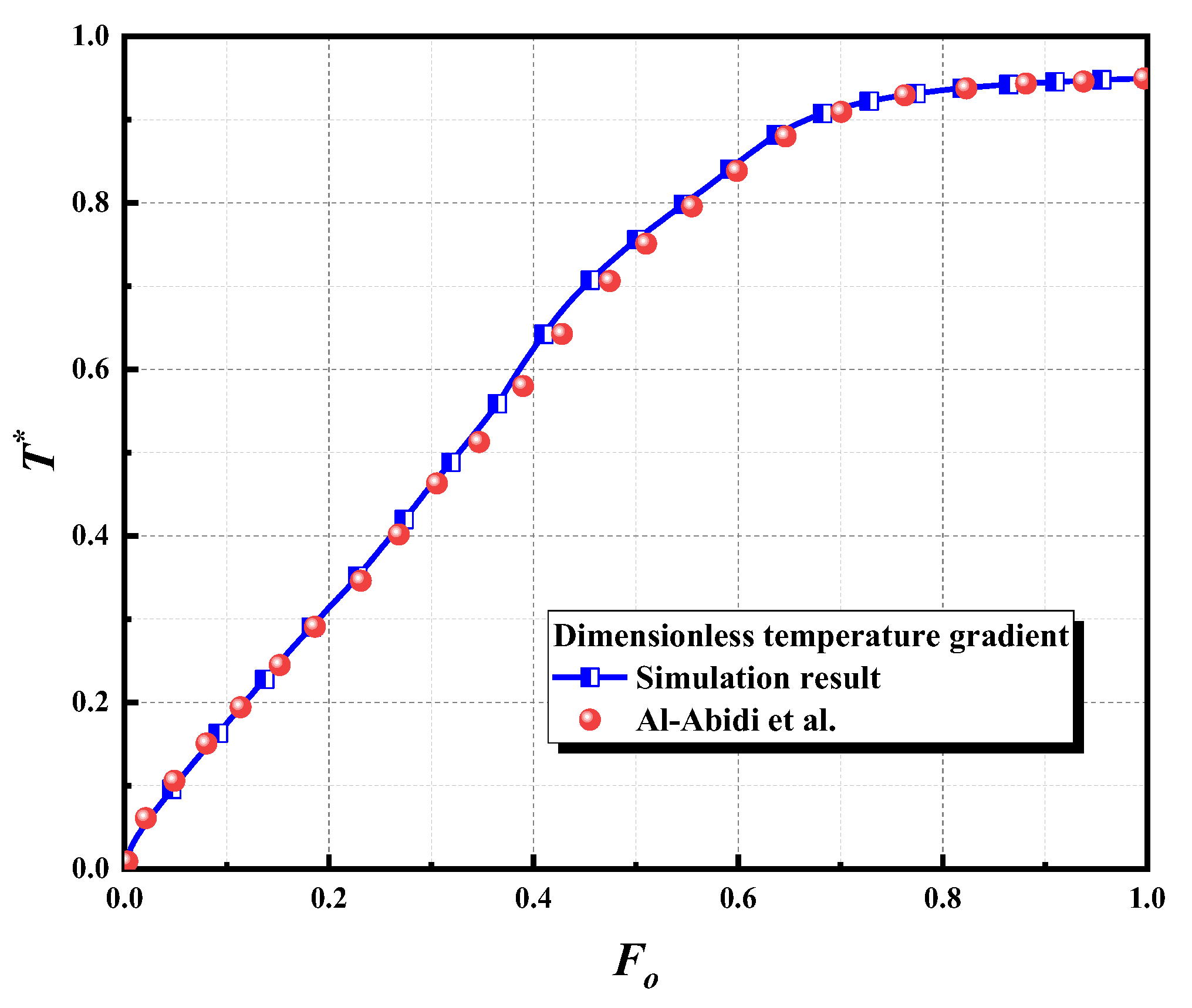
Figure 6.
The liquid phase distribution at different time.
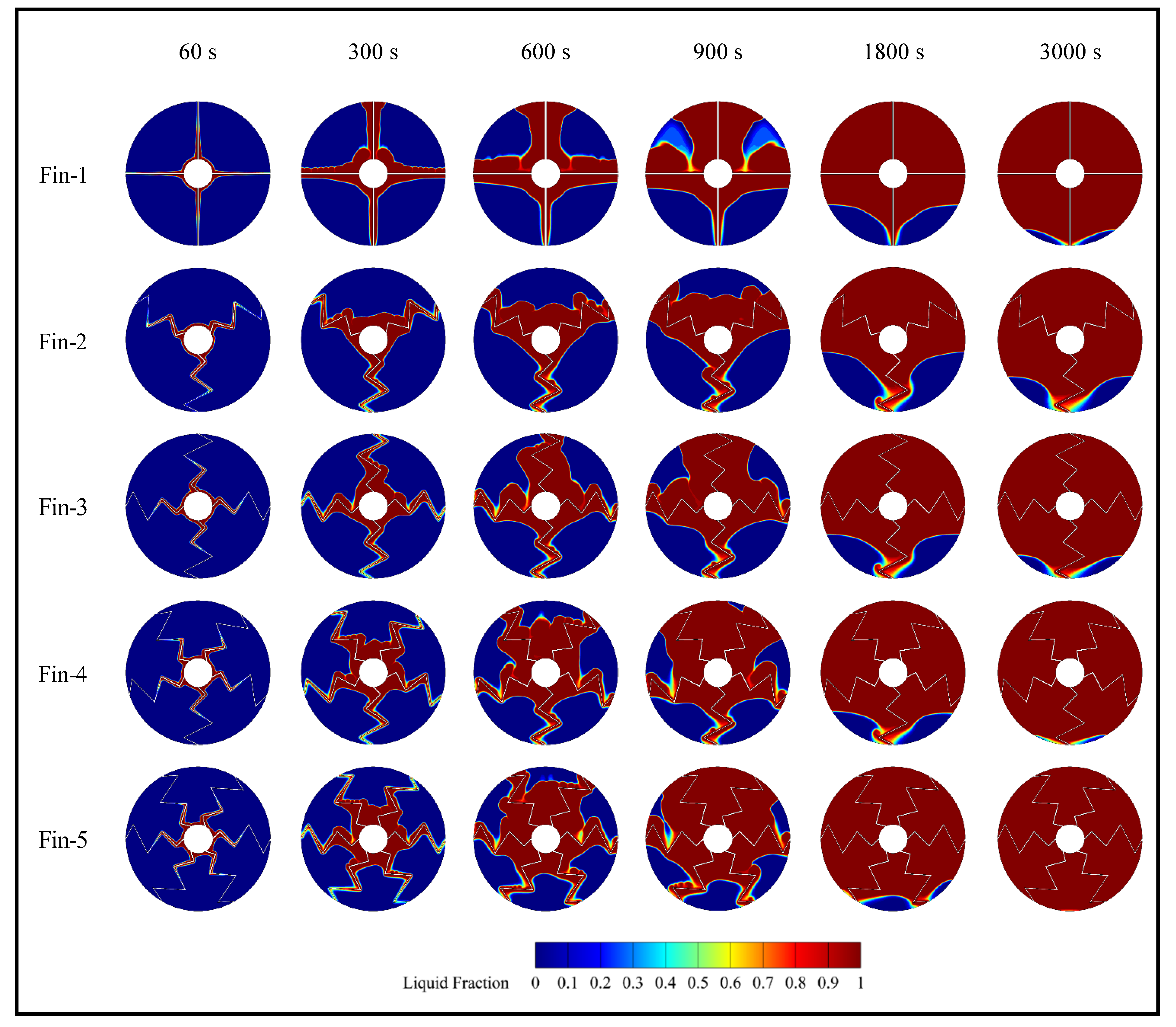
Figure 7.
The distribution of temperature at different time.
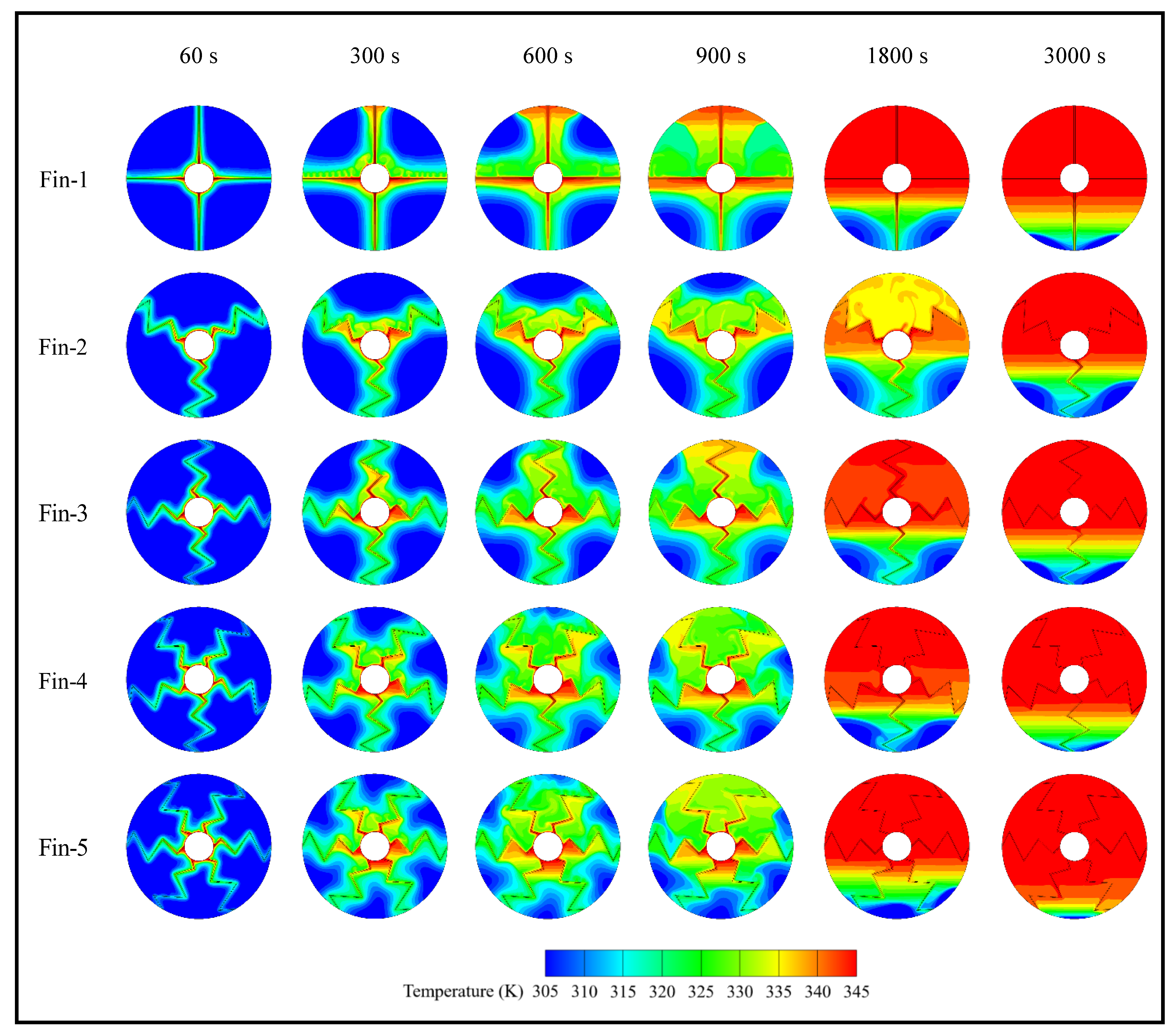
Figure 8.
Comparison of: (a) liquid phase fraction; (b) average temperature of PCM; (c) melting rate; and (d) melting time.
Figure 8.
Comparison of: (a) liquid phase fraction; (b) average temperature of PCM; (c) melting rate; and (d) melting time.

Figure 9.
(a) sensible heat energy; (b) latent heat energy; (c) total heat energy; (d) instantaneous heat absorption rate; (e) average heat absorption rate.
Figure 9.
(a) sensible heat energy; (b) latent heat energy; (c) total heat energy; (d) instantaneous heat absorption rate; (e) average heat absorption rate.
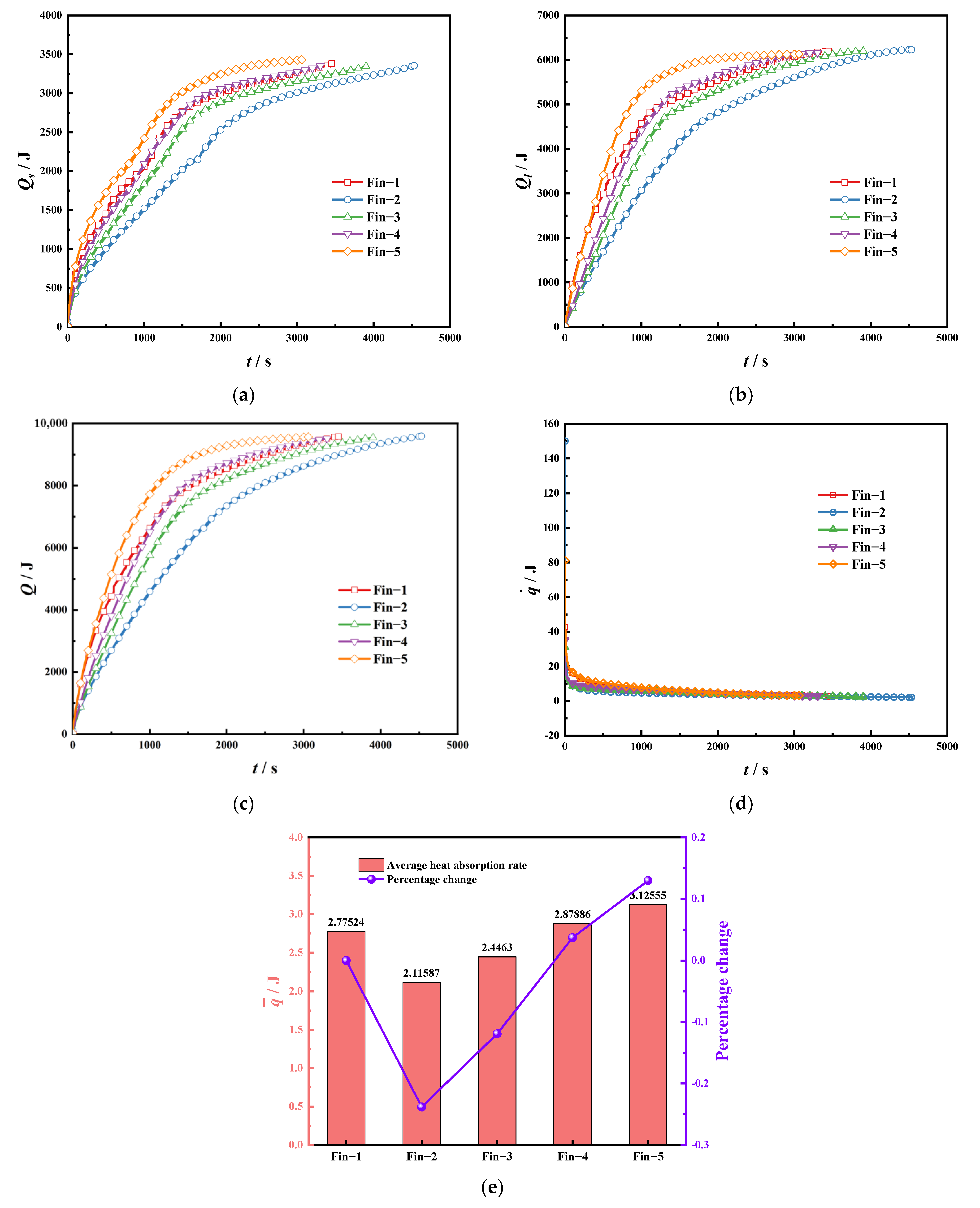
Figure 10.
Comparison of: (a) instantaneous temperature response; (b) average temperature response.


Table 1.
Model geometry parameter.
| Geometric Numbering | Numerical Value (mm) |
|---|---|
| R1 | 10 |
| R2 | 50 |
| L1 | 5 |
| L2 | 10 |
| L3 | 10 |
| L4 | 10 |
| L5 | 5 |
| d1 | 1 |
| d2 | 5 |
| d3 | 10 |
| Property | Paraffin RT50 | Paraffin RT82 | Cu | Unit |
|---|---|---|---|---|
| Thermal conductivity (k) | 0.2 | 0.2 | 387.6 | W/m·K |
| Dynamic viscosity (μ) | 0.0048 | 0.03499 | Pa·s | |
| Isobaric specific heat (cp) | 2000 | 2000 | 381 | J/kg·K |
| Density (ρ) | 760 (liq) 880(sol) | 770 (liq) 950(sol) | 8978 | kg/m3 |
| Melting temperature (Tm) | 321.15 | 353.15 | K | |
| Latent heat of fusion (λ) | 168000 | 176000 | J/kg | |
| Volumetric coefficient of thermal expansion (β) | 0.0006 | 0.001 | K−1 | |
| Solidus temperature (Ts) | 318.15 | 351.15 | K | |
| Liquidus temperature (Tl) | 324.15 | 355.15 | K |
Table 3.
Different structures correspond to the total different heat absorption during the storage cycle.
Table 3.
Different structures correspond to the total different heat absorption during the storage cycle.
| Total Sensible Heat Energy | Total Latent Heat Energy | Total Heat Energy | |
|---|---|---|---|
| Fin-1 | 3378.73231 | 6195.83858 | 9574.57088 |
| Fin-2 | 3355.46861 | 6229.44 | 9584.90861 |
| Fin-3 | 3344.71704 | 6195.83833 | 9540.55537 |
| Fin-4 | 3349.51248 | 6162.23917 | 9511.75165 |
| Fin-5 | 3432.41211 | 6128.63745 | 9561.04956 |
Disclaimer/Publisher’s Note: The statements, opinions and data contained in all publications are solely those of the individual author(s) and contributor(s) and not of MDPI and/or the editor(s). MDPI and/or the editor(s) disclaim responsibility for any injury to people or property resulting from any ideas, methods, instructions or products referred to in the content. |
© 2023 by the authors. Licensee MDPI, Basel, Switzerland. This article is an open access article distributed under the terms and conditions of the Creative Commons Attribution (CC BY) license (https://creativecommons.org/licenses/by/4.0/).
Share and Cite
MDPI and ACS Style
Ning, T.; Huang, X.; Su, J.; Yang, X. Design and Research of Heat Storage Enhancement by Innovative Wave Fin in a Hot Water–Oil-Displacement System. Sustainability 2023, 15, 15785. https://doi.org/10.3390/su152215785
AMA Style
Ning T, Huang X, Su J, Yang X. Design and Research of Heat Storage Enhancement by Innovative Wave Fin in a Hot Water–Oil-Displacement System. Sustainability. 2023; 15(22):15785. https://doi.org/10.3390/su152215785
Chicago/Turabian StyleNing, Tao, Xinyu Huang, Junwei Su, and Xiaohu Yang. 2023. "Design and Research of Heat Storage Enhancement by Innovative Wave Fin in a Hot Water–Oil-Displacement System" Sustainability 15, no. 22: 15785. https://doi.org/10.3390/su152215785
Note that from the first issue of 2016, this journal uses article numbers instead of page numbers. See further details here.