
An Experimental Study on Seismic Performance Evaluation of Multi-Ply Bellows Type Expansion Joint for Piping Systems


Abstract
:1. Introduction
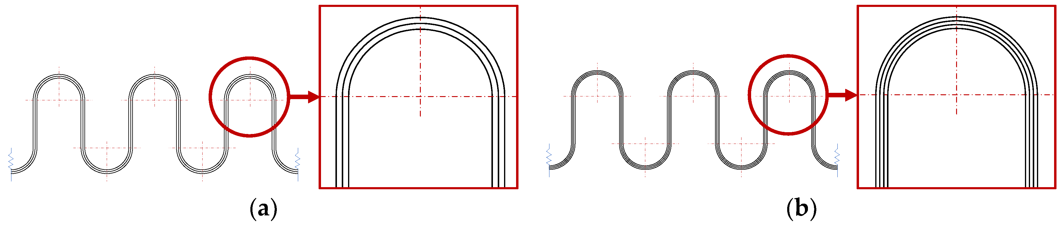
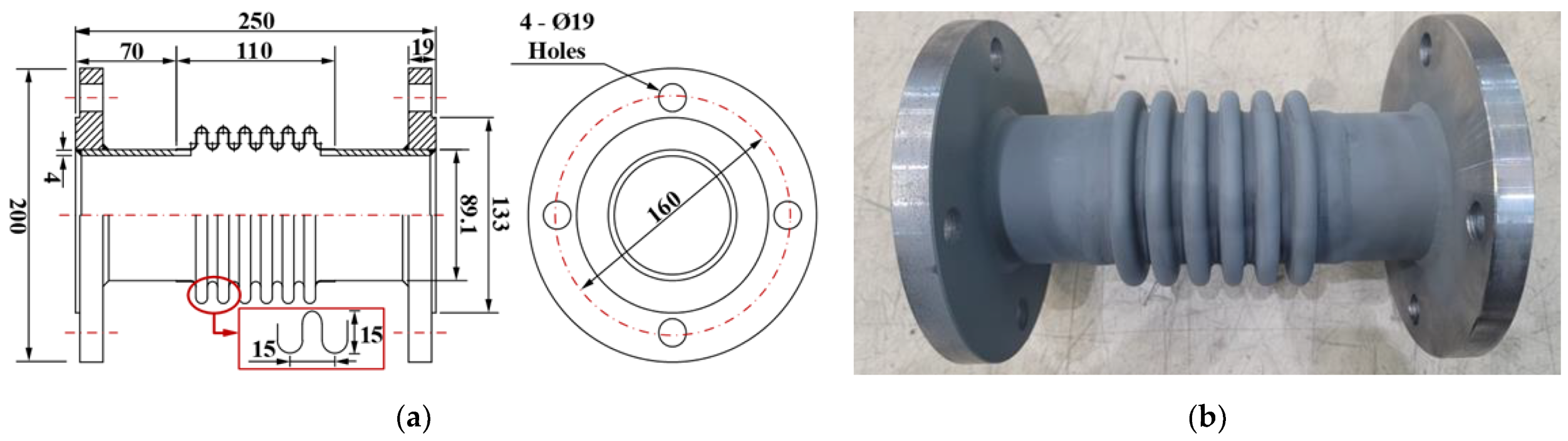
2. Test Specimen
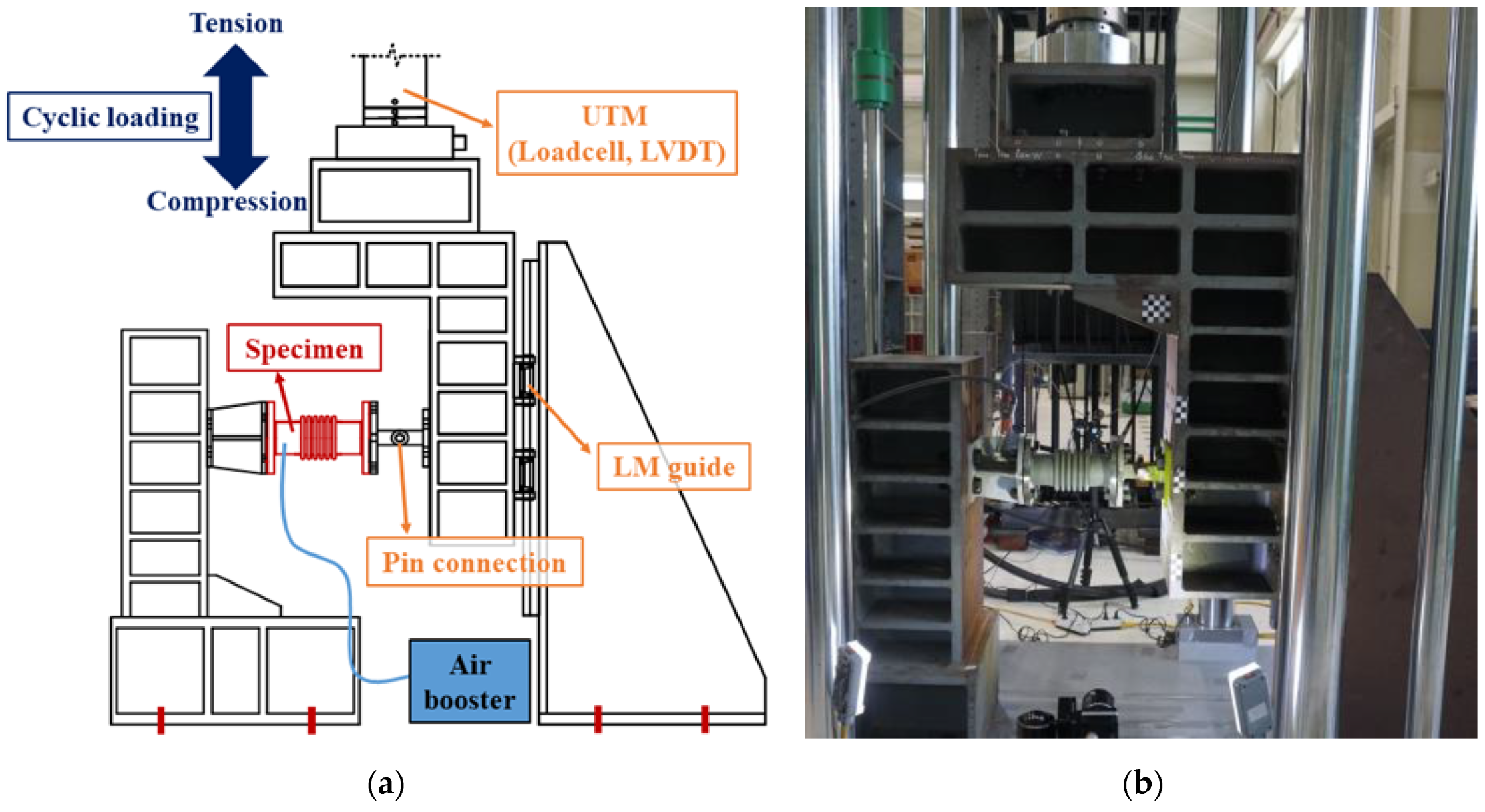
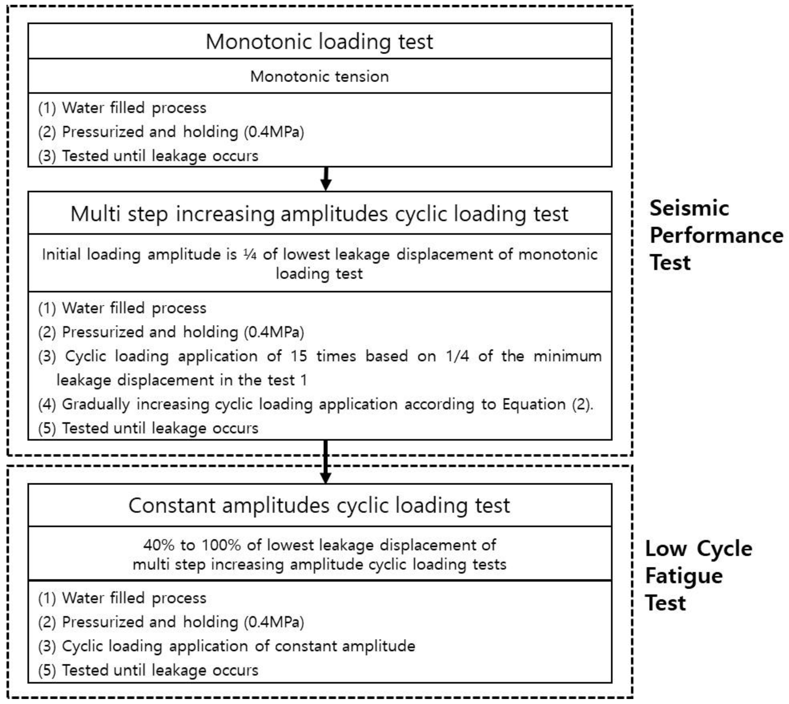
3. Test Setup and Method
4. Experiment Results and Analysis
5. Conclusions
Author Contributions
Funding
Institutional Review Board Statement
Informed Consent Statement
Data Availability Statement
Acknowledgments
Conflicts of Interest
References
- Perrone, D.; Calvi, P.M.; Nascimbene, R.; Fischer, E.C.; Magliulo, G. Seismic performance of non-structural elements during the 2016 Central Italy earthquake. Bull. Earthq. Eng. 2019, 17, 5655–5677. [Google Scholar] [CrossRef]
- Belleri, A.; Brunesi, E.; Nascimbene, R.; Pagani, M. Seismic Performance of Precast Industrial Facilities Following Major Earthquakes in the Italian Territory. J. Perform. Constr. Facil. 2015, 29, 04014135. [Google Scholar] [CrossRef] [Green Version]
- Brunesi, E.; Nascimbene, R.; Pagani, M.; Beilic, D. Seismic Performance of Storage Steel Tanks during the May 2012 Emilia, Italy, Earthquakes. J. Perform. Constr. Facil. 2015, 29, 04014137. [Google Scholar] [CrossRef]
- Yasuda, S.; Kiku, H. Uplift of sewage manholes and pipes during the 2004 Niigataken-chuetsu earthquake. Soils Found. 2006, 46, 885–894. [Google Scholar] [CrossRef] [Green Version]
- Yasuda, S.; Harada, K.; Ishikawa, K.; Kanemaru, Y. Characteristics of liquefaction in Tokyo Bay area by the 2011 Great East Japan Earthquake. Soils Found. 2012, 52, 793–810. [Google Scholar] [CrossRef] [Green Version]
- Donald, B. Understanding the Seismic Vulnerability of Water Systems. 2013. Available online: https://docplayer.net/7985651-ofWaterUnderstanding-the-seismic-vulnerability-of-water-systems.html (accessed on 2 October 2013).
- American Society of Civil Engineers; Structural Engineering Institute (ASCE/SEI). ASCE 7–16: Minimum Design Loads and Associated Criteria for Buildings and Other Structures; ASCE: Reston, VA, USA, 2017. [Google Scholar]
- Kim, S.W.; Jeon, B.G.; Ahn, S.W.; Wi, S.W. Seismic behavior of riser pipes with pressure and groove joints using an in-plane cyclic loading test. J. Build. Eng. 2021, 34, 101911. [Google Scholar] [CrossRef]
- Edkins, D.J.; Orense, R.P.; Henry, R.S. Seismic simulation testing of PVC-U pipe and proposed design prediction tool for joint performance. J. Pipeline Syst. Eng. Pract. 2021, 12, 04021007. [Google Scholar] [CrossRef]
- Ihnotic, C.R.; Ramos, J.L.; Wham, B.P. Seismic Evaluation of Hazard-Resistant Pipelines: PVC, PVCO, and iPVC Pipe with Coupling; University of Colorado Boulder: Boulder, CO, USA, 2019. [Google Scholar]
- Wham, B.P.; O’Rourke, T.D.; Stewart, H.E.; Bond, T.K.; Pariya-Ekkasut, C. Large-Scale Testing of JFE Steel Pipe Crossing Faults: Testing of SPF Wave Feature to Resist Fault Rupture; Cornell University: Ithaca, NY, USA, 2016. [Google Scholar]
- Lv, Y.; Liu, C.F.; Huang, X.; Chen, Y.; Chouw, N. Experimental and finite-element studies of buried pipes connected by a bellow Joint under Cyclic Shear Loading. J. Pipeline Syst. Eng. Pract. 2021, 12, 04021057. [Google Scholar] [CrossRef]
- Gu, F.; Zhou, J.; Hai, H.; Song, Y. Pullout test study on flexible joint of ductile iron buried pipelines. Adv. Mater. Res. 2012, 368–373, 1130–1133. [Google Scholar] [CrossRef]
- Jang, Y.C.; Kim, I.J.; Kim, C.M.; Jeon, B.G.; Chang, S.J.; Kim, Y.P. A Study on the Deformation Characteristics of Gas Pipeline under Internal Pressure and In-Plane Bending Load. Trans. Korean Soc. Press. Vessel. Pip. 2019, 15, 50–57. [Google Scholar]
- Varelis, G.E.; Ferino, J.; Karamanos, S.A.; Lucci, A.; Demofonti, G. Experimental and Numerical Investigation of Pressurized Pipe Elbows under Strong Cyclic Loading Conditions. In Proceedings of the ASME 2013 Pressure Vessels & Piping Division Conference, Paris, France, 14–18 July 2013. [Google Scholar]
- Jeon, B.G.; Kim, S.W.; Choi, H.S.; Park, D.U.; Kim, N.S. A Failure Estimation Method of Steel Pipe Elbows under In-plane Cyclic Loading. Nucl. Eng. Technol. 2017, 49, 245–253. [Google Scholar] [CrossRef]
- Kim, S.W.; Choi, H.S.; Jeon, B.G.; Hahm, D.G. Low-cycle fatigue behaviors of the elbow in a nuclear power plant piping system using the moment and deformation angle. Eng. Fail. Anal. 2019, 96, 348–361. [Google Scholar] [CrossRef]
- Pappa, P.; Varelis, G.E.; Karamanos, S.A.; Gresnigt, A.M. Low Cycle Fatigue Tests and Simulations on Steel Elbows. In Proceedings of the ASME 2013 Pressure Vessels & Piping Division Conference, Paris, France, 14–18 July 2013. [Google Scholar]
- Takahashi, K.; Watanabe, S.; Ando, K.; Urabe, Y.; Hidaka, A.; Hisatsune, M.; Miyazaki, K. Low cycle fatigue behaviors of elbow pipe with local wall thinning. Nucl. Eng. Des. 2009, 239, 2719–2727. [Google Scholar] [CrossRef]
- Kim, S.W.; Chang, S.J.; Park, D.U.; Jeon, B.G. Failure criteria of a carbon steel pipe elbow for low-cycle fatigue using the damage index. Thin-Walled Struct. 2020, 153, 106800. [Google Scholar] [CrossRef]
- Kim, S.W.; Jeon, B.G.; Hahm, D.G.; Kim, M.K. Ratcheting fatigue failure of a carbon steel pipe tee in a nuclear power plant using the deformation angle. Eng. Fail. Anal. 2020, 114, 104595. [Google Scholar] [CrossRef]
- Nuclear Energy Agency (NEA); Committee on the Safety of Nuclear Installations (CSNI). Integrity of Structures, Systems and Components under Design and Beyond Design Loads in Nuclear Power Plants, Final Report of the Project on Metallic Component Margins under High Seismic Loads (MECOS); NEA: Paris, France, 2018.
- Soroushian, S.; Zaghi, A.E.; Maragakis, E.M.; Echevarria, A.; Tian, Y.; Filiatrault, A. Seismic fragility study of fire sprinkler piping systems with grooved fit joints. J. Struct. Eng. 2015, 141, 04014157. [Google Scholar] [CrossRef]
- Kim, S.W.; Yun, D.W.; Jeon, B.G.; Kim, J.B. Seismic performance evaluation of a vertical pipe connected with rigid groove joints using a system and a component. Structures 2022, 36, 691–702. [Google Scholar] [CrossRef]
- Ju, B.S.; Jeon, B.G.; Kim, S.W.; Son, H.Y. Validation of Seismic Performance of Stainless Press-to-Connect Piping System under Cyclic Loadings. Appl. Sci. 2022, 12, 3896. [Google Scholar] [CrossRef]
- Perrone, D.; Brunesi, E.; Filiatrault, A.; Peloso, S.; Nascimbene, R.; Beiter, C.; Piccinin, R. Seismic Numerical Modelling of Suspended Piping Trapeze Restraint Installations based on Component Testing. Bull. Earthq. Eng. 2020, 18, 3247–3283. [Google Scholar] [CrossRef]
- Kim, S.W.; Jeon, B.G.; Hahm, D.G.; Kim, M.K. Seismic fragility evaluation of the base-isolated nuclear power plant piping system using the failure criterion based on stress-strain. Nucl. Eng. Technol. 2019, 51, 561–572. [Google Scholar] [CrossRef]
- Jeon, B.G.; Kim, S.W.; Yun, D.W.; Hahm, D.G.; Eem, S.H. Seismic Fragility Evaluation of Main Steam Piping of Isolated APR1400 NPP Considering the Actual Failure Mode. Sustainability 2022, 14, 8315. [Google Scholar] [CrossRef]
- National Fire Protection Association (NFPA). Standard for the Installation of Sprinkler Systems; NFPA: Quincy, MA, USA, 2013. [Google Scholar]
- Lv, Y.; Liu, C.F.; Huang, X.; Chen, Y.; Chouw, N. Experimental and finite-element study of buried pipes connected by bellow joint under axial cyclic loading. J. Pipeline Syst. Eng. Pract. 2021, 12, 04020069. [Google Scholar] [CrossRef]
- Kim, P.S.; Kim, J.D. Performance evaluation of the forming methods used in the production of bellows for LNG carriers I—Comparison of design methods and mechanical properties of bellows. J. Adv. Mar. Eng. Technol. 2016, 40, 587–592. [Google Scholar] [CrossRef]
- KS D 3631; Carbon Steel Pipes for Fuel Gas Piping. Korea Agency for Technology and Standards (KS): Eumseong, Korea, 2020.
- KS D 3503; Rolled Steels for General Structure. Korea Agency for Technology and Standards (KS): Eumseong, Korea, 2018.
- KGS FU551; Facility/Technical/Inspection Code for Urban Gas Using Facilities. Korea Gas Safety Corporation (KGS): Eumseong, Korea, 2021.
- ANSI/FM Approvals 1950; American National Standard for Seismic Sway Braces for Pipe, Tubing and Conduit. American National Standards Institute (ANSI): Washington, DC, USA, 2016.
- KS B 1528; Seismic Safety Test Method for Pipe Connecting Parts. Korea Agency for Technology and Standards (KS): Eumseong, Korea, 2019.
- Malhotra, P.K.; Sensery, P.E.; Braga, A.C.; Allard, R.L. Testing sprinkler-pipe seismic-brace components. Earthq. Spectra 2003, 19, 87–109. [Google Scholar] [CrossRef]
- FEMA 461; Interim Testing Protocols for Determining the Seismic Performance Characteristics of Structural and Nonstructural Components. Federal Emergency Management Agency (FEMA): Washington, DC, USA, 2007.
- ISO 16134; Earthquake-Resistant and Subsidence-Resistant Design of Ductile Iron Pipelines. International Organization for Standardization (ISO): Geneva, Switzerland, 2020.

| Yield Strength (N/mm2) | Tensile Strength (N/mm2) | Elongation (%) | |
|---|---|---|---|
| STS 316L | 257 | 563 | 52.7 |
| Test Method | No. | Leakage Point | Remarks | |||
|---|---|---|---|---|---|---|
| Displacement (mm) | Angle (Degree) | Location | ||||
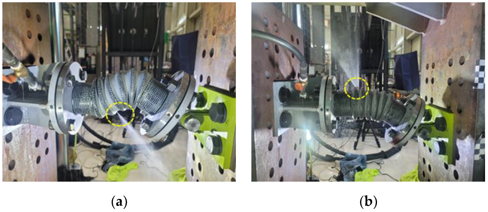
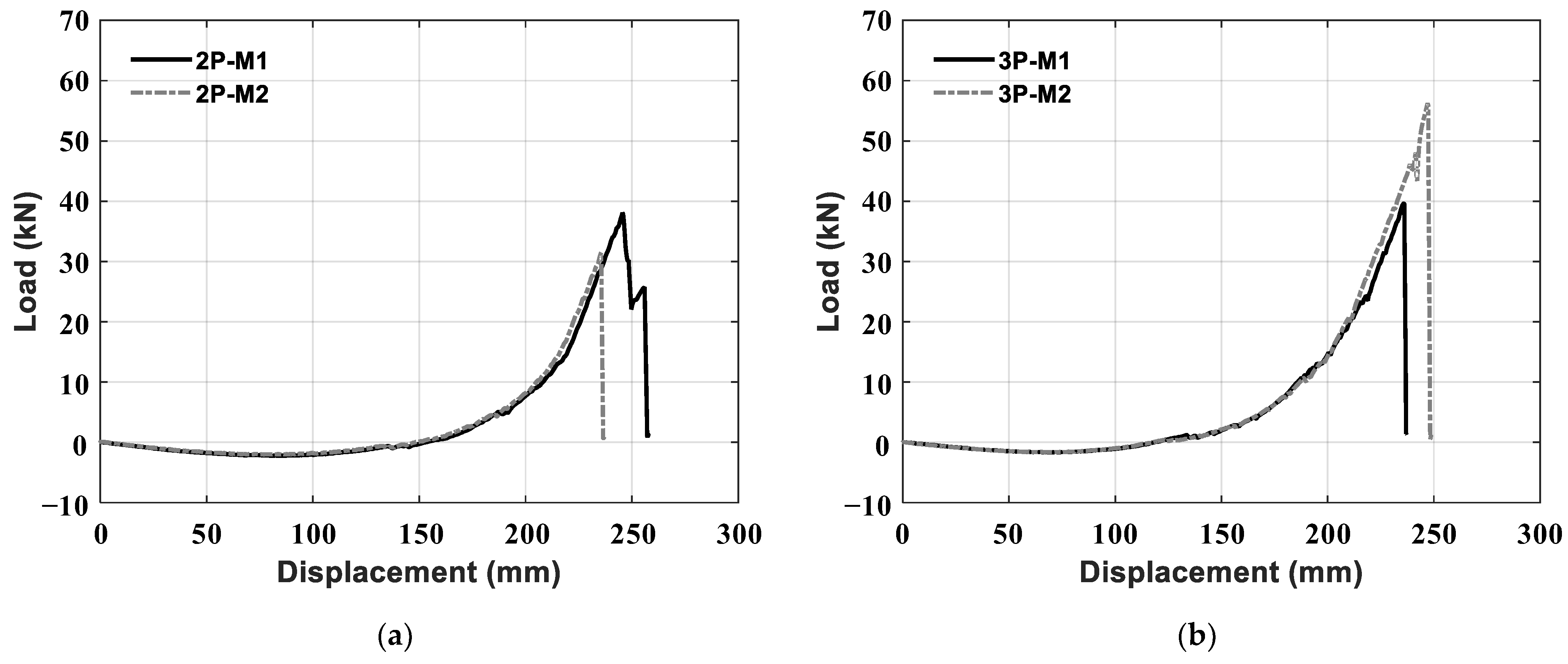
| Monotonic | 2P-M1 | 257.8 | 39.8 | Pipe-bellows welding | - | Lowest leakage displacement: 237.1 mm |
| 2P-M2 | 237.1 | 37.5 | - | |||
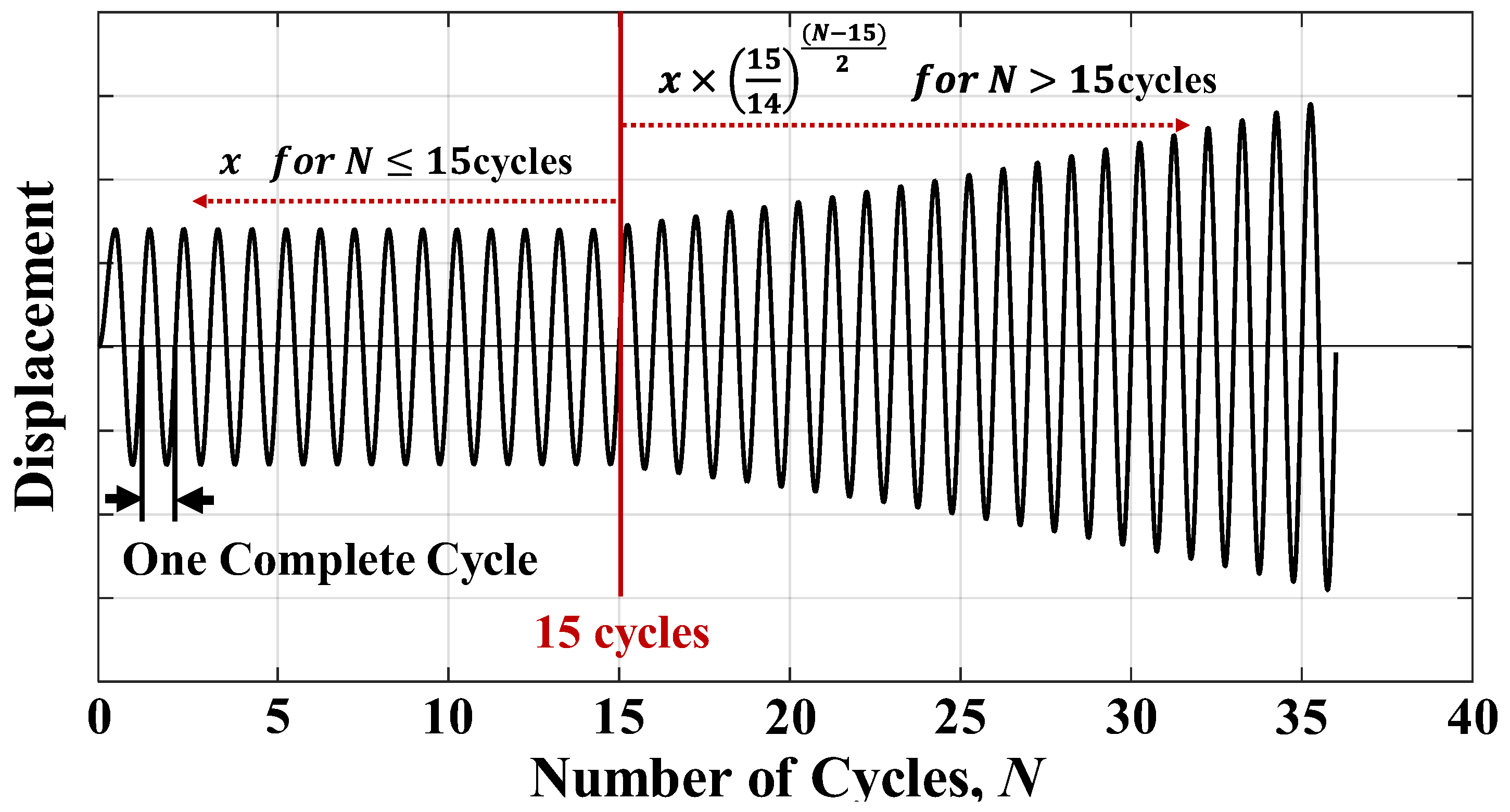
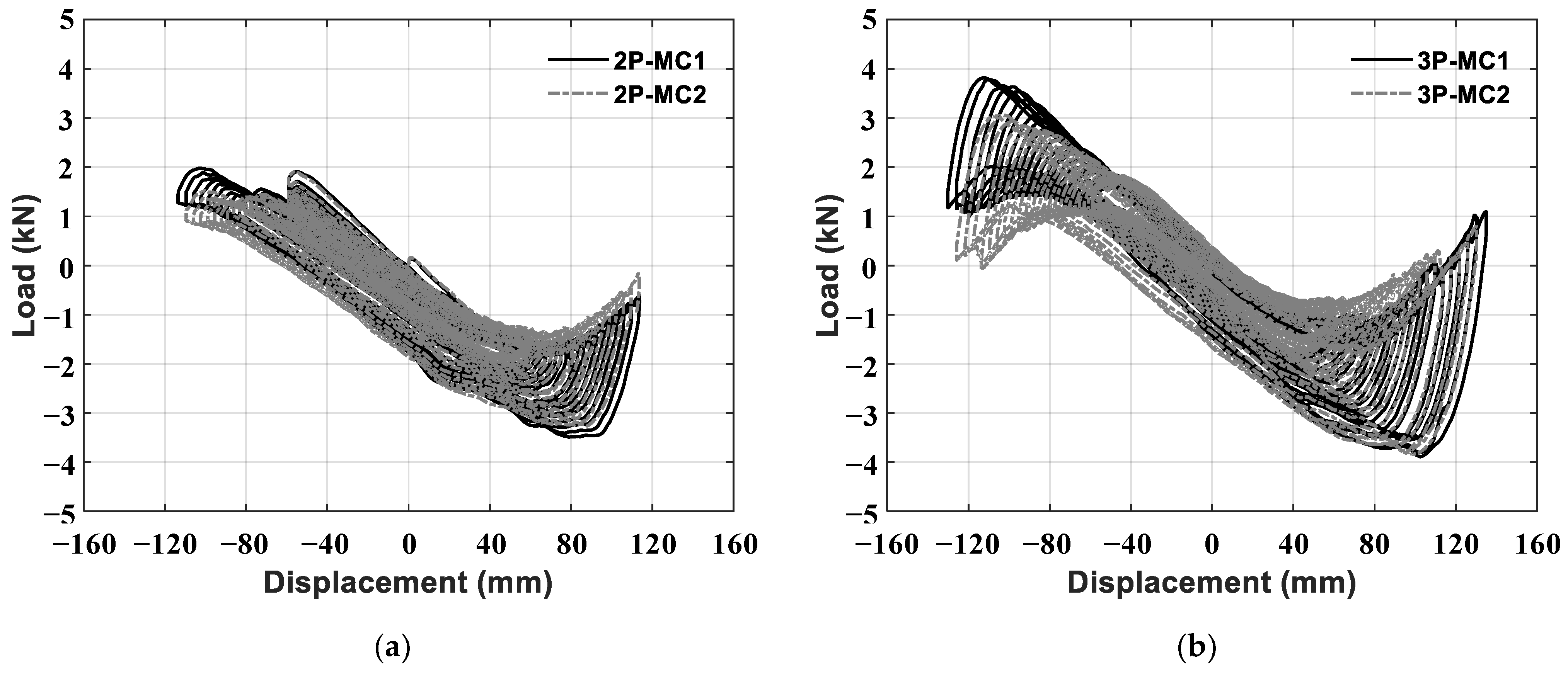
| Multi-step increasing amplitude cyclic | 2P-MC1 | 113.6 | 20.2 | Convolutions of bellows | 34 | Initial amplitude: 59 mm |
| 2P-MC2 | 113.6 | 20.2 | 34 | |||
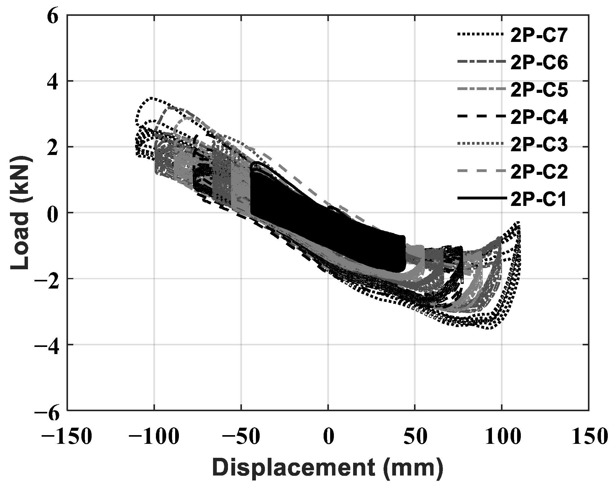
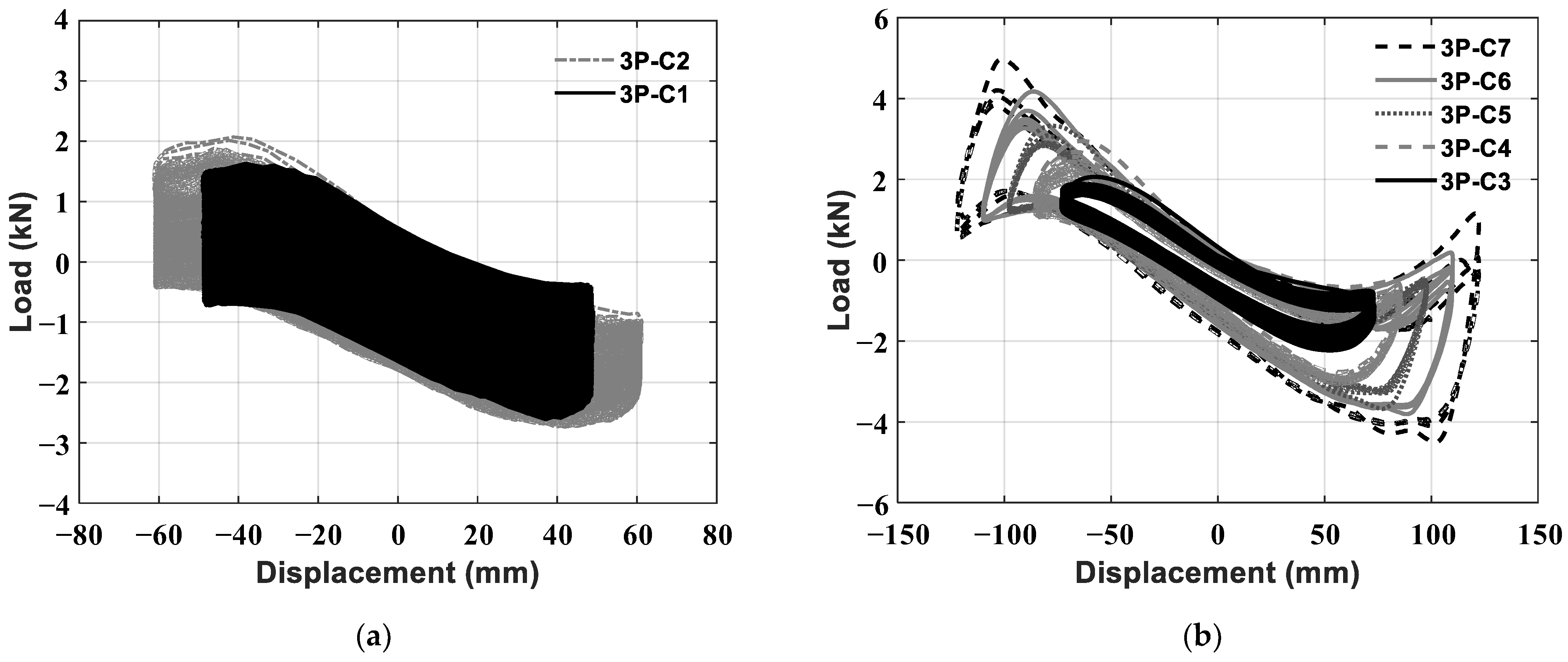
| Constant amplitude cyclic | 2P-C1 | 44.0 | 8.1 | Convolutions of bellows | 592 | Amp. 40% |
| 2P-C2 | 55.0 | 10.1 | 74 | Amp. 50% | ||
| 2P-C3 | 66.0 | 12.1 | 43 | Amp. 60% | ||
| 2P-C4 | 77.0 | 14.0 | 22 | Amp. 70% | ||
| 2P-C5 | 88.0 | 15.9 | 17 | Amp. 80% | ||
| 2P-C6 | 99.0 | 17.8 | 13 | Amp. 90% | ||
| 2P-C7 | 110.0 | 19.6 | 6 | Amp. 100%: Amplitude of cycle before minimum leakage displacement at multi-step increasing amplitude cyclic test | ||
| Test Method | No. | Leakage Point | Remarks | |||
|---|---|---|---|---|---|---|
| Displacement (mm) | Angle (Degree) | Location | ||||
| Monotonic | 3P-M1 | 237.0 | 37.5 | Pipe-bellows welding | - | Lowest leakage displacement: 237 mm |
| 3P-M2 | 248.7 | 38.8 | - | |||
| Multi-step increasing amplitude cyclic | 3P-MC1 | 126.0 | 22.2 | Convolutions of bellows | 37 | Initial amplitude: 59 mm |
| 3P-MC2 | 130.5 | 22.9 | 38 | |||
| Constant amplitude cyclic | 3P-C1 | 48.8 | 9.0 | Convolutions of bellows | 1949 | Amp. 40% |
| 3P-C2 | 61.0 | 11.2 | 406 | Amp. 50% | ||
| 3P-C3 | 73.2 | 13.3 | 153 | Amp. 60% | ||
| 3P-C4 | 85.4 | 15.4 | 46 | Amp. 70% | ||
| 3P-C5 | 97.6 | 17.5 | 10 | Amp. 80% | ||
| 3P-C6 | 109.8 | 19.6 | 7 | Amp. 90% | ||
| 3P-C7 | 122.0 | 21.5 | 4 | Amp. 100%: Amplitude of cycle before minimum leakage displacement at multi-step increasing amplitude cyclic test | ||
| Difference in Leakage Point (%) | ||||
|---|---|---|---|---|
| 2-Ply Bellows | 3-Ply Bellows | |||
| Displacement | Angle | Displacement | Angle | |
| Monotonic | 8.4 | 6.0 | 4.8 | 3.4 |
| Multi-step increasing amplitude cyclic | 0.0 | 0.0 | 3.5 | 3.1 |
| Specimen Type | Leakage Displacement | Leakage Angle | Ratio (MC/M) | |||
|---|---|---|---|---|---|---|
| Monotonic [M] | Multi-Step Increasing Cyclic Loading [MC] | Monotonic [M] | Multi-Step Increasing Cyclic Loading [MC] | Leakage Displacement | Leakage Angle | |
| 2-ply | 237.1 mm | 113.6 mm | 37.5° | 20.2° | 0.48 | 0.54 |
| 3-ply | 237.0 mm | 126.0 mm | 37.5° | 22.2° | 0.53 | 0.59 |
| Difference | 0.0% | 10.4% | 0.0% | 9.4% | - | - |
| Specimen Type | 2-Ply Bellows | 3-Ply Bellows | |||
|---|---|---|---|---|---|
| Unit | Minimum Leakage Displacement (mm) | Minimum Leakage Angle (Degree) | Minimum Leakage Displacement (mm) | Minimum Leakage Angle (Degree) | |
| Leakage point | Monotonic [M] | 237.1 | 37.5 | 237 | 37.5 |
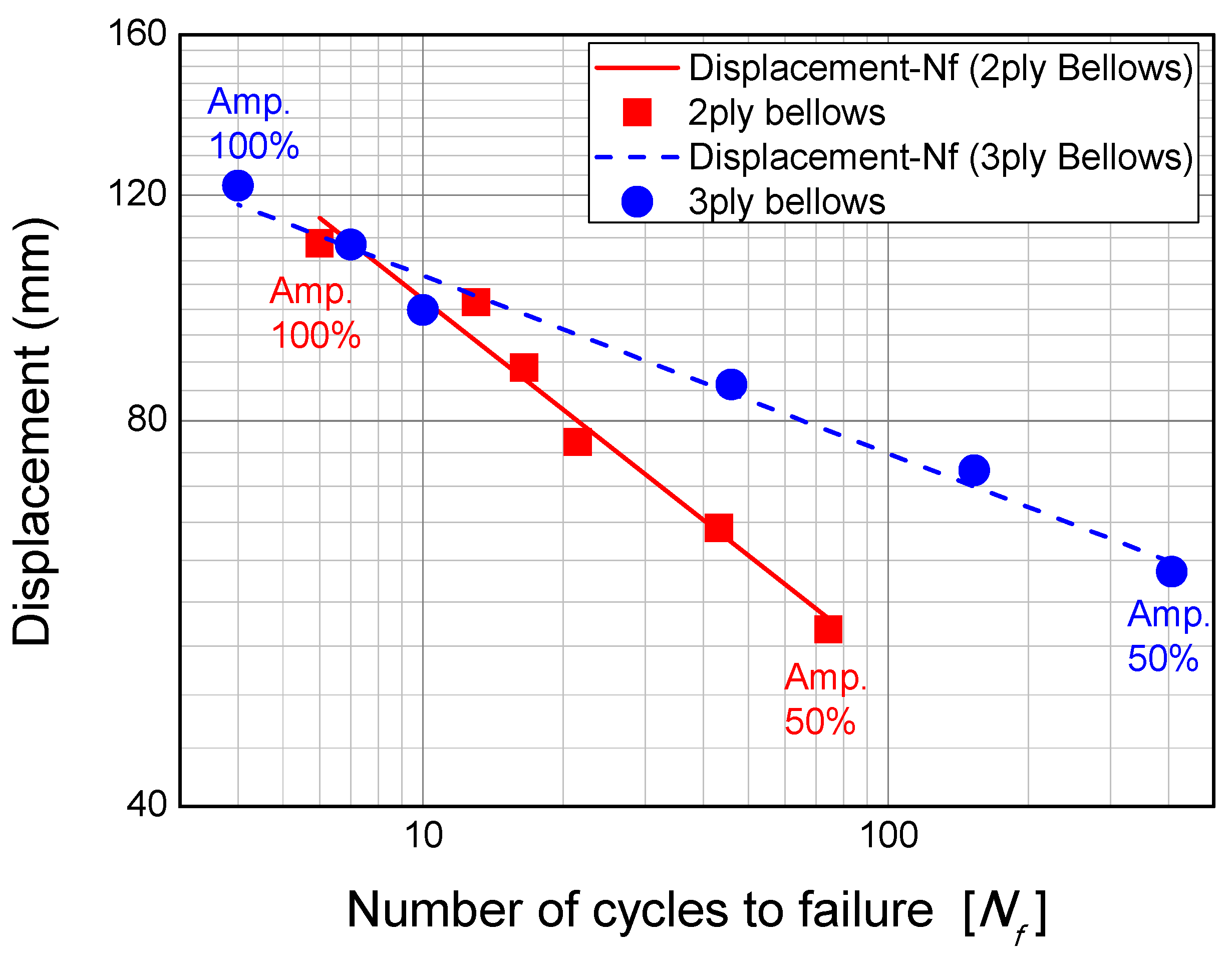
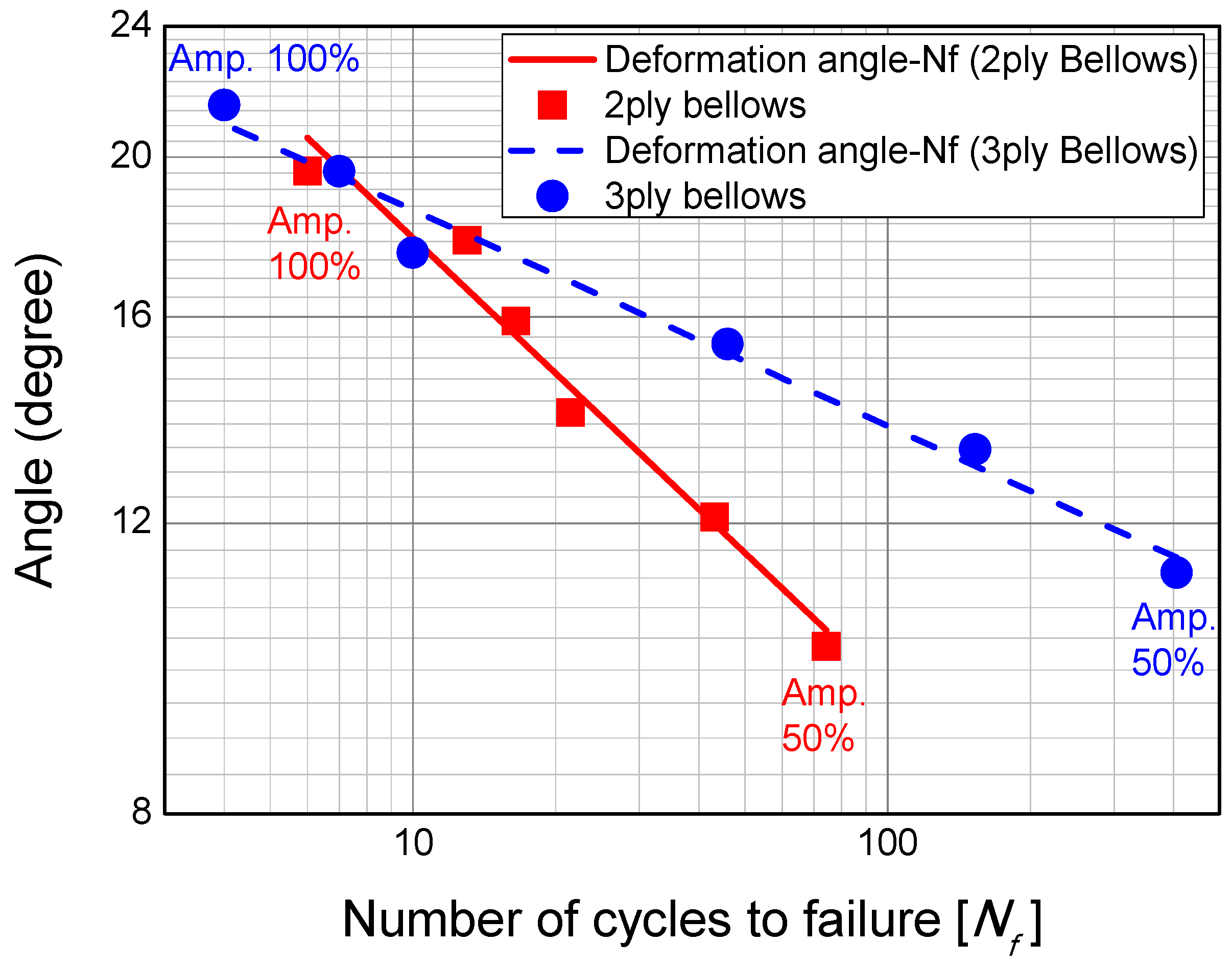
| Amplitude 50% of constant amplitude cyclic loading [Amp. 50%] | 55.0 | 10.1 | 61 | 11.2 | |
| Ratio of failure | Amp. 50%/M | 0.23 | 0.27 | 0.26 | 0.30 |
Publisher’s Note: MDPI stays neutral with regard to jurisdictional claims in published maps and institutional affiliations. |
© 2022 by the authors. Licensee MDPI, Basel, Switzerland. This article is an open access article distributed under the terms and conditions of the Creative Commons Attribution (CC BY) license (https://creativecommons.org/licenses/by/4.0/).
Share and Cite
Jeon, B.-G.; Kim, S.-W.; Yun, D.-W.; Ju, B.-S.; Son, H.-Y. An Experimental Study on Seismic Performance Evaluation of Multi-Ply Bellows Type Expansion Joint for Piping Systems. Sustainability 2022, 14, 14777. https://doi.org/10.3390/su142214777
Jeon B-G, Kim S-W, Yun D-W, Ju B-S, Son H-Y. An Experimental Study on Seismic Performance Evaluation of Multi-Ply Bellows Type Expansion Joint for Piping Systems. Sustainability. 2022; 14(22):14777. https://doi.org/10.3390/su142214777
Chicago/Turabian StyleJeon, Bub-Gyu, Sung-Wan Kim, Da-Woon Yun, Bu-Seog Ju, and Ho-Young Son. 2022. "An Experimental Study on Seismic Performance Evaluation of Multi-Ply Bellows Type Expansion Joint for Piping Systems" Sustainability 14, no. 22: 14777. https://doi.org/10.3390/su142214777