
Operating Principles, Performance and Technology Readiness Level of Reversible Solid Oxide Cells

Department of Civil, Chemical and Environmental Engineering, University of Genova, 16145 Genova, Italy
*
Author to whom correspondence should be addressed.
Sustainability 2021, 13(9), 4777; https://doi.org/10.3390/su13094777
Submission received: 16 March 2021
/
Revised: 15 April 2021
/
Accepted: 22 April 2021
/
Published: 24 April 2021
(This article belongs to the Special Issue Climate Adaptation and Mitigation through Sustainable Energy Solutions)
Abstract
:The continuous increase of energy demand with the subsequent huge fossil fuel consumption is provoking dramatic environmental consequences. The main challenge of this century is to develop and promote alternative, more eco-friendly energy production routes. In this framework, Solid Oxide Cells (SOCs) are a quite attractive technology which could satisfy the users’ energy request working in reversible operation. Two operating modes are alternated: from “Gas to Power”, when SOCs work as fuel cells fed with hydrogen-rich mixture to provide both electricity and heat, to “Power to Gas”, when SOCs work as electrolysers and energy is supplied to produce hydrogen. If solid oxide fuel cells are an already mature technology with several stationary and mobile applications, the use of solid oxide electrolyser cells and even more reversible cells are still under investigation due to their insufficient lifetime. Aiming at providing a better understanding of this new technological approach, the study presents a detailed description of cell operation in terms of electrochemical behaviour and possible degradation, highlighting which are the most commonly used performance indicators. A thermodynamic analysis of system efficiency is proposed, followed by a comparison with other available electrochemical devices in order to underline specific solid oxide cell advantages and limitations.
1. Introduction
One of the main global challenges is the reduction of greenhouse gas emissions in order to decrease climate changes and environmental pollution, having as a goal the achievement of carbon neutrality by 2050 [1]. In 2019, the atmospheric CO2 level reached the peak of 409.8 ppm as a consequence of an annual growth rate of about 2.3 ppm since 2009 [2]. In the European context, a common action plan called the “Green Deal” was approved by different member states aiming at promoting an efficient use of the resources and at moving to a clean circular economy [3]. In order to reach this target, more and more incentives were introduced to favour the spread of renewable sources as an alternative path for the electricity production. They increased from 9.6% to 18.9% between 2004 and 2018, providing 33% of electric consumption (the remaining part derives from fossil fuel combustion and nuclear power plants for 40% and 26%, respectively). Still, this result is not sufficient, and the next target is a further increase of 32% by 2030 [4]. Nevertheless, renewable sources cannot solely be used due to their intermittent nature, so they have been successfully combined in hybrid systems with common energy sources [5,6]. In view of a smart grid based on the power balance without using fossil fuels, new technologies are requested in order to store and/or convert the energy, solving the temporal mismatch in supply and demand. These systems should be reliable with high stored energy density and round-trip energy efficiency, affordable, easy to scale, having a long lifetime and minimum environmental impacts [7]. There are already some mature technologies, such as pump hydro-systems (electricity-potential energy conversion), flywheels (electricity-rotational energy conversion), batteries (electricity-electrochemical energy conversion) and thermal energy storages (electricity-thermal energy conversion). Nevertheless, they are not suitable for every specific situation. For instance, the first are long-lasting but the initial investment cost and the specific requested geomorphology reduce possible applications [8]. The flywheels and thermal energy storages reach efficiencies higher than 90%, but a considerable self-discharge occurs [9,10]. Batteries are characterised by a fast response to variable loads; on the other hand, maintenance works are unavoidable after a few operation cycles [11].
A quite new alternative consists of reversible electrochemical cells, based on Power to Gas (PtG) and Gas to Power (GtP) approaches. When there is a surplus, the electricity is stored as chemical energy of produced species (mainly hydrogen) through electrolysis and then it can be reconverted in fuel cell operation to satisfy users’ demand. At the commercial level, there are different cell types: the alkaline technology has long-established megawatt scale applications in both modes, still the low operating temperature does not permit to reach high efficiency, above all during electrolysis operation due to the relevant input power [12]. Also, protonic exchange membrane cells are quite well-known devices, nevertheless the reversible operation of the same unit is not possible since the common catalysts used for the oxygen reduction in fuel cell mode have a low performance for the oxygen production in electrolysis mode [13]. Due to these limits, a new road was opened by high-temperature Solid Oxide Cells (SOCs), which allow for a single bifunctional unit characterised by a superior round-trip energy efficiency. Indeed, the requested voltage to split water is reduced since a part of inlet energy is provided as heat. On the other hand, the high thermal inertia does not permit to use SOCs for the frequency regulation of electric grid, making them more suitable to level loads, to shave peaks of production and as seasonal energy storage [7]. Currently, SOCs are not yet competitive on the market due to quite high capital costs, however they will be partially reduced through economy of scale: from 2000 to 530 € kWel−1 by 2050 [14]. Consequently, the operating costs will have a more relevant weight, mainly depending on national electricity price [15]. For this reason, the introduction of renewable sources as energy providers for electrolytic cells could make their operation more affordable; on the other hand, hydrogen is a clean energy carrier which allows for overcoming the limited use of renewable sources due to their intermittency. Considering small-scale applications, this approach can be applied in residential co-generation systems, where the reversible Solid Oxide Cells (rSOCs) paired with photovoltaic panels provide requested electricity as well as heat by exploiting hot-exhausted gases [16]. During the day, when the photovoltaic system is sufficient to satisfy the request, the energy surplus is stored as hydrogen through electrolysis, while the fuel cell operation guarantees the energy demand at night or concurrently the renewable sources if there is a low solar radiation [17]. Here, this strategy supports the target achievement of near-zero energy buildings following the Directive on the Energy Performance of Buildings 2010/31/EU [18]. The proposed solution would economically favour household consumers too, since the energy export prices are usually lower than the import ones, making the direct sale of renewable energy surplus disadvantageous. Rather, according to an economic optimisation of energy use, when the price is low, it results in the cost-effective conversion of the electricity from the grid to store hydrogen and then its internal consumption to satisfy the demand when the grid energy cost is high [19]. However, rSOC technology can be introduced in a wider framework. In a neighbourhood smart energy system, all utility demands (i.e., electricity, heat, mobility and water) would be fulfilled through the Power to H3 approach, where H3 means H2, heat and H2O. Using renewable energies paired with the reversible cell operation, the household electric consumption, heating and hot water would be satisfied, and moreover, a part of stored hydrogen could be directly used as transport fuel [20]. At this scale application, the proposed integration allows for the cost reduction saving on electricity grid extension. Indeed, the installation of solar or wind parks usually requires some reinforcements in order to plateau electricity peaks. Here, the conversion of the energy surplus in hydrogen permits to decrease the required grid connection capacity [21].
A peculiarity of high-temperature electrolyser operation consists of the possibility to easily use different reactants: pure water for steam electrolysis, water with carbon dioxide to produce a syngas through co-electrolysis or only CO2 in dry electrolysis mode. Indeed, the ceramic materials are more resistant compared to noble metal catalysts of low-temperature cells and nonspecific structure rearrangements are required [7]. The produced syngas with a variable H2/CO percentage can be converted to generate CO2-neutral synthetic fuels. A downstream methanation unit produces a synthetic natural gas which has an easier utilisation than hydrogen due to the lack of a proper distribution network (only a 15 vol% H2 is allowed in existing natural gas pipelines [22]). Another possible route is the conversion into methanol that has several promising applications as both green transport fuel and feedstock for renewable plastic production [23]. Longer chain hydrocarbons can also be generated through the Fischer-Tropsch process, resulting in a CO2 neutral path [24].
This work presents reversible solid oxide cells as a quite new technology for green energy production at both the residential and industrial level, providing a detailed analysis of performance through a simulation study at different operation times. Aiming at providing a basic knowledge of cell operation, the electrochemical behaviour is described in terms of possible reaction paths and the resulting effective voltage, which should be higher in fuel cell mode representing the desired output and lower in electrolysis mode to reduce the external energy supply. A rigorous description of the thermodynamic efficiency is presented: starting from basic definitions as a function of only electrical power, further formulations are discussed also introducing the requested-generated heat to guarantee a fixed temperature operation. Here, a detailed sensitivity analysis is performed to detect dependences of the cell efficiency on working conditions, considering just Solid Oxide Fuel Cell (SOFC) and Solid Oxide Electrolyser Cell (SOEC) behaviour and then their combination to estimate the rSOC round-trip energy efficiency. All simulations are run through SIMFC/SIMEC, a local 2D model previously validated by the authors for an anode-supported cell with an anionic conductive-type electrolyte (for the complete model description and assumptions, refer to [25,26]). In view of long-term applications, the degradation rate and the resulting performance worsening are also estimated. The rSOC state-of-the-art is discussed in terms of Technology Readiness Level (TRL) and through the comparison with other available power systems, showing that SOFCs are already a mature system with initial commercial stationary applications, whereas SOECs and, above all, reversible cells request further studies and improvements to become reliable and affordable systems, in spite of different tested prototypes at the industrial level.
2. Operating Principles
The solid oxide cell operation is based on electrochemical processes which allow the direct conversion from electric to chemical energy and vice versa, guaranteeing a better reaction control and minimizing possible energy losses. The single unit is composed by an electrolyte, where ion species migrate between two electrodes with catalytic active sites, and more cells are connected in series forming planar or tubular stacks in order to obtain the desired power capacity [27]. Differently from other technologies that do not overcome about 400 K, SOC characteristic working temperatures between 923 and 1270 K permit the use of only solid layers, reaching a good conductivity through solid-state diffusion mechanisms [28]. Indeed, ceramic structures show increasing stability and conductivity at temperature rise and so obtain the target electrolyte resistance of 0.01 Ω−1 cm−1 [29]. Moreover, the required catalyst activity is reached without needing cost noble metals, which makes SOCs resistant to variable feed compositions (not limited to pure hydrogen/water/inert mixtures).
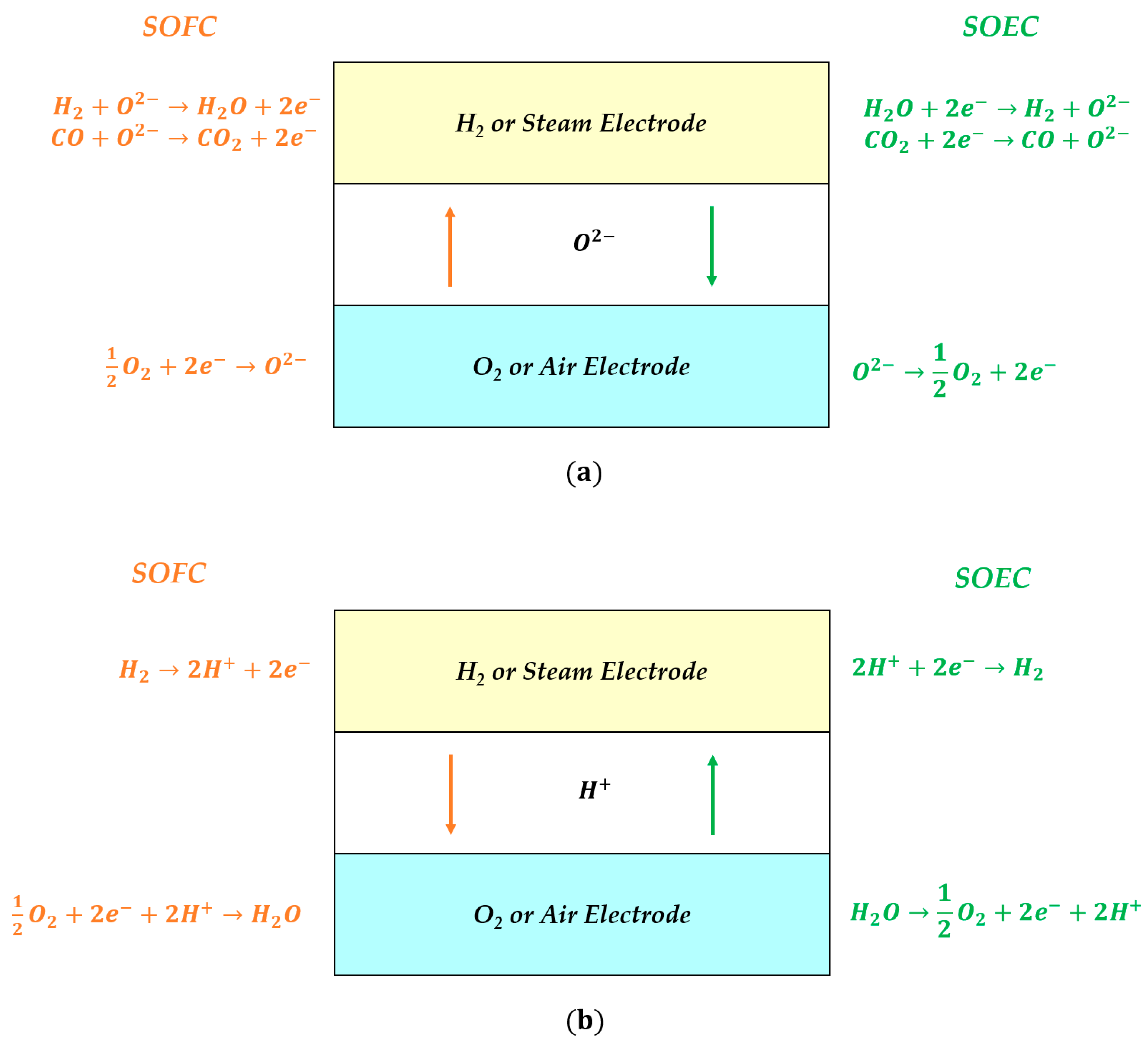
The common configuration is based on the anionic conductive electrolyte cell, where the charge carriers are oxygen ions; in this case, both H2/H2O and CO/CO2 redox reactions are possible (Figure 1a). In SOFC mode, the oxygen fed at the air electrode is reduced, generating O2− which migrates through the electrolyte to oxidise the hydrogen and/or the carbon monoxide at the hydrogen electrode side. The opposite mechanisms occur during co-electrolysis operation in SOEC. A quite new application consists of Protonic Ceramic Cells (PCCs), where hydrogen ions move inside the electrolyte permitting only the steam reaction path (Figure 1b). They are a quite promising alternative for rSOCs since they can work at temperatures ranging between 773 and 873 K (the anionic conductive electrolyte configuration requires 923 K at least). Despite these lower temperatures, both a high conductivity and a low activation energy are guaranteed. Moreover, the steam management is easier because water evolves only at the air electrode. Here, the different operating mechanism avoids the fuel dilution in fuel cell mode and a further separation step to purify hydrogen in electrolysis [30]. Nevertheless, PCC is not a mature technology yet, having low durability and not well-defined working conditions due to issues of material chemical stability [31]. In SOEC mode, some preliminary tests have also been carried out applying a hybrid solution, where the use of a mixed ionic electrolyte favours the simultaneous conduction of oxygen and hydrogen ions in the opposite directions. Since the water evolution can occur at both sides, feeding steam as an anodic and cathodic reactant permits the production of H2-rich and O2-rich mixtures at the steam and oxygen electrode, respectively. The comparison with other SOEC configurations shows better performance due to higher applied current densities at equal requested potential, resulting in an increase of hydrogen production. Also, durability tests performed until 60 h are promising; nevertheless, further tests are needed trying to increase the fed steam concentration [32].
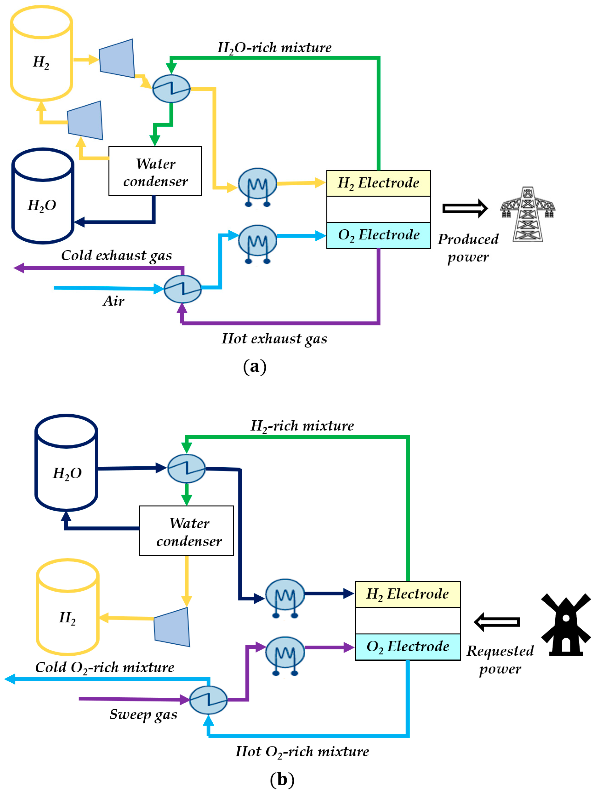
In the next paragraphs, the analysis focuses on cell behaviour considering only the H2 reaction path, which is the most common working condition. As shown by a schematic representation of the rSOC system (Figure 2) [17], the balance of the plant includes some upstream heat exchangers to reach high working temperatures, which also use the hot outlet streams to pre-heat reactants. In SOFC operation, an H2-rich mixture and air are usually fed to the cell, generating the requested power and producing water, then separated through the condenser and partially recycled (Figure 2a). In SOEC, an external load is requested, and the flows are inverted: the steam and the sweep gas (usually air, but also water is possible [33]) are supplied to the system, obtaining mainly hydrogen that is compressed at more than 200 bar [34] and is stored until its reuse in fuel cell operation (Figure 2b). Seawater could be directly fed to the electrolyser, reducing the cost of upstream separation units to purify water. Indeed, sea chlorine-based salts volatilise at temperatures higher than 1073 K, avoiding the risk of their deposition on electrode active sites. This is confirmed by preliminary experimental observations, where no serious contaminations were detected at the steam electrode [35]. Whereas, in low-temperature cells, some degradation mechanisms occur, such as the gradual formation of insoluble precipitates on the steam electrode surface and the chlorine production at the oxygen electrode if seawater is used as sweep gas [36].
However, in real applications, the intermittent electricity input and the variable power demand impose transients that could cause severe degradations. Changing the electric load, a considerable temperature gradient is formed between the inlet and outlet section due to cell thermal inertia (possible transients also in the order of hours as a function of the size [37]), provoking thermal-mechanical stresses due to rapid occurring peaks of temperature [38]. This issue is highlighted during reversible operation since the thermal behaviour varies between the exothermic fuel cell and the endothermic or exothermic conditions in electrolysis, making the system management more complex. Moreover, a further consequence of the current density increase in SOFC mode is the modification of fuel utilisation, which results in a reaction zone concentrated in the inlet cell area, leading to hydrogen depletion in the next cell portions [39]. A fine control system, able to maintain the cell behaviour in desired design constrains, is unavoidable in order to guarantee long-term performances in dynamic operation. Specific control loops have to regulate temperature and utilisation by tuning air and fuel flow rates, respectively. Otherwise, SOCs can be protected working with an excess of reactants at both the anodic and cathodic side; nevertheless, this provokes a larger energy consumption for the air blower and the steam production [40].
3. Performance Evaluation
A common key performance indicator is the characteristic curve, which represents the obtained voltage, V, as a function of applied current density, J (Figure 3), or, in other terms, as a function of the reaction rate according to the Faraday law for a single cell (Equation (1)):
where z is the charge number, F is the Faraday constant, N is the reacted molar flow rate of key reactant-product and A is the active area.
From a thermodynamic point of view, the equilibrium value, Veq, is derived from the Nernst equation knowing the working temperature and fed reactant compositions (Equation (2)):
where the first term considers the Gibbs free energy variation, ΔG, at cell working temperature, T, whereas the second takes into account the effective partial pressures, p, of reactants or directly their molar fractions, y (R is the ideal gas constant and pref is the reference pressure equal to 1 bar). This value represents the Open Circuit Voltage (OCV).
Nevertheless, when a load is applied, some overpotential phenomena occur due to different mechanisms, such as charge migration, gas diffusion and requested energy to overcome the activation barrier of reactions. Here, the voltage is penalised by obtaining a lower value for SOFC mode (i.e., less outlet power gain) and a higher one in SOEC mode (i.e., more inlet power demand). Equations (3) and (4) show the real cell potential considering different overpotential, Vp, terms in both operations (for a detailed description of the electrochemical kinetics formulation, refer to [41,42]):
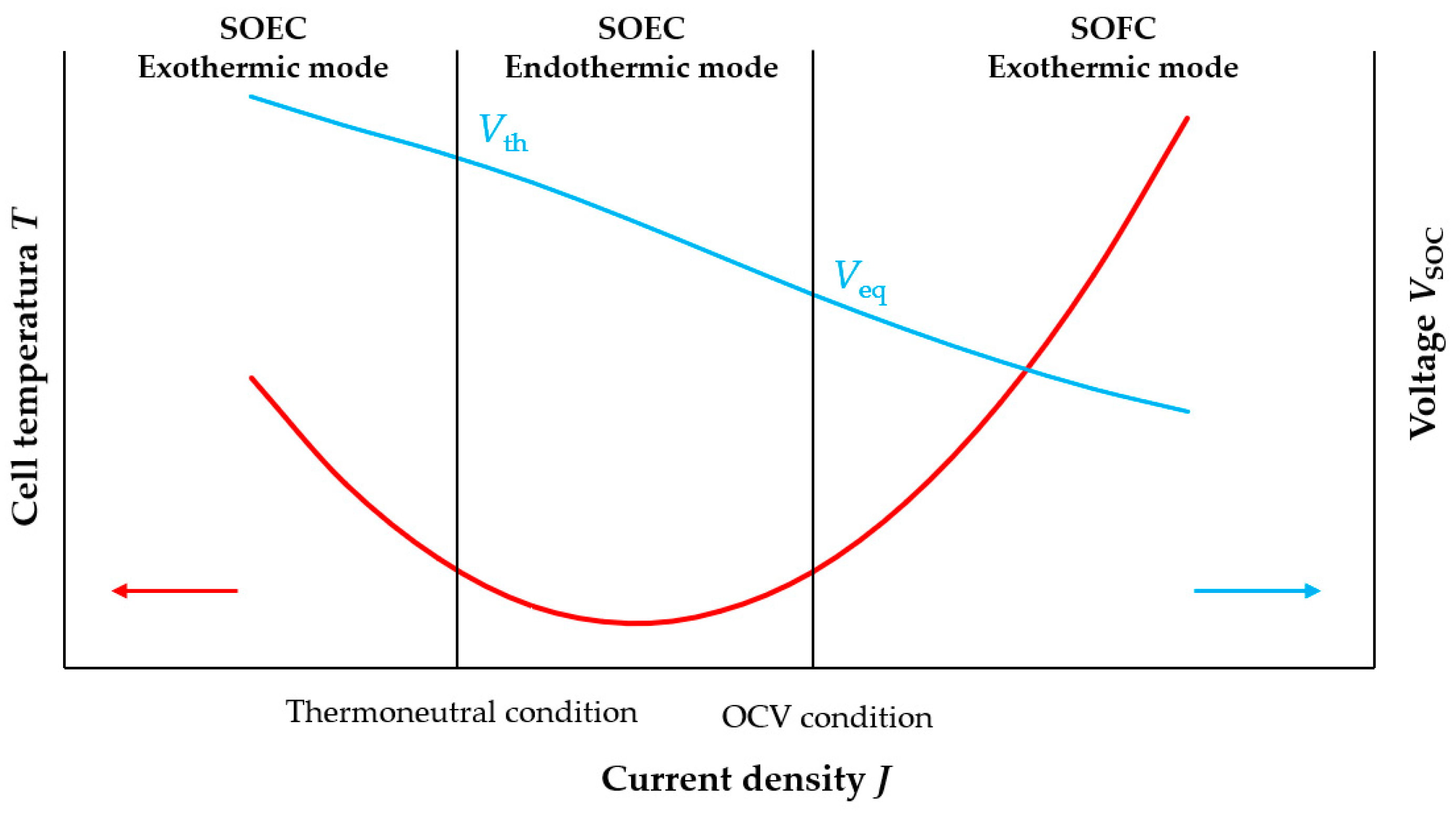
The cell thermal behaviour is strictly correlated to the specific operating point identified by a voltage-current density pair. Assuming to work in adiabatic conditions, during SOFC operation, the temperature always tends to increase due to both the exothermic reaction of hydrogen oxidation and the heat produced by occurred resistances through the Joule effect (Figure 3). Whereas, in SOEC mode, different situations are possible depending on the V-J operating point. Indeed, the water dissociation is an endothermic process which tends to reduce the temperature. On the other hand, some heat is generated due to the charge transfer, so the balance between these two effects defines the actual cell behaviour. The working point at which the thermal equilibrium is reached (i.e., no temperature variation occurs inside the system) represents the thermoneutral potential, Vth. Theoretically, this point is defined by enthalpy reaction, ΔH, which can be assumed as a constant value equal to 250 kJ mol−1, having a slow dependence on temperature (Equation (5)) [43]:
When the actual voltage is lower than the thermoneutral value, the system has effectively an endothermic behaviour, whereas if the measured value is higher than Vth, the Joule effect prevails, causing a temperature increase (Figure 3).
Focusing on specific cell performance, rSOCs are usually evaluated in terms of round-trip energy efficiency, ηrSOC, defined as the ratio between the energy obtained in fuel cell operation and the energetic consumption during electrolysis (Equation (6)) [44]:
For SOFC operation, the electric efficiency, ηSOFC,el, compares the outlet power, PSOFC,out, with the energy contained in the reacted hydrogen, NH2,r, referring to its lower heating value, LHVH2 (Equation (7)):
In other terms, Equation (7) can be rewritten as the ratio of the measured voltage on the theoretical one (i.e., thermoneutral voltage). Indeed, LHVH2 is substituted by the reaction enthalpy, ΔH, and, applying the Faraday law (Equation (1)), the consumed hydrogen is expressed as a function of the current density, J (Equation (8)):
Whereas the SOFC global efficiency, ηSOFC, has to also evaluate reaction selectivity, comparing the reacted fraction expressed through Faraday law with actual feed, NH2,feed (i.e., fuel utilisation value UH2) (Equation (9)):
Using the same definition for SOEC mode, the electrical efficiency, ηSOEC,el, is equal to the ratio between the power stored as hydrogen (H2 produced amount NH2,g for its lower heating value LHVH2) and the provided inlet power, PSOEC,in, or, in other terms, between the theoretical requested voltage and the actual provided value (Equation (10)):
According to this formulation, the SOEC electric efficiency results to be higher than 100% when the cell works in endothermic mode. Nevertheless, Equation (10) does not consider the whole actual used energy since some heat has to be provided to the cell in order to maintain the fixed design temperature. Here, the ηSOEC,el is corrected summing the thermal power, QSOEC, to inlet SOEC electric power (Equation (11)):
Assuming an isothermal and isobar cell behaviour, QSOEC derives from the difference between the heat demand of the electrolysis reaction and the heat generated by the Joule effect [45]. The specific requested heat, , is equal to the molar reaction enthalpy, ΔH, minus the energy provided to the system as specific electric work, . Expressing every term as voltages, the followed formulations are obtained for QSOEC and ηSOEC, respectively (Equations (12) and (13)):
This definition considers only the cell performance, neglecting other system energy exchanges. In order to obtain a more realistic value, as first approximation, the heat to generate steam is also added, which has a relevant influence on global energy consumption. Equation (14) shows the electrolysis system efficiency, ηSOEC,system, considering the requested thermal power to produce steam at the desired operating temperature, Qsteam:
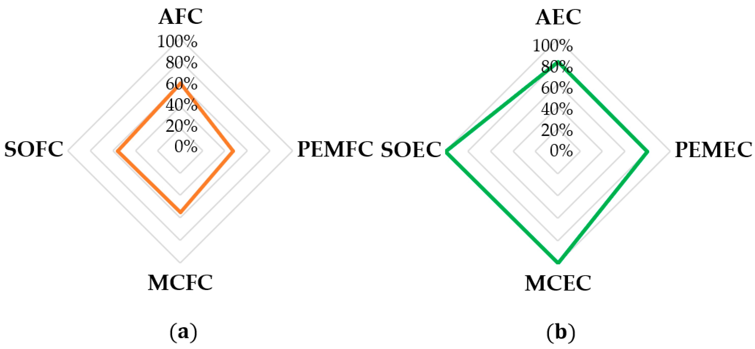
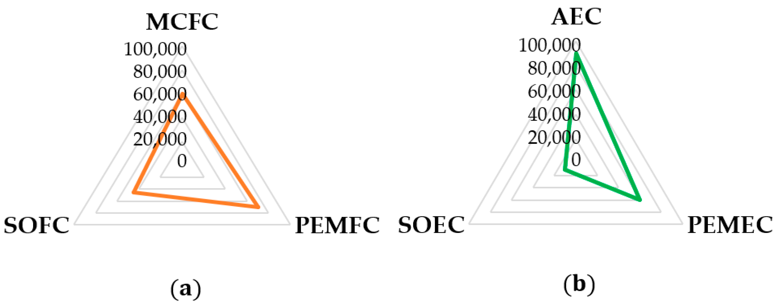
In both fuel cell and electrolysis operation, high-temperature solid oxide cells usually have a good efficiency since the kinetics depends on thermally activated processes [46]. In fuel cell mode, the common efficiency, ηSOFC, is around 50–60%, nevertheless, 70% is also obtained in specific operating conditions. This result is comparable with other electrochemical cell types (Figure 4a) [27] and in some cases, higher than available power systems, such as simple cycle turbine generators (35%), combined cycle turbine generators (60%) [47] and diesel engines (45%) [48], as well as renewable-based solutions such as photovoltaics (20%) [49] and wind turbines (35–45%) [50]. On the other hand, working commonly at thermoneutral point, solid oxide and molten carbonate electrolysers reach 100% of ηSOEC, whereas alkaline and polymer electrolyte membrane cells have a performance of about 80% in main operation cases (Figure 4b) [51,52]. Considering the whole system energy requested, AEC and PEMEC cannot overcome the 70% as ηSOEC,system, whereas SOEC also reaches 80%, providing the requested energy as both heat and electricity [14].
A more detailed comparison of different available technologies is shown in Table 1. Looking at fuel cell operation, SOFCs result to be quite competitive in terms of cell efficiency; nevertheless, they are characterised by a lower power density value and quite higher capital costs compared to low-temperature design [53,54]. Whereas, SOECs have lesser available production rates but a higher system efficiency and a smaller energy consumption, which allows for halving the electrolysis power request with respect to low-temperature cells in the best working conditions [12,52,55]. Considering the reversible operation, SOCs guarantee to have a single unit able to operate in both modes differently from other cell configurations where some material limits occur. Moreover, they also are more favourable than commercially available energy storage systems, showing an energy density of 500–3000 kWh m−3 with respect to 0.5–80 kWh m−3 of mechanical storage, 80–500 kWh m−3 of thermal storage and 50–500 kWh m−3 of batteries [7], where the volume of the storage device includes the volumes of the energy storing element, accessories and supporting structures, as well as the inverter system [10].
Another relevant parameter to evaluate rSOC reliability is its actual durability. Considering fuel cell mode, different targets are fixed depending on specific applications. For the automotive field, a 5000 h durability is requested, whereas the combined heat and power systems have to reach the 60,000 h operation for residential and light commercial scales (1–25 kW power capacity), until a value of 80,000 h at the large industrial level (100 kW–3 MW) [56]. High-temperature fuel cells usually overcome 40,000 h: tests on MCFCs have shown 60,000 h of continuous operation [57], whereas about 45,000 h operation is the actual SOFC level [7]. Low-temperature fuel cells are usually applied in the transport sector, for instance, AFC operation can reach 8000 h of operation, exceeding the requested target [58]. Lifetime of PEMFC is longer: it achieves a 70,000 h operation in micro-combined heat and power plants (Figure 5a) [56]. Focusing on electrolyser cells, long-lasting performances are obtained in AEC and PEMEC configurations, resulting in 90,000 and 60,000 h, respectively [12]. High-temperature technologies are less competitive, since the first SOEC applications consist of a 10,000 h operation (Figure 5b) [12], whereas MCECs have been mainly tested at the lab scale for some thousands of hours, also trying in reversible mode [59].
Since the system usually works at a constant current density, the voltage variation during the operation period expressed in hours, t, is the main indicator to estimate the actual system durability. The Degradation Rate (DR) is expressed as the percentage variation between the measured voltage, VSOC,t, and its initial value, VSOC,0, normalised to the starting point. Commonly, 1000 h are assumed as the reference time step (Equation (15)). Hence, V decreases in SOFC and increases in SOEC.
In SOFC mode, DR is around −0.25 V% kh−1, guaranteeing a 40,000 h operation; nevertheless, the next target is −0.11 V% kh−1 to reach 60,000 h [60]. SOEC degradation effects are usually more severe, resulting in a higher degradation rate of +0.5 V% kh−1 [15]. Considering the cell reversible operation, different results were obtained in terms of performance depending on specific testing conditions. Making rSOCs work for some thousands of hours, the DR of electrolysis mode is doubled, also reaching +1.2 V% kh−1; in fuel cell mode, the degradation rate is higher, measuring a reduction of −3 V% kh−1. The main causes of this worsening are due to thermomechanical stresses, which induce the crack formation and further delamination, as confirmed by the internal resistance change [61]. However, if a proper cycling operation is studied, the microstructural deterioration can be inhibited. According to experimental observations, the major degradation in SOEC operation is provoked by high internal oxygen pressures at the electrolyte–oxygen electrode interface. Indeed, the storage of O2 bubbles induces the formation of nanosized pores which grow until the complete separation of grains. Before this irreversible deformation, there is an incubation period when the critical level of the stress is not yet reached. Fixing the time of each cycle shorter than the incubation period, it is possible to avoid a severe degradation by releasing the pressure and healing grain boundaries in fuel cell mode. Indeed, in this operation, the gas partial pressure decreases, consuming oxygen in the redox reaction, and moreover, the temperature rise favours material re-sintering processes [62].
4. Influence of Operating Conditions on Performance
The most challenging aspect of rSOC operation is the possibility to reach a high round-trip energy efficiency by using a single bifunctional unit. According to the European Association for Storage of Energy (EASE), the requested efficiency target is about 80% to be competitive on the market [63]. The obtained efficiency is strictly dependent on operating conditions which have a direct link to electrochemical kinetics. From a thermodynamic point of view, the use of higher temperatures means a lower equilibrium voltage considering the strong decrease of Gibbs free energy (Equation (2)), which favours the electrolysis, reducing the needed input power, and worsens the fuel cell operation, obtaining a minor outlet electricity value. Looking at the actual reversible cell voltage, the different resistances are reduced since all occurring mechanisms are thermoactivated, so both charge migration and reaction development are improved. Nevertheless, a higher temperature can induce some degradation processes, resulting in lower lifetime [64], in addition to a complex control system when a dynamic operation occurs. For these reasons, in the last years, a common target was the temperature decrease by improving materials and system design. The intermediate-temperature cells, usually working from 923 and to 1073 K at most, have had a relevant spread in the last decade [25]. Considering the pressure, in this case, the thermodynamic reaction is favoured by increasing its value in fuel cell operation and is slowed during electrolysis, as shown by its positive dependence in the last term of the Nernst equation (Equation (2)). However, a higher pressure simplifies the integration with other units, indeed the hydrogen is pressurised to be stored and used as transport fuel (until maximum 700 bar for fuel cell vehicles [20]); moreover, several downstream chemical synthesis reactors are pressurised. On the other hand, working in pressure is a more dangerous condition; indeed, the pressure differences between hydrogen and air electrode side should be minimised in order to avoid gas crossover. The current pressures of the stack range between 1 and 25 bar [15]. Regarding the operating compositions, if a reversible operation is analysed, steam electrolysis and hydrogen-fed fuel cell are the most common configurations. In SOFC mode, wet hydrogen is supplied since the water has a positive effect, reducing polarisation losses [65]. Moreover, different microstructural changes characterise wet and dry feed: a higher degradation rate is detected in the dry hydrogen case for some electrode materials [66], whereas steam with low hydrogen percentage is used in electrolysis processes. Moving to air electrode, dry air is the most common feed in both SOFC and SOEC. Pure oxygen would permit to have a higher cell voltage, useful in fuel cell mode, nevertheless additional costs are requested. As sweep gas, steam is proposed as an alternative for the electrolysis, simplifying the system using the same reactant at both sides. The cell performance is also influenced by the applied electric load: a higher current density means faster reaction kinetics and a better reactant conversion. Nevertheless, in these stressed working conditions, there is always the risk of fuel starvation.
Focusing on the H2 reaction path, SOFC and SOEC behaviour is studied through SIMFC/SIMEC at common working conditions, underlining how the changes of current density and hydrogen/steam utilisation influence the trend of efficiency and therefore detecting the optimised operation (Table 2).
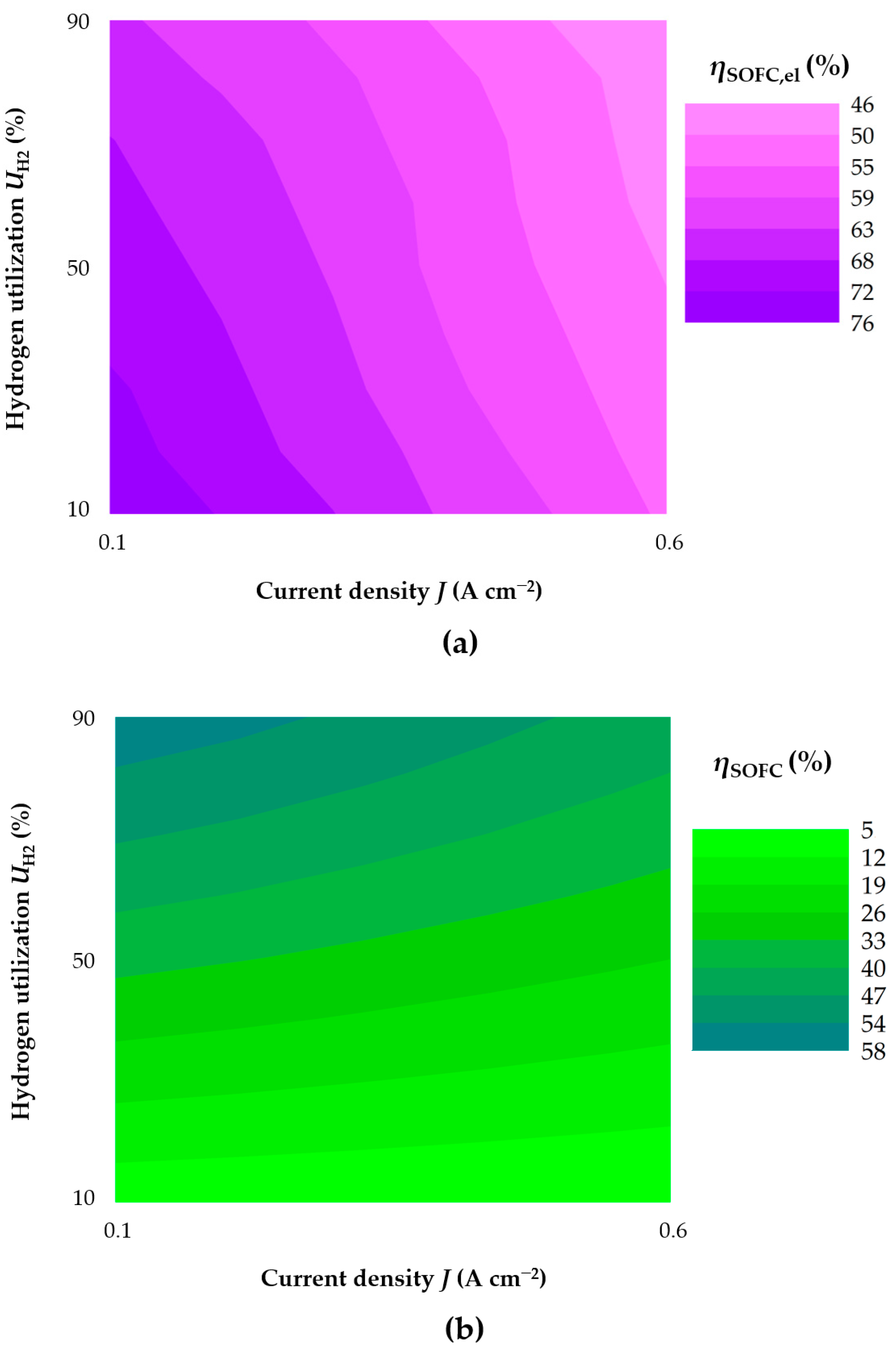
For SOFC operation, the goal is the increase of the produced outlet power, a condition obtainable by increasing the current density. Looking at ηSOFC,el, higher values characterise low electric loads because of the small amount of reacted hydrogen. When the current density is fixed, the increase of utilisation value UH2 also worsens the performance due to voltage reduction, which is caused by minor reactant concentrations on the cell plane. As Figure 6a shows, the best efficiency is about 76%, reached at small J and UH2. Nevertheless, looking at ηSOFC, very low values are detected when a low hydrogen utilisation is imposed; considering actual fuel feed, the maximum equal to 58% is reached at low J but high UH2 (Figure 6b). A compromise consists of working at 0.3–0.4 A cm−2, where ηSOFC,el and ηSOFC are around 60% and 50%, respectively. Under this load and assuming −0.25 V% kh−1 as DR, the voltage variation induced by degradation provokes an efficiency reduction of about 2.5% after 10,000 operation hours. A decrease of 10% is detected only after 40,000 h, guaranteeing a quite good long-term performance.
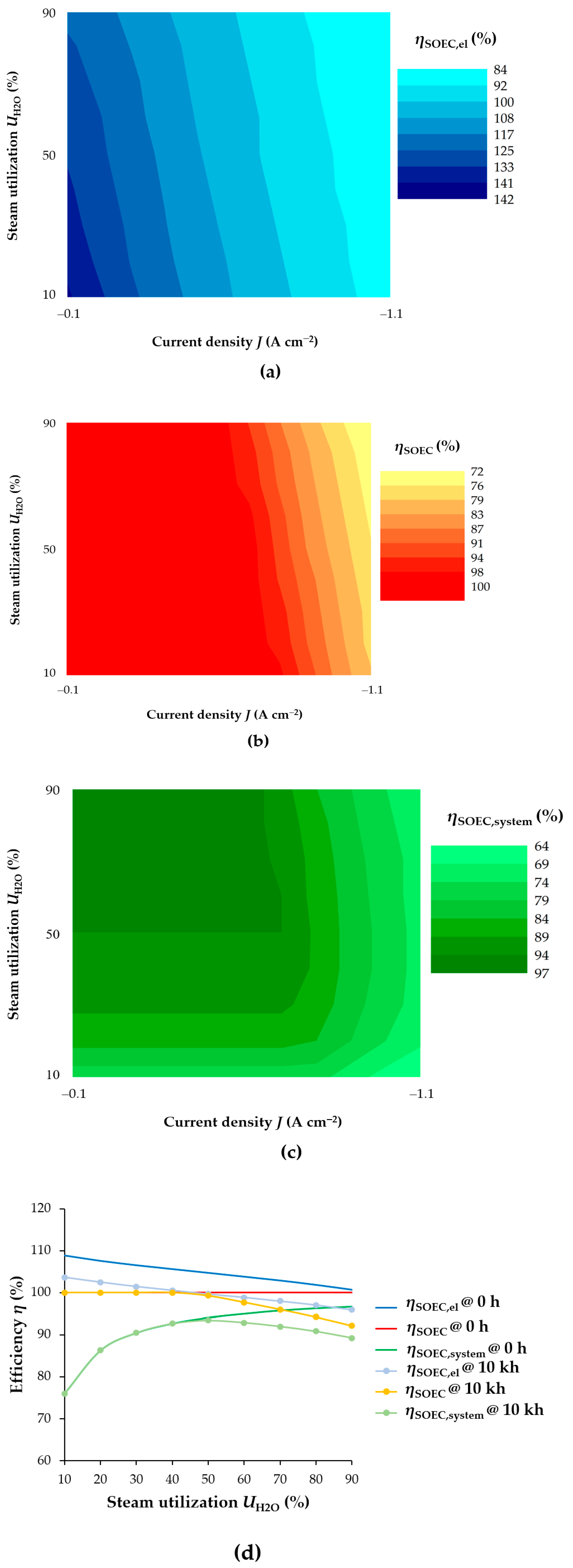
On the other hand, for SOEC mode with dry air as sweep gas, the efficiency dependence on working conditions is strictly correlated to cell thermal behaviour (i.e., endothermic, thermoneutral or exothermic operation). Changing the current density, J, and the steam utilisation, UH2O, different trends are detected above and below the thermoneutral point. As shown in Figure 7a, the electric efficiency decreases when the current density rises at a fixed conversion due to higher requested inlet powers. The increase of utilisation also worsens the performance due to the reactant composition change, which provokes an upper cell voltage. Below the thermoneutral point (around −0.6 and −0.7 A cm−2 for these simulated working conditions), the ηSOEC,el exceeds 100% because VSOEC is less than Vth, whereas for high electric loads, the efficiency has a lower number, reaching 84% as the minimum. Considering the ηSOEC (Figure 7b), the left section of the map has a fixed value of 100% since all the provided heat is actually used to maintain an isothermal behaviour, whereas overcoming the thermoneutral point, the efficiency starts to decrease because part of the heat produced through the Joule effect is dissipated. At UH2O increase, the thermoneutral working point shifts slightly at lower current densities since less water is requested to satisfy the fixed conversion, resulting in higher voltages. In the case of ηSOEC,system (Figure 7c), the 100% value is never obtained: the best working point of 96% is detected at UH2O equal to 90% and low current densities. Indeed, in those conditions, most produced steam is converted into hydrogen without an excessive inlet electric power. Moreover, working below the thermoneutral point, there is not a thermal energy surplus. Considering values of tension higher than Vth under a fixed electric load, a maximum profile is evaluated since the UH2O increase provokes a reduction of the requested feed water. In the first step, the efficiency improves since the contribution of thermal power for steam production prevails (i.e., less water to be heated), whereas for higher utilisations, the dissipated energy due to charge transfer is not more negligible, resulting in a reduction of global system performance. Therefore, optimal conditions are obtained at low current density and high steam utilisation (the left-top zone of Figure 7c). In order to guarantee a relevant hydrogen production, the boundary working point is at an electric load of about −0.6 A cm−2, with UH2O equal to 90%, where SOEC operation is near the thermoneutral condition favouring an efficient cell thermal balance. Assuming a continuous operation at −0.6 A cm−2 with a degradation rate of +0.5 V% kh−1, the system performance worsens, as the comparison between the nominal condition and after 10,000 operation hours shows (Figure 7d). The electric efficiency has a reduction of about 5% in all utilisation ranges. The voltage increase due to degradation shifts the thermoneutral point so that ηSOEC is no longer always equal to 100%, as in the cases of UH2O higher than 50%. After this value, SOEC works in exothermic mode, resulting in a maximum profile for ηSOEC,system, differently from the simulation at time equal to zero when the effect of steam power prevails, justifying the constant increase with steam utilisation rise.
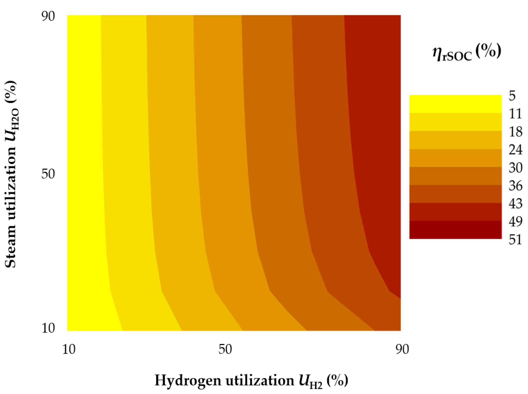
In nominal operation, the round-trip energy efficiency (Equation (6)) can be evaluated as the product between ηSOFC and ηSOEC,system. As an example, in Figure 8, the rSOC performance is shown varying hydrogen and steam utilisation at optimised current density values equal to 0.3 and −0.6 A cm−2 for SOFC and SOEC, respectively. The maximum identified ηrSOC value is 51% at high UH2 and UH2O (the right-top corner of the map), whereas the minimum reached in the opposite condition is 5% (the left-bottom corner of the map). Indeed, at fixed fuel cell operation, the electrolysis performance is mainly dependent on thermal power requested to heat the steam, since the cell works near the thermoneutral point. The decrease of UH2 worsens the efficiency because a lower hydrogen amount is actually used during SOFC operation.
5. Technology Readiness Level
Differently from other cell technologies, SOCs have had a quite recent development, showing to be promising solutions due to their good efficiency and lower material costs. Initially, the research focused mainly on fuel cell mode, which has already reached the first commercial stationary applications, whereas large-scale prototype plants are being built to produce hydrogen or other useful fuels through SOECs. Considering the reversible operation, some issues have to be overcome before making these cells competitive on the energy market; above all, improvements of thermal management strategies should be introduced in order to reduce possible stresses by moving from electrolysis to fuel cell mode and vice versa. Moreover, a further fundamental step is the evaluation of delay due to the switch between two operations and the resulting needed time to again reach the steady-state conditions. Table 3 summarises the Technology Readiness Level (TRL), a useful classification to label the commercial feasibility of the solid oxide cell use in different possible application fields.
The main SOFC application consists of residential micro-co-generators in the scale of 0.75–1.50 kWel, reaching a thermal power of 1 kW as a maximum. PEMFCs are also successfully applied in the 1–5 kWel residential field, showing good performance with a very long lifetime (up to 70,000 h); nevertheless, they can provide less thermal energy, and moreover, they require pure hydrogen as feed [67]. These limits have been partially solved through the introduction of high-temperature PEMFC working at 393 K, which allows for reducing CO adsorption on active sites and therefore simplifies the requested gas pre-treatments [70]. Whereas, this issue is not present in SOFC configuration, which is usually fed continuously by common available fuels such as natural gas or liquid petroleum gas, exploiting internal reforming reactions possible by high working temperatures [71]. The stacks are connected steadily to the grid in order to guarantee a regular operation and avoid thermal cycles, which are causes of degradation. The household requirement is always satisfied through the integration with the electricity grid that permits to handle the peaks of demand and to sell the non-auto-consumed energy. The global energy efficiency is about 88–89% considering both electricity and heat production [72,73]. In terms of durability, a SOFC with 1.5 kWel capacity was tested for more than 20,000 h, showing a reduction of the net electric efficiency from 60% to 58%. Here, the estimated degradation rate is about −0.2 V% kh−1 [74]. Considering large-scale plants, several installations were realised. For instance, 250 kWel was installed upstream of a micro-gas turbine to improve the system global performance by also exploiting the energy present in hot-exhausted gases [75]. Higher capacities are already available: one of the main installations was projected in Japan, consisting of 1.2 MWel able to provide about half of the building electricity demand [76]. However, these sizes are still far from larger industrial power systems where MCFCs are mainly used: for instance, in Korea, a 58 MWel MCFC plant is able to provide the electricity to satisfy 140,000 households [53].
In the automotive field, SOFCs have been proposed as Auxiliar Power Units (APUs) for buses or high–medium-duty vehicles by using conventional road diesel fuel. During standstill, they provide the requested electricity for A/C, TV, refrigerator, personal computer and so on. A preliminary prototype installation was performed in the framework of the DESTA project: a 2.9 kWel system was tested for a more than 2500 km trip evaluating the cell performance, despite occurring vibrations and other external inputs which can deteriorate the cell, and the estimated APU efficiency was around 29%. In this case, SOFC does not work in continuous mode, so the start-up phase takes about 70 min before reaching the nominal working conditions [77]. Next studies aimed at evaluating the feasibility of SOFC use as 5 kWel APU also for passenger cars [78]. Due to quite long start-times, they are not suitable for fuel cell electric cars, where 100 kWel PEMFCs are successfully applied, consuming around 0.8 kg of hydrogen per 100 km with an expected lifetime of 20–25 years [79]. The railway sector is also dominated by low-temperature fuel cells: 300 kWel PEMFCs are commonly used in a hybrid solution with batteries [80]. Whereas a more feasible SOFC application field results to be a fuel cell power ship, where a 100 kWel unit was already successfully tested [81].
Differently from SOFC technology already available on the market, the solid oxide electrolysis operation is experimenting the initial attempts to be competitive and to substitute the widely used low-temperature systems. The recent results are quite promising since the estimated SOEC energy consumption is about 3.7 kWh Nm−3 (H2), definitely lower than AEC and PEMEC with characteristic values ranging between 4.8 and 4.7 kWh Nm−3 (H2) [69]. Moreover, the integration with renewable sources helps to overcome the major limit to their large-scale spread consisting in high operation costs due to the electricity prize. The main application of the steam electrolyser is the chemical production for small size plants which require high-purity hydrogen, such as metal processing, food factory and synthesis of some polymers (excluding the unique Norwegian installation of MW-size alkaline configuration for ammonia production, with a daily capacity of 1000 tons, requesting a 397 MW inlet power [82]).
Solid-cell electrolysers can operate in co-electrolysis mode, making them suitable to produce traditional fuels from renewable energy sources. Power to Methane plants have as the main outcome the substituted natural gas with all the functionalities of conventional natural gas, so engines and power generators do not require any modifications. Moreover, CO2 use into the methanation permits to see this gas as a renewable carbon source instead of a process residue in light of a circular economy approach. Several demonstration plants were also proposed using low-temperature cells, yet in that case, the electrolysis produces only pure hydrogen and not directly a syngas, requiring a different system design [83]. The EU project HELMETH developed a SOEC unit thermally coupled with a downstream methanation reactor in order to optimise the internal heat exchange [84]. The system has a power capacity of 10 kWel, with an energy consumption of 3.37 kWh Nm−3. The global conversion efficiency from renewable electricity to methane is higher than 85%, making this application more convenient than the basic steam electrolysis. This higher performance is also obtained by using a pressurised system at about 10–15 bar; nevertheless, a proper strategy has to be introduced in order to minimise the internal pressure gradient, which causes dangerous mechanical stresses. The Power to Liquid approach is another interesting route that allows the synthesis of both gasoline and diesel. Here, an ambitious project has been launched by Norsk e-Fuel which is planning to build the first European commercial plant for a hydrogen-based 100% renewable jet fuel [85]. The pilot unit would start its operation in 2023 with a yearly production capacity of 10 million litres, whereas the complete commercial level plant should be completed by 2026, reaching the target of 100 million litres produced through a MW-scale solid oxide electrolyser.
A quite new possible SOEC application is the use for the ammonia synthesis substituting the traditional process consisting in an alkaline electrolysis coupled with the air separation unit [68]. Indeed, the mixture N2-H2 is directly obtained by the solid oxide cell that works as an oxygen separator membrane, simplifying the plan and reducing high-energy costs due to the air separation step. Both water and air are fed to the steam electrode, where the oxygen is burnt by a part of produced hydrogen providing water for the electrochemical reaction. Through electrolysis, the derived oxygen ions migrate to other electrodes, resulting in O2 segregation from nitrogen, which remains at the steam electrode side. A scale prototype was tested by using a 50 kWel SOEC, whereas the first commercial applications should be ready by 2030, with an estimated NH3 production capacity of about 7.2 MWh ton−1 rather than 7.8 MWh ton−1 of the current state-of-the-art technology.
High-temperature solid oxide cells have also been proposed as stand-alone units for CO supply on-site through dry electrolysis operation. Feeding pure CO2 provides both CO- and O2-rich streams with an efficiency higher than 90% compared to 27–54% of low-temperature designs [52]. Indeed, their main limit is the poor selectivity for CO production working into an aqueous solution with ion exchange membranes, where the competitive H2 evolution reaction is favoured. Moreover, the carbonate formation easily occurs, resulting in an excessive voltage request and CO2 losses [86], while the SOEC selectivity is equal to 100%, since water is not necessary for the process evolution. Thanks to these several strong points, dry electrolysis is become a promising alternative to traditional reforming for small-scale applications in the range of 10–300 Nm3 h−1. The first commercial application called eCOs (electrolytic CO solution) was installed in 2016 and it is currently in operation in the USA with a nominal capacity of 12 Nm3 h−1 [87]. However, higher sizes are possible by using a modular design: the next target is the building of plant able to produce 96 Nm3 h−1 with an expected energy consumption of 3.44 kWh Nm−3 (CO) (a value quite comparable to the steam electrolysis process) [88].
A more niche sector is the use of SOEC for the pure oxygen production, which is an interesting application in the aerospace field. Indeed, the Martian atmosphere has a high CO2 level that could become a prime resource for the oxygen extraction, providing about ¾ of human needs for the exploration of the Red Planet. Moreover, the reversible SOC operation would also allow the on-site power production [89]. During the ongoing Mars 2020 mission, NASA has projected specific tests to check the feasibility of SOC applications on Mars [90]. MOXIE experiments will aim at demonstrating the 0.3 kWel SOEC use as in-situ resource utilisation technology able to produce oxygen from Martian atmosphere. Considering specific environmental features, the cell operation will be optimised, changing working temperature, applied voltage and CO2 inlet flow rate with a final target of 2.3 kg h−1 oxygen generation.
Considering different tested and in-operation systems, Table 4 summarises the current development for both SOFC and SOEC technology.
Finally, considering reversible solid oxide applications, some prototypes are in operation to evaluate the effective reaching efficiency. In 2015, the world-first fully integrated rSOC system was connected to the Southern California Edison power grid [69]. Supplied by renewable power, the electrolyser produced hydrogen, feeding the water provided by a co-located steam source, but also seawater was tested after a desalination step. H2 was compressed and stored in a commercial gas storage tube with a price of about 25–30 € kWh−1. Taking only a few minutes, the system switched into fuel cell mode in order to provide the requested supplementary power during peak hours. Final tests were performed at the U.S. Navy base on the island of Oahu, Hawaii, connecting the system to the island microgrid [91]. Two modules of 100 kWel guaranteed a hydrogen production of 50 Nm3 h−1 with a system efficiency higher than 80%, whereas SOFC size was 50 kWel characterised by 60% performance. The obtained round-trip energy efficiency was about 45%. In the framework of the GrInHy project, the SOC technology paired with renewable sources was recently installed in a German steelwork [69]. It consists of 6 modules with 48 stacks each, guaranteeing a high flexibility of system operation. The electrolysis mode with 150 kWel nominal capacity is able to produce 40 Nm3 h−1 of hydrogen, reaching a system efficiency of 84%, yet its operation can be overloaded until 200 kWel, becoming the SOEC application with the highest capacity worldwide. The plant also works in reversible operation, switching into fuel cell mode if there are peaks into electricity demand. The same unit is fed by process gases with high hydrogen purity level or by directly natural gas, obtaining an efficiency of about 50%. Despite these promising examples, different issues still have to be overcome before rSOC commercial launch. Beyond a rough knowledge of cell behaviour and degradation switching from fuel cell to electrolysis mode, also the balance of plant requires a careful optimisation, above all looking at thermal management due to different operation succession as well as considering reactant storage to decrease the complete system size. The integration with renewable sources is an interesting application to reduce external energy costs, however it is still necessary to study how to connect the rSOC unit to existing grids in order to minimise energy losses and always satisfy the user demand, therefore choosing the most suitable plant size. The possibility to use and produce common fossil fuels can incentivise the spread of these technologies with respect to low-temperature cells due to the absence of a proper hydrogen distribution system. On the other hand, more clarifications are required to guarantee the achievement of an effective circular approach, where all outlet products are reused as inputs in the system, leading to issues of CO2 availability and capture.
6. Conclusions
Solid oxide cells are promising technologies due to better performance compared to low-temperature designs: high efficiency, lower requested electricity consumption in electrolysis mode and flexible feeding to fuel cell are only some main advantages. Nevertheless, one of their strong points is the possibility to work in reversible operation so that a single unit allows for both energy storage and generation. Their spread is further incentivised through the integration with renewable sources, which permits to have a complete green power plant aiming at the achievement of zero-energy building and carbon neutrality targets. SOFC co-generation plants have already been launched on the market with the first MW-sized installed capacities, whereas several hundreds of residential-scale units are in operation. Considering SOEC technology, different pilot plants were built in real field applications, exploiting this technology for high-purity chemical production: hydrogen from water and carbon monoxide from carbon dioxide, but also ammonia and conventional fuels using the produced syngas as an intermediate. Nevertheless, its most challenging application is as an alternative energy storage unit, showing a higher energy density and several possible life-cycles. In view of a smart grid strategy, the reversible operation allows for both generation and use of energy in situ, reducing the electricity costs and simplifying the grid. System performances are usefully evaluated referring to the efficiency, strictly dependent on applied working conditions. According to performed sensitivity analysis for a single solid oxide cell with 100 cm2 active area, the optimised cell performances should be a compromise between high efficiency and energy-gas production. Another relevant index for the system behaviour estimation is the degradation rate in view of long-lasting cell applications. Fixing high reactant utilisations and the current density equal to 0.3 and −0.6 A cm−2, the obtained efficiencies are about 52% for SOFC mode and 96% for SOEC mode. Nevertheless, if the cell works for 10,000 h, these values will be reduced by about 2.5% and 8%, respectively. Considering the reversible operation, the obtainable round-trip energy efficiency results to be about 50% at nominal conditions, whereas further detailed studies are needed to evaluate actual system performance during the time, since occurring microstructural changes have not been well-defined yet. Indeed, both improvements and deteriorations of SOC behaviour were detected depending on specific tested conditions and cycle time.
Author Contributions
Conceptualisation, F.R.B. and B.B.; methodology, F.R.B. and B.B.; software, F.R.B.; writing—original draft preparation, F.R.B.; writing—review and editing, F.R.B. and B.B. All authors have read and agreed to the published version of the manuscript,
Funding
The present research work has received funding from the Italian Ministry of Education, Universities and Research, MIUR, as a Project of National Interest, PRIN 2017F4S2L3.
Institutional Review Board Statement
Not applicable.
Informed Consent Statement
Not applicable.
Data Availability Statement
Not applicable.
Conflicts of Interest
The authors declare no conflict of interest.
Nomenclature
| A | Active area (cm2) |
| DR | Degradation Rate (V% kh−1) |
| F | Faraday constant (C mol−1) |
| ΔG | Gibbs free energy variation (J mol−1) |
| ΔH | Reaction enthlapy variation (J mol−1) |
| J | Current density (A cm−2) |
| LHV | Lower Heating Value (J mol−1) |
| N | Molar flow rate (mol s−1) |
| P | Electric power (W) |
| p | Pressure (bar) |
| Q | Thermal power (W) |
| Molar specific heat (J mol−1) | |
| R | Idel gas constant (J mol−1 K−1) |
| T | Temperature (K) |
| t | Time (h) |
| U | Reactant utilisation (%) |
| V | Cell voltage (V) |
| Molar specific electric work (J mol−1) | |
| y | Molar fraction (-) |
| z | Charge number (-) |
| Greek letters | |
| η | Efficiency (%) |
References
- News European Parliament. What is Carbon Neutrality and How Can It be achieved by 2050? Available online: https://www.europarl.europa.eu/news/en/headlines/society/20190926STO62270/what-is-carbon-neutrality-and-how-can-it-be-achieved-by-2050 (accessed on 18 November 2020).
- Lindsey, R. Climate Change: Atmospheric Carbon Dioxide. Available online: https://www.climate.gov/news-features/understanding-climate/climate-change-atmospheric-carbon-dioxide (accessed on 18 November 2020).
- European Commision. A European Green Deal Striving to Be the First Climate-Neutral Continent. Available online: https://ec.europa.eu/info/strategy/priorities-2019-2024/european-green-deal_en (accessed on 18 November 2020).
- EUROSTAT. Shedding Light on Energy in the EU. A Guided Tour of Energy Statistics. Available online: https://ec.europa.eu/eurostat/cache/infographs/energy/index.html (accessed on 18 November 2020).
- Rahman, M.W.; Hossain, M.S.; Aziz, A.; Mohammedy, F.M. Prospect of Decentralized Hybrid Power Generation in Bangladesh Using Biomass, Solar PV & Wind. In Proceedings of the 3rd International Conference on the Developments in Renewable Energy Technology (ICDRET), Dhaka, Bangladesh, 29–31 May 2014. [Google Scholar] [CrossRef]
- Magrassi, F.; Rocco, E.; Barberis, S.; Gallo, M.; Del Borghi, A. Hybrid Solar Power System versus Photovoltaic Plant: A Comparative Analysis through a Life Cycle Approach. Renew. Energy 2019, 130, 290–304. [Google Scholar] [CrossRef]
- Venkataraman, V.; Pérez-Fortes, M.; Wang, L.; Hajimolana, Y.S.; Boigues-Muñoz, C.; Agostini, A.; McPhail, S.J.; Maréchal, F.; Van Herle, J.; Aravind, P.V. Reversible Solid Oxide Systems for Energy and Chemical Applications—Review & Perspectives. J. Energy Storage 2019, 24, 100782. [Google Scholar] [CrossRef] [Green Version]
- Luo, X.; Wang, J.; Dooner, M.; Clarke, J. Overview of Current Development in Electrical Energy Storage Technologies and the Application Potential in Power System Operation. Appl. Energy 2015, 137, 511–536. [Google Scholar] [CrossRef] [Green Version]
- Hadjipaschalis, I.; Poullikkas, A.; Efthimiou, V. Overview of Current and Future Energy Storage Technologies for Electric Power Applications. Renew. Sustain. Energy Rev. 2009, 13, 1513–1522. [Google Scholar] [CrossRef]
- Chen, H.; Cong, T.N.; Yang, W.; Tan, C.; Li, Y.; Ding, Y. Progress in Electrical Energy Storage System: A Critical Review. Prog. Nat. Sci. 2009, 19, 291–312. [Google Scholar] [CrossRef]
- Díaz-González, F.; Sumper, A.; Gomis-Bellmunt, O.; Villafáfila-Robles, R. A Review of Energy Storage Technologies for Wind Power Applications. Renew. Sustain. Energy Rev. 2012, 16, 2154–2171. [Google Scholar] [CrossRef]
- Schmidt, O.; Gambhir, A.; Staffell, I.; Hawkes, A.; Nelson, J.; Few, S. Future Cost and Performance of Water Electrolysis: An Expert Elicitation Study. Int. J. Hydrogen Energy 2017, 42, 30470–30492. [Google Scholar] [CrossRef]
- Paul, B.; Andrews, J. PEM Unitised Reversible/Regenerative Hydrogen Fuel Cell Systems: State of the Art and Technical Challenges. Renew. Sustain. Energy Rev. 2017, 79, 585–599. [Google Scholar] [CrossRef]
- Böhm, H.; Zauner, A.; Goers, S.; Tichler, R.; Kroon, P. Innovative Largescale Energy Storage Technologies and Power-to-Gas Concepts after Optimization. D7.5: Report on Experience Curves and Economies of Scale. Available online: https://www.storeandgo.info/fileadmin/ downloads/deliverables_2019/20190801-STOREandGO-D7.5-EILReport_on_experience_curves_and_economies_of_scale.pdf (accessed on 30 November 2020).
- Hauch, A.; Küngas, R.; Blennow, P.; Hansen, A.B.; Hansen, J.B.; Mathiesen, B.V.; Mogensen, M.B. Recent Advances in Solid Oxide Cell Technology for Electrolysis. Science 2020, 370, eaba6118. [Google Scholar] [CrossRef]
- Fong, K.F.; Lee, C.K. System Analysis and Appraisal of SOFC-Primed Micro Cogeneration for Residential Application in Subtropical Region. Energy Build. 2016, 128, 819–826. [Google Scholar] [CrossRef]
- Akikur, R.K.; Saidur, R.; Ping, H.W.; Ullah, K.R. Performance Analysis of a Co-Generation System Using Solar Energy and SOFC Technology. Energy Convers. Manag. 2014, 79, 415–430. [Google Scholar] [CrossRef]
- Teni, M.; Čulo, K.; Krstić, H. Renovation of Public Buildings towards NZEB: A Case Study of a Nursing Home. Buildings 2019, 9, 153. [Google Scholar] [CrossRef] [Green Version]
- Lindholm, O.; Weiss, R.; Hasan, A.; Pettersson, F.; Shemeikka, J. A MILP Optimization Method for Building Seasonal Energy Storage: A Case Study for a Reversible Solid Oxide Cell and Hydrogen Storage System. Buildings 2020, 10, 123. [Google Scholar] [CrossRef]
- van der Roest, E.; Snip, L.; Fens, T.; van Wijk, A. Introducing Power-to-H3: Combining Renewable Electricity with Heat, Water and Hydrogen Production and Storage in a Neighbourhood. Appl. Energy 2020, 257, 114024. [Google Scholar] [CrossRef]
- Bruninx, K.; Delarue, E.; Ergun, H.; May, K.; van den Bergh, K.; van Hertem, D. Determining the Impact of Renewable Energy on Balancing Costs, Back up Costs, Grid Costs and Subsidies. Report for Adviesraad Gas En Elektriciteit—CREG. 2016. Available online: http://www.creg.info/pdf/ARCC/161019-KULeuven.pdf (accessed on 9 March 2021).
- Melaina, M.W.; Antonia, O.; Penev, M. Blending Hydrogen into Natural Gas Pipeline Networks: A Review of Key Issues. Technical report NREL 2013. Available online: https://www.nrel.gov/docs/fy13osti/51995.pdf (accessed on 9 March 2021).
- Ali, S.; Sørensen, K.; Nielsen, M.P. Modeling a Novel Combined Solid Oxide Electrolysis Cell (SOEC)—Biomass Gasification Renewable Methanol Production System. Renew. Energy 2020, 154, 1025–1034. [Google Scholar] [CrossRef]
- Panzone, C.; Philippe, R.; Chappaz, A.; Fongarland, P.; Bengaouer, A. Power-to-Liquid Catalytic CO2 Valorization into Fuels and Chemicals: Focus on the Fischer-Tropsch Route. J. CO2 Util. 2020, 38, 314–347. [Google Scholar] [CrossRef]
- Conti, B.; Bosio, B.; McPhail, S.J.; Santoni, F.; Pumiglia, D.; Arato, E. A 2-D Model for Intermediate Temperature Solid Oxide Fuel Cells Preliminarily Validated on Local Values. Catalysts 2019, 9, 36. [Google Scholar] [CrossRef] [Green Version]
- Bianchi, F.R.; Spotorno, R.; Piccardo, P.; Bosio, B. Solid Oxide Fuel Cell Performance Analysis through Local Modelling. Catalysts 2020, 10, 519. [Google Scholar] [CrossRef]
- Irshad, M.; Siraj, K.; Raza, R.; Ali, A.; Tiwari, P.; Zhu, B.; Rafique, A.; Ali, A.; Kaleem Ullah, M.; Usman, A. A Brief Description of High Temperature Solid Oxide Fuel Cell’s Operation, Materials, Design, Fabrication Technologies and Performance. Appl. Sci. 2016, 6, 75. [Google Scholar] [CrossRef] [Green Version]
- Tsipis, E.V.; Kharton, V.V. Electrode Materials and Reaction Mechanisms in Solid Oxide Fuel Cells: A Brief Review: I. Performance-Determining Factors. J. Solid State Electrochem. 2008, 12, 1039–1060. [Google Scholar] [CrossRef]
- Cooper, S.J.; Brandon, N.P. An Introduction to Solid Oxide Fuel Cell Materials, Technology and Applications. Chapter 1. Solid Oxide Fuel Cell Lifetime Reliab. 2017. [Google Scholar] [CrossRef]
- Bi, L.; Boulfrad, S.; Traversa, E. Reversible Solid Oxide Fuel Cells (R-SOFCs) with Chemically Stable Proton-Conducting Oxides. Solid State Ion. 2015, 275, 101–105. [Google Scholar] [CrossRef]
- Marrony, M.; Dailly, J. Advanced Proton Conducting Ceramic Cell as Energy Storage Device. ECS Trans. 2017, 78, 3349–3363. [Google Scholar] [CrossRef]
- Kim, J.; Jun, A.; Gwon, O.; Yoo, S.; Liu, M.; Shin, J.; Lim, T.-H.; Kim, G. Hybrid-Solid Oxide Electrolysis Cell: A New Strategy for Efficient Hydrogen Production. Nano Energy 2018, 44, 121–126. [Google Scholar] [CrossRef]
- Barelli, L.; Bidini, G.; Cinti, G. Steam as Sweep Gas in SOE Oxygen Electrode. J. Energy Storage 2018, 20, 190–195. [Google Scholar] [CrossRef]
- Dispenza, G.; Sergi, F.; Napoli, G.; Randazzo, N.; Di Novo, S.; Micari, S.; Antonucci, V.; Andaloro, L. Development of a Solar Powered Hydrogen Fueling Station in Smart Cities Applications. Int. J. Hydrogen Energy 2017, 42, 27884–27893. [Google Scholar] [CrossRef]
- Lim, C.K.; Liu, Q.; Zhou, J.; Sun, Q.; Chan, S.H. High-Temperature Electrolysis of Synthetic Seawater Using Solid Oxide Electrolyzer Cells. J. Power Sources 2017, 342, 79–87. [Google Scholar] [CrossRef]
- Baniasadi, E.; Dincer, I.; Naterer, G.F. Electrochemical Analysis of Seawater Electrolysis with Molybdenum-Oxo Catalysts. Int. J. Hydrogen Energy 2013, 38, 2589–2595. [Google Scholar] [CrossRef]
- Mueller, F.; Brouwer, J.; Jabbari, F.; Samuelsen, S. Dynamic Simulation of an Integrated Solid Oxide Fuel Cell System Including Current-Based Fuel Flow Control. J. Fuel Cell Sci. Technol. 2006, 3, 144–154. [Google Scholar] [CrossRef]
- Er-rbib, H.; Kezibri, N.; Bouallou, C. Dynamic Simulation of Reversible Solid Oxide Cell (RSOC). Chem. Eng. Trans. 2017, 61, 1075–1080. [Google Scholar] [CrossRef]
- Lee, S.; Kim, H.; Yoon, K.J.; Son, J.-W.; Lee, J.-H.; Kim, B.-K.; Choi, W.; Hong, J. The Effect of Fuel Utilization on Heat and Mass Transfer within Solid Oxide Fuel Cells Examined by Three-Dimensional Numerical Simulations. Int. J. Heat Mass Transf. 2016, 97, 77–93. [Google Scholar] [CrossRef]
- Botta, G.; Romeo, M.; Fernandes, A.; Trabucchi, S.; Aravind, P.V. Dynamic Modeling of Reversible Solid Oxide Cell Stack and Control Strategy Development. Energy Convers. Manag. 2019, 185, 636–653. [Google Scholar] [CrossRef]
- Bosio, B.; Di Giulio, N.; Nam, S.W.; Moreno, A. An Effective Semi-Empiric Model for MCFC Kinetics: Theoretical Development and Experimental Parameters Identification. Int. J. Hydrogen Energy 2014, 39, 12273–12284. [Google Scholar] [CrossRef]
- Bianchi, F.R.; Baldinelli, A.; Barelli, L.; Cinti, G.; Audasso, E.; Bosio, B. Multiscale Modeling for Reversible Solid Oxide Cell Operation. Energies 2020, 13, 5058. [Google Scholar] [CrossRef]
- Penchini, D.; Cinti, G.; Discepoli, G.; Desideri, U. Theoretical Study and Performance Evaluation of Hydrogen Production by 200 W Solid Oxide Electrolyzer Stack. Int. J. Hydrogen Energy 2014, 39, 9457–9466. [Google Scholar] [CrossRef]
- Wang, L.; Zhang, Y.; Pérez-Fortes, M.; Aubin, P.; Lin, T.-E.; Yang, Y.; Maréchal, F.; Van Herle, J. Reversible Solid-Oxide Cell Stack Based Power-to-x-to-Power Systems: Comparison of Thermodynamic Performance. Appl. Energy 2020, 275, 115330. [Google Scholar] [CrossRef]
- Menon, V.; Janardhanan, V.M.; Deutschmann, O. A Mathematical Model to Analyze Solid Oxide Electrolyzer Cells (SOECs) for Hydrogen Production. Chem. Eng. Sci. 2014, 110, 83–93. [Google Scholar] [CrossRef]
- Bianchi, F.R.; Bosio, B.; Baldinelli, A.; Barelli, L. Optimization of a Reference Kinetic Model for Solid Oxide Fuel Cells. Catalysts 2020, 10, 104. [Google Scholar] [CrossRef] [Green Version]
- U.S. Department of Energy. How Gas Turbine Power Plants Work? Office of Fossil Energy. Available online: https://www.energy.gov/fe/how-gas-turbine-power-plants-work (accessed on 14 April 2021).
- Bridgwater, A. Fast Pyrolysis of Biomass for the Production of Liquids. Biomass Combust. Sci. Technol. Eng. 2013. [Google Scholar] [CrossRef]
- Kirubakaran, A.; Jain, S.; Nema, R.K. A Review on Fuel Cell Technologies and Power Electronic Interface. Renew. Sustain. Energy Rev. 2009, 13, 2430–2440. [Google Scholar] [CrossRef]
- Schubel, P.J.; Crossley, R.J. Wind Turbine Blade Design. Energies 2012, 5, 3425–3449. [Google Scholar] [CrossRef] [Green Version]
- Buttler, A.; Spliethoff, H. Current Status of Water Electrolysis for Energy Storage, Grid Balancing and Sector Coupling via Power-to-Gas and Power-to-Liquids: A Review. Renew. Sustain. Energy Rev. 2018, 82, 2440–2454. [Google Scholar] [CrossRef]
- Küngas, R. Review—Electrochemical CO2 Reduction for CO Production: Comparison of Low- and High-Temperature Electrolysis Technologies. J. Electrochem. Soc. 2020, 167, 044508. [Google Scholar] [CrossRef]
- Zhang, X. Current Status of Stationary Fuel Cells for Coal Power Generation. Clean Energy 2018. [Google Scholar] [CrossRef]
- Mekhilef, S.; Saidur, R.; Safari, A. Comparative Study of Different Fuel Cell Technologies. Renew. Sustain. Energy Rev. 2012, 16, 981–989. [Google Scholar] [CrossRef]
- Barelli, L.; Bidini, G.; Cinti, G.; Milewski, J. High Temperature Electrolysis Using Molten Carbonate Electrolyzer. Int. J. Hydrogen Energy 2020, S0360319920328470. [Google Scholar] [CrossRef]
- Office of Energy Efficiency & Renewable Energy. Hydrogen and Fuel Cell Technologies Office Multi-Year Research, Development, and Demonstration Plan. Available online: https://www.energy.gov/eere/fuelcells/downloads/hydrogen-and-fuel-cell-technologies-office-multi-year-research-development (accessed on 24 November 2020).
- Zhang, R.; Lu, C.; Li, H.; Cheng, J.; Zhou, X.; Xu, S.; Yang, G.; Huang, H. Development and Performance Test of Molten Carbonate Fuel Cell Stack. Research Square. 2020. [Google Scholar] [CrossRef]
- Staffell, I.; Ingram, A. Life Cycle Assessment of an Alkaline Fuel Cell CHP System. Int. J. Hydrogen Energy 2010, 35, 2491–2505. [Google Scholar] [CrossRef]
- Hu, L.; Lindbergh, G.; Lagergren, C. Performance and Durability of the Molten Carbonate Electrolysis Cell and the Reversible Molten Carbonate Fuel Cell. J. Phys. Chem. C 2016, 120, 13427–13433. [Google Scholar] [CrossRef]
- Skafte, T.; Hjelm, J.; Blennow, P.; Graves, C. Quantitative Review of Degradation and Lifetime of Solid Oxide Cells and Stacks. In Proceedings of the 12th European SOFC & SOE Forum, Lucerne, Switzerland, 5–8 July 2016; pp. 8–27. [Google Scholar]
- Lang, M.; Raab, S.; Lemcke, M.S.; Bohn, C.; Pysik, M. Long-Term Behavior of a Solid Oxide Electrolyzer (SOEC) Stack▴. Fuel Cells 2020, 690–700. [Google Scholar] [CrossRef]
- Graves, C.; Ebbesen, S.D.; Jensen, S.H.; Simonsen, S.B.; Mogensen, M.B. Eliminating Degradation in Solid Oxide Electrochemical Cells by Reversible Operation. Nat. Mater. 2015, 14, 239–244. [Google Scholar] [CrossRef] [PubMed]
- EASE/EERA Energy Storage Technology Development Roadmap towards 2030. Available online: https://ease-storage.eu/publication/easeeera-energy-storage-technology-development-roadmap-towards-2030/ (accessed on 24 November 2020).
- Barelli, L.; Barluzzi, E.; Bidini, G. Diagnosis Methodology and Technique for Solid Oxide Fuel Cells: A Review. Int. J. Hydrogen Energy 2013, 38, 5060–5074. [Google Scholar] [CrossRef]
- Bessler, W.; Warnatz, J.; Goodwin, D. The Influence of Equilibrium Potential on the Hydrogen Oxidation Kinetics of SOFC Anodes. Solid State Ion. 2007, 177, 3371–3383. [Google Scholar] [CrossRef]
- Holzer, L.; Iwanschitz, B.; Hocker, T.; Münch, B.; Prestat, M.; Wiedenmann, D.; Vogt, U.; Holtappels, P.; Sfeir, J.; Mai, A.; et al. Microstructure Degradation of Cermet Anodes for Solid Oxide Fuel Cells: Quantification of Nickel Grain Growth in Dry and in Humid Atmospheres. J. Power Sources 2011, 196, 1279–1294. [Google Scholar] [CrossRef]
- Ruf, Y.; Kaufmann, M.; Lange, S.; Pfister, J.; Heieck, F.; Endres, A. Fuel Cells and Hydrogen Applications for Regions and Cities Vol 1. Consolidated Technology Introduction Dossiers. 2017. Available online: https://www.rolandberger.com (accessed on 23 April 2021).
- Hansen, J.B.; Hendriksen, P.V. The SOC4NH3 Project. Production and Use of Ammonia by Solid Oxide Cells. ECS Trans. 2019, 91, 2455–2465. [Google Scholar] [CrossRef]
- Posdziech, O.; Schwarze, K.; Brabandt, J. Efficient Hydrogen Production for Industry and Electricity Storage via High-Temperature Electrolysis. Int. J. Hydrogen Energy 2019, 44, 19089–19101. [Google Scholar] [CrossRef]
- Rosli, R.E.; Sulong, A.B.; Daud, W.R.W.; Zulkifley, M.A.; Husaini, T.; Rosli, M.I.; Majlan, E.H.; Haque, M.A. A Review of High-Temperature Proton Exchange Membrane Fuel Cell (HT-PEMFC) System. Int. J. Hydrogen Energy 2017, 42, 9293–9314. [Google Scholar] [CrossRef]
- Audasso, E.; Bianchi, F.R.; Bosio, B. 2D Simulation for CH4 Internal Reforming-SOFCs: An Approach to Study Performance Degradation and Optimization. Energies 2020, 13, 4116. [Google Scholar] [CrossRef]
- Solid Power. Bluegen for Your Home. Available online: https://www.solidpower.com/it/bluegen/per-le-abitazioni/ (accessed on 2 December 2020).
- SunFire-Home. Available online: https://home.sunfire.de/de/ (accessed on 2 December 2020).
- Bertoldi, M.; Bucheli, O.F.; Ravagni, A. Development, Manufacturing and Deployment of SOFC-Based Products at SOLIDpower. ECS Trans. 2017, 78, 117–123. [Google Scholar] [CrossRef]
- Mitsubishi Power. Hybrid System of Solid Oxide Fuel Cells (SOFC) and Micro Gas Turbines (MGT). Available online: https://power.mhi.com/products/sofc (accessed on 2 December 2020).
- Bloom Units for IKEA and ASP in California, and Market in Japan. Fuel Cells Bull. 2015, 2015, 7–8. [CrossRef]
- Rechberger, J.; Kaupert, A.; Hagerskans, J.; Blum, L. Demonstration of the First European SOFC APU on a Heavy Duty Truck. Transp. Res. Procedia 2016, 14, 3676–3685. [Google Scholar] [CrossRef] [Green Version]
- COMPASS Project. Available online: https://www.h2020-compass.eu/ (accessed on 2 December 2020).
- İnci, M.; Büyük, M.; Demir, M.H.; İlbey, G. A Review and Research on Fuel Cell Electric Vehicles: Topologies, Power Electronic Converters, Energy Management Methods, Technical Challenges, Marketing and Future Aspects. Renew. Sustain. Energy Rev. 2021, 137, 110648. [Google Scholar] [CrossRef]
- Haji Akhoundzadeh, M.; Raahemifar, K.; Panchal, S.; Samadani, E.; Haghi, E.; Fraser, R.; Fowler, M. A Conceptualized Hydrail Powertrain: A Case Study of the Union Pearson Express Route. World Electr. Veh. J. 2019, 10, 32. [Google Scholar] [CrossRef] [Green Version]
- Sunfire 50 KW SOFC for Ship-Integrated Fuel Cell Project in Germany. Fuel Cells Bull. 2015, 2015, 3–4. [CrossRef]
- Pfromm, P.H. Towards Sustainable Agriculture: Fossil-Free Ammonia. J. Renew. Sustain. Energy 2017, 9, 034702. [Google Scholar] [CrossRef] [Green Version]
- Thema, M.; Bauer, F.; Sterner, M. Power-to-Gas: Electrolysis and Methanation Status Review. Renew. Sustain. Energy Rev. 2019, 112, 775–787. [Google Scholar] [CrossRef]
- Prabhakaran, P.; Giannopoulos, D.; Köppel, W.; Mukherjee, U.; Remesh, G.; Graf, F.; Trimis, D.; Kolb, T.; Founti, M. Cost Optimisation and Life Cycle Analysis of SOEC Based Power to Gas Systems Used for Seasonal Energy Storage in Decentral Systems. J. Energy Storage 2019, 26, 100987. [Google Scholar] [CrossRef]
- Norsk e-fuel. Available online: https://www.norsk-e-fuel.com/en/ (accessed on 25 November 2020).
- Rabinowitz, J.A.; Kanan, M.W. The Future of Low-Temperature Carbon Dioxide Electrolysis Depends on Solving One Basic Problem. Nat. Commun. 2020, 11, 5231. [Google Scholar] [CrossRef]
- Mittal, C.; Hadsbjerg, C.; Blennow, P. Small-Scale CO from CO2 using Electrolysis. Chem. Eng. World 2017, 52, 44–46. Available online: https://www.researchgate.net/publication/320144246_Small-scale_CO_from_CO2_using_electrolysis (accessed on 23 April 2021).
- Ravn, S.; DeLille Oxygen Co. Leases Two eCOsTM Units for Cost-Competitive Onsite CO Production. Available online: https://blog.topsoe.com/delille-oxygen-co.-leases-two-ecos-units-for-cost-competitive-onsite-co-production (accessed on 3 December 2020).
- Hartvigsen, J.J.; Elangovan, S.; Larsen, D.; Elwell, J.; Bokil, M.; Frost, L.J.; Clark, L.M. Challenges of Solid Oxide Electrolysis for Production of Fuel and Oxygen from Mars Atmospheric CO2. ECS Trans. 2015, 68, 3563–3583. [Google Scholar] [CrossRef]
- NASA Science. MARS 2020 Mission PERSEVERANCE Rover. Available online: https://mars.nasa.gov/mars2020/ (accessed on 3 December 2020).
- Mermelstein, J.; Cannova, C.; Cruz, M.; Anderson, B. Field Demonstration of a Novel Reversible SOFC System for Islanded Microgrid Energy Storage. ECS Trans. 2017, 78, 2907–2912. [Google Scholar] [CrossRef]
Figure 1.
System operation for an anionic (a) and a protonic (b) conductive electrolyte cell in fuel cell mode on the left and in electrolysis mode on the right.
Figure 1.
System operation for an anionic (a) and a protonic (b) conductive electrolyte cell in fuel cell mode on the left and in electrolysis mode on the right.

Figure 2.
Simplified P&I diagram for SOFC (a) and SOEC (b) operation.

Figure 3.
rSOC electrochemical and thermal qualitative behaviours in adiabatic working conditions.

Figure 4.
Average cell efficiency in Fuel Cell (FC) (a) and Electrolyser Cell (EC) (b) mode for high-temperature (Solid Oxide Cell (SOC) and Molten Carbonate Cell (MCC)) and low-temperature (Alkaline Cell (AC) and Polymer Electrolyte Membrane Cell (PEMC)) designs.
Figure 4.
Average cell efficiency in Fuel Cell (FC) (a) and Electrolyser Cell (EC) (b) mode for high-temperature (Solid Oxide Cell (SOC) and Molten Carbonate Cell (MCC)) and low-temperature (Alkaline Cell (AC) and Polymer Electrolyte Membrane Cell (PEMC)) designs.

Figure 5.
Operation hours considering stationary applications in Fuel Cell (FC) (a) and Electrolyser Cell (EC) (b) mode for high-temperature (Solid Oxide Cell (SOC) and Molten Carbonate Cell (MCC)) and low-temperature (Alkaline Cell (AC) and Polymer Electrolyte Membrane Cell (PEMC)) designs.
Figure 5.
Operation hours considering stationary applications in Fuel Cell (FC) (a) and Electrolyser Cell (EC) (b) mode for high-temperature (Solid Oxide Cell (SOC) and Molten Carbonate Cell (MCC)) and low-temperature (Alkaline Cell (AC) and Polymer Electrolyte Membrane Cell (PEMC)) designs.

Figure 6.
Dependence of SOFC electrical efficiency (a) and SOFC cell efficiency (b) on current density and hydrogen utilisation at nominal working conditions presented in Table 2 (reference model SIMFC/SIMEC described in [42]).

Figure 7.
Dependence of electric (a), SOEC (b) and system (c) efficiencies on current density and steam utilisation at nominal working conditions presented in Table 2. (d) Comparison of performances at −0.6 A cm−2 at time equal to 0 and after 10,000 operation hours (reference model SIMFC/SIMEC described in [42]).

Figure 8.
Dependence of rSOC round-trip energy efficiency on hydrogen and steam utilisation applying 0.3 and −0.6 A cm−2 for SOFC and SOEC mode respectively, at nominal working conditions presented in Table 2 (reference model SIMFC/SIMEC described in [42]).


Table 1.
Comparison among main performance indicators for different cell solutions [12,52,53,54,55].
| Fuel Cell Operation | ||||
|---|---|---|---|---|
| AFC | PEMFC | MCFC | SOFC | |
| Average efficiency, ηSOFC (%) | ~60 | ~48 | ~55 | ~56 |
| Power density (Wel m−2) | 1500–4000 | 3000–10,000 | 1000–3000 | 2500–3500 |
| Capital costs (€ kWel−1) | 1000–1200 | 1860–2300 | >1500 | >2000 |
| Electrolyser Cell Operation | ||||
| AEF | PEMEC | MCEC | SOEC | |
| Average efficiency, ηSOEC,system (%) | ~63 | ~65 | ~70 | ~80 |
| Energy consumption (kWh Nm−3 (H2)) | 4.5–6.6 | 4.2–6.6 | >3.4 | >3.7 |
| Available production rate (Nm3 h−1) | <760 | <40 | - | <40 |
Table 2.
Fixed working conditions and studied parameters in SOFC and SOEC operation.
| SOFC | SOEC | |
|---|---|---|
| Temperature, T (K) | 1073 | 1073 |
| Pressure, p (bar) | 1 | 1 |
| Feed at H2—Steam electrode | 97/3 mol% H2/H2O | 10/90 mol% H2/H2O |
| Feed at O2—Air electrode | Dry air | Dry air |
| Oxygen utilisation, UO2 (%) | 30 | - |
| Active area, A (cm2) | 100 | 100 |
| DR (V% kh−1) | −0.25 | +0.5 |
| Sensitivity Analysis Parameters | ||
| Current density, J (A cm−2) | 0.1 to 0.6 | −0.1 to −1.1 |
| Hydrogen utilisation, UH2 (%) | 10 to 90 | - |
| Steam utilisation, UH2O (%) | - | 10 to 90 |
Table 3.
TRL for SOC applications.
| Application | TRL |
|---|---|
| SOFC co-generation system for stationary applications | 7–9 (Field-proven commercial products) [67] |
| SOFC power generator for mobile applications | 6–8 (Field tests positively on-going) [67] |
| SOEC steam electrolysis | 6 (Large scale prototypes) [68] |
| reversible SOC operation | 4–5 (Key component tests in field) [69] |
Table 4.
Key points for SOFC and SOEC in field operation.
| SOFC | SOEC | |
|---|---|---|
| Power capacity | From few kWel for automotive sector to 1 MWel for stationary power plants | From applications lower than 1 kWel to 200 kWel, as the highest tested size |
| Inlet requirements | Gas feeding: pure hydrogen, syngas, natural gas, liquid natural gas | Average energy consumption: 3.70 kWh Nm−3 (H2), 3.44 kWh Nm−3 (CO) |
| Outcomes | Electricity, heat, hot-exhausted gases (mainly steam) | Several chemicals including hydrogen, oxygen, carbon monoxide and syngas |
| Global process efficiency | 88–90% | 80–90% |
| Applications | Residential co-generator, industrial-scale power plant, auxiliar power unit | Power to Gas/Liquid, seasonal energy storage, oxygen extractor |
Publisher’s Note: MDPI stays neutral with regard to jurisdictional claims in published maps and institutional affiliations. |
© 2021 by the authors. Licensee MDPI, Basel, Switzerland. This article is an open access article distributed under the terms and conditions of the Creative Commons Attribution (CC BY) license (https://creativecommons.org/licenses/by/4.0/).
Share and Cite
MDPI and ACS Style
Bianchi, F.R.; Bosio, B. Operating Principles, Performance and Technology Readiness Level of Reversible Solid Oxide Cells. Sustainability 2021, 13, 4777. https://doi.org/10.3390/su13094777
AMA Style
Bianchi FR, Bosio B. Operating Principles, Performance and Technology Readiness Level of Reversible Solid Oxide Cells. Sustainability. 2021; 13(9):4777. https://doi.org/10.3390/su13094777
Chicago/Turabian StyleBianchi, Fiammetta Rita, and Barbara Bosio. 2021. "Operating Principles, Performance and Technology Readiness Level of Reversible Solid Oxide Cells" Sustainability 13, no. 9: 4777. https://doi.org/10.3390/su13094777
Note that from the first issue of 2016, this journal uses article numbers instead of page numbers. See further details here.