SCIG Based Wind Energy Integrated Multiterminal MMC-HVDC Transmission Network


1
Electrical Engineering Department, King Fahd University of Petroleum & Minerals, Dhahran 31216, Saudi Arabia
2
K.A. CARE, Energy Research & Innovation Center (ERIC), Dhahran 31216, Saudi Arabia
*
Author to whom correspondence should be addressed.
Sustainability 2020, 12(9), 3622; https://doi.org/10.3390/su12093622
Submission received: 5 April 2020
/
Revised: 25 April 2020
/
Accepted: 26 April 2020
/
Published: 30 April 2020
(This article belongs to the Section Energy Sustainability)
Abstract
:Modular multilevel converter (MMC) based HVDC system for renewable energy integration has attracted the researcher’s interest nowadays. This paper proposes a control strategy for MMC based multiterminal HVDC system for grid integration of squirrel cage induction generator (SCIG) based wind energy systems. Unlike the average model, this work models the MMC using the aggregate model and develops multiterminal HVDC transmission network in MATLAB/Simulink. It further develops the MMC multiterminal HVDC transmission network in real time digital simulator (RTDS). Instead of simplified current source, the proposed network considers the complete dynamics of SCIG based wind source from generation to integration. It employs field-oriented control for optimum wind energy tracking and forms isolated AC grids using feed forward controller. The proposed MMC controller performance has been tested under severe balanced and unbalanced disturbances. The results from aggregate model based MMC network in MATLAB/Simulink and those of the experimental MMC network in RTDS are in full agreement. The results confirm optimum wind energy tracking, fulfill grid code requirements, and improve low voltage ride through capability.
1. Introduction
Owing to reactive power support, black start capability, smaller filter size, and power reversal without changing, the voltage polarity of the DC-link voltage makes the VSC-HVDC system suitable for offshore and onshore renewable energy integration over LCC-HVDC system [1,2]. Modular multilevel converter (MMC) based HVDC system for renewable energy integration has become popular around the world because of its modular characteristics and low switching frequency operation [3,4]. Besides, MMC reduces the harmonics distortion by generating almost pure sine waves, which does not require expensive filters at the point of common coupling of the AC grids. The interaction of MMC based HVDC line with AC overhead line has been studied in [5]. The paper in [6] discussed the multiterminal HVDC control strategy during DC fault. However, balancing capacitor voltages of the submodule and arm circulating currents have not been considered in [5] and [6]. Apart from this, the system performance has not been tested in real time simulation. The literature in [7,8] have discussed power dependent droop and distributed DC voltage based control techniques of multiterminal HVDC grids where the average model has been used in HVDC simulation. A large number of literature have been reported for wind energy integration to the VSC HVDC system using permanent magnet synchronous generator (PMSG) and doubly-fed induction generator (DFIG). However, no paper addressed the squirrel cage induction generator based wind energy integration into the MMC-HVDC system. Over the decades, the cost of semiconductor switch has significantly dropped and converter design has been improved. This progress has made the full scale converter based type-4 wind generators competitive against type-3 wind generators. Besides, it can easily support the low voltage ride-through and fulfill the strictest grid code requirements. Stator terminal of DFIG is directly connected to grid which complicates the grid code requirements. However, PMSG is expensive and requires rare earth materials for its magnet. Only a few countries have such materials and could restrict its flow [9,10,11,12]. Due to simplicity, reliability, ruggedness, less maintenance, quiet operation, low cost, high performance, and longevity, induction machine placed a dominant role in different kinds of industry. Therefore, SCIG with full scale converter could be potential wind generators for offshore or onshore platform.
The multiterminal DC grids with solar and wind are proposed in [13,14,15,16], where complete dynamics of PV/wind integration are ignored and presented by a simplified current source. The work reported in [17,18] presented a multiterminal HVDC grids with induction generator, and considered two-level converter for the HVDC grids. Work in [18] used single VSC to control a whole wind farm. However, this approach is not practical and unable to track individual optimum points. Instead of wind farm, a small system with one induction generator connected through single VSC is presented in [17].
The short circuit analysis of the offshore AC network connected through multiple VSC-HVDC links was discussed [19]. Detailed analysis for a single line to a ground fault has been carried out [20]. However, no results were presented from the detailed model or real time hardware simulation in [19] and [20]. During faults on the AC side of MMC, the power transfer capability of the converter becomes limited, which in turn increases the DC link voltage. Apart from the dynamic braking resistor [21,22], the works in [23,24,25,26] suggested solution that requires fast communication among different stations, coordination among converter stations for automatic adjustment based on HVDC voltage as the reference signal and centralized control for DC link voltage control during fault in the point of common coupling. This work employs dynamic braking resistor based local control for DC link overvoltage protection. Also, a control strategy is developed where DC link voltage is given more priority over fixed reactive power control. During three-line to ground fault, fixed reactive power control is replaced with maximum reactive power injection control.
The works in [27,28,29] have used capacitor and its dynamics to form isolated MMC based AC networks for offshore wind integration into the HVDC network. However, MMC based HVDC system generates a small number of harmonics, which is acceptable without having a filter. Besides, the capacitor is placed on the high voltage AC side, which in turn absorbs high reactive power.
This work adopts the aggregate model of MMC to capture harmonics dynamics and circulating arm current control to model the MMC in MATLAB Simulink. However, a detailed model of MMC is used in real time digital simulation (RTDS), where low-level control is considered. Furthermore, it includes the complete dynamics of one renewable energy unit instead of a simplified current source and then scaled up its capacity by replicating the behavior of one SCIG unit. In this work, an isolated AC grids for wind energy integration is formed employing feed forward controller. It further investigates the controller performance in line with the grid code requirements during severe balance (under/over voltage, three phases to ground solid fault) and unbalanced solid fault at the point of common coupling of MMC to improve the fault ride through capability of the converter. Besides low voltage ride through, it evaluates the controller performance during under and over frequency at the point of common coupling of MMC. This work also compares the result from the aggregate model based MMC in MATLAB Simulink with the detailed model based MMC in RTDS. To the best of the authors’ knowledge, such an approach has not been reported yet in the literature. The following shortcomings in current studies are to be addressed as the main contributions of this research:
- (a)
- Average model was considered while modeling MMC in HVDC network;
- (b)
- Detailed model of MMC with real time simulation results were not presented;
- (c)
- SCIG based wind energy integrated MMC-HVDC system was not reported;
- (d)
- Simplified current source instead of complete dynamics of renewable energy was considered;
- (e)
- The effect of different kinds of faults on the DC link voltage and power flow with grid code requirements were not properly addressed;
- (f)
- Capacitor was placed on the high voltage AC side while forming isolated AC grids for wind energy integration.
The rest of the paper is organized as follows. Section 2 provides the mathematical modeling and controller design of the overall system. Section 3 presents the simulation results along with necessary discussions, whereas Section 4 draws the conclusions. Finally, the Acknowledgement, Nomenclature, and References are appended at the end of the article.
2. System Overview and Controller Design
The multiterminal HVDC network is presented in Figure 1. The system consists of a wind farm connected through MMC4 terminal whereas the rest MMCs are connected with AC grids. MMC4 terminal creates the isolated AC network to integrate the wind energy. The squirrel cage induction generator side VSC ensures the maximum tracking of wind energy during wind change. Grid side VSC controls the DC link voltage and transfers all energy injected by wind generator to MMC4 supported AC grids. The power injected by the detailed model based one unit of wind generator at the point of common coupling (PCC) is scaled to 100 MW by multiplying by 50. Instead of simplified equivalent current source for whole wind farm, this process incorporates the dynamics of one renewable energy unit. MMC1 controls the DC link voltage, whereas MMC2 and MMC3 work as real and reactive power controller. The charging resistor, Rlimit is used to limit the in-rush current during start-up process. At a certain point, the voltage on the DC side is approximately equal to the peak value of the line-to-line voltage of AC side. At this point, when the DC side is charged, the submodule capacitors in all arms are also charged. Simultaneously, the charging resistors Rlimit is short-circuited by means of a mechanical circuit breaker. After that the MMC1 gradually controls the HVDC link voltage to its rated value. Usually, wind generator voltage is low and practical single stage transformer cannot provide required transformation ratio to connect with HVDC line. Therefore, the voltage of wind farm at the point of common coupling (PCC) is stepped up by two stages transformer to match the high power and high voltage rating of HVDC transmission network.
2.1. Wind Generator Side Converter Control for Optimum Wind Energy Integration
The mechanical power of a wind turbine is given by the following Equation [30]
where, A is the turbine swift area, is the air mass density, is the wind speed and is called the performance coefficient, which is dependent on the blade angle, and the tip speed ratio . The tip speed ratio is defined as
where r is the turbine radius, and is the turbine angular speed.
Performance coefficient is defined as [31]
Apart from the blade angle, it is inferred from Equation (1) to Equation (3) that the turbine speed is the only controlling parameter as the wind speed cannot be changed. Turbine speed or generator speed controls the tip speed ratio that eventually changes the turbine power. Now the turbine speed is governed by the interaction between turbine torque and machine electrical torque. Figure 2 shows the turbine mechanical power versus the generator speed at different wind speeds. The optimum point of turbine mechanical energy changes with the change of wind speed. Therefore, the fixed speed of the generator is not capable of extracting optimum wind energy at different wind speeds.
The converter employs the field-oriented control technique to control the generated electrical torque set by the optimum point of wind energy, which forces the machine to run that speed corresponding to the optimum point of wind energy. Field oriented control technique is able to independently control the electrical torque and rotor speed of the SCIG.
The machine d-q current control dynamics in rotor-field coordinate is given by the following Equation [30]
Field oriented control works based on the position of rotor flux, which is used to convert stationary stator current to rotational d-q current. The angular speed of rotor flux is given below.
The integration of Equation (6) gives the rotor flux position. The relation between d-axis current and magnetizing current is governed by the following equation.
The generated electrical torque is
Equation (8) indicates that the electrical torque proportionally changes with the q-axis current as magnetizing current mostly remains constant. SCIG draws the magnetizing current when it is connected to the AC source.
The magnetizing current is given by the following equation.
Ls, Lr and Lm are the stator, rotor and mutual inductance of the SCIG respectively. The reference torque is found from the wind turbine characteristics curve, as shown in Figure 2, and then converted to q-axis reference current using Equation (8). Equation (7) is used to provide reference d-axis current. Finally, Equations (4) and (5) produce converter d-q axis voltage that further generates the modulating signal for the converter. Figure 3 illustrates the field oriented control technique based wind generator side converter control.
2.2. Grid Side Converter Control
The purpose of the grid side VSC is to control the DC link voltage and transfer the wind energy injected by the machine side converter to the PCC terminal. Besides the DC link voltage controller, the crowbar controller, which is a switch with a series resistor (RF), protects the DC link capacitor from overcharge if the grid side converter fails to transfer wind energy during the fault. The following equation governs the dynamics of inner current controller in d-q frame in the steady state [30].
The dynamics of the DC link voltage controller is governed by the following equation in the d-q frame
Equation (15) to Equation (17) form the basis of the outer and inner control loop of the AC grids side VSC, supported by MMC4. Figure 4 shows the DC link voltage controller that processes the DC link voltage control error through a PI controller and provides a reference current, Isd-ref to the inner current control loop. Reactive power is set to zero for transferring all wind energy into the MMC4 terminal.
2.3. Controller Performance Analysis of Machine Side Converter
The performance of wind generator side converter controller for tracking the optimum wind energy has been analyzed in MATLAB Simulink. Figure 5 shows the extracted wind power by the machine side converter due to wind speed variation. The DC link power of machine side converter increases to maximum at rated wind speed. At this point the generator speed remains constant at its rated value. As can be seen from Figure 6 that the turbine torque changes instantly with the abrupt wind speed change; however, electrical torque slowly changes due to inertia. Since the converter controller response is fast, the reference electrical torque is gradually set to an optimum value with the generator speed to minimize the mechanical stress. Figure 6 points that the actual torque follows the reference torque, and the mechanical torque eventually adjusts its value corresponding to the reference electrical torque.
Figure 7 presents the current controller performance of wind generator side converter during the wind speed change. Unlike the fixed capacitor for the reactive power support, the converter provides the required reactive current. The reference currents for the converter have been generated using the Equations (7)–(9). It is seen from Figure 7 that the actual current tracks the reference current with negligible overshoot and zero steady state error during the peak wind energy tracking.
2.4. MMC based Multiterminal HVDC Network Control
Modular multilevel converter (MMC) is the building block of the multiterminal HVDC transmission network. It consists of hundreds of submodules to support the high power and high voltage DC. Figure 8 presents an MMC equivalent circuit. Like other VSC, it has two control loops. One loop is a current control loop that ensures the tracking of reference current whereas, another loop dictates the operation type. Besides, arm circulating current and submodule voltage balancing control are required.
2.4.1. High Level Control
Outer loop control is called high-level control. It can operate as high voltage DC link and reactive power/AC grids voltage control, real and reactive power control, and isolated AC voltage control, as presented in Figure 8. In this work, MMC DC link voltage control and AC voltage control are given more priority than fixed reactive power control during fault at the point of common coupling of the AC grids. During line to ground fault where possible maximum real power transfer is limited results more reactive power support irrespective of its reactive power command. HVDC link voltage controller includes a PI controller that processes the error and feed forward controller (information of HVDC link current) for improved dynamic performance. The PI controller provides the necessary adjustment for the reactive power loop controller against its reference value. The real power controller works the same way as the reactive power controller. Unlike works in [27,28,29] where capacitor was placed on the high voltage side and decoupled controller was used, this work removes that bulky capacitor and employs feed forward controller to form an isolated AC network for renewable energy integration. As can be seen from Figure 8, any change in the AC network adjusts the reference current while holding the AC voltage constant. Figure 9 illustrates that the change in the HVDC network due to faults in the point of common coupling of AC grids is reflected on the modulating signal to keep the AC voltage unchanged.
2.4.2. Low Level Control
The current control dynamics of half bridge MMC as presented in Figure 8 in the d-q reference frame is given by the following equation in the steady state
The HVDC link voltage controller dynamics is governed by the following equation.
Figure 9 presents the inner current control loop based on Equations (18) and (19). In addition to these equations, current and modulating voltage limiters are employed to prevent overcurrent through the transistor. Isd current is allowed to reach maximum permissible current due to DC link voltage control has more priority than reactive power control. However, both currents have equal weights in the real-reactive control mode of MMC if the total current exceeds the maximum permissible current (Imax). As can be seen from Figure 9, the voltage magnitude remains inside the unit circle without changing the angle of Vd and Vq. Apart from the inner current control loop, circulating current control and submodule voltage balancing control are employed in low level control. The circulating current results from the voltage difference between the upper and lower arms, does not have an impact on the AC output voltages and currents but increases the rating of the devices, power losses, and ripple in submodule capacitor voltages. The circulating current comprises twice fundamental frequency negative sequence components [32,33]. The circulating current control dynamics in the d-q reference frame rotating at frequency is given by the following equation.
Figure 9 presents the arm circulating current control based on Equations (21) and (22). Since the submodule (SM) capacitor charges and discharges based on its selection and current direction, capacitor voltage drifts from one submodule to another submodule. In this work, the sorting algorithm is used to find suitable SM from a set of SMs based on the current direction. Higher voltage SM to lower voltage SM is placed if current leaves from the SM or lower voltage SM to higher voltage SM is placed if current enters to SM.
Nearest level modulation, as shown in Figure 9 is used to generate a number of submodule selection from the combination of inner current and circulating current control signals which is further processed through the SM sorting algorithm to finalize the specific SM selection.
2.4.3. MMC Aggregate Model
Detail model of MMC is computationally expensive to simulate in MATLAB Simulink. The average model uses a pure sine wave, which ignores converter harmonics and circulating currents phenomena of MMC. However, the aggregate model preserves control system dynamics, converter harmonics, and circulating currents phenomena. In this approach, MMC is modeled using a switching-function model where only one equivalent module is used to represent all submodules of the upper or lower arm. However, this model does not include the submodule voltage unbalancing dynamics.
One submodule capacitor voltage of the aggregate model, as shown in Figure 10 is given by the following equation
where,
- ,
- ,
- Vcap_initial = submodule capacitor initial voltage,
- CM = submodule capacitance,
- Nmodule = Number of active submodule,
- Nblock = Number of block submodule,
- N = Number of submodule in upper or lower arm.
In this way, the lower or upper arm MMC of each phase shows the capacitance voltage that is governed by the Equation (23). Unlike average model, aggregate model also facilitates the blocking option of MMC during simulation. Current flow from point A to point B could be stopped, if the Nblock is set equal to N. Similarly, the combination of Nmodule and Nblock yields the current flow from zero to maximum. In addition, it is possible to gradually charge the submodule capacitor during startup which otherwise could draw the very high charging current. This feature points the progressively setting up the HVDC link voltage. In summary, this model allows to analyze the performance of MMC based multiterminal HVDC network during normal and fault condition using relatively inexpensive computational device without leaving most of its dynamics.
3. RTDS Simulation and Discussion
RTDS is a high computing device and works as real time simulator which facilitates the interaction with the physical hardware. It uses only fixed step discrete solver, whereas non-real time variable step solver and continuous model could be used in MATLAB Simulink. The sample time for power electronics switch is 2.3 µs and for controller is 50 µs. We have used a multirack RTDS platform to simulate such a large system considering detailed MMC model in real time. PB5 and Nova core form the multirack RTDS hardware platform. MMC1, MMC2, and MMC3 are placed in one rack, and MMC4 with wind farm are placed in another rack.
One wind generator of 2 MW with its optimum controller is developed and then scaled to 100 MW by imitating the behavior of one unit. The runtime RTDS RSCAD interface is presented in Figure 11 with running data. Table 1 and Table 2 provide the detailed parameters for the complete system.
3.1. HVDC Link Voltage Control and Optimum Wind Energy Integration
Figure 12 shows the HVDC link voltage and AC voltage controller performance. MMC1 is kept blocked until 1.5 s and then unblocked to control the HVDC link voltage gradually towards 200 kV. During the blocking period, the current limiting resistor is active and then bypassed at 1.5 s. DC voltage reaches its reference around 3 s. After HVDC link voltage settles, MMC4 starts controlling the AC voltage to provide the support for renewable energy integration.
As can be seen from Figure 12, AC voltage settles within 1 s. Actual Vd and Vq follow the commanded reference signal. Vq reference was set to zero for a balanced set of three-phase voltage. Figure 13 and Figure 14 show a similar result in RTDS. RTDS generates large number of data in real time which points inability to record longer simulation. Therefore, shorter window is used to capture the simulation where starting time zero means any running time. RTDS results from Figure 15 validates the controller performance for optimum wind energy tracking in real time during wind speed changes from 6 ms−1 to 12 ms−1. From Figure 2, the optimum wind power is 0.2 MW at 6 ms−1, whereas 2 MW at 12 ms−1. It is inferred from Figure 15 that 50 units of 2 MW wind generators deliver power 10 MW ( MW) to 100 MW ( MW) during such wind speed change through MMC4 to HVDC transmission network. The machine side VSC current controller tracks the reference current with small overshoot and almost zero steady state error as shown in Figure 16 over such wind speed change. The magnetizing current IDS_Ref of machine side VSC remains constant and torque controlling current IQS_Ref changes with reference torque.
3.2. Multiterminal Operation of MMC-HVDC Network
Multiterminal operation has been performed in aggregate model based HVDC network in MATLAB Simulink and detail model based HVDC network in RTDS. As can be seen in Figure 17, MMC2 starts receiving energy from AC grids 2 at 5 s, whereas MMC3 starts injecting energy into AC grids 3 at 7 s.
Twenty-five units of 2 MW wind generators start delivering power through MMC4 to HVDC network. MMC1 controls the DC link voltage and balances the energy mismatch in the multiterminal HVDC network. Negligible DC link voltage overshoot has been produced during energy exchange.
Figure 18 demonstrates the multiterminal power exchange in the HVDC network in RTDS. MMC2 delivers 35 MW power to the AC grids 2 and MMC3 injects 60 MW power to the HVDC link while MMC4 receives 100 MW wind energy. Small overshoot in the HVDC link voltage has been observed in RTDS. MMC1 transfers around 125 MW energy from the HVDC link to AC grids 1 in the steady state. Any excess or shortage of energy increases or decreases the DC link voltage, which produces error signal to the HVDC link voltage regulator. The controller adjusts the real power reference current to keep the DC link voltage regulated. Unlike AC transmission network, no reactive power flow across the HVDC transmission line. However, converter could exchange reactive power with the AC network. Figure 11 shows reactive power exchange of 10 MVar, 10 MVar and 15 MVar with AC grids 1, 2 and 3 respectively. Besides, converter provides the reactive power support during fault in the AC network.
3.3. Balanced and Unbalanced Fault Analysis
Far away from being perfectly constant, balanced and stable, the behavior of the electrical network is influenced by different kinds of balanced and unbalanced faults. Therefore, the control of grid-connected power converters must guarantee a proper performance under such operating conditions. Usually, the grid connected converter needs to remain connected for a minimum duration (150 ms) during faults and inject reactive power. As the MMC1 works as the master controller and remaining MMCs operate as slave controller, fault analysis has been carried out only on the MMC1 connected AC grids to evaluate the performance of HVDC link voltage and reactive power controller with grid code compliance. During different kinds of faults, MMC4 received 100 MW wind energy, whereas the power flow of MMC2 and MMC3 was kept zero. It is also noted that fault analysis has been carried out for the aggregate model based MMC network in MATLAB Simulink and detailed model based MMC network in RTDS.
3.3.1. AC Grids Frequency Change at PCC1
While MMC1 is transferring 100 MW wind power to AC grids 1, frequency is changed from 50 Hz to 48 Hz at 12 s and 50 Hz to 52 Hz at 14 s at PCC1 as shown in Figure 19 to evaluate the performance of the HVDC link voltage controller. Due to sudden PCC1 frequency change, small overshoot is observed in both HVDC link voltage and power exchange. Figure 20 shows the performance of a detailed model of MMC in RTDS for such change. The result from RTDS shows almost similar performance with the outcome from MATLAB Simulink. The quick response of PLL in retrieving the phase and frequency information of the AC grid and decoupled current controller counteract the frequency change of the AC grids. However, small overshoot is observed during transient but remain constant and regulated in the steady state.
3.3.2. SLG, DLG and 3LG Fault at PCC1
Three type 500 ms duration faults (SLG, DLG, 3LG) have been applied at the PCC1 terminal to evaluate the controller performance while MMC1 is transferring 100 MW wind power to PCC1 terminal. Aggregate and detailed model based MMC-HVDC network have been used in MATLAB Simulink and RTDS respectively for fault analysis. Since the fault limits the energy transfer capability of the converter, the HVDC link voltage could go up if the excess energy is not controlled. In this work, a dynamic braking resistor (DBR, a switch with a series-connected resistor (500 Ω)) is employed to handle excess energy in the HVDC link. If the HVDC link voltage exceeds 1.2 pu, it activates the DBR and deactivates when HVDC link voltage goes below 1.1 pu. Besides real power mismatch control, it is expected to inject reactive power to improve the PCC1 voltage. This work has prioritized the HVDC link voltage controller over the reactive power controller. Figure 21, Figure 22, Figure 23 and Figure 24 show the power exchange and HVDC link voltage controller during SLG, DLG and 3LG faults in RTDS and MATLAB Simulink respectively. As the converter power capacity is 200 MW (1 pu), the converter 0.5 pu power transfer has not been affected except the start of fault occurrence, which has increased the HVDC link voltage below the threshold of DBR activation voltage during SLG. During this period, average 0.45 per unit reactive power has been injected. However, power exchange encounters oscillation at twice-fundamental frequency due to negative sequence voltage. During DLG, real power transfer is limited to average 0.25 pu, and reactive power is around 0.25 pu. It is also seen from Figure 22 that DBR dissipated excess energy and controlled HVDC link voltage within its range. Oscillation at a twice-fundamental frequency in the power transfer is also observed during DLG. During 3LG fault in Figure 23, real power transfer remains zero and maximum reactive power is injected at fault clearing time. During this fault, DBR fully dissipated the excess energy and remain activated throughout the fault period to control the HVDC link voltage. The results from the aggregate model based MMC in MATLAB Simulink, as shown in Figure 24, provides an almost similar outcome comparing to RTDS provided Figure 21, Figure 22 and Figure 23. In all cases, HVDC link voltage did not exceed 1.2 pu because of DBR. After fault clearance, the power flow becomes normal within 0.062 s for SLG fault, 0.14 s for DLG fault, and 0.167 s for 3LG fault in RTDS as depicted in Figure 21, Figure 22 and Figure 23. MATLAB Simulink result as shown in Figure 24 also shows the increasing settling time from SLG to 3LG fault. HVDC link voltage controller takes shorter settling time after SLG fault clearance. The recovery time of the HVDC link voltage controller after 3LG fault clearance is longer than other types of fault. The MATLAB Simulink result agrees with the RTDS result.
Figure 25, Figure 26, Figure 27 and Figure 28 show the performance of Id and Iq current controller in RTDS and MATLAB. VSC is a current limited device, and it might fail if overcurrent is allowed for longer duration. However, limited overload is allowed during the fault condition. In this work, it is considered maximum 1.1 pu and 0.8 pu for Id and Iq current, respectively. As can be seen from Figure 27, the actual current follows the reference current during balanced fault at PCC1. During an unbalanced fault as depicted in Figure 25 and Figure 26, the average of actual current follows the reference current. Due to the negative sequence voltage, actual current oscillates at a twice-fundamental frequency around the reference current during unbalanced SLG and DLG faults, but no oscillation is observed during balanced 3LG fault. Figure 28 illustrates the performance of current controller in MATLAB Simulink during balanced and unbalanced faults. Both MATLAB Simulink and RTDS simulation yield almost similar results.
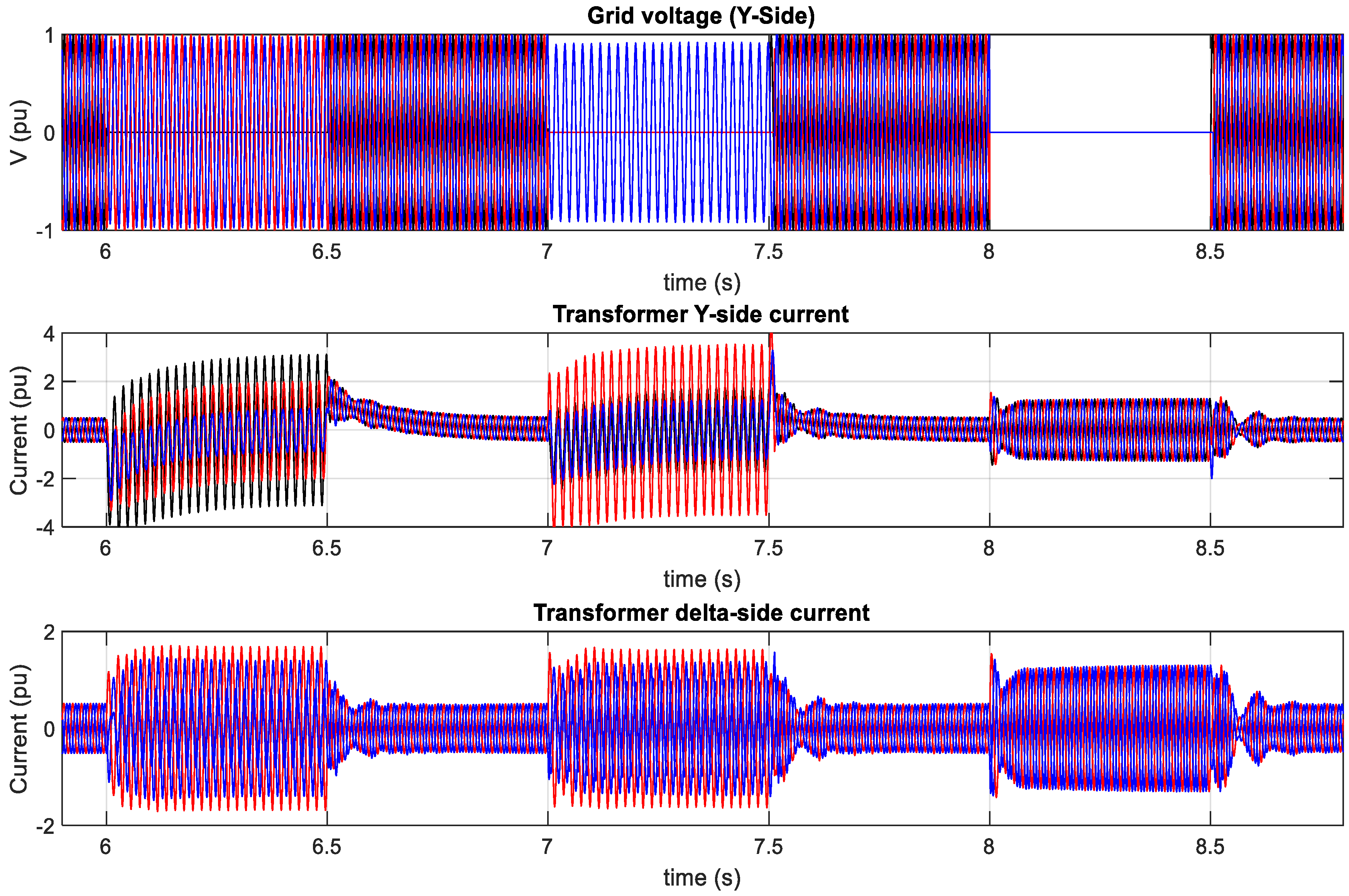
Figure 29, Figure 30, Figure 31 and Figure 32 present the Y-Δ side currents waveform and PCC1 terminal voltage waveform in RTDS and MATLAB Simulink. Since zero sequence currents flow into the Y-side transformer, Y-side current is more unsymmetrical than Δ side current during unbalanced SLG and DLG. However, both side current wave shapes are similar during the balanced three-phase fault. It is also observed that the maximum phase current remained around 1.36 pu in the Δ side transformer for all cases. However, the Y-Δ side currents for all phases remain exactly within its permissible limit during balanced fault. During unbalanced fault, one phase current in the Δ-side transformer slightly exceeds peak value. Y-side currents are around 2 pu for SLG fault and 2.667 pu for DLG fault. Since DLG fault produces more negative sequence voltage and significantly limits the power transfer capability, Y-side transformer encounters larger unsymmetrical current comparing to SLG fault.
4. Conclusions
This research develops an MMC based multiterminal HVDC transmission network for optimum wind energy integration. Field-oriented control for optimum tracking of wind energy has been implemented. Furthermore, Feed forward controller has been used to form isolated AC network. It used aggregate model to represent MMC in MATLAB/Simulink and detailed model in RTDS. Both simulation and experimental results are in full agreement. The results confirm the efficacy of the proposed MPP controller during wind speed change. The proposed controller performance has been evaluated during symmetrical and unsymmetrical faults at the PCC. The results demonstrate the effectiveness of the proposed control strategy to enhance the fault ride through capability of the system without violating current and DC link voltage limits.
The main outcomes of this study can be highlighted as follows:
- ▪
- SCIG based optimum wind energy integrated MMC-HVDC network was developed;
- ▪
- The dynamics of complete renewable energy farm was considered;
- ▪
- Aggregate model based MMC-HVDC network was developed in MATLAB Simulink;
- ▪
- Detailed model based MMC-HVDC network was developed in RTDS;
- ▪
- The effects of severe balanced and unbalanced faults were analyzed;
- ▪
- Control strategy was developed to fulfill the grid code requirements, converter current and HVDC link voltage limits.
Author Contributions
All authors collaborated on this work. All authors have read and agreed to the published version of the manuscript.
Funding
This research received no external funding.
Acknowledgments
The authors would like to acknowledge the support provided by King Fahd University of Petroleum & Minerals through the Research Group funded project #DF191004. The authors also acknowledge the funding support by King Abdullah City for Atomic and Renewable Energy (K.A. CARE), Energy Research & Innovation Center (ERIC) at KFUPM.
Conflicts of Interest
The authors declare no conflict of interest.
Nomenclature
| Wind Generator and SCIG Side Converter: | |
| SCIG | Squirrel cage induction generator |
| MSC | Machine side converter |
| Rs, Rr | SCIG stator and rotor resistance |
| is | SCIG stator current. |
| SCIG stator d-q axis voltage. | |
| SCIG stator d-q axis current. | |
| SCIG magnetizing current. | |
| Rotor angular speed | |
| Angular speed of SCIG stator voltage | |
| SCIG stator line to line rms voltage | |
| Grid Side Converter (GSC): | |
| R, L | Reactor resistance and inductance, |
| PCC | Point of common coupling, |
| PCC angular frequency, | |
| PCC d-q axis current, | |
| PCC d-q axis voltage, | |
| VSC terminal d-q axis voltage | |
| C | DC link capacitance, |
| VDC | DC link voltage, |
| DC link current | |
| MMC Converter: | |
| R, L | Arm reactor resistance and inductance, |
| PCC1 | Point of common coupling of AC grid 1 |
| AC grid angular frequency, | |
| AC grid 3-Ø voltage and current, | |
| AC grid d-q axis voltage, | |
| Ac grid d-q axis current, | |
| MMC terminal d-q axis voltage, | |
| VDC | HVDC link voltage, |
| HVDC link current | |
| C | Submodule capacitance, |
| DC link pole-to-pole capacitance | |
| N | number of submodules |
| Negative sequence d-q axis current, | |
| Negative sequence d-q axis voltage, | |
| SLG | Single line to ground |
| DLG | Double line to ground |
| 3LG | Three line to ground |
| DBR | Dynamic braking resistor |
References
- Alyami, H.; Mohamed, Y. Review and Development of MMC Employed in VSC-HVDC Systems. In Proceedings of the 2017 IEEE 30th Canadian Conference on Electrical and Computer Engineering (CCECE), Windsor, ON, Canada, 3 May–30 April 2017; pp. 1–6. [Google Scholar]
- Hossain, M.I.; Shafiullah, M.; Abido, M. VSC Controllers for Multiterminal HVDC Transmission System: A Comparative Study. Arab. J. Sci. Eng. 2020, 1–12. Available online: https://doi.org/10.1007/s13369-020-04500-y (accessed on 21 April 2020). [CrossRef]
- Alassi, A.; Bañales, S.; Ellabban, O.; Adam, G.; MacIver, C. HVDC Transmission: Technology Review, Market Trends and Future Outlook. Renew. Sustain. Energy Rev. 2019, 112, 530–554. [Google Scholar] [CrossRef]
- Li, Z.; Zhan, R.; Li, Y.; He, Y.; Hou, J.; Zhao, X.; Zhang, X.-P. Recent developments in HVDC transmission systems to support renewable energy integration. Glob. Energy Interconnect. 2018, 1, 595–607. [Google Scholar]
- Saad, H.; Mahseredjian, J.; Dennetière, S.; Nguefeu, S. Interactions studies of HVDC–MMC link embedded in an AC grid. Electr. Power Syst. Res. 2016, 138, 202–209. [Google Scholar] [CrossRef]
- Li, R.; Xu, L.; Holliday, D.; Page, F.; Finney, S.J.; Williams, B.W. Continuous Operation of Radial Multiterminal HVDC Systems Under DC Fault. IEEE Trans. Power Deliv. 2016, 31, 351–361. [Google Scholar] [CrossRef] [Green Version]
- Stamatiou, G.; Bongiorno, M. Power-dependent droop-based control strategy for multi-terminal HVDC transmission grids. IET Gener. Transm. Distrib. 2017, 11, 383–391. [Google Scholar] [CrossRef]
- Beerten, J.; Cole, S.; Belmans, R. Modeling of Multi-Terminal VSC HVDC Systems With Distributed DC Voltage Control. IEEE Trans. Power Syst. 2014, 29, 34–42. [Google Scholar] [CrossRef]
- Masmoudi, E.A.; Zhu, Z.Q.; Hu, J. Electrical machines and power-electronic systems for high-power wind energy generation applications: Part I—Market penetration, current technology and advanced machine systems. COMPEL Int. J. Comput. Math. Electr. Electron. Eng. 2012, 32, 7–33. [Google Scholar]
- Goudarzi, N.; Zhu, W.D. A review on the development of wind turbine generators across the world. Int. J. Dyn. Control 2013, 1, 192–202. [Google Scholar] [CrossRef] [Green Version]
- Zhang, Z.; Matveev, A.; Ovrebø, S.; Nilssen, R.; Nysveen, A. State of the Art in Generator Technology for Offshore Wind Energy Conversion Systems. In Proceedings of the 2011 IEEE International Electric Machines and Drives Conference, IEMDC 2011, Niagara Falls, ON, Canada, 15–18 May 2011; pp. 1131–1136. [Google Scholar]
- Sayigh, A.A.M.; Milborrow, D. The Age of Wind Energy: Progress and Future Directions from a Global Perspective; Springer International Publishing: Cham, Switzerland, 2020. [Google Scholar]
- Li, X.; Guo, L.; Hong, C.; Zhang, Y.; Li, Y.W.; Wang, C. Hierarchical Control of Multiterminal DC Grids for Large-Scale Renewable Energy Integration. IEEE Trans. Sustain. Energy 2018, 9, 1448–1457. [Google Scholar] [CrossRef]
- Yanchen, Y.; Shicong, M.; Yingbiao, L. Analysis and control strategy of unbalanced power in MMC-HVDC grid. J. Eng. 2017, 2017, 2211–2214. [Google Scholar] [CrossRef]
- Tada, K.; Sato, T.; Umemura, A.; Takahashi, R.; Tamura, J.; Matsumura, Y.; Yamaguchi, D.; Kudo, H.; Niiyama, M.; Taki, Y. Frequency control of power system including PV and wind farms by using output frequency band control of HVDC interconnection line. J. Eng. 2019, 2019, 4879–4883. [Google Scholar] [CrossRef]
- Lyu, J.; Cai, X.; Molinas, M. Optimal Design of Controller Parameters for Improving the Stability of MMC-HVDC for Wind Farm Integration. IEEE J. Emerg. Sel. Top. Power Electron. 2018, 6, 40–53. [Google Scholar] [CrossRef] [Green Version]
- Liang, J.; Jing, T.; Gomis-Bellmunt, O.; Ekanayake, J.; Jenkins, N. Operation and Control of Multiterminal HVDC Transmission for Offshore Wind Farms. IEEE Trans. Power Deliv. 2011, 26, 2596–2604. [Google Scholar] [CrossRef]
- Liang, J.; Gomis-Bellmunt, O.; Ekanayake, J.; Jenkins, N.; An, W. A multi-terminal HVDC transmission system for offshore wind farms with induction generators. Int. J. Electr. Power Energy Syst. 2012, 43, 54–62. [Google Scholar] [CrossRef]
- Raza, M.; Peñalba, M.A.; Gomis-Bellmunt, O. Short circuit analysis of an offshore AC network having multiple grid forming VSC-HVDC links. Int. J. Electr. Power Energy Syst. 2018, 102, 364–380. [Google Scholar] [CrossRef]
- Cui, S.; Lee, H.-J.; Jung, J.-J.; Lee, Y.; Sul, S.-K. A Comprehensive AC-Side Single-Line-to-Ground Fault Ride Through Strategy of an MMC-Based HVDC System. IEEE J. Emerg. Sel. Top. Power Electron. 2018, 6, 1021–1031. [Google Scholar] [CrossRef]
- Olowookere, O.; Skarvelis-Kazakos, S.; Habtay, Y.; Woodhead, S. AC Fault Ride through of Modular Multilevel Converter VSC-HVDC Transmission Systems. In Proceedings of the 2015 50th International Universities Power Engineering Conference (UPEC), Stroke-on-Trent, UK, 1–4 September 2015; pp. 1–6. [Google Scholar]
- Feltes, C.; Wrede, H.; Koch, F.W.; Erlich, I. Enhanced Fault Ride-Through Method for Wind Farms Connected to the Grid Through VSC-Based HVDC Transmission. IEEE Trans. Power Syst. 2009, 24, 1537–1546. [Google Scholar] [CrossRef]
- Xu, L.; Andersen, B.R. Grid connection of large offshore wind farms using HVDC. Wind Energy 2006, 9, 371–382. [Google Scholar] [CrossRef]
- Nanou, S.; Papathanassiou, S. Evaluation of a communication-based fault ride-through scheme for offshore wind farms connected through high-voltage DC links based on voltage source converter. IET Renew. Power Gener. 2015, 9, 882–891. [Google Scholar] [CrossRef]
- Cui, S.; Lee, H.-J.; Jung, J.-J.; Lee, Y.; Sul, S.-K. A Comprehensive AC Side Single Line to Ground Fault Ride through Strategy of a Modular Multilevel Converter for HVDC System. In Proceedings of the 2015 IEEE Energy Conversion Congress and Exposition (ECCE), Montreal, QC, Canada, 20–24 September 2015; pp. 5378–5385. [Google Scholar]
- Oguma, K.; Akagi, H. Low-Voltage-Ride-Through (LVRT) Control of an HVDC Transmission System Using Two Modular Multilevel DSCC Converters. IEEE Trans. Power Electron. 2017, 32, 5931–5942. [Google Scholar] [CrossRef]
- Beza, M.; Bongiorno, M. Identification of resonance interactions in offshore-wind farms connected to the main grid by MMC-based HVDC system. Int. J. Electr. Power Energy Syst. 2019, 111, 101–113. [Google Scholar] [CrossRef]
- Jing, Y.; Li, R.; Xu, L.; Wang, Y. Enhanced AC voltage and frequency control on offshore MMC station for wind farm. J. Eng. 2017, 2017, 1264–1268. [Google Scholar] [CrossRef]
- Yu, L.; Li, R.; Xu, L. Distributed PLL-Based Control of Offshore Wind Turbines Connected with Diode-Rectifier-Based HVDC Systems. IEEE Trans. Power Deliv. 2018, 33, 1328–1336. [Google Scholar] [CrossRef] [Green Version]
- Yazdani, A.; Iravani, R. Voltage-Sourced Converters in Power Systems: Modeling, Control, and Applications; IEEE Press/John Wiley: Hoboken, NJ, USA, 2010. [Google Scholar]
- Slootweg, J.G.; Polinder, H.; Kling, W.L. Representing Wind Turbine Electrical Generating Systems in Fundamental Frequency Simulations. IEEE Trans. Energy Convers. 2003, 18, 516–524. [Google Scholar] [CrossRef] [Green Version]
- He, L.; Zhang, K.; Xiong, J.; Fan, S. A Repetitive Control Scheme for Harmonic Suppression of Circulating Current in Modular Multilevel Converters. IEEE Trans. Power Electron. 2015, 30, 471–481. [Google Scholar] [CrossRef]
- Agelidis, V.G.; Pou, J.; Ceballos, S.; Darus, R.; Konstantinou, G. Controllers for eliminating the ac components in the circulating current of modular multilevel converters. IET Power Electron. 2016, 9, 1–8. [Google Scholar]
Figure 1.
Wind energy integrated multiterminal HVDC network.
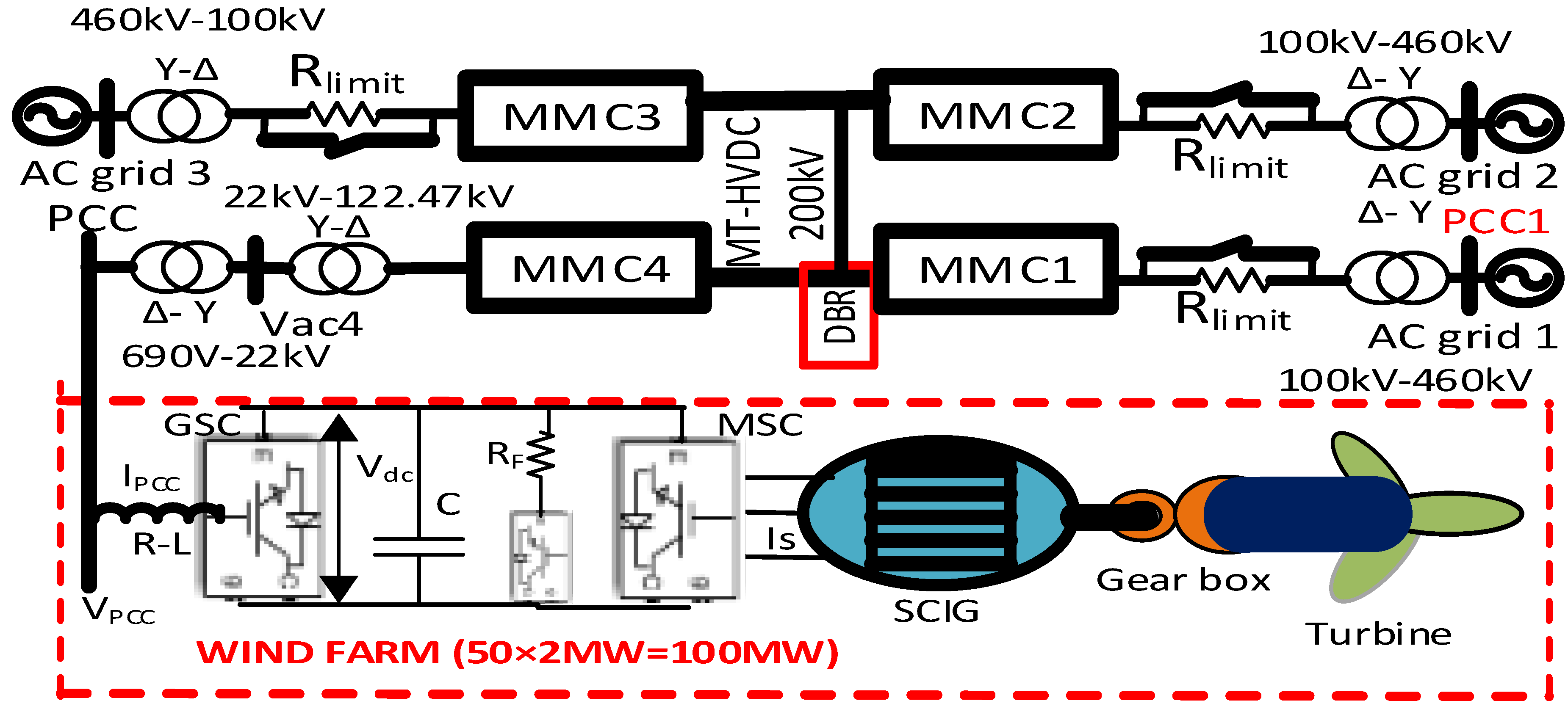
Figure 2.
Wind turbine characteristics.
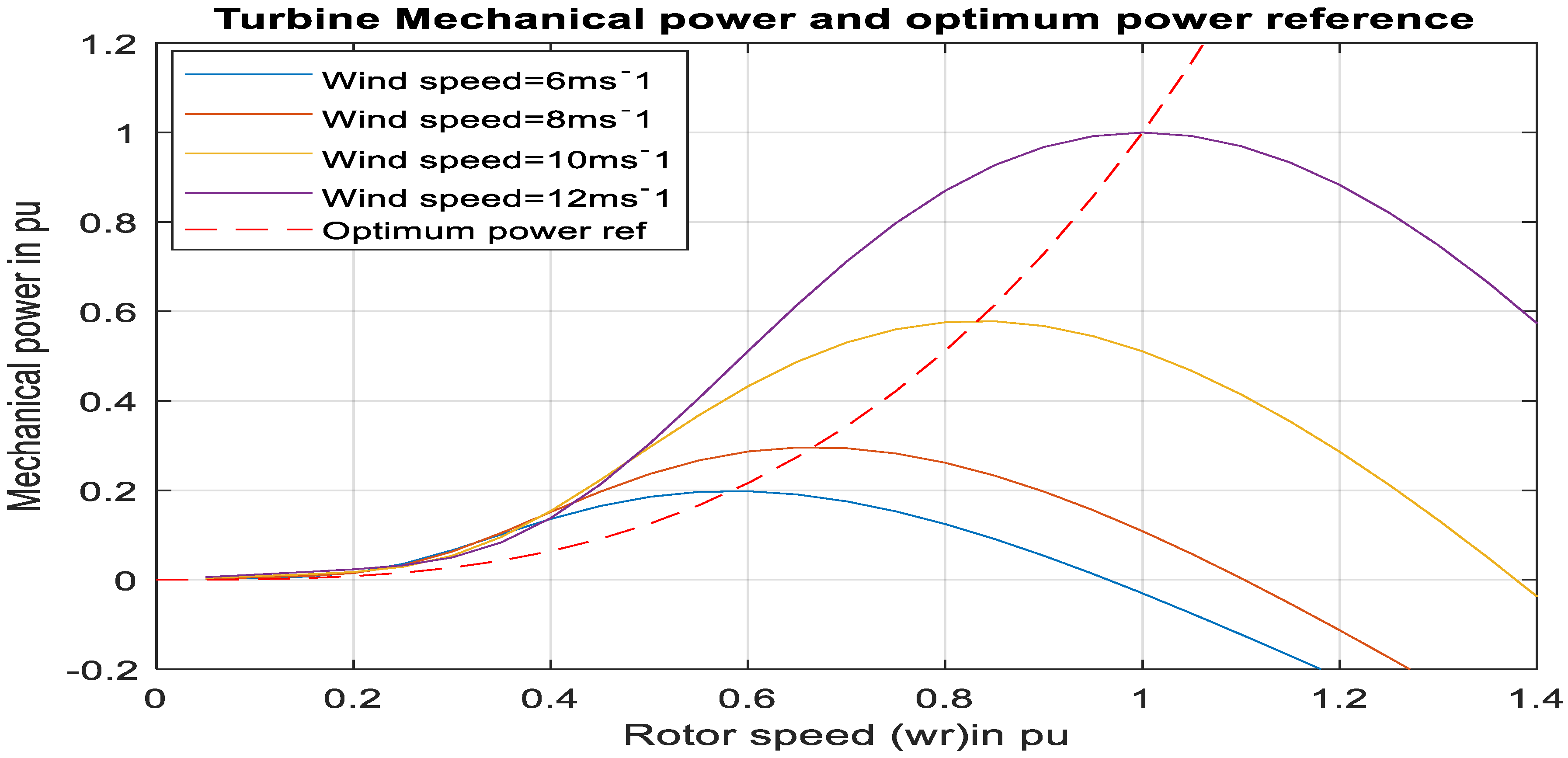
Figure 3.
Wind generator side converter control.

Figure 4.
Grid side converter control.
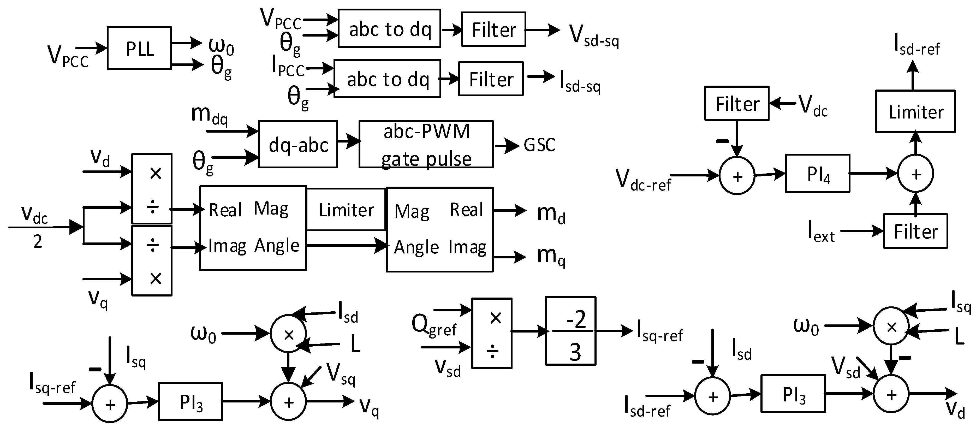
Figure 5.
Optimum wind power flow to machine side DC link for wind speed variation.
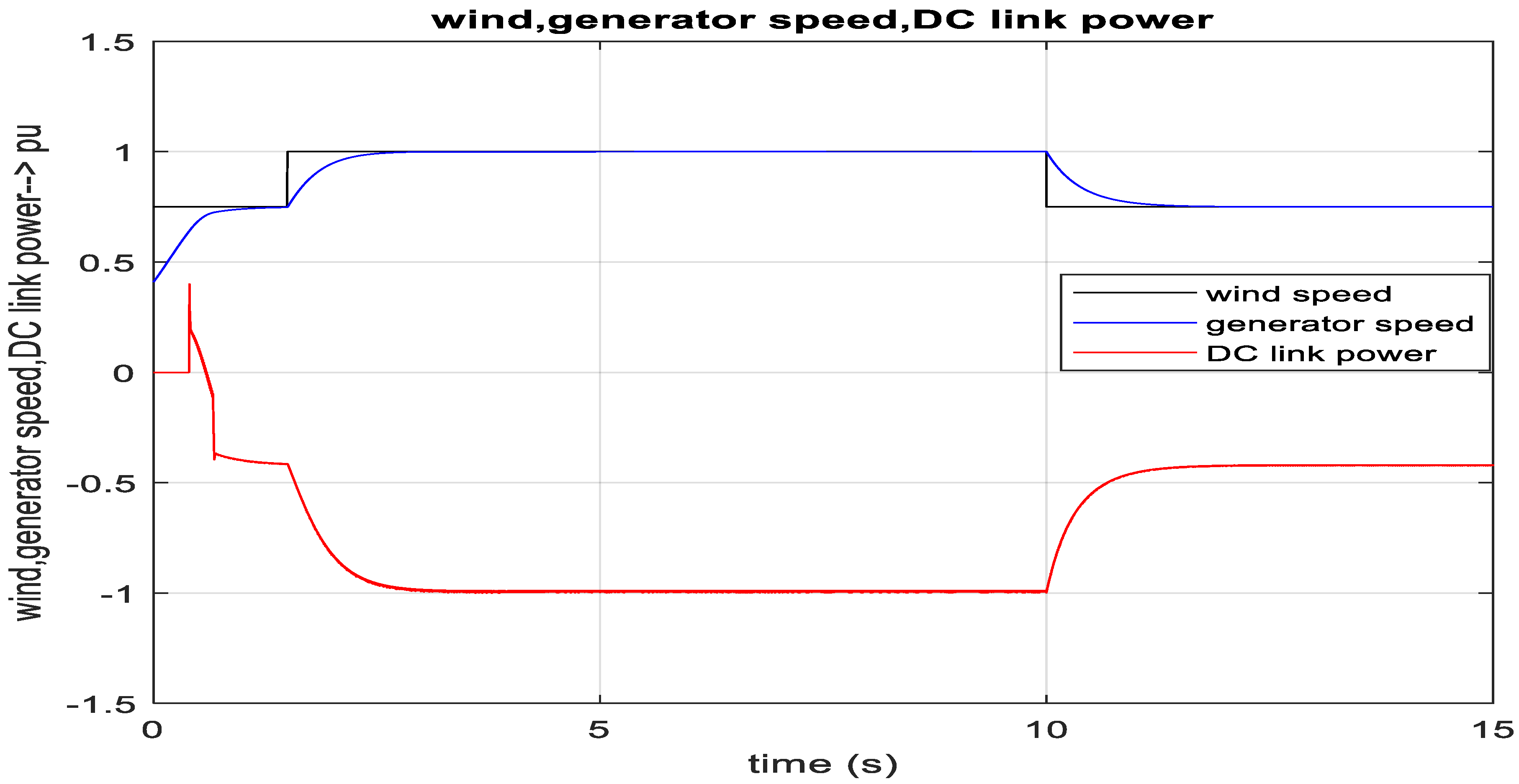
Figure 6.
Optimum electrical torque reference, actual electrical and mechanical torque.
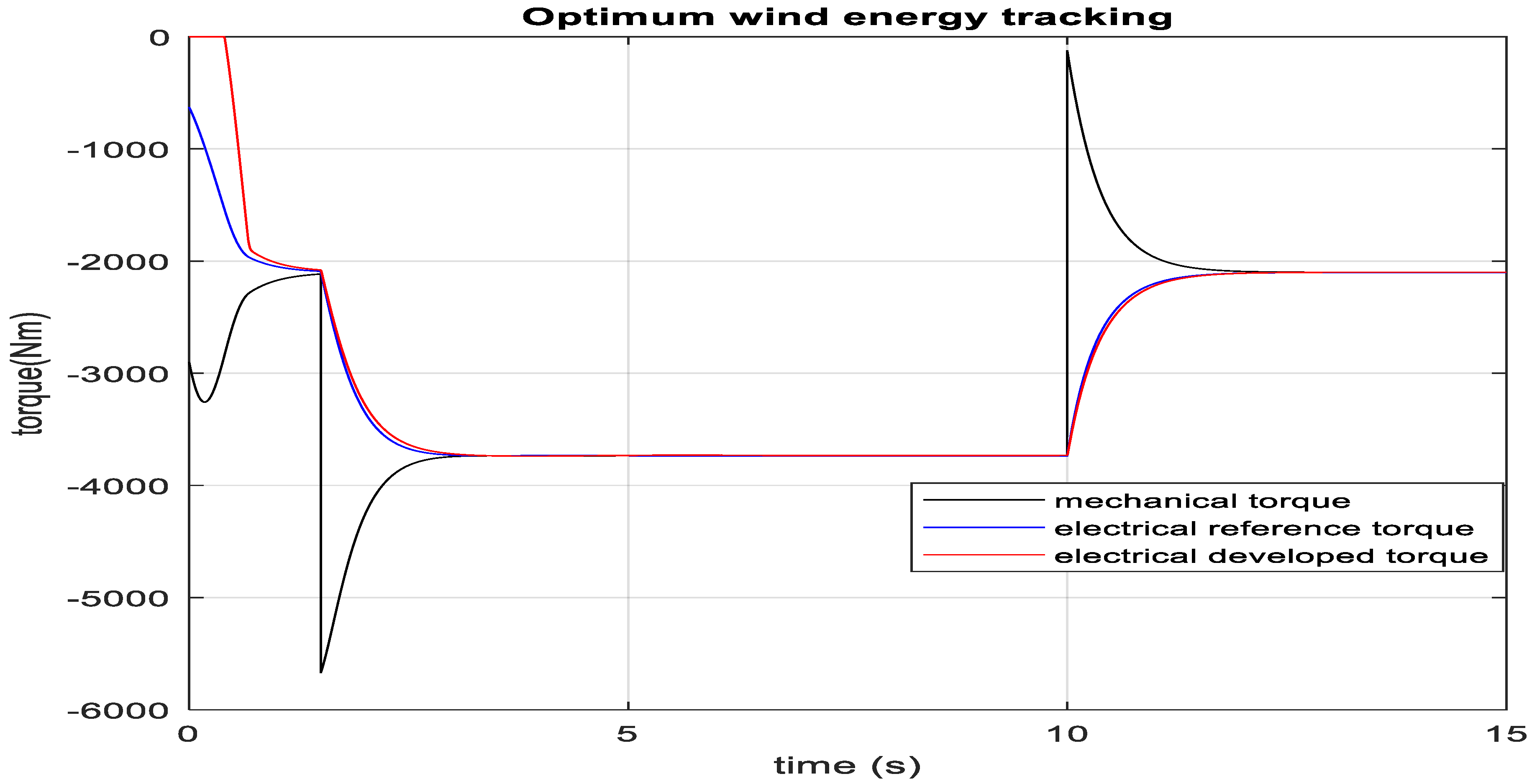
Figure 7.
Performance of current controller of machine side VSC.
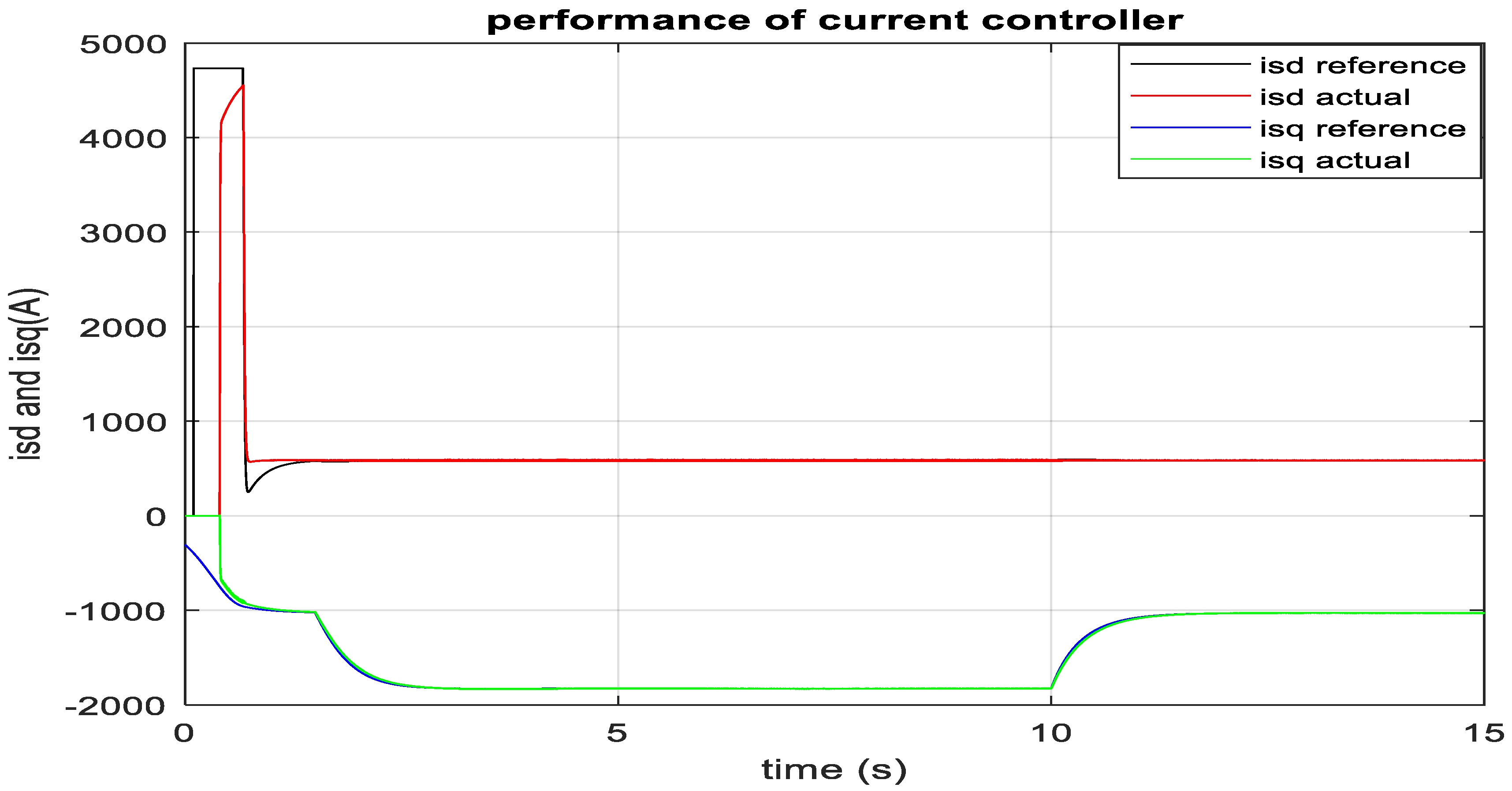
Figure 8.
MMC equivalent circuit and high level control of MMC converter.
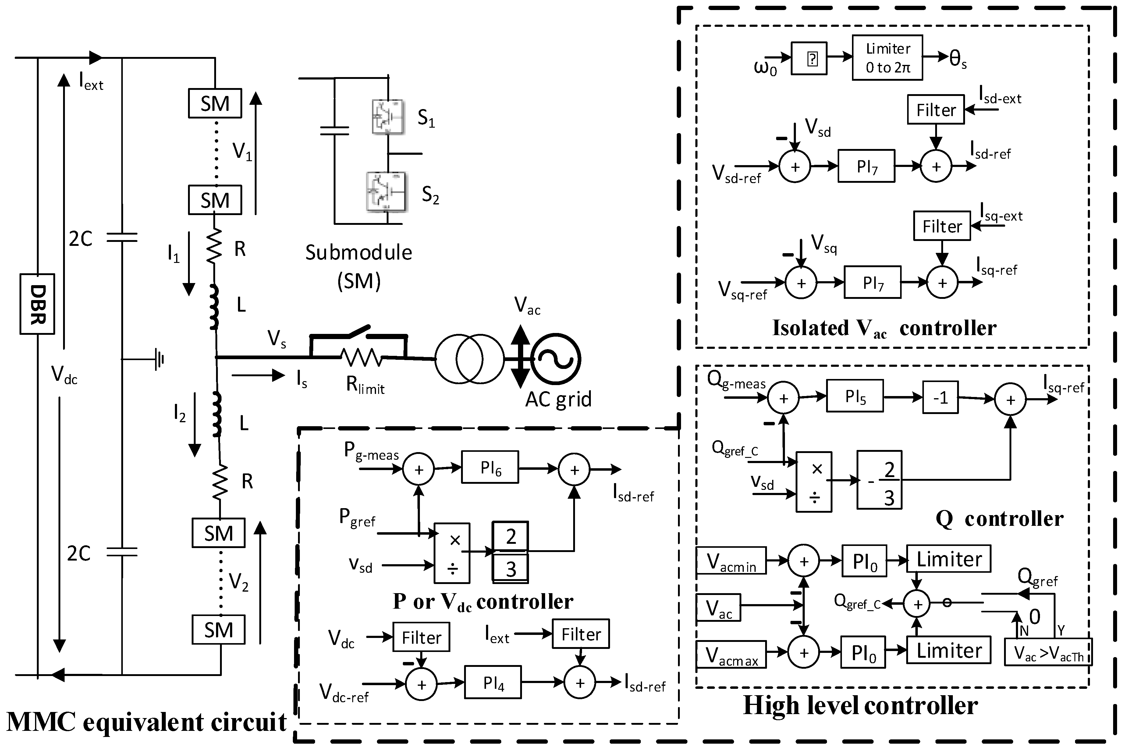
Figure 9.
Low-level control of MMC converter.
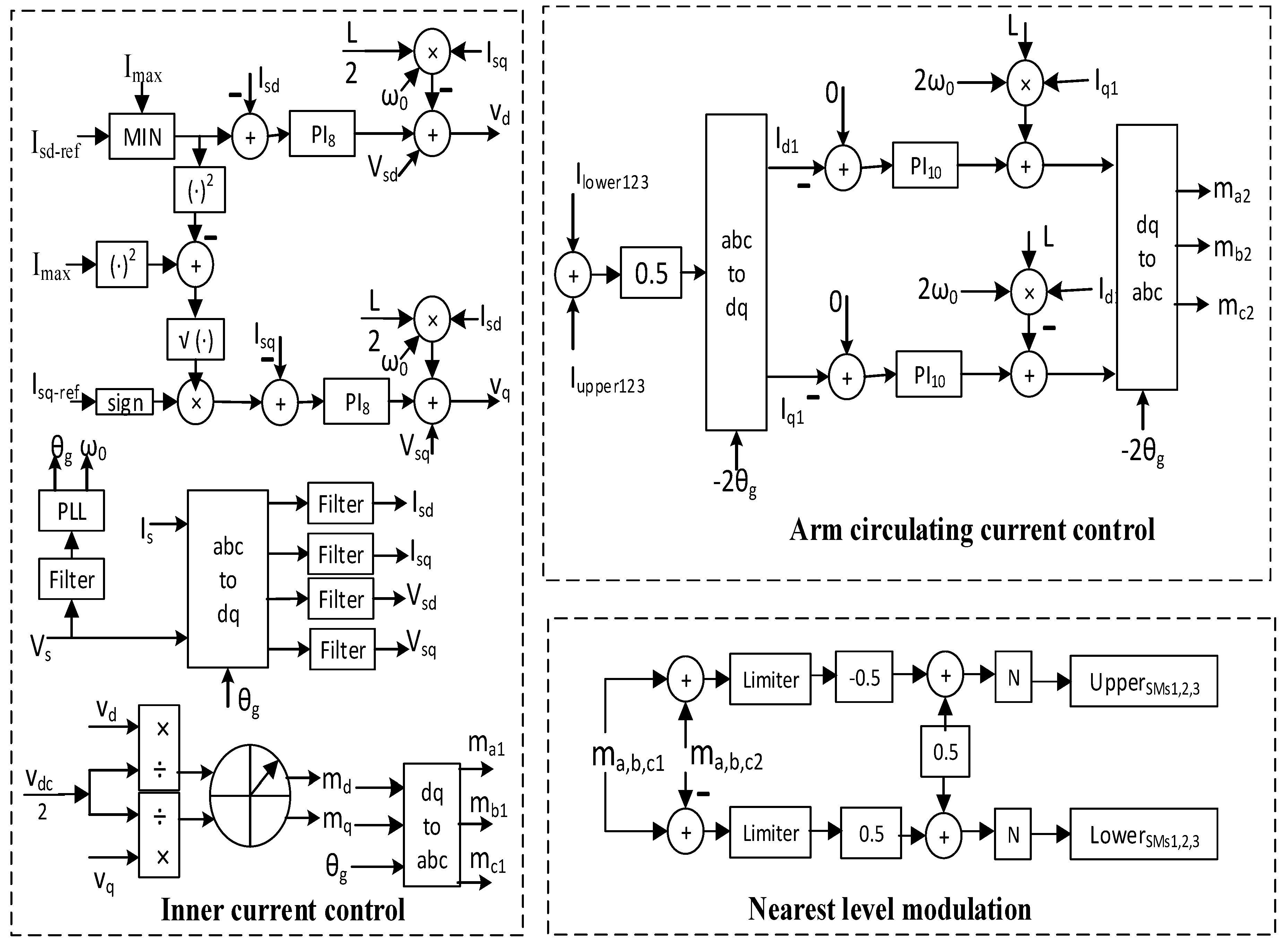
Figure 10.
Aggregate model of upper/lower arm of MMC Bridge.
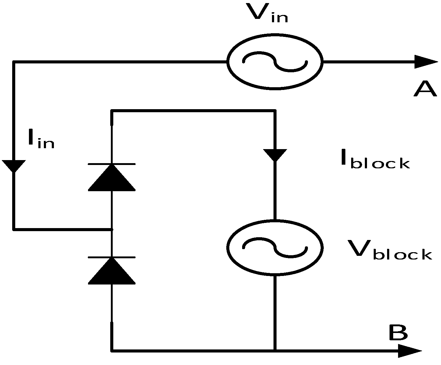
Figure 11.
RTDS run time interface of the complete system with running data.
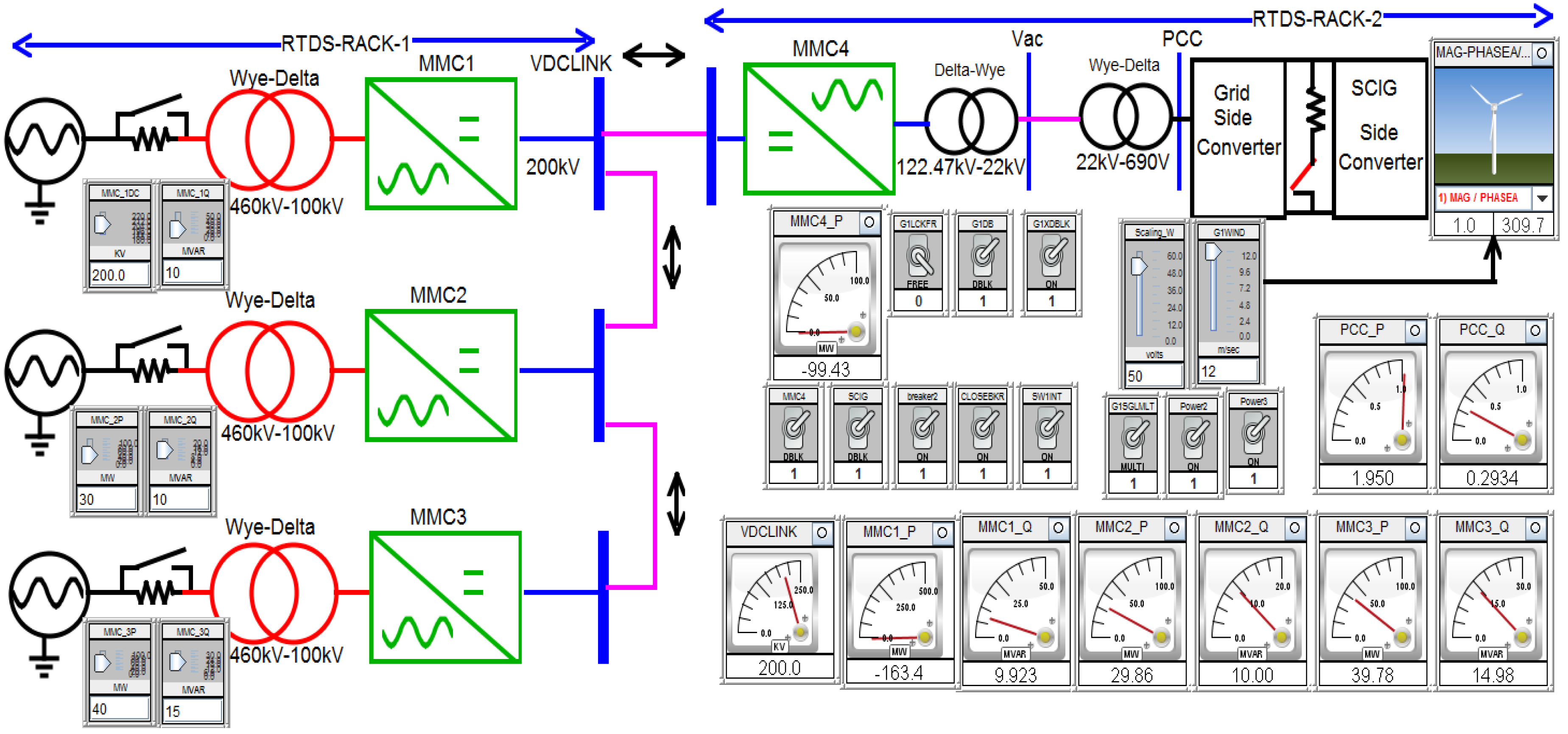
Figure 12.
MMC1 HVDC link voltage and MMC4 AC side voltage controller.

Figure 13.
MMC1-HVDC link voltage control in RTDS.
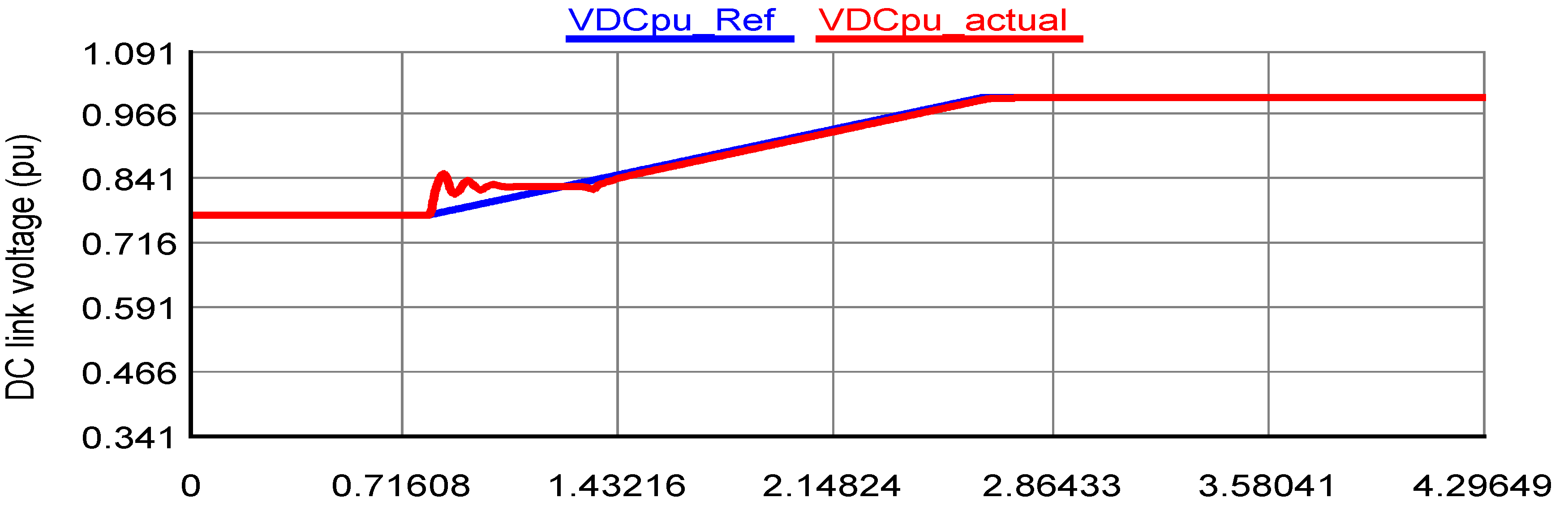
Figure 14.
MMC4 AC link voltage control in RTDS.

Figure 15.
Optimum wind energy integration into MMC4 terminal.
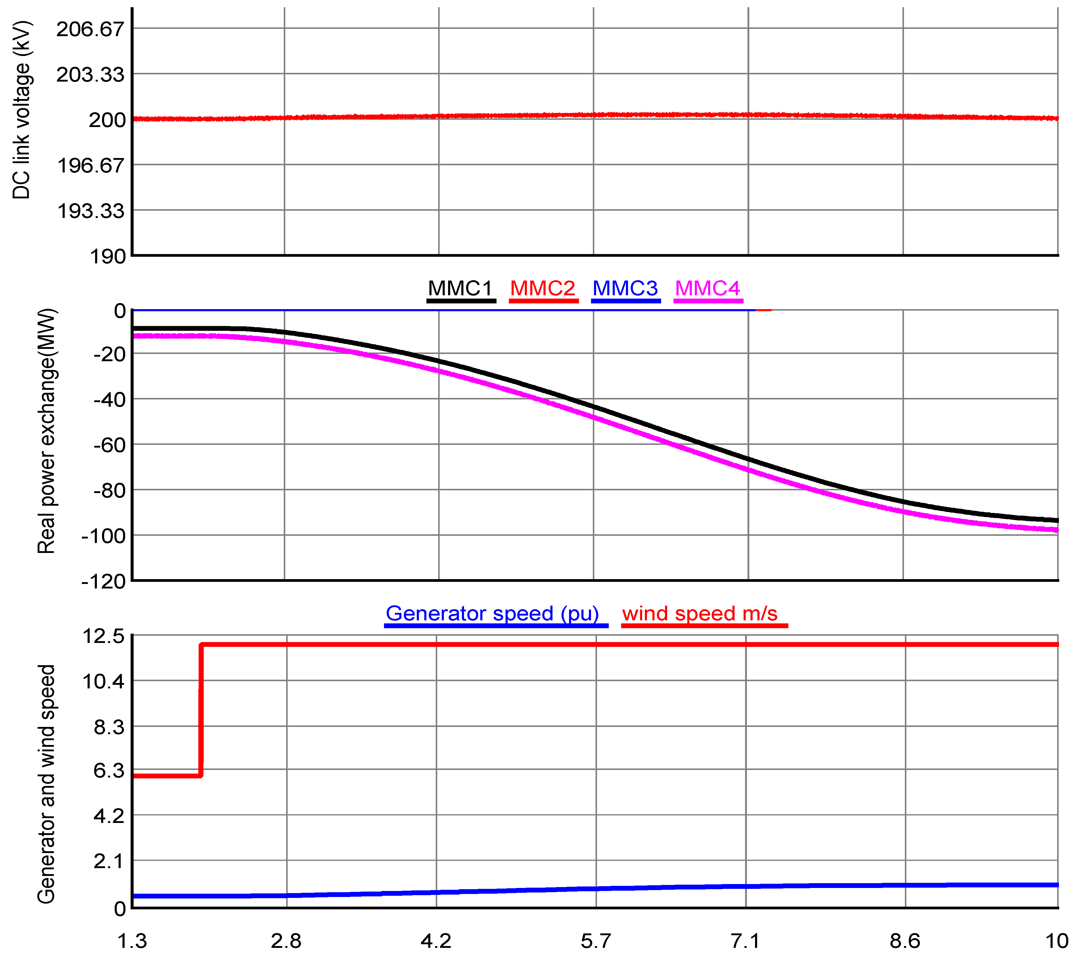
Figure 16.
Performance of current (A) controller of machine side VSC in RTDS.
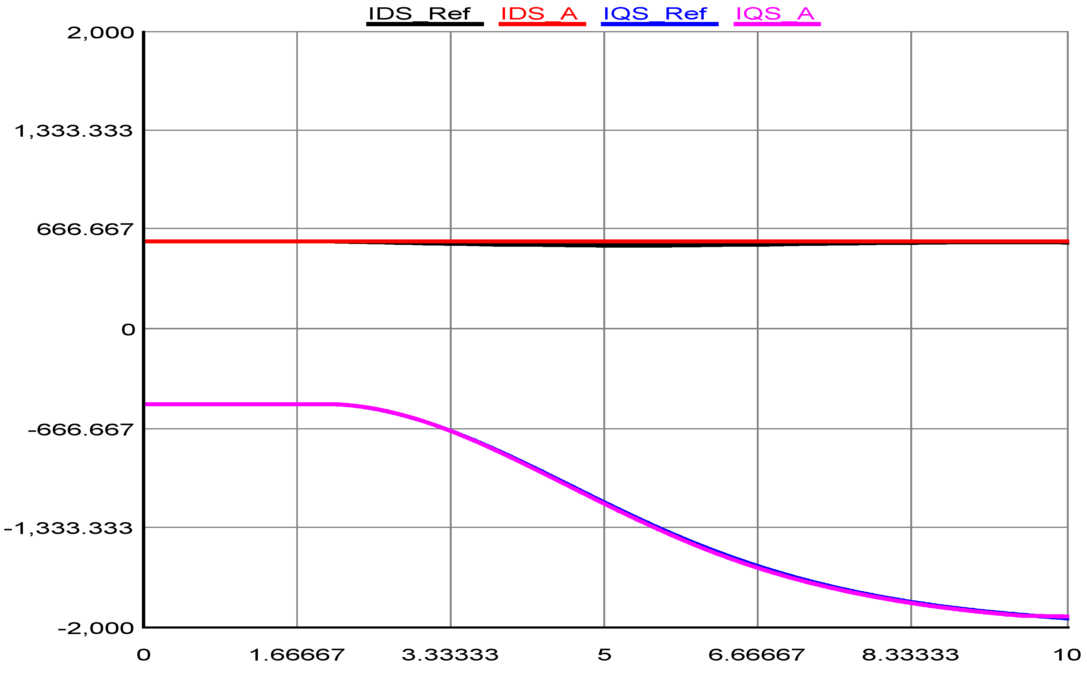
Figure 17.
Energy exchange in MMC based multiterminal HVDC transmission network in MATLAB Simulink.
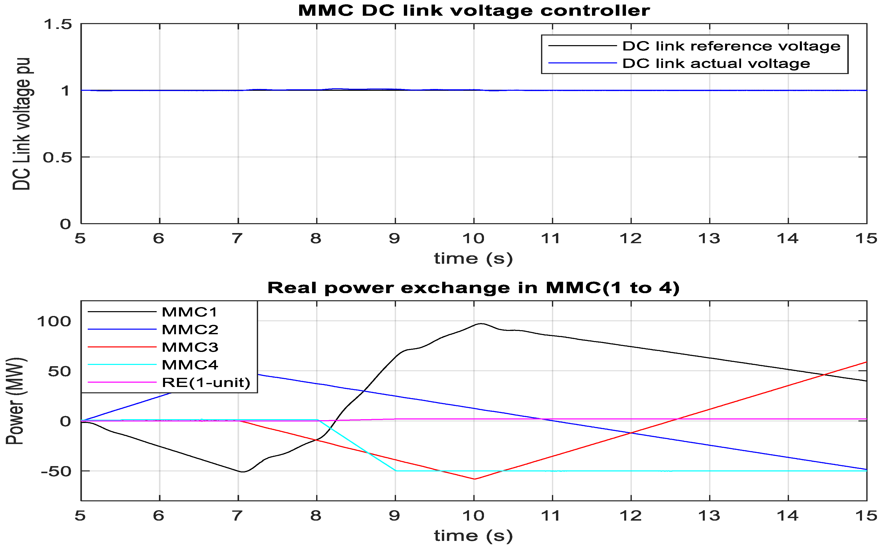
Figure 18.
Power exchange in multiterminal HVDC network in RTDS.
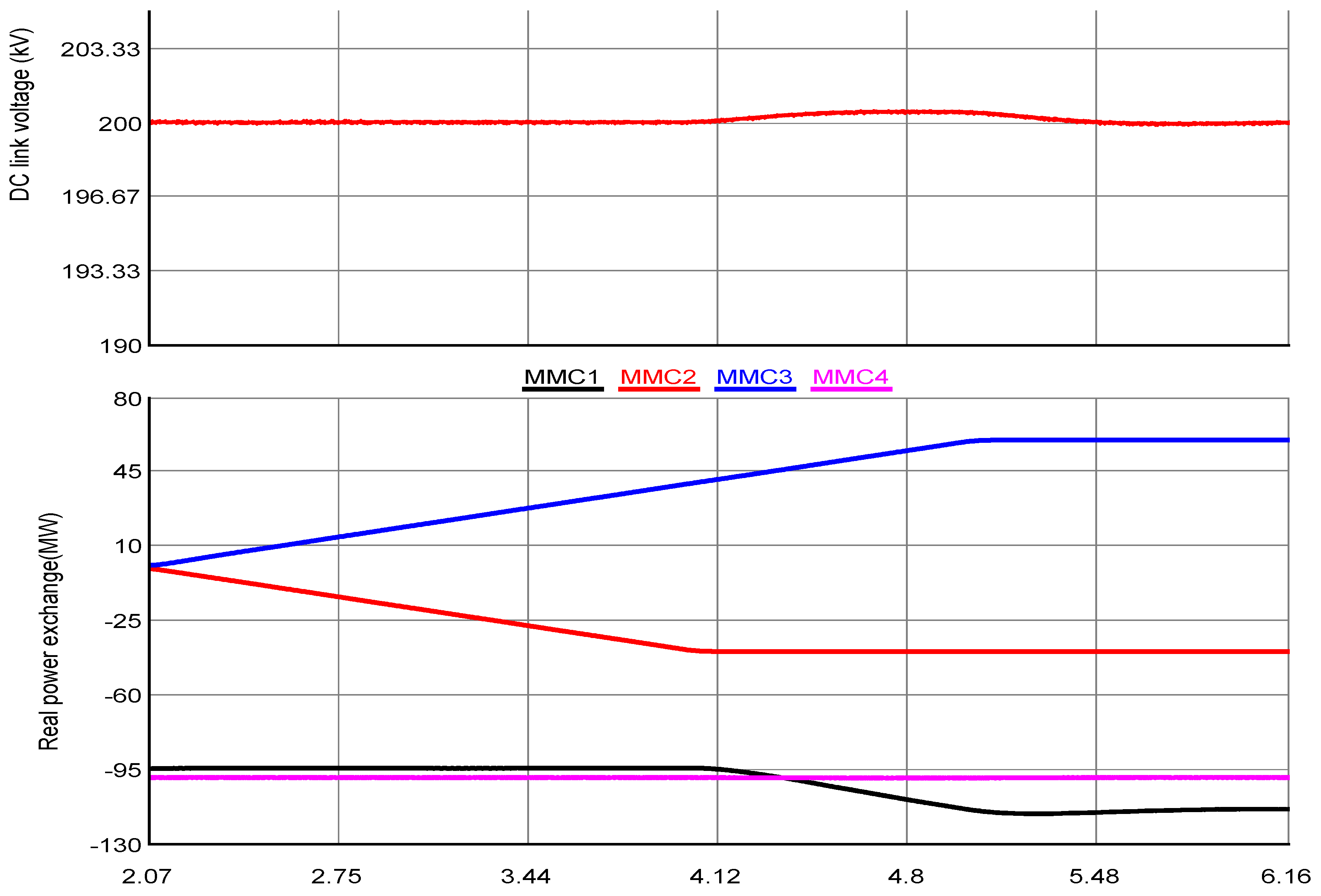
Figure 19.
Performance of HVDC link voltage controller of MMC1 during over/under frequency of PCC1 voltage in MATLAB Simulink.
Figure 19.
Performance of HVDC link voltage controller of MMC1 during over/under frequency of PCC1 voltage in MATLAB Simulink.
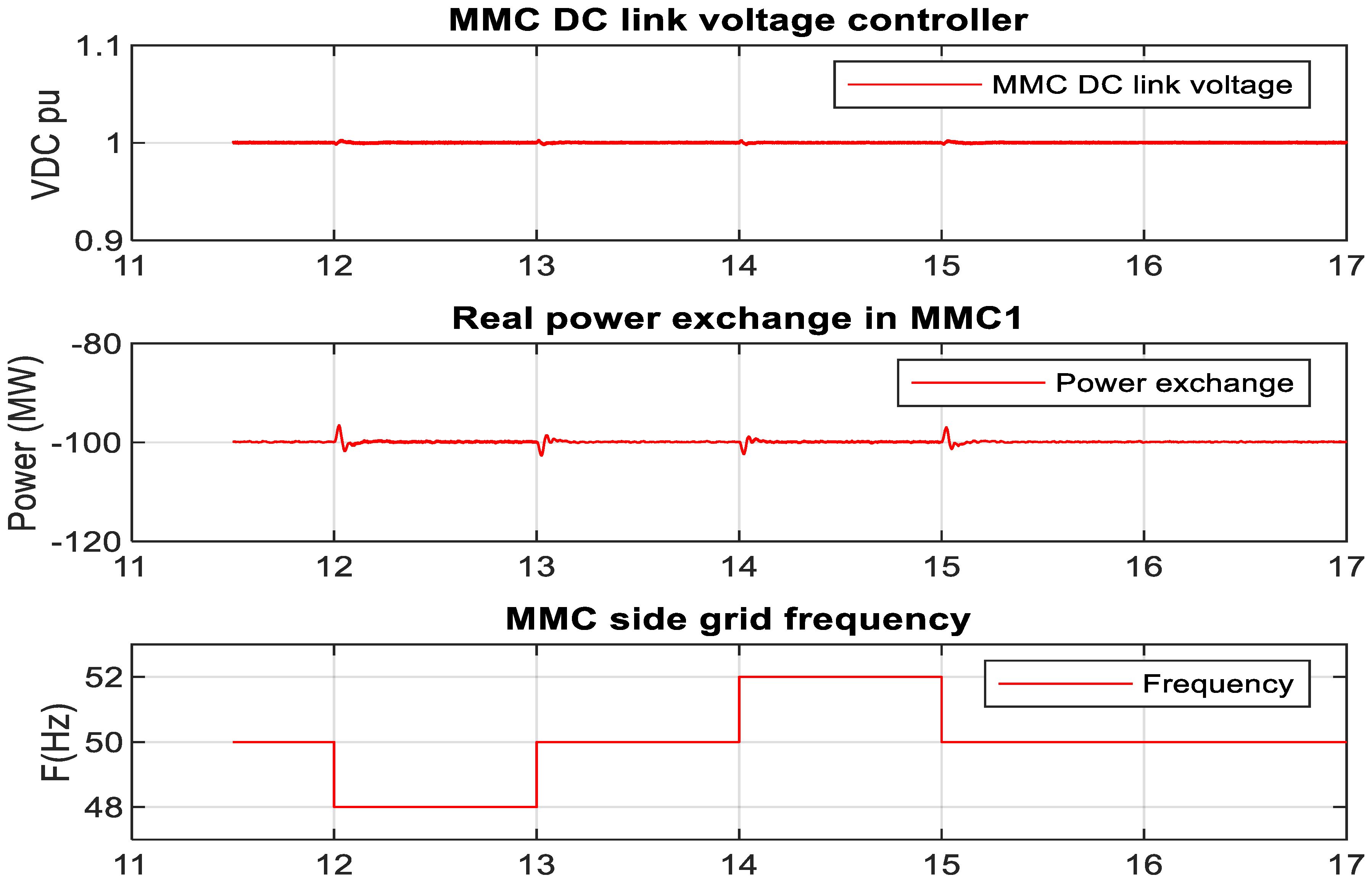
Figure 20.
Performance of DC link voltage controller of MMC1 during over/under frequency of PCC1 voltage in RTDS.
Figure 20.
Performance of DC link voltage controller of MMC1 during over/under frequency of PCC1 voltage in RTDS.
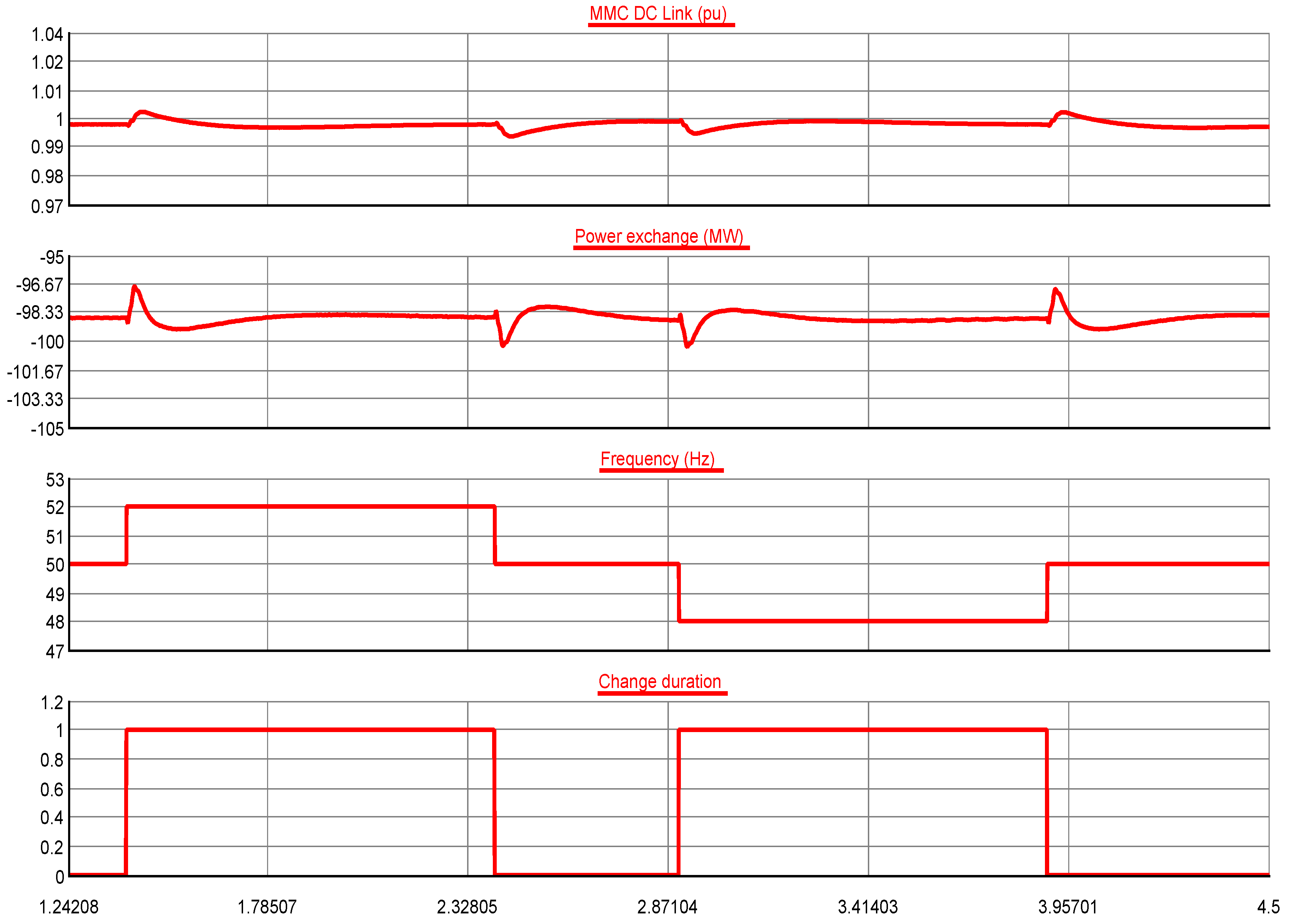
Figure 21.
Power exchange and DC link voltage of MMC1 during SLG fault at PCC1 in RTDS.
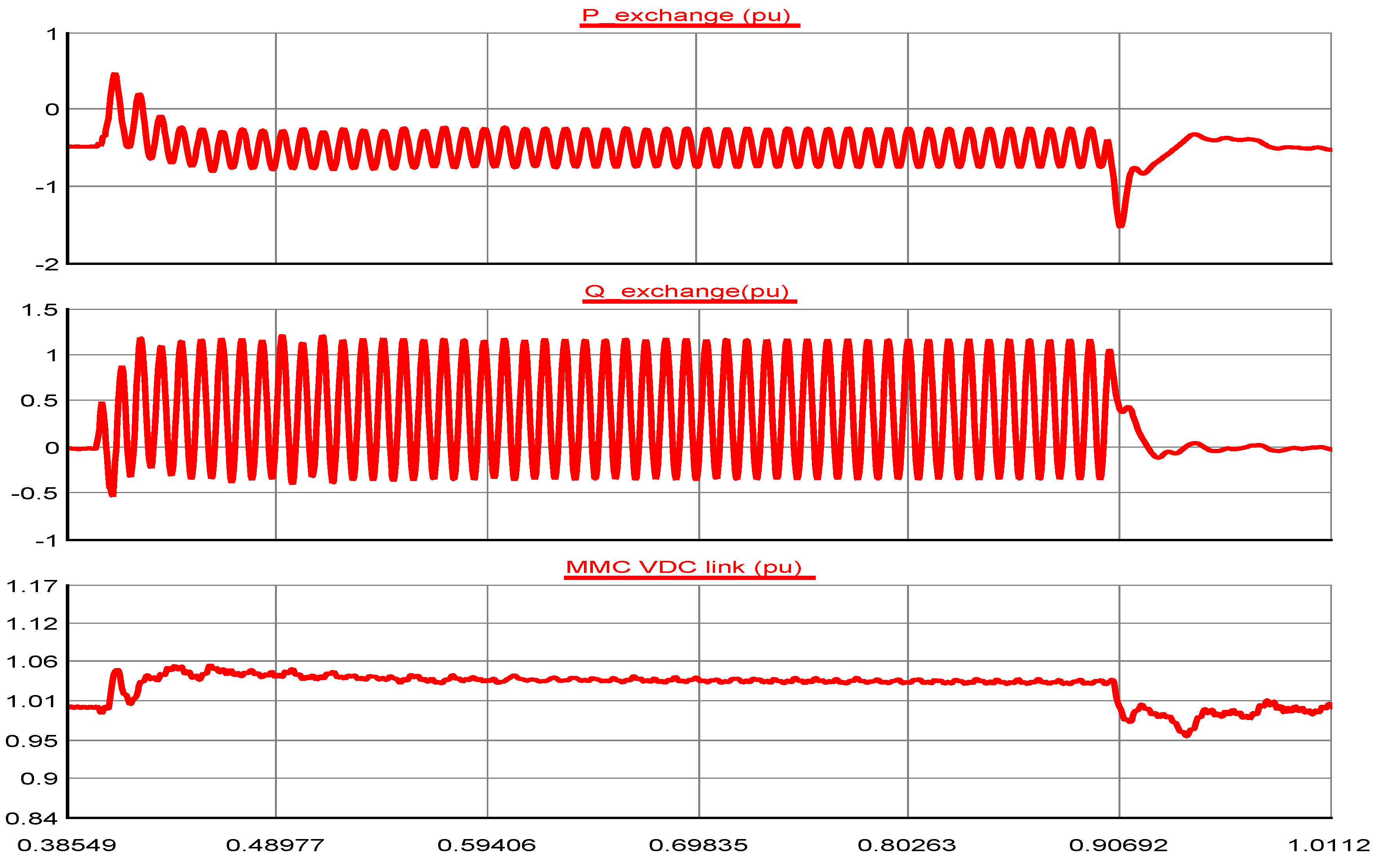
Figure 22.
Power exchange and DC link voltage of MMC1 during DLG fault at PCC1 in RTDS.

Figure 23.
Power exchange and DC link voltage of MMC1 during 3LG fault at PCC1 in RTDS.
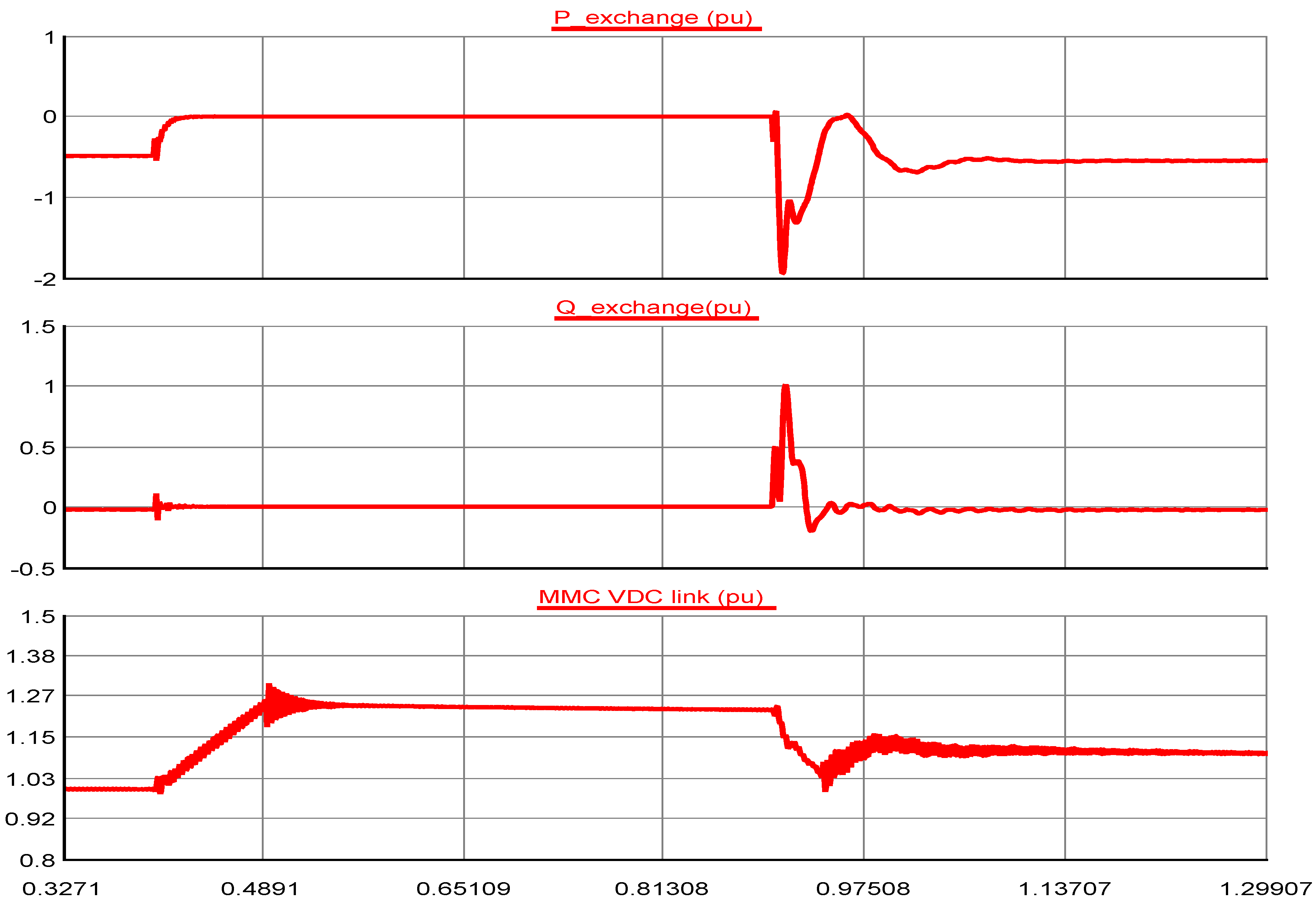
Figure 24.
Power exchange and DC link voltage of MMC1 during SLG, DLG and 3LG fault at PCC1 in MATLAB Simulink.
Figure 24.
Power exchange and DC link voltage of MMC1 during SLG, DLG and 3LG fault at PCC1 in MATLAB Simulink.
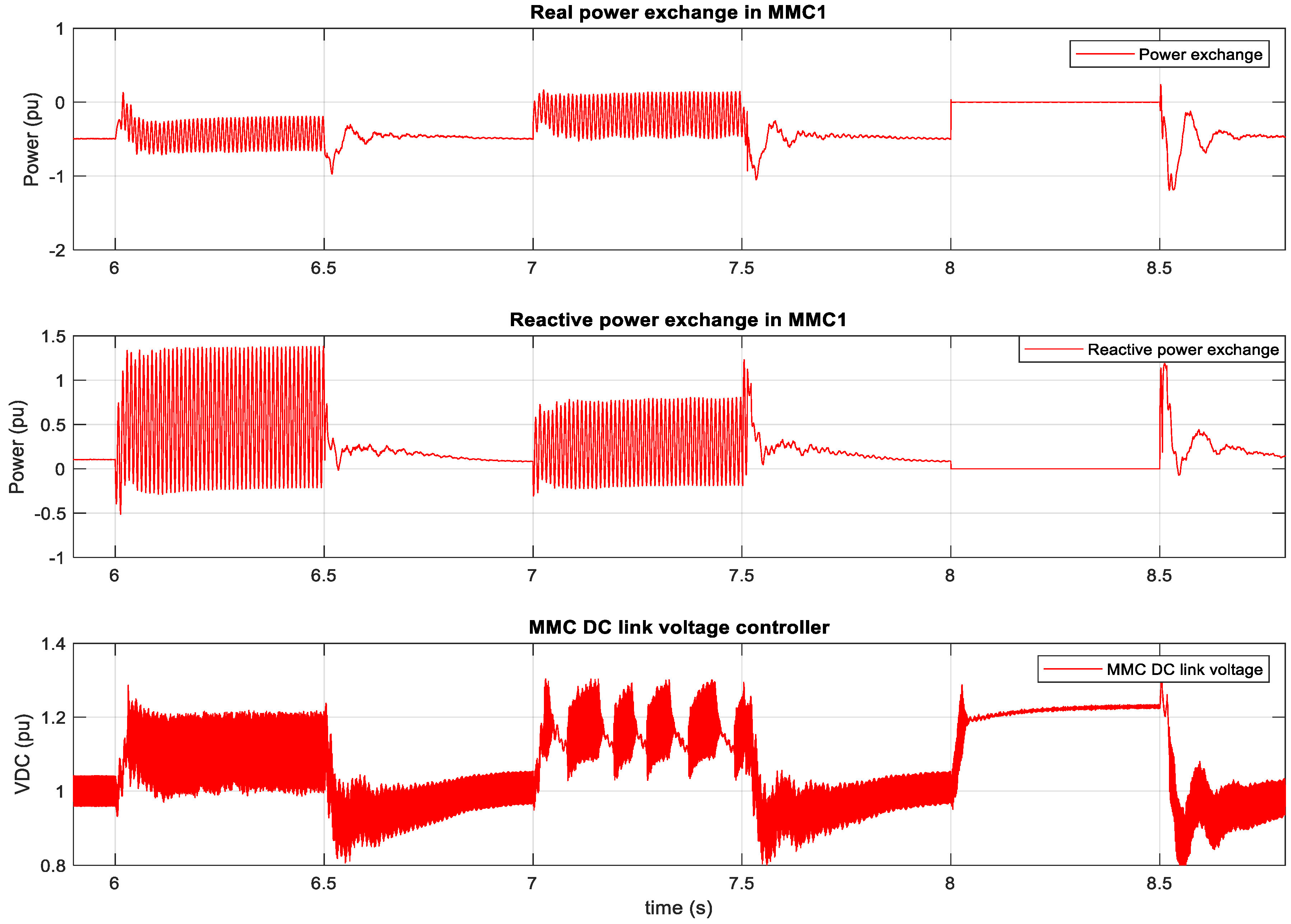
Figure 25.
Id and Iq current (pu) of MMC1 during SLG at PCC1 in RTDS.

Figure 26.
Id and Iq current (pu) of MMC1 during DLG at PCC1 in RTDS.
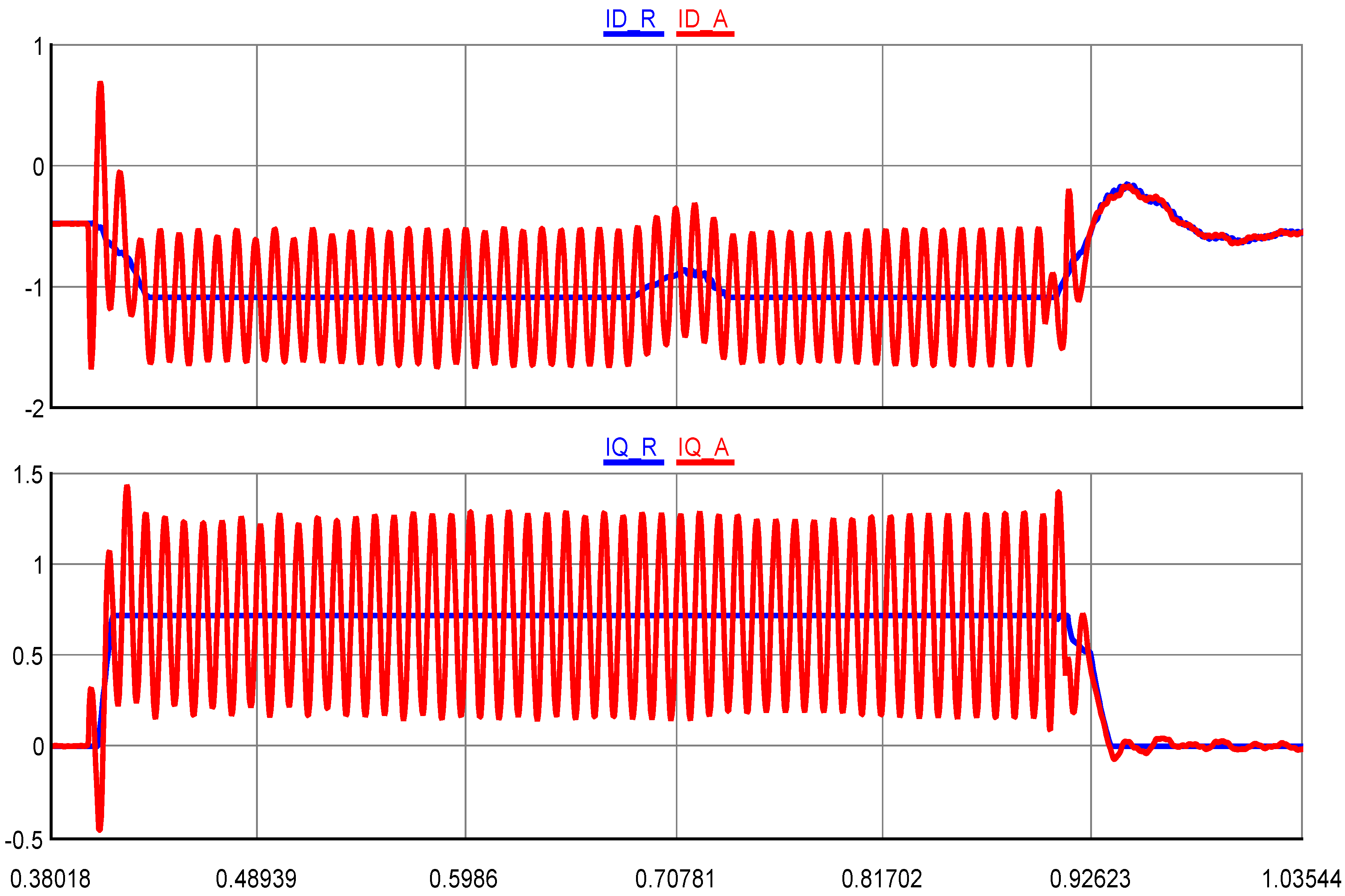
Figure 27.
Id and Iq current (pu) of MMC1 during 3LG at PCC1 in RTDS.
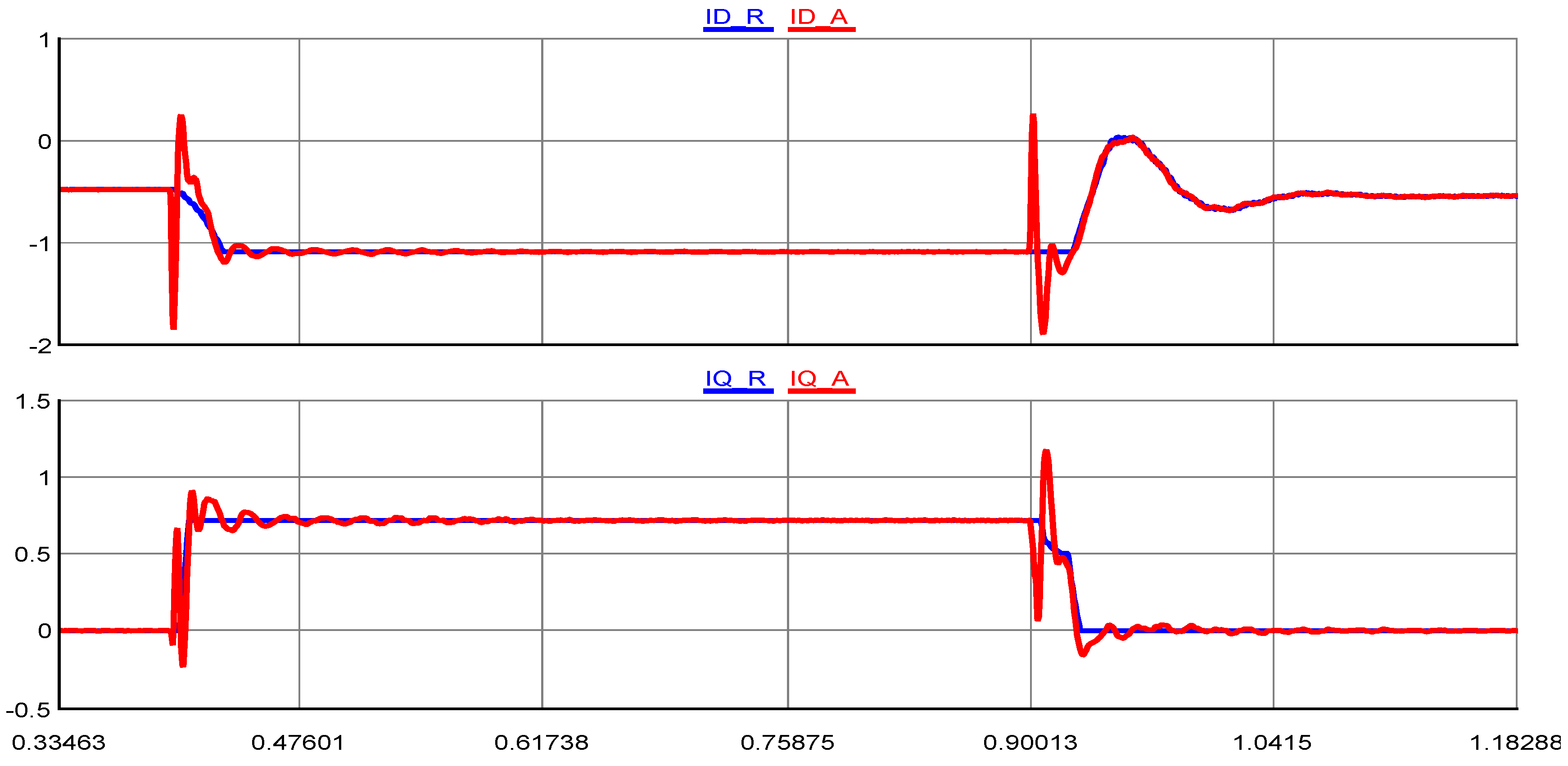
Figure 28.
Id and Iq current (pu) of MMC1 during SLG, DLG and 3LG fault at PCC1 in MATLAB Simulink.
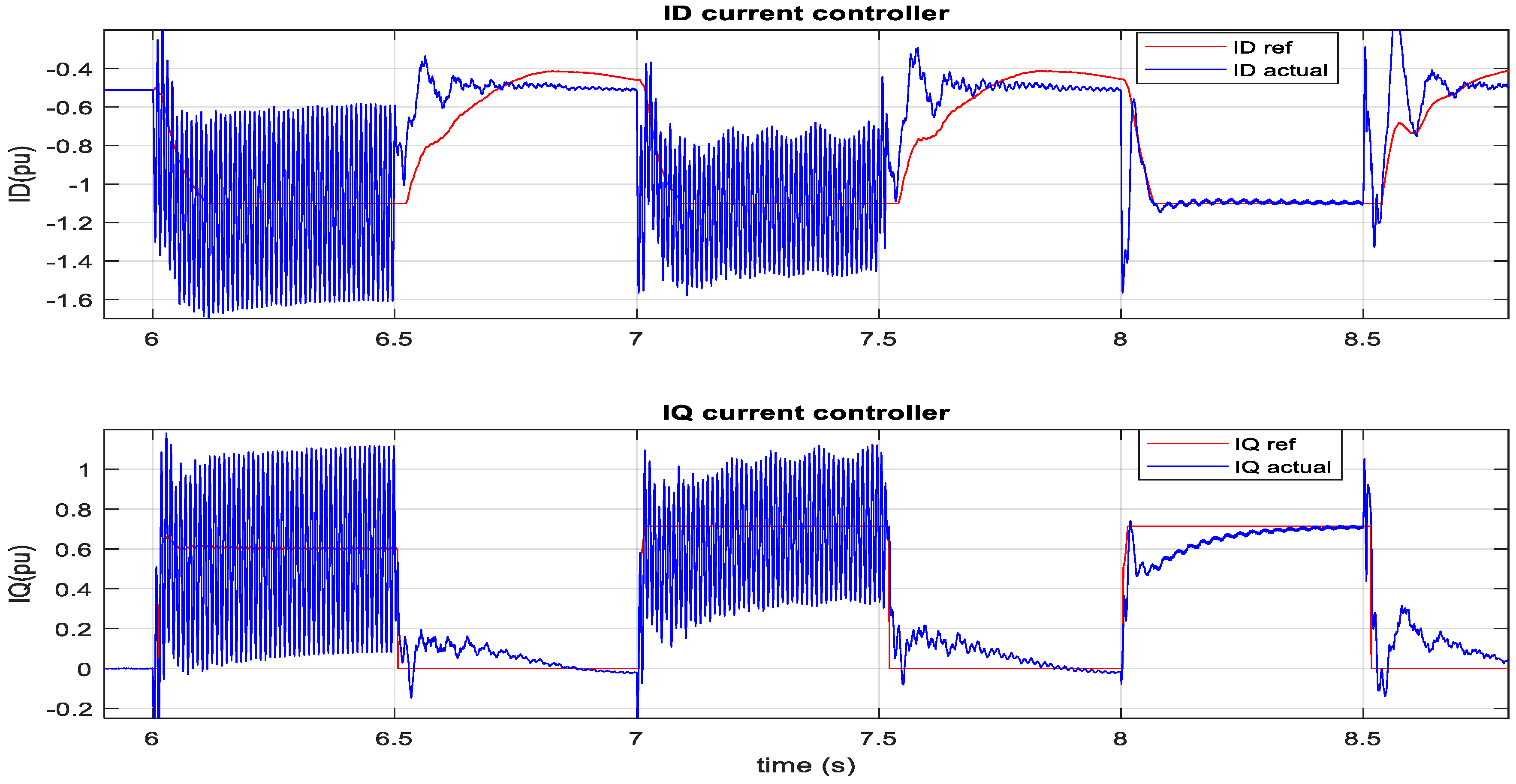
Figure 29.
Grid side voltage (PCC1), Y-side and Δ-side current (pu) of transformer connected MMC1 during SLG fault in RTDS.
Figure 29.
Grid side voltage (PCC1), Y-side and Δ-side current (pu) of transformer connected MMC1 during SLG fault in RTDS.

Figure 30.
Grid side voltage (PCC1), Y-side and Δ-side current (pu) of the transformer connected MMC1 during DLG fault in RTDS.
Figure 30.
Grid side voltage (PCC1), Y-side and Δ-side current (pu) of the transformer connected MMC1 during DLG fault in RTDS.

Figure 31.
Grid side voltage (PCC1), Y-side and Δ-side current (pu) of the transformer connected MMC1 during 3LG fault in RTDS.
Figure 31.
Grid side voltage (PCC1), Y-side and Δ-side current (pu) of the transformer connected MMC1 during 3LG fault in RTDS.
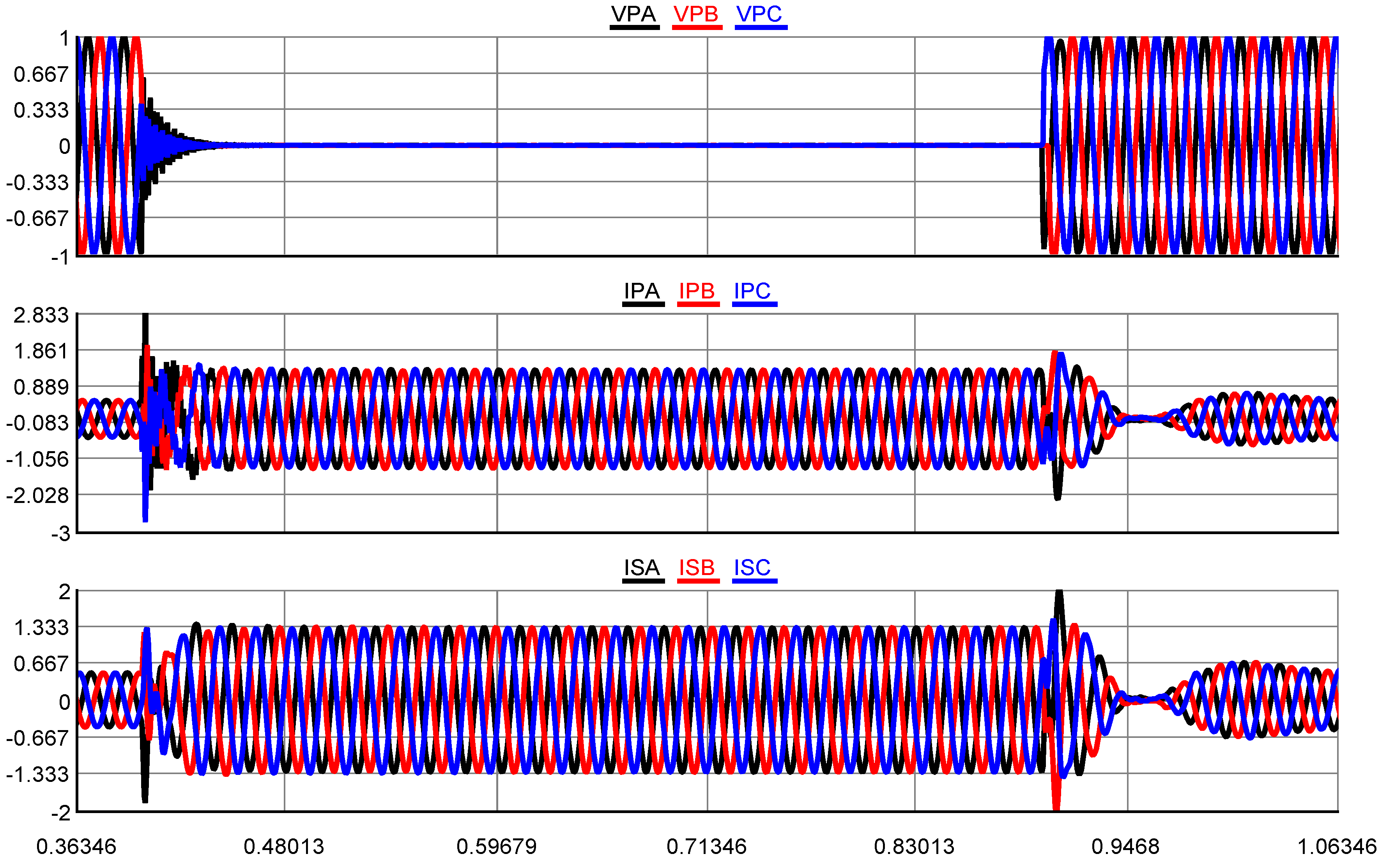
Figure 32.
Grid side voltage (PCC1), Y-side and Δ-side current of transformer connected MMC1 during SLG, DLG and 3LG fault in MATLAB Simulink.
Figure 32.
Grid side voltage (PCC1), Y-side and Δ-side current of transformer connected MMC1 during SLG, DLG and 3LG fault in MATLAB Simulink.

Table 1.
Wind turbine and converter data.
| Quantity | Value |
|---|---|
| Wind turbine parameters | |
| Rated turbine power | 2 MW |
| Generator speed at rated turbine speed | 1 pu |
| Rated wind speed | 12 m/s |
| Squirrel cage induction generator and controller parameters | |
| Nominal power | 2 MW |
| Stator voltage (L-L) | 690 V |
| Rated frequency | 50 Hz |
| Stator resistance, Rs | 1 mΩ |
| Rotor resistance, Rr | 1.3 mΩ |
| Total stator inductance, Ls | 2.55 mH |
| Total rotor inductance, Lr | 2.56 mH |
| Magnetizing inductance, Lm | 2.44 mH |
| PI1 | 311 + 1400/s pu |
| PI11 | 180 + 112.5/s pu |
| Grid side voltage source converter parameters | |
| DC link Voltage | 1.5 kV |
| Transformer rated power | 2.2 MVA |
| Total inductance | 0.20 pu |
| Total resistance | 0.005 pu |
| PI3 | 0.64 + 5/s pu |
| PI4 | 1 + 100/s pu |
Table 2.
MMC controller data.
| Quantity | Value |
|---|---|
| MMC Controller parameters | |
| Rated voltage (L-L) | 100 kV |
| Rated power | 500 MW |
| Rated frequency | 50 Hz |
| Rated DC link voltage | 200 kV |
| Total number of submodule per arm | 200 |
| Arm inductance | 0.15 pu |
| Arm resistance | 0.0015 pu |
| Modulation | Nearest level |
| MMC 4 AC voltage controller parameters | |
| PI7 | |
| MMC DC link voltage controller parameters | |
| PI4 | |
| MMC P and Q controller parameters | |
| PI5 = PI6 | |
| ALL MMC current controller parameters | |
| PI8 | |
| Modulation | Nearest level |
| Short circuit ratio of strong AC grids | 10 |
| AC grids X/R ratio | 7 |
| DC line resistance | 1.39 mΩ/km |
| DC line inductance | 0.159 mH/km |
| DC line capacitance | 0.231 µF/km |
© 2020 by the authors. Licensee MDPI, Basel, Switzerland. This article is an open access article distributed under the terms and conditions of the Creative Commons Attribution (CC BY) license (http://creativecommons.org/licenses/by/4.0/).
Share and Cite
MDPI and ACS Style
Hossain, M.I.; Abido, M.A. SCIG Based Wind Energy Integrated Multiterminal MMC-HVDC Transmission Network. Sustainability 2020, 12, 3622. https://doi.org/10.3390/su12093622
AMA Style
Hossain MI, Abido MA. SCIG Based Wind Energy Integrated Multiterminal MMC-HVDC Transmission Network. Sustainability. 2020; 12(9):3622. https://doi.org/10.3390/su12093622
Chicago/Turabian StyleHossain, Md Ismail, and Mohammad A. Abido. 2020. "SCIG Based Wind Energy Integrated Multiterminal MMC-HVDC Transmission Network" Sustainability 12, no. 9: 3622. https://doi.org/10.3390/su12093622
Note that from the first issue of 2016, this journal uses article numbers instead of page numbers. See further details here.