Performance-Based Characterization of Bituminous Mortars Prepared With Ladle Furnace Steel Slag
by
 , , , and
Marco Pasetto
1 ,
,
Andrea Baliello
1,
Emiliano Pasquini
1,*,
Marta Skaf
2 and
Vanesa Ortega-López
3 1
Department of Civil, Environmental and Architectural Engineering (ICEA), University of Padua, 35131 Padua, Italy
2
Department of Construction, University of Burgos, 09001 Burgos, Spain
3
Department of Civil Engineering, University of Burgos, 09001 Burgos, Spain
*
Author to whom correspondence should be addressed.
Sustainability 2020, 12(5), 1777; https://doi.org/10.3390/su12051777
Submission received: 27 January 2020
/
Revised: 12 February 2020
/
Accepted: 25 February 2020
/
Published: 27 February 2020
(This article belongs to the Special Issue Sustainable Pavement Materials, Design and Construction)
Abstract
:A circular approach to managing resources that will promote their reuse and recycling is nowadays of crucial importance for a sustainable society. In this regard, the substitution of natural aggregates by steel slag in construction materials represents a promising option. In this paper, the use of Ladle Furnace Slag (LFS) as sustainable filler and fine aggregate for asphalt mixtures is studied. In particular, the evaluation of the LFS contribution in mastic and mortar mixes at mid-range and high-service temperatures is investigated, employing a dynamic shear rheometer to assess the main viscoelastic properties as well as the fatigue and the permanent deformation resistance of the blends. The experimental findings showed that the addition of LFS led to a clear stiffening effect, altering the chemo-physical interaction with the bitumen and producing an appreciable difference in complex stiffness moduli and phase angles. Regardless of the aging condition, the use of LFS lowered the linear viscoelastic limits and increased the elasticity of blends in the case of both mastics and mortars. It caused also a slightly higher thermal dependence of the linear viscoelastic properties even if the enhanced stiffness and elasticity produced appreciable improvements in the permanent deformation resistance. In contrast, a slight reduction of fatigue resistance was observed under the test conditions and was reasonably ascribed to the higher stiffness of LFS blends. Further research is needed to strengthen these promising results and to address the issues at a multiscale level, in particular to evaluate possible lower workability and reduced ductility due to the encountered higher stiffness of slag-based materials.
1. Introduction
The sustainable use of finite natural resources is, at present, a central environmental concern. In recent years, a step in that direction has been taken, moving from the promotion of reuse and recycling towards the circular economy, life-cycle analysis and cradle-to-cradle design, in which materials stay within production flows and the production/consumption circle [1]. Following the biomimetic concept of cradle-to-cradle design, research and development must direct its efforts toward the conversion of materials that are collaterally produced with other materials (co-products) in the productive cycle, thereby generating high-value inputs for high-performance products, without disregarding their potential in products of lower added value.
The growth of the global steel industry is unrelenting and its production has exceeded 1.8 billion tons of crude steel in 2019 [2]. The technical evolution of the steel industry has incorporated treatments to improve steel quality, such as metallurgy in the transportation ladles, used both in electric steelmaking and in converters, for carbon steel refining. The secondary Ladle Furnace (LF) metallurgical process mainly consists of deoxidation, desulfurization and refining. In the secondary phase, around 60–80 kg of a co-product, Ladle Furnace Slag (LFS), is recovered per ton of refined steel. In some cases, the LFS is reintroduced into the steel production process (hot recycling), by injection into both Electric Arc Furnace (EAF), as well as in the oxygen converter (BOF), reducing the need for lime as a raw material [3,4,5]. Despite this process, it is estimated that over two million tons of secondary slags per year are dumped in the EU alone [6].
The LF slag from carbon steel production is a fine, gray, powdery material with a maximum nominal size of around 1–2 mm and a bulk density of 2.8 g/cm3. It is mainly composed of calcium and magnesium silicates and aluminates, as well as small quantities of non-combined lime and magnesia [7]. As a result of this chemical composition, it presents slight hydraulicity, which provides it with soft cementitious properties [8]. However, this effect is not usually sufficient for its use as a supplementary cementitious material per se [9] and various activation methods are under investigation, to enhance its use as a cementitious material, such as mechanical grinding, thermal activation [10] or chemical activation [11].
Based on these aforementioned properties, the addition of LFS has and continues to be investigated in the following products: cement clinker [12]; the manufacture of mortars and concretes for construction and building [13,14,15]; and, geotechnical applications, such as sealing or filling materials, and for soil stabilization [7,16]. In reality, none of these LFS applications is currently used on a large scale. The European steel industry continues to dump large proportions of LFS and to stockpile it, in some cases, while awaiting the approval of the relevant industrial standards.
One use of this co-product is as filler material in bituminous mixtures, due to its appropriate particle size and slightly cementitious properties. Its encapsulation in bitumen also prevents the potential expansion of its components (mainly the hydration and carbonation of free lime and magnesia) [17], as well as possible contamination due to leaching, as bitumen will efficiently immobilizes metals found in asphalt mixes with slags [18].
In early research on asphalt mixtures with ladle furnace slag, Skaf et al. [19] reported the results of binder drainage tests that verified the good adhesion of the LFS filler with the bitumen and demonstrated the water-resistant quality of the mastic in moisture susceptibility tests. They also noted that LFS had higher bitumen absorption than the standard materials.
Bocci [20] affirmed that the reuse of LFS in hot bituminous mixtures was feasible, in terms of mechanical behavior, water sensitivity and fatigue life. Moreover, in the leaching tests that were performed, the asphalt mixes with LFS released no metallic pollutants in water, except for aluminum, which was below the limits.
Recently, Skaf et al. [21] showed that porous asphalt mixtures manufactured with LFS in substitution of sand and filler produced similar results to the natural components in terms of abrasion loss, durability, permeability, permanent deformation and skidding resistance. In this research, the combination of LFS and EAF, the two main steelmaking slags, was performed to produce mixtures with especially suitable properties for rainy regions. EAF slag has previously shown its suitability in the manufacture of bituminous mixtures [22,23].
In contrast to the promising results of those preliminary tests, compaction issues were also noted, due to higher void contents of the slag mixes [19,20] that slightly worsened their mechanical performance [21]. Further research is proposed to solve those issues, through in-depth examinations of the rheological properties of LFS mastic [20].
2. Research Background and Problem Statement
Given the above background, a wide research program was set up to investigate the feasibility of producing high-performance asphalt mixtures prepared with steel slag aggregates only; the novelty of this approach mainly consists in combining for the first time EAF slags for the coarse fraction and LFS for the finest part of the mixture (i.e., fine aggregates and filler).
In a previous phase of this investigation [24], the authors studied the feasibility of introducing LFS as a filler material and as fines (2 mm maximum particle size) in dense graded Asphalt Concrete (AC). The preliminary results revealed an excessive increase in the air voids of the mixtures. The results were not as expected, following the previous studies where only a subtle increase in void content and certain deficiencies in workability and compactability had been detected. Instead, a large increase in the void ratio was noted, which resulted in mixtures of lower mechanical strength, with respect to the corresponding reference material. Such poor volumetric characteristics were attributable to an excessive stiffening effect of the LFS aggregate in the asphalt mortar that negatively affected both mixing and compaction with the consequent voids problem.
In this regard, the main goal of this paper was to evaluate the specific contribution of the LFS aggregate at midrange and high-service temperatures, with a particular emphasis at a multiscale level (i.e., both mastic and fine mortar). Secondly, the experimental activities were also aimed at investigating the reasons hypothesized for the above-mentioned workability issues.
To accomplish these objectives, a comprehensive rheological characterization of the bituminous mastics and mortars was performed, reproducing the finest parts of the mixtures investigated in the previous phase of this research. In particular, the study of the mortar should play a fundamental role given both the clear influence observed when the LFS fine aggregate fraction is introduced in the asphalt mixture [24] and the well-known direct dependence of the asphalt mixture performance on the characteristics of the corresponding asphalt mortar [25,26,27]. The reliability and the advantages of asphalt mortar tests have been clearly summarized elsewhere [28]. The experimental approach presented below would also contribute to the definition of possible relationships between the Linear ViscoElastic (LVE) properties and the binder, mastic, and mortar damage properties. The effect of aging on the behavior of the investigated materials was also assessed.
3. Materials and Methods
3.1. Base Materials and Sample Preparation
Two fine asphalt mortars were studied in this research. In particular, the first mortar was representative of a mixture containing only steel slag aggregates, i.e., a mortar made with bitumen, LFS filler (particle size < 0.063 mm) and LFS fine sand (0.063 mm < particle size < 0.125 mm); a second reference asphalt mortar, representative of a “traditional” mixture (bitumen + cement + siliceous fine sand), was also taken into account for comparative purposes. In this study, a selected fraction of both LFS and siliceous sand (0.063 mm < particle size < 0.125 mm) was collected and the fine mortars were prepared, in order to assure the reliability of the adopted test procedures using the Dynamic Shear Rheometer (DSR) test. Such an innovative experimental approach is nowadays adopted by few research studies [29,30].
The experimental plan also included the same empirical and performance-based tests on the base asphalt binder and on the two corresponding asphalt mastics (bitumen + filler), i.e., the slag-based mastic produced with LFS filler and the reference mastic containing cement.
The mastics and mortars under study were prepared using a Polymer Modified Bitumen, classified as PMB 45/80-60 according to EN 14023. The main properties of the selected binder are shown in Table 1.
The reference mortar was manufactured using natural crushed siliceous aggregate as the fine sand fraction and an ordinary Portland cement CEM I/42.5 R as filler (particle size < 0.063 mm), while the slag mortar was prepared replacing virgin filler and fine aggregate with the corresponding LFS fractions (Figure 1). The basic properties of both the siliceous and the LFS sands are reported in Table 2 and the chemical composition of the LFS in Table 3. The main mineralogical composition of this LFS includes periclase, fluorite, portlandite, olivines, calcite, mayenite and some aluminates [21].
The mix formulas adopted for the preparation of the mastics and the mortars were obtained re-proportioning those of the corresponding mixtures [24] based on 100% passing of the mastic and the mortar through 0.063 mm and 0.125 mm sieves, respectively. In particular, both mastics (i.e., with either cement or LFS filler) were prepared with a filler-to-bitumen ratio (by weight) of 55:45, which corresponded to a volume concentration of the filler of about 31% by total mastic volume. Accordingly, both the reference and the slag-based mortars consisted of 27% fine sand (0.063 mm < particle size < 0.125 mm), 40% filler and 33% bitumen by overall blend weight. Considering the specific gravity of the different materials, the mix corresponded to an aggregate (filler + sand) volume of about 42% by mortar volume.
The above-mentioned mastic and mortar compositions reflected the relative proportions of the different fractions within the full-graded mixtures. They were obtained on the assumption that all the bitumen added to the mixture had been included in the mastic and the mortar phase, respectively. In Table 4, the composition of each test material is summarized and identified using a code composed of 3-digits in the first part (BIT, MAS and MOR indicate bitumen, mastics and mortars, respectively) followed by 1-digit in the second part, identifying the type of aggregate in use (V denotes virgin aggregate, i.e., cement filler and silica sand, and S stands for LFS aggregate).
The mastics and the mortar mixes were prepared in the laboratory by heating and then accurately blending the base materials at 165 °C, using a small portable stirring device; filler and fine sand (when applicable) were then gradually added by hand into the bitumen, to achieve a proper dispersion of the aggregates and to avoid particle segregation. Mixing operations were performed continuously for several minutes at the preset temperature until the materials attained a homogeneous appearance. Subsequently, the materials were subjected to the aging procedures described below (when planned), prior to pouring into appropriate cylindrical silicone molds to obtain samples for DSR testing. All the test samples were subjected to the same fixed storage conditions (time and temperature) prior to be tested in order to avoid any possible difference due to the thermal history.
The selected materials were tested under three aging conditions: unaged as well as Short-Term Aged (STA) and Long-Term Aged (LTA). Short-term and long-term in-service aging were reproduced in the laboratory with the Rolling Thin Film Oven (RTFO) and the Pressure Aging Vessel (PAV), respectively. This allows the evaluation of the effect of aging on the LVE properties of mastics and mortars as well as to assess permanent deformation and fatigue resistance at the proper (most unfavorable) aging state. Further information on the experimental plan is presented below.
3.2. Experimental Plan and Test Methods
As anticipated, comparative assessments of the dynamic mechanical performance (i.e., LVE, fatigue and permanent deformation resistance) of the mastics and the mortars prepared with LFS aggregates and the corresponding materials manufactured with “traditional” aggregates were performed under a wide range of temperatures and frequencies, taking into account the effect of aging. The flow chart of the experimental plan is provided in Figure 2.
The above materials were initially characterized under the different aging conditions by penetration grade at 25 °C (PEN) and softening point (SP).
Subsequently, a complete dynamic mechanical investigation was conducted using a Dynamic Shear Rheometer (DSR) with parallel plate geometries in order to assess the viscoelastic characteristics and the damage properties of the studied materials. In all the DSR tests, diameter (8 mm or 25 mm) and gap (2 mm or 1 mm) of testing plates were fixed based on the test temperature and the characteristic scale being tested (i.e., the “expected” stiffness of the specimen). A proper conditioning period of 30 min at the test temperature was established in all cases, in order to guarantee homogenous thermal conditions within the specimen. Such a conditioning time was considered suitable to ensure the test temperature in the sample cores while avoiding possible criticisms due to the time-dependent material behavior (physical hardening, oxidation, volume changes, etc.). Two replicates were performed for each test condition.
In particular, the rheological DSR analysis was based on preliminary strain amplitude sweeps (AS) conducted at different selected temperatures (i.e., from 10 °C to 80 °C, at steps of 10 °C) and aging conditions (i.e., unaged, STA and LTA), in order to assess the LVE domain of the materials under study (i.e., the strain threshold below which full-reversible non-damaging effects are induced). During the AS tests, the cylindrical samples were subjected to sinusoidal strains at 1.59 Hz (10 rad/s) of amplitude γ, increasing from 0.01% to 100%. The LVE region was identified by analyzing the evolution of the norm of the complex modulus as a function of the applied strain amplitude: the LVE limit was fixed at the strain amplitude corresponding to a 5% drop in the initial value of the norm of the complex modulus.
Subsequently, strain-controlled oscillatory frequency sweeps (FS) within the LVE range (γ = 0.05%) were performed at different temperatures (from 10 °C to 80 °C, with steps of 5 °C) and frequencies (from 0.1 Hz to 10 Hz), to gain a fundamental understanding of the LVE characteristics of the test materials at the mid-range and high-service temperatures. FS were conducted on the materials at their different aging states, and the DSR parallel plate test geometry was set up (an 8 mm diameter plate with a 2 mm testing gap or a 25 mm diameter plate with a 1 mm testing gap) depending on the stiffness of the blends. For example, the FS were performed on the mortars using only an 8 mm diameter plate with a 2 mm testing gap at all test temperatures and frequencies, due to the clearly higher stiffness of the mortar blends with respect to the bitumen or the mastics. The complex stiffness modulus G* and the phase angle δ (i.e., the lag between stress and strain) of the selected materials were measured during the FS cyclic tests (EN 14770) also allowing the assessment of the storage modulus G’ (i.e., its elastic component) and the loss modulus G’’ (i.e., its viscous-imaginary component). Applying the Time-Temperature Superposition Principle (TTSP), the experimental results were also used to construct the master curves of G* at the reference temperature of 20 °C, horizontally shifting the data series with temperature shift factors, according to the well-known William-Landel-Ferry (WLF) equation [31]. The shifted data were then fitted with the sigmoidal Christensen-Anderson-Marasteanu (CAM) model [32], to obtain a complete picture of the LVE behavior at a wide range of reduced frequencies. The mathematical model that expresses the evolution of the complex stiffness modulus G* as a function of the reduced frequency f’ is reported in Equation (1):
where, G*e is the equilibrium complex modulus (0 in the case of the binders), G*g is the glassy complex modulus (usually 109 Pa for binders), fc is the crossover frequency (i.e., a location parameter), while k and me are dimensionless shape parameters.
The modelling allows the calculation of R (Equation (2)) which is the distance between G* and G*g at the crossover frequency fc and provides information on the width of the relaxation spectrum, i.e., the rate of the transition from the elastic to the viscous behavior; the higher the value of R the more gradual the transition, suggesting less sensitivity to frequency as well as high energy level dissipated during deformation at medium frequencies:
The experimental research was also aimed at evaluating the main failure properties (namely, permanent deformation and fatigue behavior) of the materials under study. In this regard, Multiple Stress Creep Recovery (MSCR) tests (EN 16659) were performed to investigate the response to repeated loading in terms of the permanent deformation resistance of the selected blends. The tests were conducted at temperatures ranging between 50 °C and 80 °C (stepped at 10 °C) on STA materials (i.e., the worst condition for rutting phenomena), using the DSR with a 25 mm diameter and a 1 mm gap parallel plate geometry. A series of creep and recovery cycles under a stress-controlled creep configuration was executed during the MSCR test at two stress levels (namely, 0.1 kPa and 3.2 kPa); in particular, 10 cycles were performed at each stress level, each cycle lasting for 10 s: 1 s for creep loading and 9 s for unloading. In the case of the mastic and the mortar test specimens, 10 further creep-recovery cycles at a third stress level of 10 kPa were added to the series, considering their high stiffness. At each cycle, several performance parameters were analyzed to assess the stress-dependent responses of the tested materials. The permanent deformation resistance was then evaluated considering, for each stress level: i) the average percentage ratio (R) between the recovery strain at the end of each cycle and the strain at peak, i.e., the strain at the end of the corresponding creep phase; ii) the average creep compliance (i.e., the strain/stress ratio), which refers to the non-recoverable strain at the end of each cycle (Jnr). Finally, the differences between the average non-recoverable creep compliances calculated at the different stress levels (Jnr-diff) were also assessed according to the reference standard specifications.
As anticipated, the aptitude of the materials to withstand fatigue damage was also studied by performing Linear Amplitude Sweep (LAS) tests (AASHTO TP 101-14) on LTA blends. The tests were performed at 20 °C using the DSR with an 8 mm parallel plate and a 2 mm testing gap. The LAS test consisted of two consecutive oscillatory phases performed on the same sample: first, an FS gathered information on the undamaged LVE properties of the test sample; then, accelerated fatigue damage was induced with a subsequent amplitude sweep. Based on the standardized method for bituminous binders, the FS was performed from 0.2 Hz to 30 Hz by applying a strain amplitude of 0.1%, while the following amplitude sweep yielded linearly varied strain amplitudes between 0% and 30% over 3100 oscillatory loading cycles at 10 Hz. However, the experimental results obtained from this standard protocol showed some inconsistencies; in all probability, this was due to the excessive stiffness of the mortars under the test conditions, suggesting that the strain levels recommended by AASHTO TP 101-14 might be too high for such blends. Thus, in a similar way to other studies on fine aggregate matrix (FAM) [33], a modified procedure was adopted in this study (for all the samples), in which the strain amplitudes of both the FS and the amplitude sweep phases were reduced based on the LVE material properties. The FS phase was therefore conducted by applying a 0.025% strain amplitude at frequencies between 0.1 Hz and 10 Hz, to comply with the LVE domain, while the amplitude sweep was performed at 10 Hz, using a linearly increasing strain amplitude between 0% and 7.5%. The validation of this procedure for the materials that are under study is at a preparatory stage and yet unpublished. As per AASHTO TP 101-14, the fatigue resistance of materials was then assessed in terms of fatigue law described in Equation (3):
where, Nf is the number of cycles to fatigue failure, γ is the shear strain amplitude and A and B are material-dependent parameters. According to the AASHTO TP 101-14, the calculation of those parameters are based on the ViscoElastic Continuum Damage (VECD) theory [34], considering the evolution of the LVE properties of the specimen, during both the FS phase (undamaged sample) and the strain sweep phase (damaged sample). To this purpose, the evolution of the storage modulus G’ (i.e., the elastic component of the complex modulus G*) with the test frequency during the first undamaged phase as well as the specimen integrity C (i.e., the ratio between the actual complex modulus and the initial complex modulus) and damage D during the amplitude sweep must be taken into account. Further details can be found elsewhere [33,35].
4. Results and Discussion
4.1. Conventional Characteristics
Blend consistencies at intermediate and high service temperatures, under the different aging conditions, are represented in Figure 3 in terms of average penetration at 25 °C and the softening point, respectively. The data reported in the graph are average values from three test repetitions.
First, a higher stiffening effect of the LFS with respect to the corresponding traditional material was observed. In fact, both the mastic (MAS_S) and the mortar (MOR_S) respectively prepared with LFS filler and fine sand clearly showed lower penetration and higher softening points than the corresponding mastic (MAS_V) and mortar (MOR_V) prepared with cement and siliceous fine sand. Moreover, the slag blends were characterized by a higher temperature dependence since their change of consistency with the test temperature was quicker than it was for the corresponding reference blends.
In contrast, the aging effect appeared to reduce the gap between the slag blends and the reference blends, even though it should be remarked that clear differences could not be recorded for the aged mortars since the softening point often exceeded the boiling point of water (100 °C).
4.2. LVE Properties
As anticipated, preliminary amplitude sweep tests were performed at 1.59 Hz (10 rad/s) to identify the LVE domain of the investigated materials. As an example, Figure 4 depicts the average experimental data in terms of G* as a function of the strain amplitude γ in the case of a 10 °C test temperature and unaged blend conditions. The plot clearly shows the progressive stiffening effect due to the addition of fillers (MAS) and fine sands (MOR), especially when LFS was used instead of natural cement and siliceous aggregates. Moreover, the experimental findings confirm the fact that the higher the stiffness, the lower the LVE limit.
For the sake of completeness, Table 5 reports the γlimit identified at 10 °C (i.e., the lowest studied temperature) for all the investigated materials and aging conditions. The data reaffirmed the clear decrease of the LVE limit of both the mastics and the mortars, regardless of their aging conditions. A noticeably different behavior (i.e., reduced γlimit) could also be observed in the case of steel slag blends with respect to the corresponding virgin materials. As expected, the laboratory simulated aging led to both higher stiffness and restricted LVE region for all the test materials. Moreover, the reduction of the LVE threshold, due to the addition of filler and fine sand (i.e., in the case of mastics and mortars, respectively) appeared to be enhanced by the progressive aging of the investigated blends.
The strain amplitude (0.05%) for the following FS tests was selected on the basis of the results of the strain sweep tests summarized above.
In this regard, Figure 5 shows a representative example of the experimental results from the FS tests performed with the materials under long-term aging conditions; the data are represented in the Black and Cole-Cole spaces (Figure 5a,b respectively). Similar trends and behaviors were observed in the other aging conditions.
First, it is worth noting the peculiar behavior of the polymer modified asphalt binder, with a limited viscous domain even at high temperatures and low frequencies. Moreover, in line with previous studies which investigated the linear viscoelastic properties of mastics and fine aggregate matrixes prepared with both virgin and steel slag aggregates [25,36], the plots show the stiffening and the elasticity effects in both the mastics and the mortars, especially with additions of LFS. The experimental findings seem also to suggest that a different aggregate source would lead to different chemo-physical interactions between the bitumen and the aggregates, as appreciable differences in complex moduli and phase angles were measured for both the mastics and the mortars.
Based on the smooth experimental data presented above, the master curves of the complex modulus G* were constructed applying the time-temperature superposition principle and assuming thermorheological simplicity. Both the master curves and the corresponding time-temperature shift factors in the case of LTA materials are depicted in Figure 6, as a representative example. For the sake of completeness, the parameters of the CAM model (Equation 1) are reported in Table 6 for all the master curves along with the corresponding C1 and C2 values from the WLF equation [31] for the shift factors. It is worth specifying that for all the materials under all aging conditions, Ge and Gg were equal to 0 and 109 Pa, respectively; it suggests that both the test mastics and the test mortars demonstrated a rheological behavior comparable to that of a bitumen rather than of a mixture.
Overall, the LFS-based blends were characterized by slightly higher C1 and C2 parameters with respect to the corresponding reference materials prepared with natural aggregate, regardless of the aging condition. It seems to suggest a slightly higher thermal dependence of the LFS materials. In contrast, the master curves show a clear stiffening effect, due to the introduction of LFS into the blend under study, especially at low reduced frequencies (i.e., high temperatures and low frequencies). This stiffening effect should lead to enhanced resistance to permanent deformation, but also to reduced workability during mixing and compaction of the corresponding asphalt mixtures. In particular, the LFS blends generally showed a lower crossover frequency, thus demonstrating higher stiffness and a more pronounced elastic response in the investigated range of reduced frequencies, as reported also by other relevant studies [37]. However, those materials were also characterized by lower R values indicating a less gradual transition from a viscous to the elastic behavior, suggesting lower resistance to non-load associated cracking.
As regards the aging effect, it can be observed that the WLF parameters generally increased while both the crossover frequency and the shape index R decreased with aging. Similar results have been found by other researchers [38] who tested a plain bitumen in different aging conditions adopting analogous test procedures and observing comparable aging sensitivity. Thus, progressive aging led to enhanced stiffness and elasticity as well as to a less gradual transition from a viscous to an elastic behavior, regardless of the test material. In any case, lower differences were mostly found for the slag-based blends with respect to the corresponding natural materials suggesting that the LFS mixes were less sensitive to aging.
4.3. Rutting Potential
The experimental program was also designed to assess the rutting potential of the materials under investigation through specific MSCR tests performed at different temperatures (50, 60, 70 and 80 °C) and at different stress levels (0.1, 3.2 and 10 kPa) on STA blends. As anticipated, experimental findings were summarized in terms of: the percentage ratio between the recovered strain and the peak strain (R), to reveal the elastic aptitude; the creep compliance that refers to the non-recoverable strain, Jnr, related to the viscous response; and the difference of the non-recoverable creep compliances calculated at the different stress levels (Jnr-diff), indicating the level of stress susceptibility.
A representative example of the experimental results obtained testing the materials at 70 °C is shown in Figure 7 while the overall findings are summarized in Table 7. Results for the mastics and the mortars at the lowest test temperatures are not reported since their higher stiffness led to non-representative results at those conditions with Jnr of 10−3÷10−4 kPa−1.
First, the experimental results highlight the highly non-linearity of the studied materials with respect to the applied stress levels and test temperatures.
Then, it is worth noting the noticeable performance of the base SBS-modified bitumen which demonstrated a remarkable elastic behavior along with limited temperature and stress sensitivity; such SBS modified binder showed clearly higher performance (with particular reference to the lower stress sensitivity) than analogous SBS modified bitumens tested in similar studies [37]. Based on the experimental findings and according to the recent ASTM D8239 standard (Performance Grade of asphalt binder using the MSCR test), the binder could be used for “very heavy traffic” levels with a maximum pavement design temperature of up to 70 °C without undergoing permanent deformations.
The results also show the clear stiffening effect due to the addition of the filler (mastics) and fine sand (mortars). These additions resulted in higher recovered strain and lower non-recoverable creep compliance; moreover, both the mastics and the mortars were also characterized by their reduced levels of stress sensitivity. Similar results in terms of Jnr and Jnr ratio (i.e., the ratio between Jnr of the mastic and Jnr of the respective bitumen) were obtained by other researchers studying mastics prepared with both unmodified and polymer modified bitumens [39]. Regarding the aggregate source, the comparison between the reference materials containing natural aggregates and the corresponding blends prepared with LFS highlighted the contributions of stiffening and resilience due to the use of the steel slags that enhanced the rutting resistance of the mixes which are expected to exhibit more recoverable in-service deformation due to traffic. It appears to confirm a different physical-chemical interaction between the bitumen and the different aggregates. Moreover, reduced stress dependency appeared to be a characteristic of the slag-based materials thus suggesting less field susceptibility to changes in stress levels and tire pressure, while the different aggregates appeared to have no influence on the temperature dependency.
4.4. Fatigue Resistance
Finally, the fatigue resistance of the investigated materials was assessed through the LAS tests on the LTA blends. The predicted fatigue curves are depicted in Figure 8. In turn, the corresponding parameters, calculated through the analysis of the experimental readings and based on the above-mentioned VECD damage theory, are reported in Table 8, which shows the intercept A (location parameter) and the slope B of the fatigue lines. The related strain level which leads to 106 cycles to failure (γ6) is also indicated for a clearer comparison between the materials.
The results yielded similar slopes for the investigated blends; a fact that might suggest that the strain dependency of the material is mainly a result of the bituminous binder properties rather than a result of the mineral component of the mix. In contrast, the location parameter clearly differentiates the fatigue resistance of the different blends showing reduced performance for mastics and even more for mortars. In particular, the use of LFS instead of cement in the mastic lowered its fatigue performance, while the substitution of natural siliceous aggregates by LFS fine sand in the mortar appeared to have no significant effect on its fatigue behavior.
Considering that LAS tests were carried out at 20 °C and 10 Hz, the corresponding results from the FS tests, in terms of G* and δ, are also depicted in Table 8. Predictions based on the LAS tests appeared in reasonable agreement with the LVE properties of the investigated blends under the test conditions: generally, the higher the stiffness, the lower the fatigue resistance, taking into account that all the phase angles were similar. In particular, the slight (in all likelihood insignificant) difference between the fatigue behavior of MOR_S with respect to MOR_V appeared to be justified, in so far as both blends were characterized by very similar rheological properties at those specific test conditions (i.e., slightly lower G* and for MOR_S with respect to MOR_V).
5. Conclusions
A comprehensive experimental study has been presented in this paper on the main linear viscoelastic (LVE) and damage properties of bituminous mastics and fine (particle size less than 0.125 mm) mortars prepared with ladle furnace slag (LFS) aggregates. Amplitude sweeps, frequency sweeps, multiple stress creep recovery tests and linear amplitude sweep tests have been performed using a dynamic shear rheometer on slag-based blends under unaged, Short-Term Aged (STA) and Long-Term Aged (LTA) conditions. Reference materials manufactured with natural aggregates were also tested for comparative purposes.
Based on the experimental findings that have been observed, the following main conclusions may be drawn:
- the addition of LFS led to a clear stiffening effect on both the mastic and the mortars with a reduction of the LVE domain;
- the chemo-physical interaction of the LFS with the bitumen appeared to lead to appreciable differences in complex moduli and phase angles for both materials;
- the permanent deformation resistance and the related stress sensitivity have also been improved with the use of LFS aggregates, thanks to enhanced stiffness and elasticity;
- the LFS blends displayed a slightly reduced fatigue resistance with respect to the corresponding reference materials, especially in the case of mastics. A result that was in good agreement with the LVE properties measured through the frequency sweeps.
Future research on the topic may build on these encouraging results, seeking to overcome possible issues related to the higher stiffness of those slag-based materials (i.e., lower workability during production and laying and prospective reduced ductility at intermediate and low service temperatures). Moreover, further research will be needed in order to define reliable correlations between rheological behavior and damage at both mortar and mixture scales.
Author Contributions
Conceptualization, M.P. and E.P.; methodology, E.P. and M.S.; software, A.B.; validation, A.B. and E.P.; formal analysis, A.B. and E.P.; investigation, A.B.; resources, M.S. and V.O.-L.; data curation, A.B. and E.P.; writing—original draft preparation, E.P. and M.S.; writing—review and editing, M.P. and V.O.-L.; visualization, A.B. and E.P.; supervision, M.P. and E.P.; project administration, M.P. and M.S.; funding acquisition, E.P. and V.O.-L. All authors have read and agreed to the published version of the manuscript.
Funding
This research was funded by the Department of Civil, Environmental and Architectural Engineering (ICEA) of the University of Padova [BIRD182754] as well as the Junta de Castilla y León (JCyL, Regional Government) and ERDF [UIC-231, BU119P17], the Spanish Ministry MCIU, AEI, EU and ERDF [FPU17/03374; PID2019-106635RB-I00; 10.13039/501100011033], the Youth Employment Initiative of JCyL and ESF [UBU05B_1274].
Conflicts of Interest
The authors declare no conflict of interest.
References
- Bjørn, A.; Hauschild, M.Z. Cradle to Cradle and LCA. In Life Cycle Assessment: Theory and Practice; Hauschild, M.Z., Rosenbaum, R.K., Olsen, S.I., Eds.; Springer International Publishing: Cham, Switzerland, 2018; pp. 605–631. [Google Scholar] [CrossRef]
- World Steel Association. Available online: https://www.worldsteel.org/ (accessed on 1 October 2019).
- Dahlin, A.; Tilliander, A.; Eriksson, J.; Jönsson, P.G. Influence of ladle slag additions on BOF process performance. Ironmak. Steelmak. 2012, 39, 378–385. [Google Scholar] [CrossRef]
- Memoli, F.; Mapelli, C.; Guzzon, M. Recycling of ladle slag in the EAF: A way to improve environmental conditions and reduce variable costs in steel plants. Iron Steel Technol. 2007, 4, 68–76. [Google Scholar]
- Matino, I.; Colla, V.; Baragiola, S. Internal Slags Reuse in an Electric Steelmaking Route and Process Sustainability: Simulation of Different Scenarios Through the EIRES Monitoring Tool. Waste Biomass Valoris 2018, 1–11. [Google Scholar] [CrossRef]
- Euroslag European Association Representing Metallurgical Slag Producers and Processors. Available online: https://www.euroslag.com/ (accessed on 1 November 2019).
- Ortega-López, V.; Skaf, M.; Santamaría, A. The reuse of ladle furnace basic slags in clayey soil-stabilization applications. In Soil Stabilization: Types, Methods and Applications; Nova Science Publishers, Inc.: Hauppauge, New York, NY, USA, 2017; pp. 231–271. [Google Scholar]
- Shi, C. Characteristics and cementitious properties of ladle slag fines from steel production. Cem. Concr. Res. 2002, 32, 459–462. [Google Scholar] [CrossRef]
- Wang, Y.; Suraneni, P. Experimental methods to determine the feasibility of steel slags as supplementary cementitious materials. Constr. Build. Mater. 2019, 204, 458–467. [Google Scholar] [CrossRef]
- Jiang, Y.; Ling, T.-C.; Shi, C.; Pan, S.-Y. Characteristics of steel slags and their use in cement and concrete—A review. Resour. Conserv. Recycl. 2018, 136, 187–197. [Google Scholar] [CrossRef]
- Nguyen, H.; Adesanya, E.; Ohenoja, K.; Kriskova, L.; Pontikes, Y.; Kinnunen, P.; Illikainen, M. Byproduct-based ettringite binder—A synergy between ladle slag and gypsum. Constr. Build. Mater. 2019, 197, 143–151. [Google Scholar] [CrossRef]
- Sáez-De-Guinoa, A.; Ferreira, V.J.; López-Sabirón, A.M.; Aranda-Usón, A.; Lausín-González, C.; Berganza-Conde, C.; Ferreira, G. Utilization of Ladle Furnace slag from a steelwork for laboratory scale production of Portland cement. Constr. Build. Mater. 2015, 94, 837–843. [Google Scholar] [CrossRef]
- Parron-Rubio, M.E.; Perez-Garcia, F.; Gonzalez-Herrera, A.; Oliveira, M.J.; Rubio-Cintas, M.D. Slag substitution as a cementing material in concrete: Mechanical, physical and environmental properties. Materials 2019, 12, 2845. [Google Scholar] [CrossRef] [Green Version]
- Sideris, K.K.; Tassos, C.; Chatzopoulos, A.; Manita, P. Mechanical characteristics and durability of self compacting concretes produced with ladle furnace slag. Constr. Build. Mater. 2018, 170, 660–667. [Google Scholar] [CrossRef]
- Santamaría, A.; Rojí, E.; Skaf, M.; Marcos, I.; González, J.J. The use of steelmaking slags and fly ash in structural mortars. Constr. Build. Mater. 2016, 106, 364–373. [Google Scholar] [CrossRef]
- Xu, B.; Yi, Y. Soft clay stabilization using ladle slag-ground granulated blastfurnace slag blend. Appl. Clay Sci. 2019, 178, 105136. [Google Scholar] [CrossRef]
- Ortega-López, V.; Manso, J.M.; Cuesta, I.I.; González, J.J. The long-term accelerated expansion of various ladle-furnace basic slags and their soil-stabilization applications. Constr. Build. Mater. 2014, 68, 455–464. [Google Scholar] [CrossRef]
- Milačič, R.; Zuliani, T.; Oblak, T.; Mladenovič, A.; Ščančar, J. Environmental impacts of asphalt mixes with electric arc furnace steel slag. J. Environ. Qual. 2011, 40, 1153–1161. [Google Scholar] [CrossRef]
- Skaf, M.; Ortega-López, V.; Fuente-Alonso, J.A.; Santamaría, A.; Manso, J.M. Ladle furnace slag in asphalt mixes. Constr. Build. Mater. 2016, 122, 488–495. [Google Scholar] [CrossRef] [Green Version]
- Bocci, E. Use of ladle furnace slag as filler in hot asphalt mixtures. Constr. Build. Mater. 2018, 161, 156–164. [Google Scholar] [CrossRef]
- Skaf, M.; Pasquini, E.; Revilla-Cuesta, V.; Ortega-Lopez, V. Performance and Durability of Porous Asphalt Mixtures Manufactured Exclusively with Electric Steel Slags. Materials Basel 2019, 12, 3306. [Google Scholar] [CrossRef] [Green Version]
- Skaf, M.; Manso, J.M.; Aragón, Á.; Fuente-Alonso, J.A.; Ortega-López, V. EAF slag in asphalt mixes: A brief review of its possible re-use. Resour. Conserv. Recycl. 2017, 120, 176–185. [Google Scholar] [CrossRef]
- Pasetto, M.; Baliello, A.; Giacomello, G.; Pasquini, E. Sustainable solutions for road pavements: A multi-scale characterization of warm mix asphalts containing steel slags. J. Clean. Prod. 2017, 166, 835–843. [Google Scholar] [CrossRef]
- Skaf, M.; Ortega-López, V.; Manso, J.; Pasquini, E.; Pasetto, M. Mix design and preliminary validation of sustainable asphalt concrete manufactured with electric arc and ladle furnace steel slags. In Road and Rail Infrastructure V, Proceedings of the Conference CETRA 2018; Department of Transportation, Faculty of Civil Engineering, University of Zagreb: Zagreb, Croatia, 2018; pp. 511–517. [Google Scholar] [CrossRef]
- Underwood, B.S.; Kim, Y.R. Experimental investigation into the multiscale behaviour of asphalt concrete. Int. J. Pavement Eng. 2011, 12, 357–370. [Google Scholar] [CrossRef]
- Nabizadeh, H.; Haghshenas, H.F.; Kim, Y.R.; Aragão, F.T.S. Effects of rejuvenators on high-RAP mixtures based on laboratory tests of asphalt concrete (AC) mixtures and fine aggregate matrix (FAM) mixtures. Constr. Build. Mater. 2017, 152, 65–73. [Google Scholar] [CrossRef]
- Gong, X.; Romero, P.; Dong, Z.; Li, Y. Investigation on the low temperature property of asphalt fine aggregate matrix and asphalt mixture including the environmental factors. Constr. Build. Mater. 2017, 156, 56–62. [Google Scholar] [CrossRef]
- Arega, Z.A.; Bhasin, A.; De Kesel, T. Influence of extended aging on the properties of asphalt composites produced using hot and warm mix methods. Constr. Build. Mater. 2013, 44, 168–174. [Google Scholar] [CrossRef]
- Riccardi, C.; Cannone Falchetto, A.; Losa, M.; Wistuba, M. Back-calculation method for determining the maximum RAP content in Stone Matrix Asphalt mixtures with good fatigue performance based on asphalt mortar tests. Constr. Build. Mater. 2016, 118, 364–372. [Google Scholar] [CrossRef]
- Riccardi, C.; Cannone Falchetto, A.; Losa, M.; Wistuba, M.P. Rheological modeling of asphalt binder and asphalt mortar containing recycled asphalt material. Mater. Struct. Mater. Constr. 2016, 49, 4167–4183. [Google Scholar] [CrossRef]
- Williams, M.L.; Landel, R.F.; Ferry, J.D. The Temperature Dependence of Relaxation Mechanisms in Amorphous Polymers and Other Glass-forming Liquids. J. Am. Chem. Soc. 1955, 77, 3701–3707. [Google Scholar] [CrossRef]
- Bahia, H.U.; Hanson, D.; Zeng, M.; Zhai, H.; Khatri, M.; Anderson, R. Characterization of Modified Asphalt Binders in Superpave Mix Design; Transportation Research Board: Washington, DC, USA, 2001. [Google Scholar]
- Zhu, J.; Alavi, M.Z.; Harvey, J.; Sun, L.; He, Y. Evaluating fatigue performance of fine aggregate matrix of asphalt mix containing recycled asphalt shingles. Constr. Build. Mater. 2017, 139, 203–211. [Google Scholar] [CrossRef]
- Kim, Y.; Lee, H.J.; Little, D.N.; Kim, Y.R.; Gibson, N.; King, G.; Pellinen, T.; Fee, F. A Simple Testing Method to Evaluate Fatigue Fracture and Damage Performance of Asphalt Mixtures; Association of Asphalt Paving Technologists: Lino Lakes, MN, USA, 2006; pp. 755–788. [Google Scholar]
- Pasetto, M.; Baliello, A.; Giacomello, G.; Pasquini, E. Aesthetic and Mechanical Suitability of a Clear Synthetic Resin as a Unconventional Binder for Road Pavements. Adv. Mater. Sci. Eng. 2019, 2019. [Google Scholar] [CrossRef] [Green Version]
- Pasetto, M.; Baliello, A.; Giacomello, G.; Pasquini, E. Rheological characterization of warm-modified asphalt mastics containing electric arc furnace steel slags. Adv. Mater. Sci. Eng. 2016, 2016. [Google Scholar] [CrossRef] [Green Version]
- Bazzaz, M.; Darabi, M.K.; Little, D.N.; Garg, N. Effect of evotherm-M1 on properties of asphaltic materials used at NAPMRC testing facility. J. Test. Eval. 2019, 48. [Google Scholar] [CrossRef]
- Bocci, E.; Mazzoni, G.; Canestrari, F. Ageing of rejuvenated bitumen in hot recycled bituminous mixtures: influence of bitumen origin and additive type. Road Mater. Pavement Des. 2019, 20 (Suppl. S1), S127–S148. [Google Scholar] [CrossRef]
- Cardone, F.; Frigio, F.; Ferrotti, G.; Canestrari, F. Influence of mineral fillers on the rheological response of polymer-modified bitumens and mastics. J. Traffic Transp. Eng. 2015, 2, 373–381. [Google Scholar] [CrossRef] [Green Version]
Figure 1.
Selected siliceous (a) and ladle furnace slag (LFS) (b) aggregates.

Figure 2.
Flow chart of the experimental plan - Test procedures: penetration grade (PEN); softening point (SP); amplitude sweep (AS); frequency sweep (FS); multiple stress creep recovery (MSCR); linear amplitude sweep (LAS) - Aging conditions: rolling thin film oven (RTFO); pressure aging vessel (PAV); short-term aged (STA); long term aged (LTA).
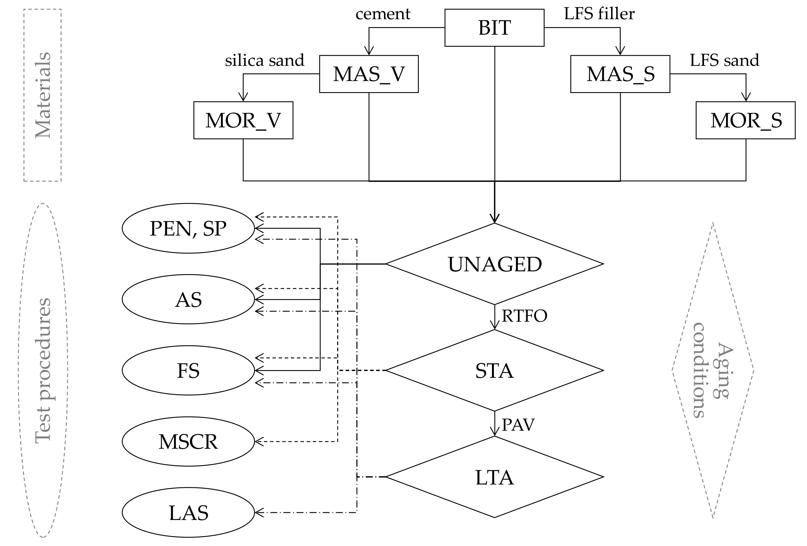
Figure 3.
Basic consistency properties of test materials.
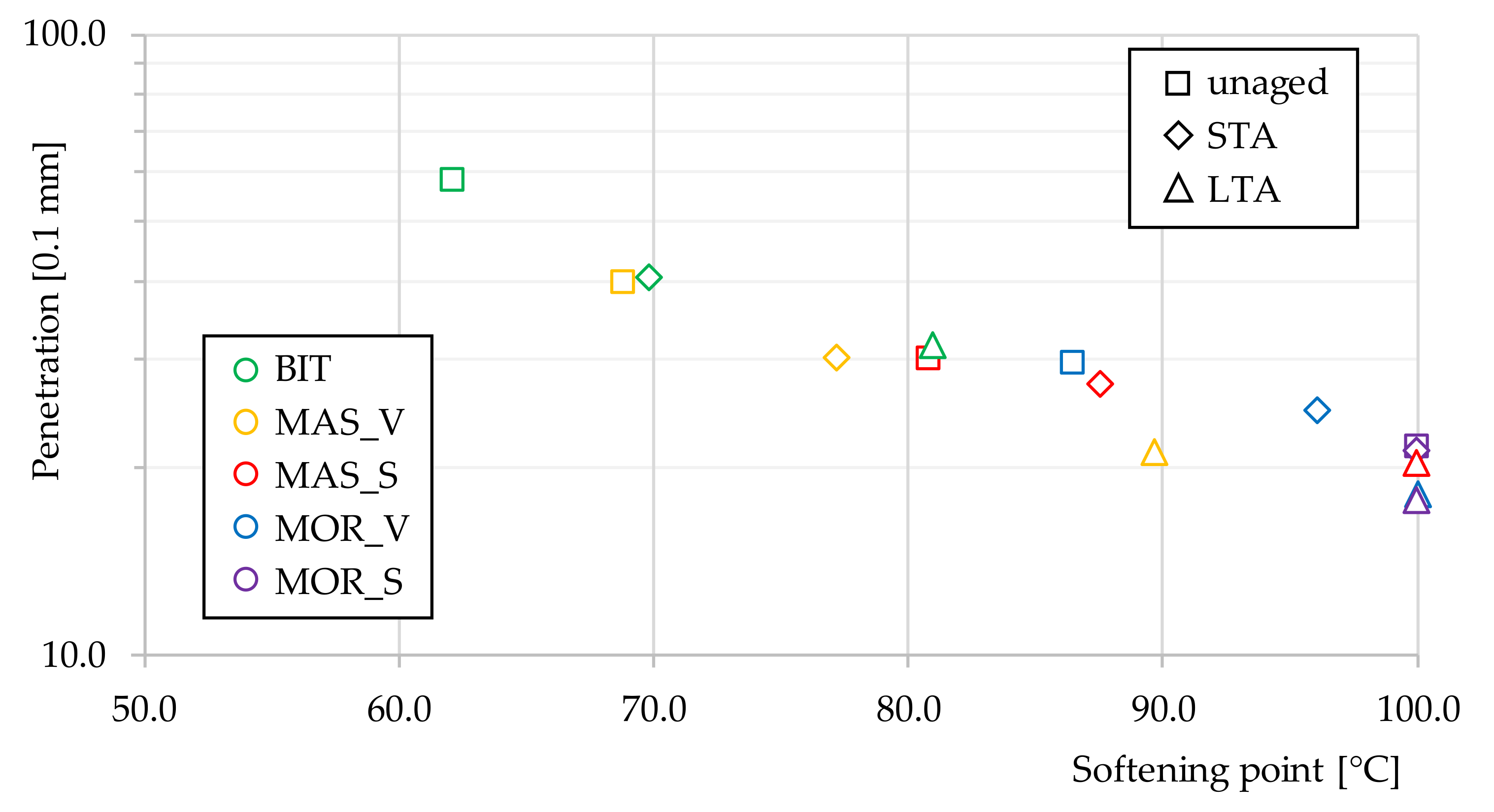
Figure 4.
Amplitude sweep test results for unaged blends (test frequency = 10 rad/s).
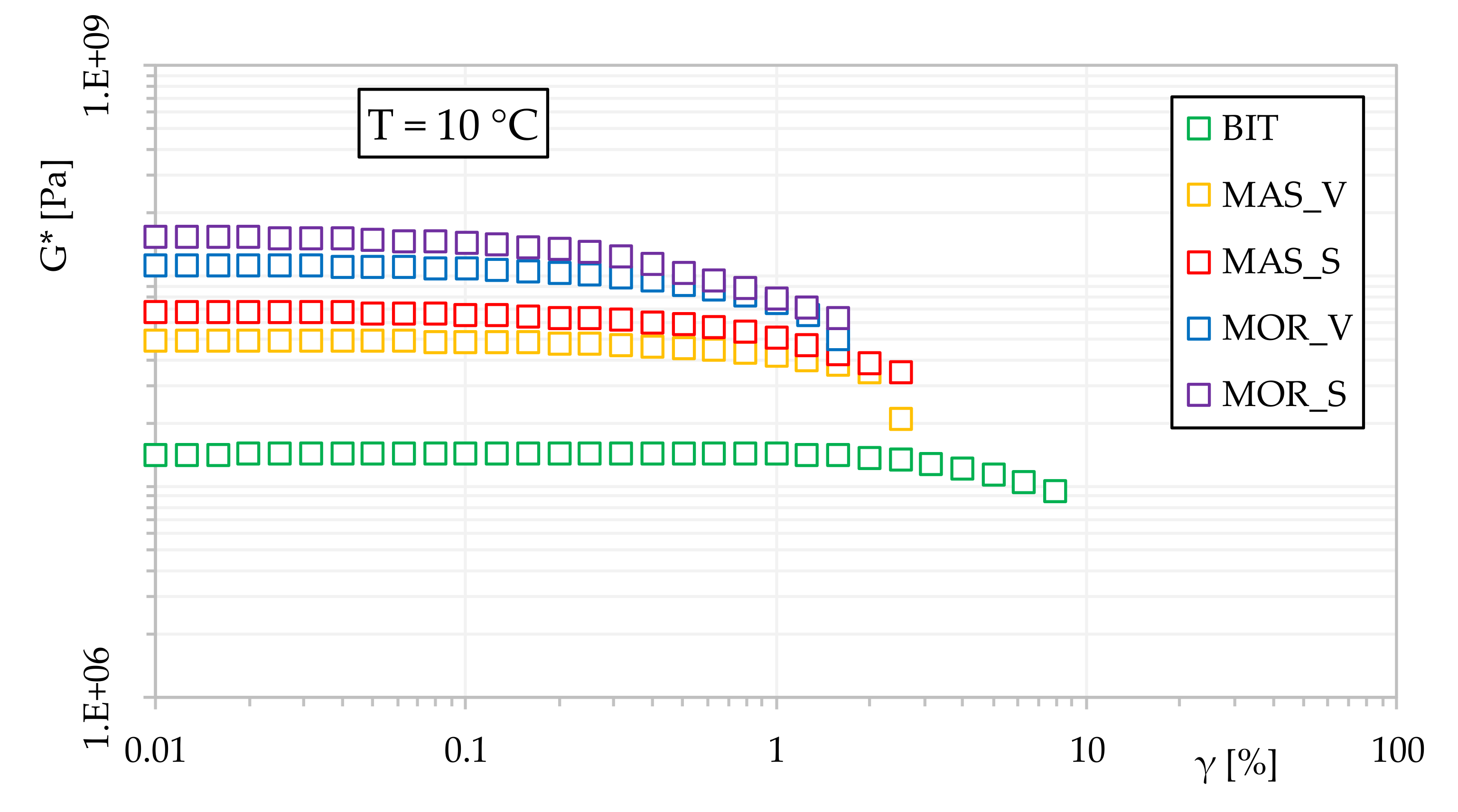
Figure 5.
LVE properties of LTA materials in Black (a) and Cole-Cole (b) spaces.
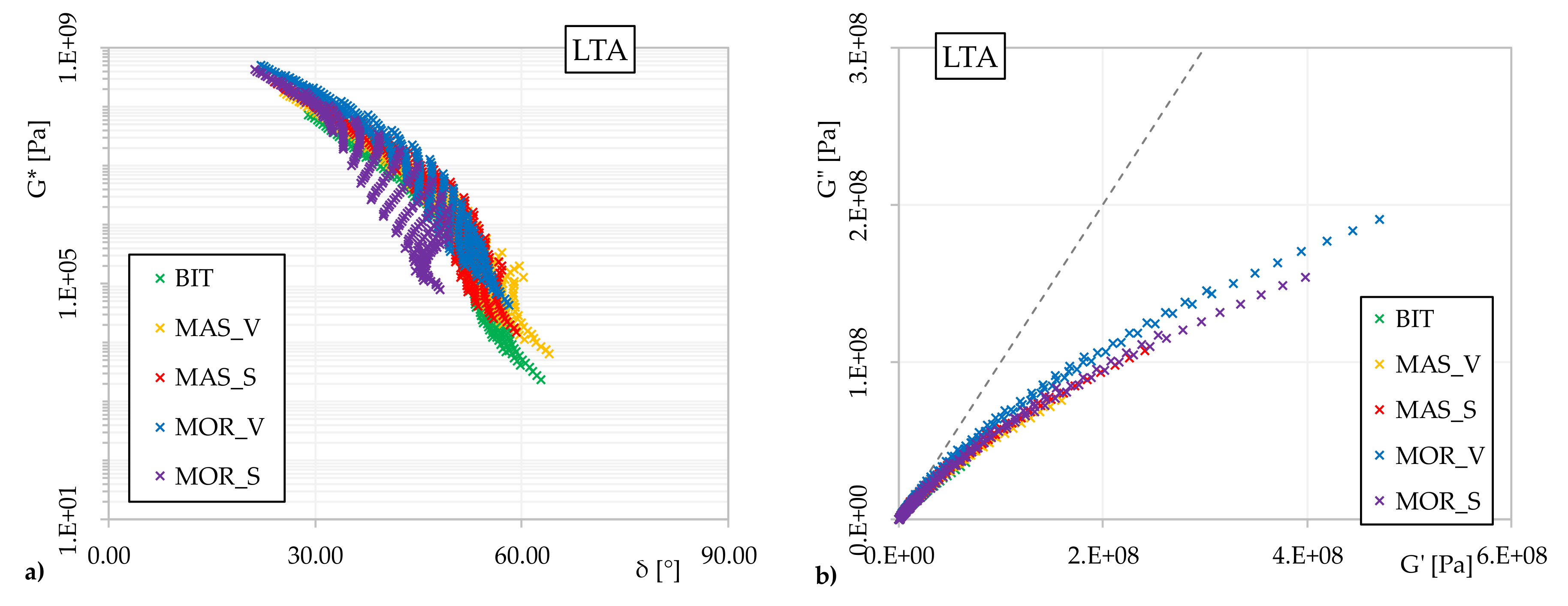
Figure 6.
G* master curve (a) and shift factors evolution (b) for LTA materials (Tref = 20 °C).
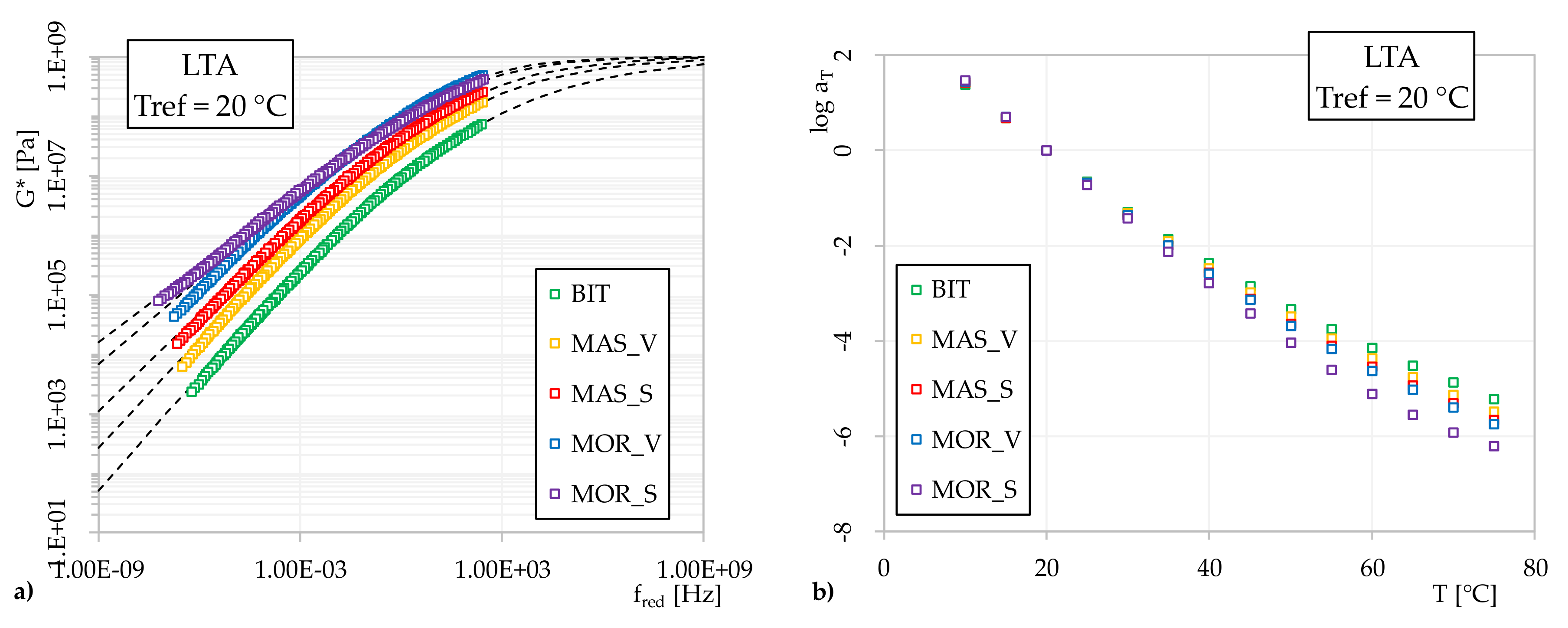
Figure 7.
MSCR test results at 70 °C (STA materials): average percentage recovery R (a); average non-recoverable creep compliance Jnr (b); differences between Jnr at different stress levels Jnr-diff (c).
Figure 7.
MSCR test results at 70 °C (STA materials): average percentage recovery R (a); average non-recoverable creep compliance Jnr (b); differences between Jnr at different stress levels Jnr-diff (c).

Figure 8.
Fatigue lines from LAS test results (LTA materials).


Table 1.
Main properties of the PMB 45/80-60 asphalt binder.
| Characteristic | Test Method | Value |
|---|---|---|
| Penetration at 25 °C | EN 1426 | 58.2 × 0.1 mm |
| Softening point | EN 1427 | 62.1 °C |
| Ductility at 5 °C | ASTM D113 | 170 mm |
| Dynamic viscosity at 100 °C | EN 13702 | 17.5 Pa×s |
| Dynamic viscosity at 150 °C | EN 13702 | 0.8 Pa×s |
| Residue after short-term aging (EN 12607-1) | ||
| Retained penetration at 25 °C | EN 1426 | 69.9% |
| Increase in softening point | EN 1427 | 7.7 °C |
Table 2.
Basic properties of the selected aggregates.
| Characteristic | Test Method | Silica | Ladle Furnace Slag (LFS) |
|---|---|---|---|
| Bulk density | EN 1097-6 | 2.74 g/cm3 | 2.83 g/cm3 |
| Fineness modulus | EN 933-1 | 2.9 | 4.2 |
| Blaine specific surface | EN 196-6 | - | 2654–3091 cm2/g |
| Sand equivalent | EN 933-8 | 78% | 50% |
| Plasticity Index | CEN ISO/TS 17892-12 | Non-plastic | Non-plastic |
Table 3.
Chemical composition of the LFS.
| CaO | SiO2 | MgO | Al2O3 | Fe2O3 | MnO | |
|---|---|---|---|---|---|---|
| LFS [% by weight] | 56.7 | 17.7 | 9.6 | 6.6 | 2.2 | 0.3 |
Table 4.
Tested materials.
| Material ID | Bitumen | Filler | Fine Sand |
|---|---|---|---|
| Bitumen (BIT) | PMB 45/80-60 | - | - |
| MAStic with Virgin aggregate (MAS_V) | PMB 45/80-60 | Cement | - |
| MAStic with LFS aggregate (MAS_S) | PMB 45/80-60 | LFS | - |
| MORtar with Virgin aggregates (MOR_V) | PMB 45/80-60 | Cement | Silica |
| MORtar with LFS aggregates (MOR_S) | PMB 45/80-60 | LFS | LFS |
Table 5.
Linear viscoelastic LVE limit (γlimit) of test materials at 10 °C (test frequency = 10 rad/s).
Table 5.
Linear viscoelastic LVE limit (γlimit) of test materials at 10 °C (test frequency = 10 rad/s).
| Material | Aging | Initial G* [Pa] | γlimit [%] |
|---|---|---|---|
| BIT | Unaged | 1.11 107 | 2.00 |
| Short-term aged (STA) | 1.45 107 | 2.00 | |
| Long-term aged (LTA) | 3.20 107 | 1.80 | |
| MAS_V | Unaged | 4.93 107 | 0.40 |
| Short-term aged (STA) | 6.32 107 | 0.36 | |
| Long-term aged (LTA) | 9.04 107 | 0.28 | |
| MAS_S | Unaged | 6.36 107 | 0.17 |
| Short-term aged (STA) | 6.78 107 | 0.16 | |
| Long-term aged (LTA) | 1.54 108 | 0.14 | |
| MOR_V | Unaged | 9.17 107 | 0.16 |
| Short-term aged (STA) | 1.12 108 | 0.15 | |
| Long-term aged (LTA) | 1.56 108 | 0.07 | |
| MOR_S | Unaged | 1.05E 108 | 0.09 |
| Short-term aged (STA) | 1.21E 108 | 0.08 | |
| Long-term aged (LTA) | 2.02E 108 | 0.05 |
Table 6.
Shift factors and G* master curve model parameters (reference temperature = 20 °C).
| Material | Aging | C1 | C2 | fc [Hz] | k | me | R |
|---|---|---|---|---|---|---|---|
| BIT | Unaged | 13.7 | 104.1 | 263.1 | 0.19 | 0.85 | 1.35 |
| STA | 15.2 | 114.3 | 145.4 | 0.16 | 0.81 | 1.53 | |
| LTA | 17.5 | 129.0 | 120.3 | 0.16 | 0.66 | 1.23 | |
| MAS_V | Unaged | 13.5 | 105.7 | 131.5 | 0.22 | 0.77 | 1.09 |
| STA | 14.7 | 115.2 | 106.3 | 0.21 | 0.71 | 1.02 | |
| LTA | 19.5 | 139.8 | 71.1 | 0.19 | 0.61 | 0.97 | |
| MAS_S | Unaged | 13.8 | 107.0 | 109.5 | 0.25 | 0.76 | 0.92 |
| STA | 14.6 | 113.1 | 95.7 | 0.24 | 0.70 | 0.89 | |
| LTA | 20.4 | 141.1 | 69.5 | 0.22 | 0.55 | 0.74 | |
| MOR_V | Unaged | 14.7 | 106.4 | 157.9 | 0.29 | 0.65 | 0.67 |
| STA | 19.4 | 138.1 | 129.2 | 0.30 | 0.51 | 0.52 | |
| LTA | 21.4 | 147.8 | 79.5 | 0.30 | 0.48 | 0.48 | |
| MOR_S | Unaged | 15.1 | 109.1 | 130.1 | 0.31 | 0.60 | 0.58 |
| STA | 16.5 | 125.3 | 94.6 | 0.29 | 0.48 | 0.50 | |
| LTA | 25.4 | 163.2 | 75.3 | 0.29 | 0.43 | 0.45 |
Table 7.
Summary of MSCR test results (STA materials).
| Material | Temperature [°C] | τ = 0.1 kPa | τ = 3.2 kPa | τ = 10 kPa | |||||
|---|---|---|---|---|---|---|---|---|---|
| R [%] | Jnr [1/kPa] | R [%] | Jnr [1/kPa] | Jnr-diff 1 [%] | R [%] | Jnr [1/kPa] | Jnr-diff 2 [%] | ||
| BIT | 50 | 72 | 0.03 | 71.7 | 0.03 | 1.2 | - | - | - |
| 60 | 62.4 | 0.13 | 58.8 | 0.15 | 11.9 | - | - | - | |
| 70 | 46.2 | 0.6 | 31 | 0.84 | 40.5 | - | - | - | |
| 80 | 26.1 | 2.49 | 6.1 | 4.02 | 61.5 | - | - | - | |
| MAS_V | 50 | - | - | - | - | - | - | - | - |
| 60 | 64.3 | 0.02 | 59.3 | 0.03 | 13.3 | 52.8 | 0.03 | 18.2 | |
| 70 | 48.7 | 0.1 | 36.5 | 0.13 | 23.2 | 24.6 | 0.17 | 27.4 | |
| 80 | 28.9 | 0.43 | 12.8 | 0.59 | 36.9 | 5.9 | 0.75 | 31.1 | |
| MAS_S | 50 | - | - | - | - | - | - | - | - |
| 60 | 65.5 | 0.01 | 59.1 | 0.01 | 4.4 | 53 | 0.01 | 6.3 | |
| 70 | 50.5 | 0.04 | 37.3 | 0.05 | 16.2 | 26.9 | 0.05 | 11 | |
| 80 | 32.4 | 0.14 | 17 | 0.18 | 20.9 | 8.6 | 0.2 | 36.4 | |
| MOR_V | 50 | - | - | - | - | - | - | - | - |
| 60 | - | - | - | - | - | - | - | - | |
| 70 | 69.3 | <0.01 | 45.5 | 0.02 | 22.7 | 32.8 | 0.02 | 6.7 | |
| 80 | 66 | 0.01 | 27.4 | 0.02 | 35.6 | 16.5 | 0.03 | 10.8 | |
| MOR_S | 50 | - | - | - | - | - | - | - | - |
| 60 | - | - | - | - | - | - | - | - | |
| 70 | 63.5 | <0.01 | 44.7 | 0.01 | 5.6 | 39.7 | 0.01 | 2.8 | |
| 80 | 60.9 | 0.01 | 38 | 0.01 | 7.9 | 30.9 | 0.02 | 7.7 | |
1; 2.
Table 8.
Summary of LAS test results and selected LVE properties (LTA materials).
| Material | A | B | γ 6[%] | G* (20 °C; 10 Hz) 1 [Pa] | δ (20 °C; 10 Hz) 1 [deg] |
|---|---|---|---|---|---|
| BIT | 22,687 | 4.179 | 0.40 | 2.42 107 | 36.67 |
| MAS_V | 54.2 | 4.496 | 0.11 | 6.37 107 | 33.28 |
| MAS_S | 2.75 | 5.004 | 0.08 | 1.01 108 | 32.01 |
| MOR_V | 0.45 | 4.923 | 0.05 | 2.09 108 | 29.75 |
| MOR_S | 0.28 | 4.946 | 0.05 | 1.75 108 | 28.48 |
1 from Frequency Sweeps (FS).
© 2020 by the authors. Licensee MDPI, Basel, Switzerland. This article is an open access article distributed under the terms and conditions of the Creative Commons Attribution (CC BY) license (http://creativecommons.org/licenses/by/4.0/).
Share and Cite
MDPI and ACS Style
Pasetto, M.; Baliello, A.; Pasquini, E.; Skaf, M.; Ortega-López, V. Performance-Based Characterization of Bituminous Mortars Prepared With Ladle Furnace Steel Slag. Sustainability 2020, 12, 1777. https://doi.org/10.3390/su12051777
AMA Style
Pasetto M, Baliello A, Pasquini E, Skaf M, Ortega-López V. Performance-Based Characterization of Bituminous Mortars Prepared With Ladle Furnace Steel Slag. Sustainability. 2020; 12(5):1777. https://doi.org/10.3390/su12051777
Chicago/Turabian StylePasetto, Marco, Andrea Baliello, Emiliano Pasquini, Marta Skaf, and Vanesa Ortega-López. 2020. "Performance-Based Characterization of Bituminous Mortars Prepared With Ladle Furnace Steel Slag" Sustainability 12, no. 5: 1777. https://doi.org/10.3390/su12051777
Note that from the first issue of 2016, this journal uses article numbers instead of page numbers. See further details here.