Figure 1.
Scheme of the applied methodology.
Figure 1.
Scheme of the applied methodology.
Figure 2.
The town hall of Campobasso: (a) North-East façade, (b) South-West façade, (c) top view of the building and (d) old view of the building.
Figure 2.
The town hall of Campobasso: (a) North-East façade, (b) South-West façade, (c) top view of the building and (d) old view of the building.
Figure 3.
Plant room (
a), boiler regulation curve (
b) [
29].
Figure 3.
Plant room (
a), boiler regulation curve (
b) [
29].
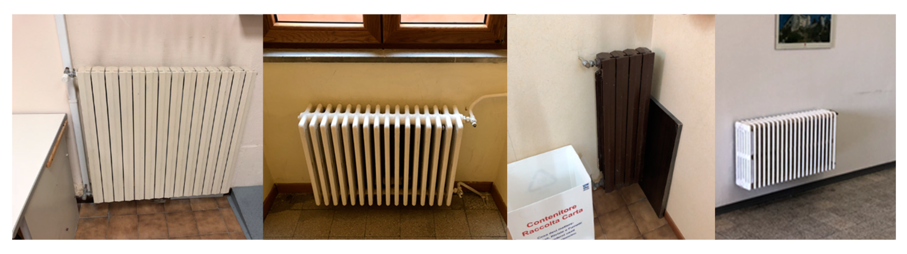
Figure 4.
Several types of radiators [
29].
Figure 4.
Several types of radiators [
29].
Figure 5.
Several types of lamps [
29].
Figure 5.
Several types of lamps [
29].
Figure 6.
Monthly (bars) and average electricity demand (red circles) for the years 2016, 2017, 2018.
Figure 6.
Monthly (bars) and average electricity demand (red circles) for the years 2016, 2017, 2018.
Figure 7.
Monthly (bars) and average natural gas demand (red circles) for the years 2015 (from October to December) 2016, 2017, 2018 (until April).
Figure 7.
Monthly (bars) and average natural gas demand (red circles) for the years 2015 (from October to December) 2016, 2017, 2018 (until April).
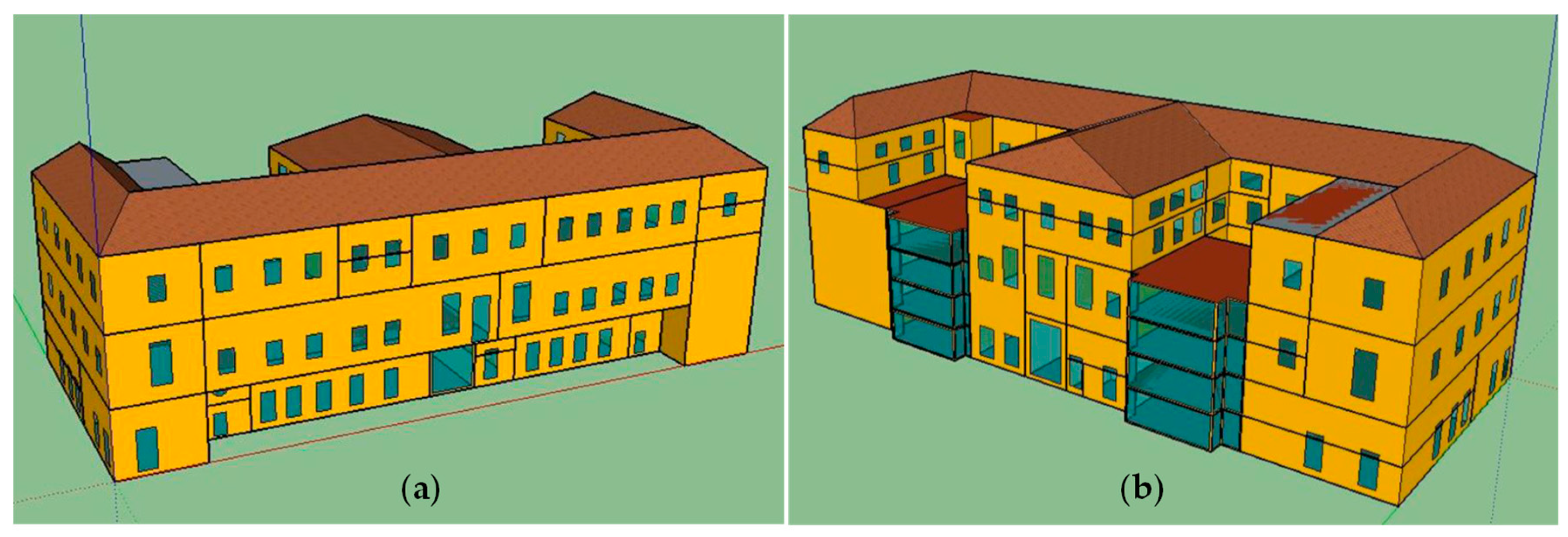
Figure 8.
3D sketch of Palazzo San Giorgio: north (a) and south view (b).
Figure 8.
3D sketch of Palazzo San Giorgio: north (a) and south view (b).
Figure 9.
Simulated and billed (on average) monthly electricity demand in MWh and monthly errors (ERRmonth) in percentage.
Figure 9.
Simulated and billed (on average) monthly electricity demand in MWh and monthly errors (ERRmonth) in percentage.
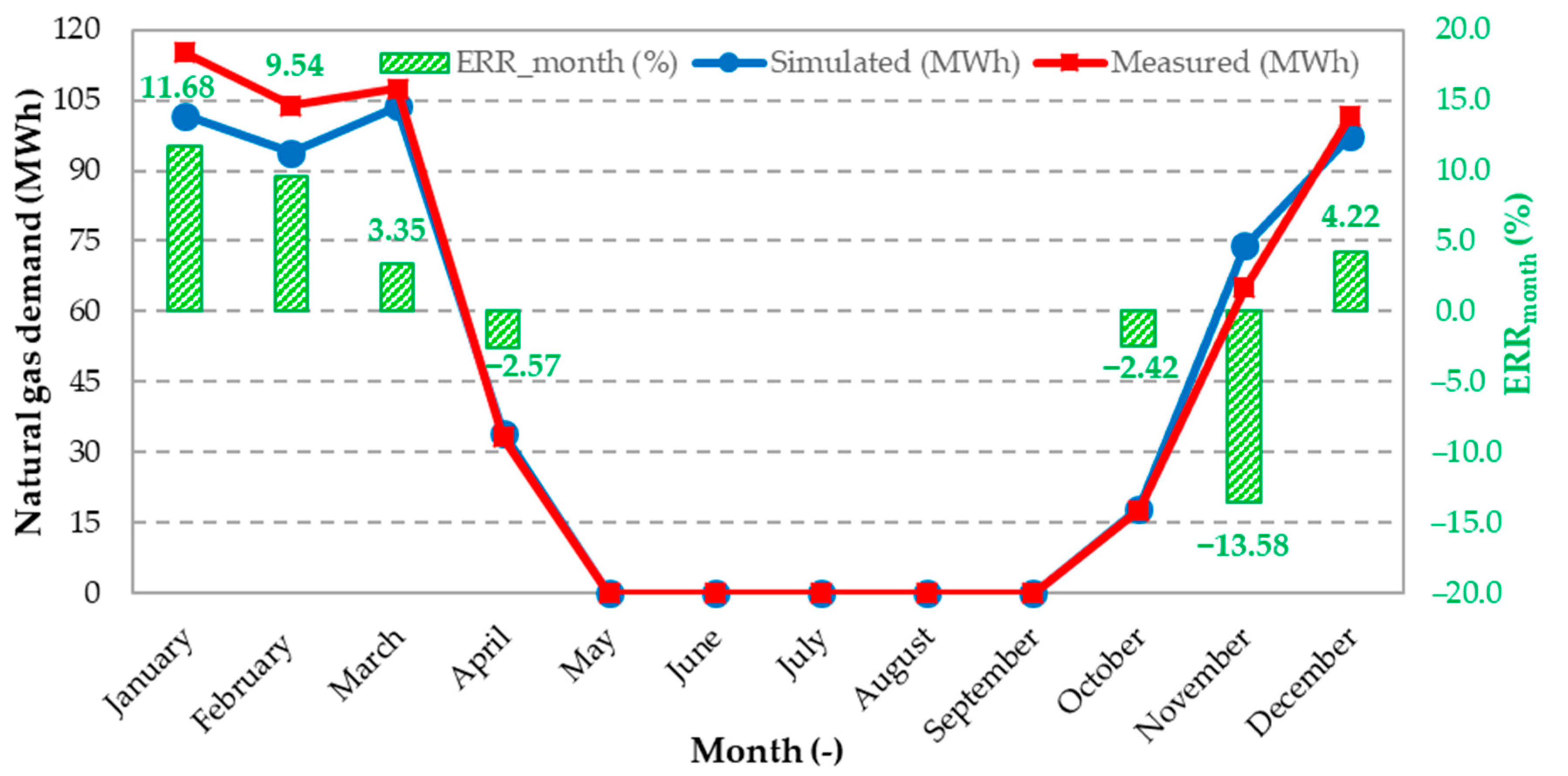
Figure 10.
Simulated and billed (on average) monthly natural gas energy demand expressed in MWh and monthly errors (ERRmonth) in percentage.
Figure 10.
Simulated and billed (on average) monthly natural gas energy demand expressed in MWh and monthly errors (ERRmonth) in percentage.
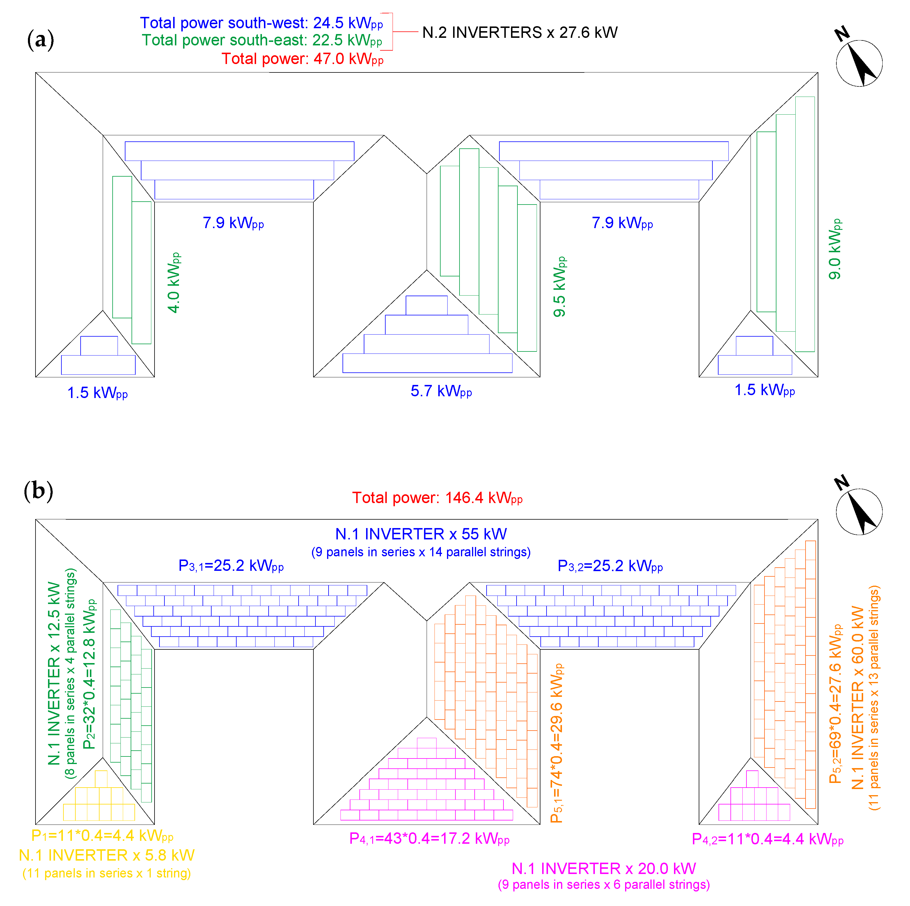
Figure 11.
Simplified scheme of the PV-I (a) and PV-HE (b).
Figure 11.
Simplified scheme of the PV-I (a) and PV-HE (b).
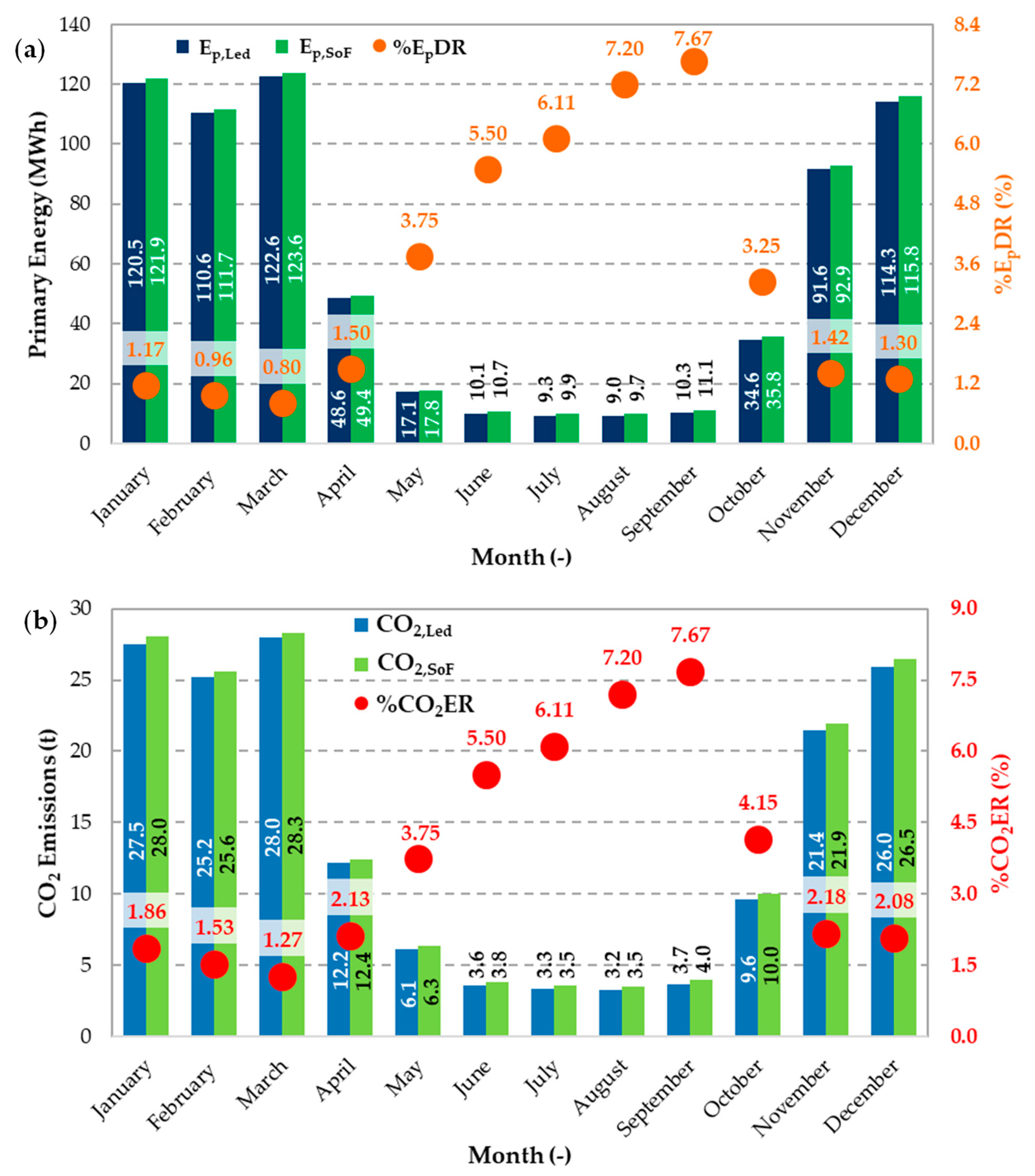
Figure 12.
(a) Primary energy comparison (blue and green bars) and percentage primary energy demand reduction (orange circles), (b) CO2 emissions (light blue and green bars) end percentage reduction (red circles) between Led lamps and SoF on a monthly basis.
Figure 12.
(a) Primary energy comparison (blue and green bars) and percentage primary energy demand reduction (orange circles), (b) CO2 emissions (light blue and green bars) end percentage reduction (red circles) between Led lamps and SoF on a monthly basis.
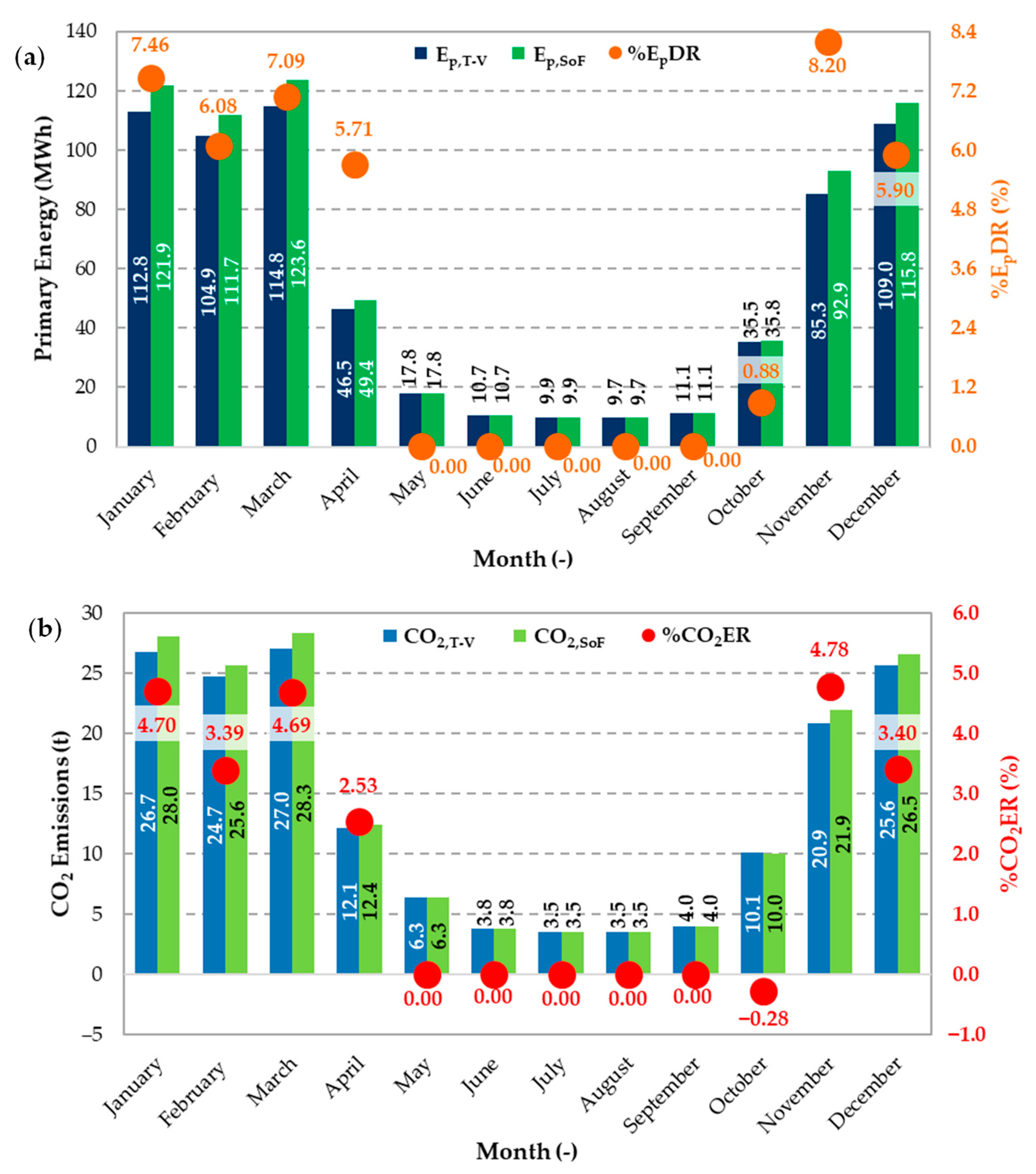
Figure 13.
(a) Primary energy comparison (blue and green bars) and percentage primary energy demand reduction (orange circles), (b) CO2 emissions (light blue and green bars) end percentage reduction (red circles) between Thermostatic Valves (T-V) and SoF on a monthly basis.
Figure 13.
(a) Primary energy comparison (blue and green bars) and percentage primary energy demand reduction (orange circles), (b) CO2 emissions (light blue and green bars) end percentage reduction (red circles) between Thermostatic Valves (T-V) and SoF on a monthly basis.
Figure 14.
(a) Primary energy comparison (blue and green bars) and percentage primary energy demand reduction (orange circles), (b) CO2 emissions (light blue and green bars) end percentage reduction (red circles) between cogenerators and SoF on a monthly basis.
Figure 14.
(a) Primary energy comparison (blue and green bars) and percentage primary energy demand reduction (orange circles), (b) CO2 emissions (light blue and green bars) end percentage reduction (red circles) between cogenerators and SoF on a monthly basis.
Figure 15.
Electricity balance considering CHP electricity production, Fraction of Load Met (FLM, solid red circles) and index of on-site use (Ios,u, solid blue rhombus). In each stack: the dark green textured bars represent the electric energy fed into the grid (Eel,tg), the light green textured bars the electric energy used on-site (Eel,os), the gray textured bars the electricity taken the grid (Eel,tg).
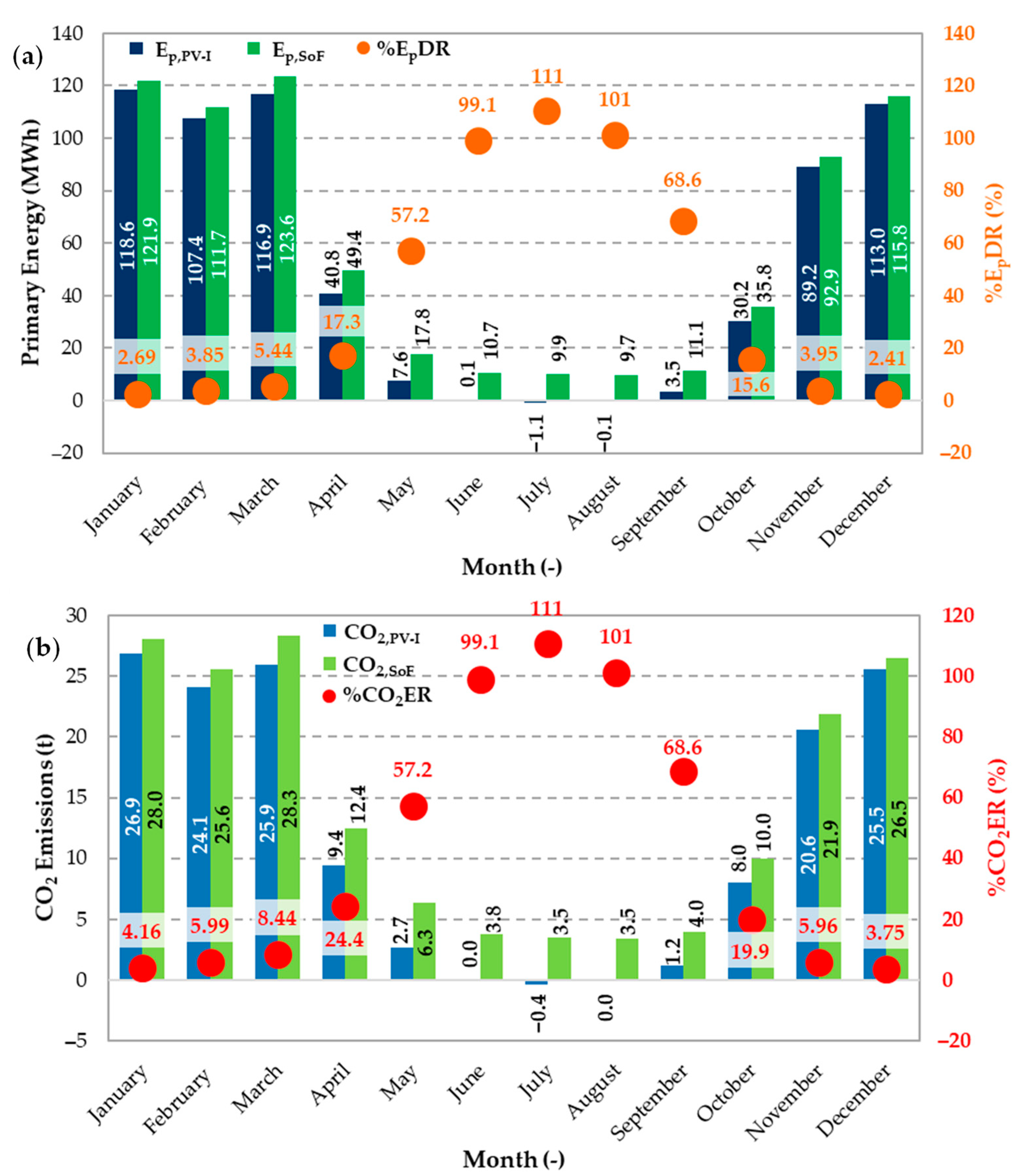
Figure 16.
(a) Primary energy comparison (blue and green bars) and percentage primary energy demand reduction (orange circles), (b) CO2 emissions (light blue and green bars) end percentage reduction (red circles) between PV-I and SoF on a monthly basis.
Figure 16.
(a) Primary energy comparison (blue and green bars) and percentage primary energy demand reduction (orange circles), (b) CO2 emissions (light blue and green bars) end percentage reduction (red circles) between PV-I and SoF on a monthly basis.
Figure 17.
(a) Primary energy comparison (blue and green bars) and percentage primary energy demand reduction (orange circles), (b) CO2 emissions (light blue and green bars) end percentage reduction (red circles) between PV-HE and SoF on a monthly basis.
Figure 17.
(a) Primary energy comparison (blue and green bars) and percentage primary energy demand reduction (orange circles), (b) CO2 emissions (light blue and green bars) end percentage reduction (red circles) between PV-HE and SoF on a monthly basis.
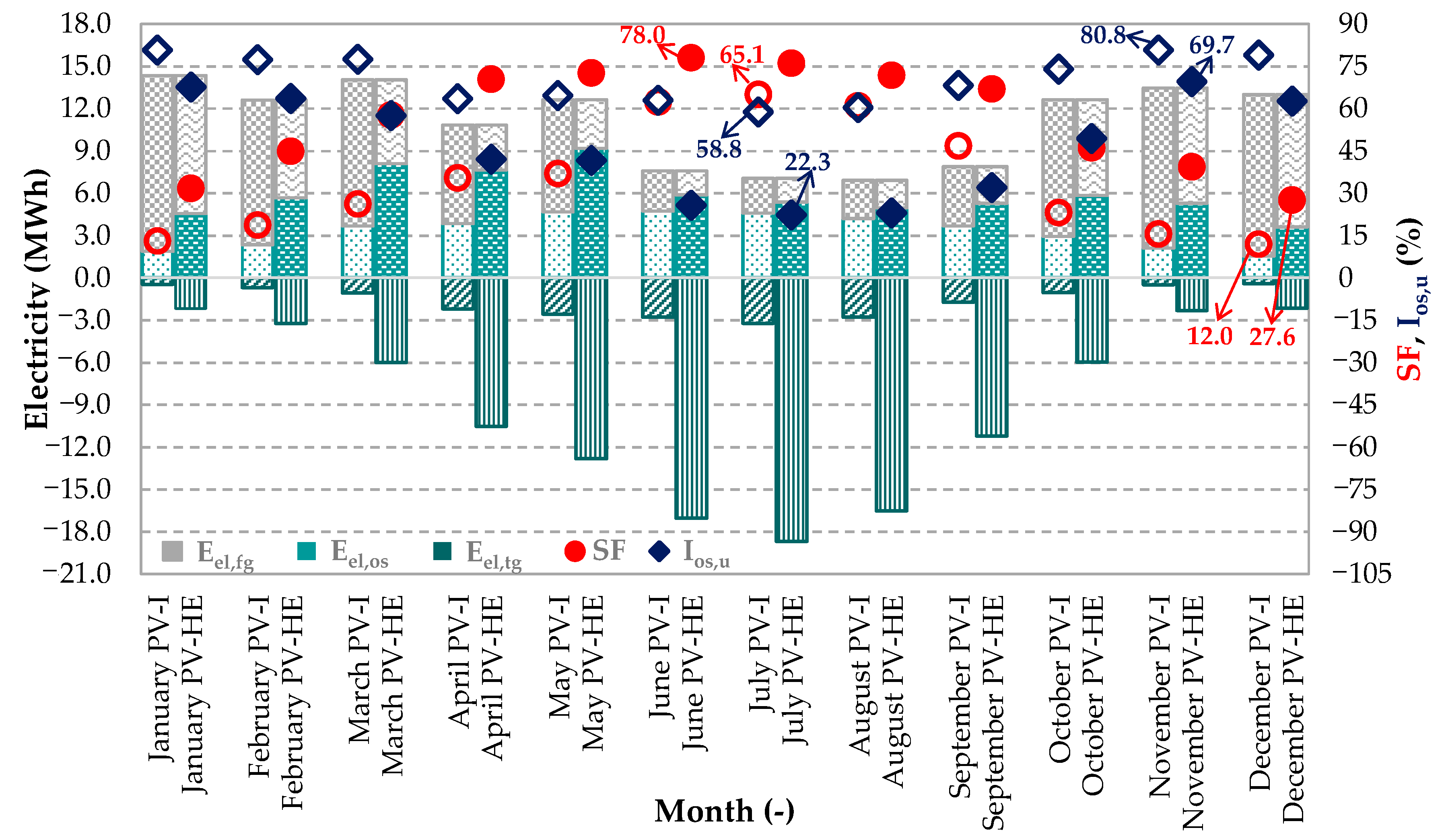
Figure 18.
Electricity balance considering PV electricity production, Solar Fraction (SF) and index of on-site use (Ios,u). In each block of bars (one per month): the first stack refers to PV-I, the second one to PV-HE, while in each stack: the dark green textured bars represent the electric energy fed into the grid (Eel,tg), the light green textured bars the electric energy used on-site (Eel,os), the gray textured bars the electricity taken the grid (Eel,tg). Instead, the solid symbols (circle and rhombus) refer to PV-HE while the empty ones to PV-I.
Figure 19.
(a) Primary energy comparison (blue and green bars) and percentage primary energy demand reduction (orange circles), (b) CO2 emissions (light blue and green bars) end percentage reduction (red circles) between CR-PV-I and SoF on a monthly basis.
Figure 19.
(a) Primary energy comparison (blue and green bars) and percentage primary energy demand reduction (orange circles), (b) CO2 emissions (light blue and green bars) end percentage reduction (red circles) between CR-PV-I and SoF on a monthly basis.
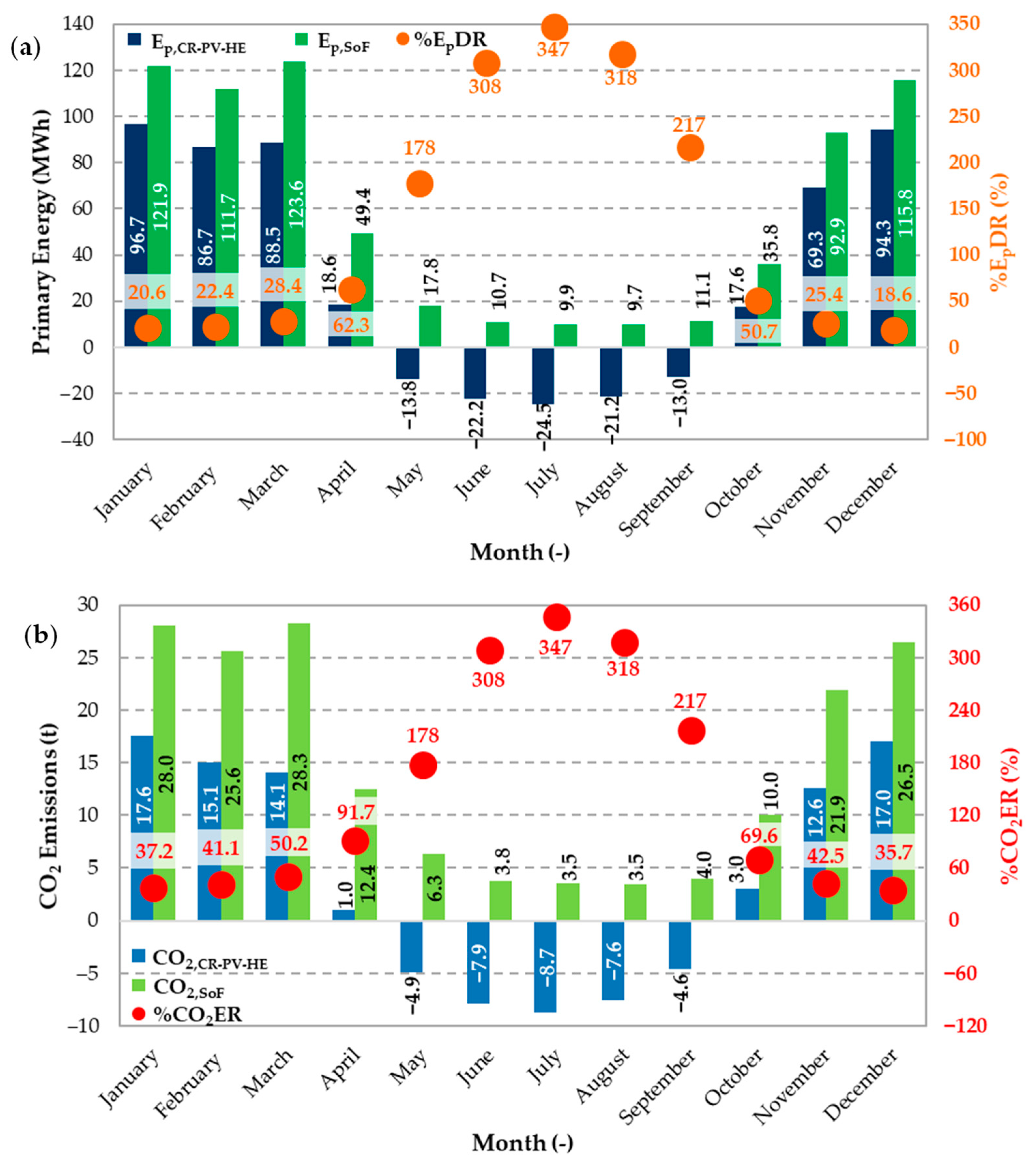
Figure 20.
(a) Primary energy comparison (blue and green bars) and percentage primary energy demand reduction (orange circles), (b) CO2 emissions (light blue and green bars) end percentage reduction (red circles) between CR-PV-HE and SoF on a monthly basis.
Figure 20.
(a) Primary energy comparison (blue and green bars) and percentage primary energy demand reduction (orange circles), (b) CO2 emissions (light blue and green bars) end percentage reduction (red circles) between CR-PV-HE and SoF on a monthly basis.
Figure 21.
Electricity balance considering electricity production in the combined interventions, Fraction of Load Met (FLM) and index of on-site use (Ios,u). In each block of bars (one per month): the first stack refers to CR-PV-I, the second one to CR-PV-HE, while in each stack: the dark green textured bars represent the electric energy fed into the grid (Eel,tg), the light green textured bars the electric energy used on-site (Eel,os), the gray textured bars the electricity taken the grid (Eel,tg). Instead, the solid symbols (circle and rhombus) refer to CR-PV-HE while the empty ones to CR-PV-I.
Figure 22.
Energy analysis representation in terms of primary energy shares (gray and blue bars) and percentage demand reduction (orange circles) on an annual basis.
Figure 22.
Energy analysis representation in terms of primary energy shares (gray and blue bars) and percentage demand reduction (orange circles) on an annual basis.
Figure 23.
Environmental analysis representation in terms of CO2 emissions shares (light blue and gray bars) and percentage emissions reduction (red circles) on an annual basis.
Figure 23.
Environmental analysis representation in terms of CO2 emissions shares (light blue and gray bars) and percentage emissions reduction (red circles) on an annual basis.
Table 1.
Working hour schedule.
Table 1.
Working hour schedule.
| Day | Working Hours |
|---|
| Monday—Wednesday—Friday | 08:30–14:00 |
| Tuesday—Thursday | 08:30–14:00 and 15:00–18:00 |
| Saturday | 08:00–14:00 (only few people) |
| Sunday | Closed |
Table 2.
Heating system daily operation periods.
Table 2.
Heating system daily operation periods.
| Weekday | ON Period |
|---|
| Monday—Wednesday—Friday—Saturday | 06:00–13:00 |
| Tuesday—Thursday | 06:00–12:30 and 14:30–18:30 |
Table 3.
Building main representative information.
Table 3.
Building main representative information.
| Data | Values |
|---|
| Number of floors | 3 + 3 mezzanine floors |
| Number of rooms (including offices, council room, user room, meeting room, toilets) | 101 |
| Number of working stations | 144 |
| Radiators number | 143 |
| Radiators estimated power (kW) | 373.5 |
| Supplementary electric heater number | 63 |
| Lamps number (including neon, halogen, incandescent and led) | 366 |
| Lamps estimated power (including neon, halogen, incandescent and led) (kW) | 29.4 |
| Number of printers | 50 |
| PC number | 132 |
| Estimated PC and printers power (kW) | 39.4 |
Table 4.
Time slots for electricity billing.
Table 4.
Time slots for electricity billing.
| Time Slot Acronym | Period |
|---|
| F1 | From 08:00 to 19:00 in the weekdays |
| F2 | From 07:00 to 08:00 and from 19:00–23:00 in the weekdays, from 07:00 to 23:00 on Saturday |
| F3 | The remaining period and holidays |
Table 5.
Calibration indexes.
Table 5.
Calibration indexes.
| |
(%)
| MBE
(%) | Cv(RMSE)
(%) |
|---|
| Electricity demand | −1.79 | −2.63 | 6.87 |
| Gas demand | 3.88 | 1.46 | 9.60 |
| Limits | ±10 | ±5 | ±10 |
Table 6.
Synthesis of the renovation actions and their abbreviations.
Table 6.
Synthesis of the renovation actions and their abbreviations.
| Action | Abbreviation |
|---|
| Replacement of existing lamps with led | Led |
| Adoption of thermostatic valves | T-V |
| Installation of cogenerators and storage tanks | Cog |
| Introduction of an integrated photovoltaic system | PV-I |
| Introduction of a high efficiency photovoltaic system | PV-HE |
| Combined renovation with PV-I | CR-PV-I |
| Combined renovation with PV-HE | CR-PV-HE |
Table 7.
Main rated characteristics of cogenerators [
36].
Table 7.
Main rated characteristics of cogenerators [
36].
| Characteristics | Values |
|---|
| Net electrical base load power | 43 kW |
| Thermal capacity | 90 kW |
| Natural gas consumption | 14.8 m3/h |
| Exhaust gas flow rate | 188 kg/h |
| Thermal power recovery from exhaust | 27 kW |
| Electrical efficiency | 30% |
| Thermal efficiency | 63% |
| Generator efficiency | 91.2% |
| Engine type | 8V—Otto cycle |
Table 8.
Main rated characteristics of integrated photovoltaic elements [
38].
Table 8.
Main rated characteristics of integrated photovoltaic elements [
38].
| Characteristics | Values |
|---|
| Rated power | 45 Wpp |
| Rated voltage | 5.76 V |
| Rated current | 7.81 A |
| Open circuit voltage | 7.51 V |
| Short circuit current | 8.09 A |
| Temperature coefficient of short circuit current | 4.28 mA/°C |
| Temperature coefficient of open circuit voltage | −0.026 V/°C |
| NOCT * | 41.73 °C |
| length | 2.25 m |
| width | 16.7 cm |
| Number of cells | 12 |
Table 9.
Main rated characteristics of high efficiency photovoltaic panels [
40].
Table 9.
Main rated characteristics of high efficiency photovoltaic panels [
40].
| Characteristics | Values |
|---|
| Rated power | 400 Wpp |
| Rated voltage | 65.8 V |
| Rated current | 6.08 A |
| Open circuit voltage | 75.6 V |
| Short circuit current | 6.58 A |
| Temperature coefficient of short circuit current | 4.28 mA/°C |
| Temperature coefficient of open circuit voltage | −176.8 mV/°C |
| NOCT * | 45.0 °C |
| length | 1.69 m |
| width | 1.05 cm |
| Number of cells | 104 |
Table 10.
Rated characteristics of inverters used in action PV-HE.
Table 10.
Rated characteristics of inverters used in action PV-HE.
| | Inverter 1
[41] | Inverter 2
[42] | Inverter 3
[43] | Inverter 4
[39] | Inverter 5
[44] |
|---|
| Nominal power (kW) | 5.8 | 12.5 | 55.0 | 20.0 | 60.0 |
| Maximum efficiency (%) | 98.0 | 97.8 | 96.3 | 98.2 | 98.5 |

 ,
, 


