A Case Study on Large Deformation Failure Mechanism and Control Techniques for Soft Rock Roadways in Tectonic Stress Areas

1
State Key Laboratory of Coal Resources and Safe Mining, China University of Mining and Technology, Xuzhou 221116, China
2
School of Coal Engineering, Shanxi Datong University, Datong 037003, China
*
Authors to whom correspondence should be addressed.
Sustainability 2019, 11(13), 3510; https://doi.org/10.3390/su11133510
Submission received: 13 May 2019
/
Revised: 16 June 2019
/
Accepted: 24 June 2019
/
Published: 26 June 2019
(This article belongs to the Section Sustainable Engineering and Science)
Abstract
:Large deformation and failure of soft rock are pressing problems in the mining practice. This paper provides a case study on failure mechanisms and support approaches for a water-rich soft rock roadway in tectonic stress areas of the Wangzhuang coal mine, China. Mechanic properties of rock mass related to the roadway are calibrated via a geological strength index method (GSI), based on which a corresponding numerical simulation model is established in the Universal Discrete Element Code (UDEC) software. The failure mechanism of the roadway under water-saturating and weathering conditions is revealed by field tests and numerical simulation. It is found that the stress evolution and crack development are affected by weathering and horizontal tectonic stresses. The roadway roof and floor suffer from high stress concentration and continuous cracking, and are consequently seen with rock failure, strength weakening, and pressure relief. Unfortunately, the current support system fails to restrain rock weathering and strength weakening, and the roadway is found with serious floor heave, roof subsidence, and large asymmetric deformation. Accordingly, a new combined support system of “bolt–cable–mesh–shotcrete + grouting” is proposed. Moreover, numerical simulation and field testing are conducted to validate the feasibility and effectiveness of the proposed approach, the results of which demonstrate the capacity of the proposed new support method to perfectly control the surrounding rock. Findings of this research can provide valuable references for support engineering in the soft rock roadway under analogous geological conditions.
1. Introduction
In 2018, China’s coal production reached 3.68 billion tons, growing by 4.5% every year [1]. Tremendous coal production pressures force many coal mines to shift into deep-buried coal seams and those with inferior occurrence conditions. Compared with those coal seams with superior occurrence conditions, rock masses with deep burial depth or under complex geological conditions are subjected to extreme in situ stresses and are, thus, prone to creep and long-term large deformation [2]. In the coal mining practice, operation passages such as roadways are usually placed near coal beds or adjacent sedimentary formations such as mudstones and sandstones. In structurally complicated areas, significant and complex in situ stresses and previous geological activities endow rock mass with considerable crack development and extensive fracturing failure, which stimulate challenges in the roadway maintenance. Moreover, loss of confining bed integrity often leads to penetration of water into surrounding rock mass [3]. This intrusion water particularly impacts such sedimentary rock mass [4,5,6], which is embodied as destruction of the sedimentary rock structure and consequent reduction of rock mass strength or cohesion [7]. It is also verified that water can considerably reduce uniaxial compression strengths of sandstone specimens [8]; furthermore, swelling pressures inside rock mass containing swelling components, e.g., montmorillonite and kaolinite, due to water soaking, can promote instability risks of roadway surrounding rocks [9]. In soft rock under such combined effects, a single rock support approach can no longer achieve desirable performance and, hence, it is required to develop surrounding rock control theories and techniques for such large deformation soft rock roadways with respect to actual conditions.
At present, the surrounding rock control technique in the case of large and complex in situ stresses is still a research hotspot, and researchers carried out extensive studies on deformation failure mechanisms [10,11,12], fracture constitutive models [13,14,15,16,17], and surrounding rock control methods [18,19,20] for such roadways. Generally, the soft rock roadway approach can be divided into two types. The first one is to adopt an active support manner with high rigidity and limited flexibility [21], namely the use of a high-strength pre-stressed rock bolt, anchor cable, etc. to provide relatively high supportive resistance for surrounding rocks. The applied pre-stress can enhance the mechanical properties of bolted rock, such as Young’s modulus and cohesion. In this context, a stable load-bearing structure coupling support materials and intrinsic rock mass self-stabilizing strength can be greatly helpful. Such a structure is developed in this study, based on relatively limited deformation and unloading of rock mass. With respect to this philosophy, a novel energy-absorbing bolt with extraordinarily large elongation and constant resistance is also developed [22]. The second approach is a comprehensive support approach, which simultaneously introduces multiple support techniques and achieves surrounding rock control of soft rock roadways in a case-specific manner. On the one hand, methods such as grouting are adopted to improve integrity of fractured surrounding rock and enhance intrinsic rock mass strength [23,24]. On the other hand, support structures such as high-strength rock bolts and cables [20], grid arch frames [25,26], and concrete arch shell [27,28] are combined to serve their own specific functions and, thus, achieve desirable support. In addition, numerous types of combined support systems were adopted to solve large deformation problems of soft rock roadways and were proven to be effective, such as yielding bolt–grouting support [29], combined support with U-shaped steel sets and anchor–grouting [23], support system with square steel confined concrete [30], and combined support with concrete shell and “bolt–cable–mesh–shotcrete” [2].
Although they were well performed, the aforementioned surrounding rock control methods of soft rock roadways are not completely applicable to other support engineering projects with special geological setting, e.g., roadways with high water content in the surrounding rock, which are repeatedly repaired. To solve these problems, this paper takes the -415 traveling roadway of the Wangzhuang coal mine, a high-water-content soft rock roadway penetrating through a syncline, as an example to investigate the large deformation and failure mechanisms of such soft rock roadways and corresponding control methods. Based on rock mass properties calibrated using the geological strength index (GSI) method, a numerical simulation model is established via the Universal Discrete Element Code (UDEC) to investigate the stress and displacement evolutions and fracture propagation. Then, corresponding support strategies and a composite support of “bolt–cable–mesh–shotcrete + grouting” are proposed. Finally, field tests are conducted successfully, which indicate that the combined support system is useful for this type of soft roadway. Findings of this paper are expected to provide valuable references for support practices under analogous geological conditions.
2. Engineering Properties of the -415 Traveling Roadway
2.1. Engineering Setting
The Wangzhuang coal mine is located in Xuzhou City, Jiangsu Province, China (Figure 1a), and production is currently mainly operated in coal bed #7. The -415 traveling roadway serves as the main coal transportation passage for the current mining area. The roadway is constructed in the form of a semicircular arch, with dimensions of 3600 mm × 2900 mm, and penetrates through a syncline structure of the #7 coal roof strata at angles of 6–30° (Figure 1b), successively crawling. Figure 2 shows the lithology of the surrounding rock of the -415 traveling roadway, which successively crawls through medium–fine-grained sandstones, coal–mudstone interbedding layers, mudstone, etc. As a result, the surrounding rock is mainly composed of sandstones and a few sandy mudstones, with formation dip angles in the cross-section of about 9–20°.
The whole length of the roadway is within a complex tectonic stress area formed by the syncline, and there were 23 small faults revealed during its excavation. Cracks in the roadway surrounding rock are rich in crack water, leading to severe water dripping. The primary roadway support adopts U-shaped steel, which was heavily damaged and then repaired using a “bolt–cable–mesh” support system. However, severe deformation failure occurred within six months of repair and the support system can no longer provide satisfactory service.
2.2. Rock Mass Properties
Field in situ stress testing is able to reveal how the geostress is distributed, allowing the comprehensive evaluation of the mechanical status of the roadway surrounding rock. In this study, as shown in Figure 1b, the field in situ stress testing, using the stress relief method, was conducted in a location near the roadway, 20 m away from the opening, and the results were as follows: σH = 20.2 MPa (maximum horizontal principal stress), σh = 17.3 MPa (minimum horizontal principal stress), and σv = 14.6 MPa (vertical stress), with σH‘s direction of north (N) 151° west (W). It was demonstrated that the syncline structure greatly rises up and complicates the in situ stress field near the roadway.
Mechanical properties and the integrity of roadway surrounding rock have exceeding impacts on surrounding rock stability. In order to provide references for the study, X-ray diffraction composition analyses and uni-axial compression tests were conducted on onsite representative sandstone specimens to determine the mineral composition and mechanical characteristic of surrounding rock of the -415 traveling roadway. The X-ray diffraction spectrum of sandstone specimens is shown in Figure 3, which indicates that the tested sandstone contains 46.6% clay minerals, dominated by kaolinite and mixed smectite–illite layers (accounting for 27.2% and 17.4%, respectively). This suggests that most surrounding rocks are composed of formations prone to water-induced swelling and weathering. With water intrusion and subsequent soaking, continuous swelling and strength weakening are expected. Moreover, considerable roadway deformation leads to shotcrete layer breakage, which greatly accelerates the entry of moist atmosphere and weathering of the soaked rock mass. These processes further degrade the surrounding rock mechanical properties, and would bring about unfavorable effects on roadway stability.
To accurately assess the effects of water saturation and weathering processes on sandstone mechanical properties, water soaking and weathering (laboratory unprotected exposure) tests were carried out, and the mechanical properties of the original sandstone, and the water saturation treated and weathered sandstones were obtained from uni-axial compression tests [31], as summarized in Table 1. As shown in Figure 4, SEM (scanning electron microscope) imaging illustrates that water saturation processes make muddy interstitial materials soften and swell, and make cracks close, to form flocculation cementing structures, accompanied by the suppression of binding effects [32]. On the other hand, weathering processes invalidate such binding effects completely, leading to considerable expansion of massive internal cracks [33]. These processes further reduce the mechanical properties of surrounding rock.
Due to effects of joints, cracks, and bedding, the macroscopic strength of the engineering rock mass is far lower than that of the intact rock [2,34]. Hence, it is required to calibrate the mechanical properties of macroscopic rock mass. Researchers reported many rock mass classification systems to evaluate and correct the properties of rock mass, such as RQD [34], GSI [35,36], and RMR [37]. In this study, the GSI method was adopted, which evaluates rock mass properties mainly with respect to the observed rock mass structural characteristics and the appearance of discontinuities. Therefore, this method is exceedingly applicable to weathered and heterogeneous rock mass [38]. The quantitative GSI chart [36] was employed to determine the values of GSI, which are listed in Table 1. The Hoek–Brown rock mass constants (i.e., mb, s, a) of the surrounding rock were calculated using the following equations [39]:
where D stands for the degrees of disturbance for rock mass, with values of 0–1 (0 means no disturbance, while 1 represents strong disturbance) [40]. The strength and deformation moduli of the -415 traveling roadway surrounding rock mass are also summarized in Table 1, which were calculated using the following equations [39]:
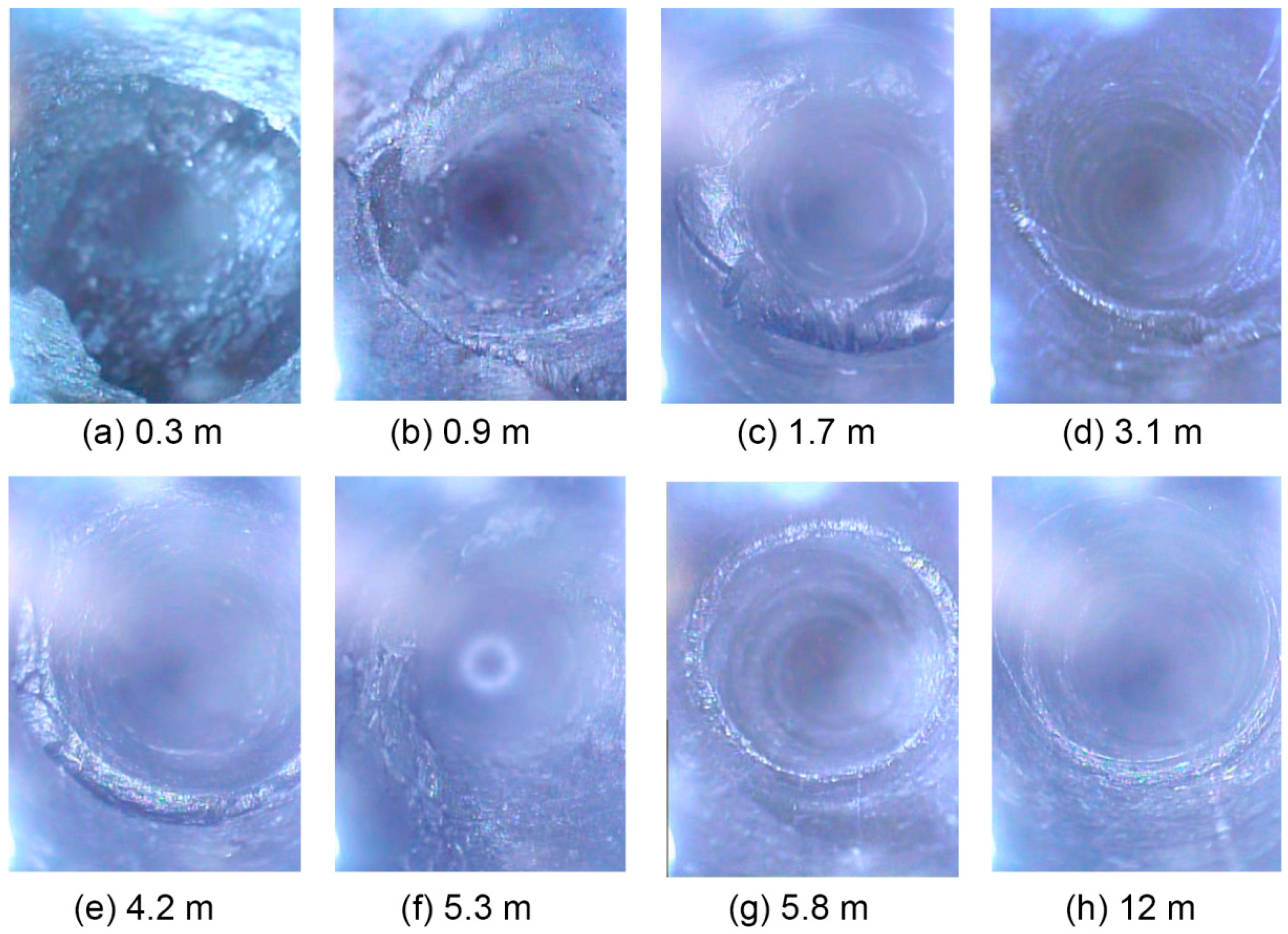
As seen in Table 1, under the combined effects of tectonic stresses of the syncline and dura-processes of water saturation and weathering surrounding rock of the -415 traveling roadway suffers from tremendous rock mass strength reduction, attributed to breaking and structure disintegration after several cases of repair. They are typical soft rocks, generally with low and poor qualities. The borehole optical televiewer imaging (Figure 5) shows that the shallow surrounding rock of the roadway is severely cracked and can hardly maintain its stability. Extensive development of cracks was found at the depth of 4.2 m (Figure 5e), tending to gradually fade away as the depth increased. Furthermore, owing to strong water absorption of muddy components such as kaolinite, water intruding via micro cracks led to non-uniform expansion of clay interstitial materials and, consequently, layer-curling fold structures occurred at certain depths (Figure 5f). What is more, the surrounding rock integrity showed no improvement until it reached deep areas (at the depth of about 12 m).
2.3. Large Deformation Failure of Weak Rock Tunnel
On the basis of the field survey and monitoring results of the -415 traveling roadway, the roadway deformation failure characteristics can be summarized in the following aspects:
- (1)
- Large, non-uniform, and long-term duration deformation. Under the combined effects of tectonic stresses and surrounding rock collapse, the implemented roadway repair based on the “bolt–cable–mesh” support system presents no control on surrounding rock, as water saturation and weathering processes continue affecting extensively fractured surrounding rock mass. This leads to further weakening, swelling, and disintegration. Particularly in the middle roadway (60–80 m), floor heave is considerably severe, which is also accompanied by roof subsidence and sidewall shrinkage (Figure 6a). The roadway surrounding rock mass, with blocky structures and developed joints, collapses and presents large and uneven deformation. Moreover, the repair construction ends up with no control over the deformation of the roadway surrounding rock. The cross-section shape of the -415 traveling roadway after four months of continuous deformation is displayed in Figure 6b, with the contraction ratio through the whole roadway as high as 30–50%.
- (2)
- Supporting material failure. After being repaired using the “bolt–cable–mesh” support system, the roadway still maintains relatively fast deformation. Some support materials are damaged within three months of installation. The supporting process of roadway surrounding rock can be seen as the coupling process of unloading adjustment of the surrounding rock and support-based control and constraint. The coupling failure of rigidity and strength between the two is the major contributor to the support system’s destruction. Rock cables and bolts are extensively pulled and break up at the locker (Figure 6a), which suggests that the support system design does not specifically consider the large deformation instability mechanisms of the roadway during repair construction, and the resultant support system can no longer suppress the instability of the roadway surrounding rock.
3. Numerical Model Establishment
3.1. UDEC Trigon Approach
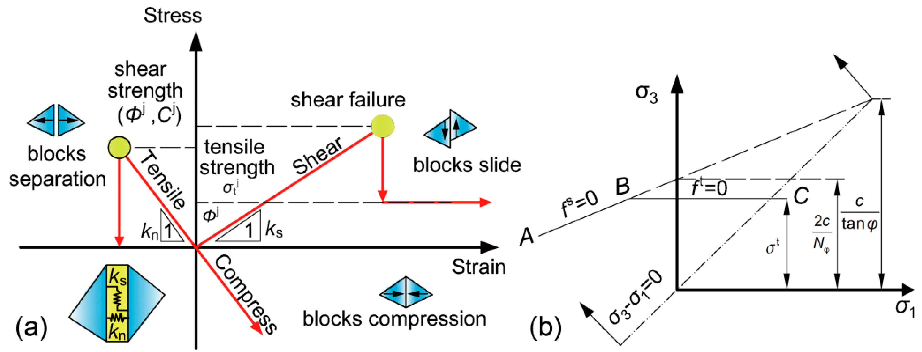
In this study, the UDEC trigon approach was adopted, due to its built-in advantages in simulating crack initiation, propagation, interaction, and coalescence [41], thus promoting applicability to the weathered and fractured roadway surrounding rock environment of this research. With the help of the custom-developed FISH function [2], this model cuts the Voronoi polygonal blocks into constituent trigon blocks. In the UDEC trigon model, rock is regarded as the aggregation of trigon blocks contacting and bonding with each other. Every trigon block is set as an elastic element, and, on the basis of stress states and characteristics of the contact surface, only shear or tensile failures along the interface can occur [42], which subsequently lead to instability and destruction of macroscopic rock mass. The constitutive model characterizing the structure (block) contact infinitesimal is illustrated in Figure 7a. In the proposed model, it is defined that a linear stress–displacement correlation exists along the normal direction of the contact surface between trigon blocks, and is dominated by the stiffness coefficient kn [43].
where is the incremental normal stress and is that of normal displacement.
In the case of the normal stress exceeding the tensile strength of the contact surface, tensile failure occurs, and the contacting structure is destroyed. At this time, the value of would be 0.
In this model, below the shear strength (), the shear mechanical behavior of the contact surface is dominated by the shear stiffness (), and the stress–displacement relationship can be expressed as follows:
if , then
if , then
where and are increments of elastic shear displacement and total shear displacement, respectively.
3.2. Deformable Block Model
Since the rock tensile strength is far lower than its compressive strength, the tensile failure between blocks is simulated using the Mohr–Coulomb elastoplastic constitutive model. The failure criterion is represented in Figure 7b. The failure envelope from points A to B is defined by the Mohr–Coulomb yield function [44].
The failure envelope from Points B to C is defined by the tension yield function [44].
where c, φ, and σt are the cohesion, internal friction angle, and tensile strength, respectively, and Nφ = (1 + sinφ)/(1 − sinφ).
3.3. Determination of Rock Mass Parameters
In this model, the bulk modulus (K) and shear modulus (G) of the blocks could be computed through the following formulas:
The cohesion (Cb), friction angle (φb), and tensile strength (σtb) of blocks were obtained from available previous studies [32,41,43,45].
The normal stiffness (kn) and shear stiffness (ks) of contacts were determined using the following formulas:
where Δzmin is the smallest width of the zone adjoining the contact in the normal direction.
The parameters of contact (i.e., cohesion Cj, friction angle φj, and tensile strength σtj) were obtained through a series of simulated compression tests based on trigon blocks [41]. Firstly, initial values were assigned to each micro-parameter, with respect to the material characteristics. Then, iterations of numerical simulation of uni-axial compression tests and simulation result evaluation were carried out and continued until the simulation results were consistent with the compressive strength (σcmass) and deformation modulus (Emass) of rock mass presented in Table 1 (Figure 8). The final parameters for the blocks and contacts for each type of rock in this model are listed in Table 2, and the final simulated results of the uni-axial compression tests are expressed in Figure 8.
3.4. Numerical Model and Simulation Scheme for the -415 Traveling Roadway
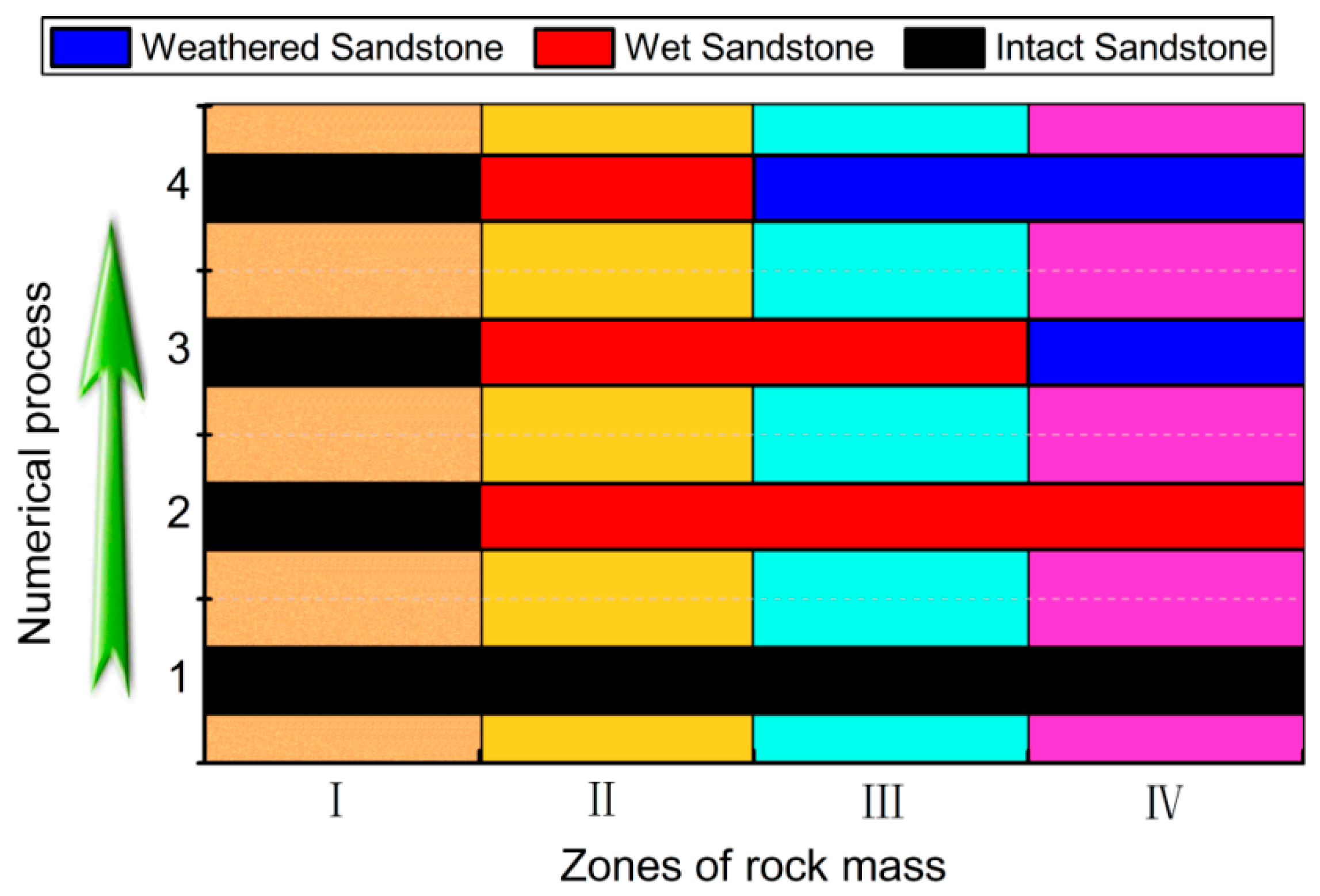
A numerical model for the -415 traveling roadway, based on the lithology of surrounding rock 140 m away from the roadway opening, was established in UDEC using trigon blocks. The numerical model was 60 m × 55 m, composed of 3712 blocks, with rock strata dip angles of 10°. To improve computation efficiency, small trigon blocks, with an average edge length of less than 0.3 m, were only generated in a 16 m × 17 m surrounding area with decisive effects on roadway stability. To better simulate the inclined rock strata, the remaining blocks were set as rectangles. Vertical and horizontal stresses were applied to the top and lateral boundaries of the model, respectively, to simulate the in situ stress environment. With reference to the field in situ testing, the vertical stress was 14.6 MPa, while the horizontal stress was 20.2 MPa. A displacement constraint was applied to the base boundary. The rock mass around roadway was divided into four regions, with an interval thickness of 2 m, as shown in Figure 9, and the state of rock mass within each region was described by assigning the corresponding mechanical parameters in Table 2. The assignment schemes shown in Figure 10 were conducted in a stepwise manner to simulate the failure mechanisms during the water saturation and weathering processes.
4. Failure Mechanisms of Surrounding Rock in Numerical Simulation
4.1. Displacement Analysis
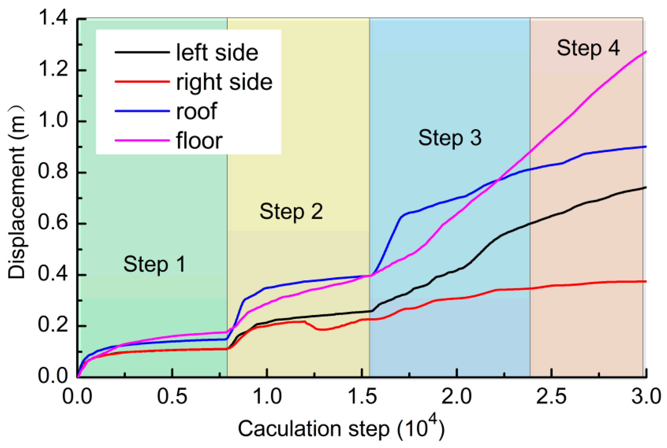
The displacement variation (convergence) of the roadway surrounding rock with the water saturation and weathering processes propagating along the depth is illustrated in Figure 11. As the degrees of water saturation and weathering effects in the roadway surrounding rock grew, the displacement variation was characterized by stepwise evolution. Owing to the relatively high horizontal stresses imposed by the syncline structure, uneven larger deformation occurred in the roadway. Roof and floor displacements apparently surpassed those of the two sides. The evolution of displacement vectors within the roadway surrounding rock is revealed in Figure 12; after excavation, the surrounding rock presented small converging deformation across the whole cross-section, while the deformation magnitudes of the roadway roof and two sides were smaller than that of the floor (Figure 12a), owing to reinforcement provided by the support system. As the surrounding rock mass suffered from continuous strength weakening due to water saturation and weathering processes, the deformation rates of the roof and two sides tended to reach their equilibrium. However, the floor was found with rapid heaving, because of its collapsed self-stabilizing ability. Moreover, asymmetric large deformation was observed in the roadway, with the left-side deformation higher than that of the right side, and the heave on the right floor was far less than that on the left floor. Failure first occurred in the roof and floor, which was consistent with the field observation. The simulation results indicate that the roadway failed to achieve equilibrium between surrounding rock unloading convergence and effective load-bearing of the support system. The deformation was sustained with increasing rates, and the current support system was unable to effectively control surrounding rock stability.
4.2. Stress Analysis
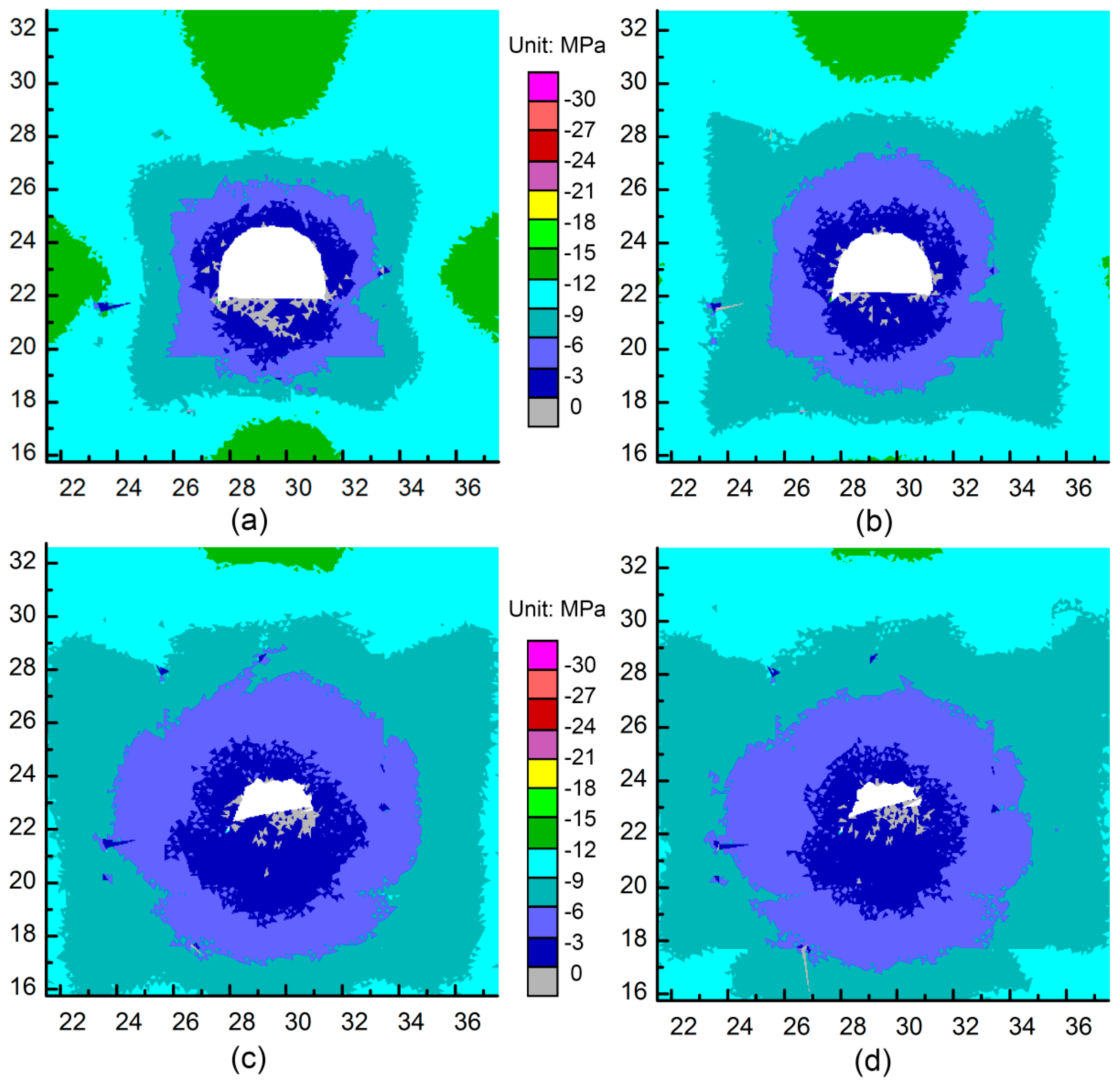
The principal stress evolutions of the roadway surrounding rock as water saturation and weathering processes propagated deeper are illustrated in Figure 13 and Figure 14. Owing to the large horizontal tectonic stresses induced by the syncline structure, a general stress distribution pattern of the roadway surrounding rock, featuring unloading at the two sides and stress concentration at the roof and floor, can be observed in Figure 13a, which complied with the field observation indicating damages at the roadway roof and floor. As the strength of the surrounding rock reduced, with water saturation and weathering processes penetrating from shallow into deep rock zones, the shallow surrounding rock first failed and reached the residual-strength stage, because of deviatoric stresses exceeding its compressive strength. The reduction in self-load-bearing capacity of the shallow surrounding rock transferred load onto rock in deeper areas with higher load-bearing capacity, which was embodied as the migration of stress concentration areas into deeper rock areas and the unloading status of shallow surrounding rock accompanied by tremendous displacement, swelling, and destruction, as can be seen in Figure 13b–d. The unloading degree of the floor was higher than that of the remaining parts, which implied severer damages at this position. Reinforcement and constraint provided by the support system helped the roof and two sides of the roadway avoid the mechanical tensile status of shallow surrounding rock and consequent failure. Unfortunately, a lack of support system for the floor led to a large tensile stress area, as shown in Figure 14. It should be noted that the tensile stress distribution coincided with the deformation failure area of the floor, and this was one of the major contributors to floor heave failure. It is clear that the support system can efficiently suppress tensile stress distribution in the shallow surrounding rock near the free roadway surface, and support should be constructed for the floor of the -415 traveling roadway.
4.3. Crack and Plastic Zone Analysis
Massive cracks occurred during the pressure release process of the roadway surrounding rock, and their initiations and propagations had critical effects on the rock strength and self-stabilizing capacity [46]. The crack evolution inside the surrounding rock of the -415 traveling roadway is shown in Figure 15. After the roadway was supported, shear cracks were mostly limited in the roof and floor, while tensile cracks were concentrated in the roadway floor. However, their development depth and degree were both limited, which can be seen in Figure 15a. This is attributed to the fact that the untied support surrounding rock system still had relatively good self-stabilizing ability, and stress concentration mainly occurred in the roadway roof and floor. Tensile cracks were more developed in the floor rock area than other parts, which was precisely ascribed to absent reinforcement and constraint provided by the support system and consequent incompetence with regard to suppress tensile stress (Figure 13a). Initiation and propagation of tensile cracks were controlled by local tensile stress values with respect to the rock mass tensile strength [47].
As water saturation and weathering processes proceeded, strength weakening of the surrounding rock was sustained. Correspondingly, the tensile crack in the floor was seen with a considerably growing distribution in range and density, and tended to propagate toward the two sides, while the tensile crack distribution range in the roof presented no obvious expansion. This suggests that the support system to some extent improved the stress status of the shallow surrounding rock in the roof, reduced tensile cracks, and effectively maintained the self-stabilizing capacity of surrounding rock. The floor with no support became a weak point in the whole section of the roadway, due to the incapability of suppressing tensile stresses and rock mass swelling and breakage. Meanwhile, destruction of the floor led to large deformation of the roadway sides. The shapes of plastic zones in different areas within the surrounding rock are illustrated in Figure 16. It can be seen that yielding failure was also mainly distributed within the roof and floor, with failure propagation in the floor much more obvious than in the roof and two sides.
In addition, the yielding failure distribution in the left side of the roadway was more concentrated than that in the right side, corresponding to the observed asymmetric deformation of the -415 traveling roadway. The aforementioned simulation results proved that the roadway maintenance support scheme cannot effectively suppress large deformation and instability failure of the roadway surrounding rock.
4.4. Failure Mechanism Analysis
The failure mechanism of the -415 traveling roadway penetrating through a syncline structure under the maintenance support scheme can be summarized as follows:
- Contradiction between the complex in situ stress field and poor surrounding rock properties. The in situ stress field is a dominant factor characterizing the occurrence environment of the roadway, and the value, direction, and spatial distribution greatly impact the mechanical properties of the surrounding rock, the deformation failure of the support system and, ultimately, the stability of the roadway support engineering [48]. As the -415 traveling roadway obliquely penetrates through a syncline structure, the measured principal stress direction deflects from the roadway axis with certain angles, rather than coinciding with it, while the roadway is affected by many associated small faults. Hence, the in situ stress environment around the roadway is extremely complex, and such high and complex stress is a major challenge for the roadway support. Furthermore, the roadway surrounding integrity is compromised by the geological structures, which is embodied in the macroscopic scale as extensive development of cracks and greatly deteriorated rock mass mechanical properties. Moreover, the presence of muddy components such as kaolinite makes these cracks conduits for air and water intrusion, which leads to sustained weathering processes from shallow to deep. This further degrades the mechanical properties and self-stabilizing capacity of the surrounding rock. Once deviatoric stresses, formed by the free space of the roadway, exceed the shallow surrounding rock strength, plastic failure of rock mass and subsequent unloading occur [49], accompanied by massive associated cracks. This cyclic process integrating water saturation and weathering impacts, strength weakening, plastic failure, stress unloading, crack development, and then weathering of deeper surrounding rock continuously proceeds, and the failure zone correspondingly shifts from the shallow surrounding rock into deep areas. Under such circumstances, a contraction between the highly complex in situ stress field and the sustained property deterioration of surrounding rock comes into being.
- Misalignment between incomplete support and surrounding rock property deterioration. It is clear that the poor surrounding rock properties and their constant degrading were some of the major contributors to roadway destruction. The adopted roadway repair support system simply based on the general roadway support experience incorporates no specific measures to manage surrounding rock water saturation and weathering processes (i.e., shotcrete, etc.) and, therefore, can maintain roadway stability only shortly after support construction. Such misalignment between the incomplete support and sustained surrounding rock deterioration (driven by water saturation and weathering processes) results in an incapability of solving key problems that give rise roadway destruction and failure of the roadway support.
- No support for the roadway floor. The surrounding rock deterioration covers the whole roadway cross-section, which means that the floor rock mass has equal degrading potential compared to the rock mass at other positions. It should be noted that the roadway roof and floor maintain high stress concentration, from a mechanical point of view, which makes them vulnerable to surrounding rock control and prone to plastic instability. The support system to some extent improves the mechanical status and plastic failure proneness of the surrounding rock of the roadway roof and two sides. However, as property deterioration proceeds and shifts from shallow to deep, the importance of such improvements is highlighted by the outcome of a lack of floor support. The destruction of the surrounding rock at the roadway floor and the unfavorable stress status stimulate the loss of self-stabilizing capacity, and the floor heave deformation compromises the mechanical basis of the roadway side stability, leading to the destruction and instability of the two sides of the roadway from base to top.
5. The Combined Support Approach of “Bolt–Cable–Mesh–Shotcrete + Grouting”
5.1. Control Strategies
From the above analysis, it can be concluded that large and complex in situ stresses, sustained surrounding rock property deterioration, and the incomplete support system are the major contributors to the instability and destruction of the -415 traveling roadway. Given that the roof and floor are key areas in terms of roadway deformation and damage, the following roadway surrounding rock control strategy is proposed:
- Strengthening reinforcement and homogenization of surrounding rock. Tectonic and weathering processes compromise microscopic structures of the surrounding rock, while cracking, swelling, and crushing reduce its cohesion and strength. Therefore, the roadway surrounding rock generally presents mechanical characteristics of soft rock. Moreover, the uncertainty of joint growth in the inclined formation and the layered parallel distribution of discontinuities result in the macroscopic asymmetry deformation of the roadway. These sustained weakening processes eliminated the engineering basis for the active support mechanism of bolts, and failure to achieve equilibrium between the surrounding rock–bolt support structure and external pressure. Previous studies showed that, in the case of fully fractured surrounding rock, grouting is an effective approach to achieve homogenization and rigidity enhancement [50], able to improve the residual strength by 70–200%, which is also clear in Figure 8. Grouting can replace the role of muddy interstitial materials that become unconsolidated and debonded, while re-cementing the matrix and developing stable microscopic structures. In such cases, the surrounding rock mechanical properties are enhanced, and the self-stabilizing capacity is improved.
- Closing weathering passage. The uncontrollable weathering process of surrounding sandstones is one of the drivers for surrounding rock deterioration, and pre-existing cracks inside surrounding rock serve as passages for air and water intrusion. Grouting can not only strengthen surrounding rock, but also plug passages provided by cracks, effectively protecting deep sandstone from weathering damage. In addition, shotcrete over the full roadway surface can form a rigid protection layer to seal the surrounding rock and achieve a better protection performance.
- Coupling support composed of the support system and surrounding rock. The current incomplete roadway support incorporates no consideration for coupling with mechanical status evolution and vulnerable regions of the -415 traveling roadway surrounding rock, thus resulting in roadway instability. Given the premise of the fracturing and unloading status of roadway surrounding rock, this paper comprehensively takes into consideration the grouting reinforcement and flexible active support mechanism, which are essentially implemented using the high-strength pre-stressed bolt support and the rigid support mechanism of shotcrete. The effective support system should consider these aforementioned construction efforts, and incorporate both rigidity and flexibility, so as to control the roadway surrounding rock.
5.2. The Combined Support Approach
According to these control strategies, the “bolt–cable–mesh–shotcrete + grouting” combined support approach is proposed. Here, we provide a more detailed description of the approach; the combined support consists of the reinforcement arch formed by grouting within surrounding rock, and the flexible support is provided by pre-stressed bolts and cables and a rigid support based on the concrete shell (composed of the roof shotcrete and floor concrete). The roadway is first expanded into a 4.0 m × 3.4 m semicircle arch cross-section (with the diameter of the top round arch equal to 4.0 m), supported by bolts and cables. Then, surrounding rock grouting is implemented, following by supplement of the pre-stressing force of bolts and cables. The last component of the combined support system is the concrete shell covering the whole roadway surface to provide rigid reinforcement and surrounding rock isolation. The final support program is presented in Figure 17.
- Coupling support of pre-stressed bolts ad cables. High-strength Φ22 mm × 2000 mm bolts and Φ17.8 mm × 6300 mm pre-stressed cables are used, with row and column spacing of 700 mm × 700 mm and 1400 mm × 1400 mm, respectively. The high-density cables in the roof are mainly for the purpose of reinforcing roof rock mass prone to destruction. Bolts and cables are installed together with a steel mesh with a grid size of 100 mm × 100 mm. Then, a preliminary concrete layer with thickness of 50 mm is sprayed to preliminarily seal surrounding rock and suppress outward flow of grout. Bolts and cables are not pre-stressed when they are installed. After completion of grouting, pre-stresses of 60 kN and 120 kN are then applied to bolts and cables, respectively, to activate the active flexible support function of pre-stressed bolts.
- Surrounding rock grouting. Eight anchorage–grouting integrated high-strength grouting bolts of Φ22 mm × 2800 mm are installed in the roadway roof and two sides at the positions of original conventional bolts, as shown in Figure 17 (with row and column spacing of 1400 mm × 1400 mm). Such grouting bolts have tensile strengths of up to 600 MPa and can be installed using the same installation technique as conventional bolts, greatly improving the support strength and installation velocity. Six full-threaded grouting bolts of Φ22 mm × 1800 mm are installed in the floor, with row and column spacing of 700 mm × 1400 mm. The slurry of cement and water glass is selected as the grout material, with water cement ratios of 0.8/1–1/1 and slurry/water glass ratios equal to 1/0.03–1/0.05. The used cement is the conventional Portland Cement 425, the water glass modulus is 3, and the Baume degree is 40°. Since bolt support and preliminary shotcrete are constructed to constrain the radial displacement of surrounding rock prior to grouting, the grouting pressure is set as 6 MPa. The grouting completion criterion is that the single hole is filled with grout at the operating pressure and no more grout can be injected.
- High-strength shotcrete shell. Upon completion of grouting, the roadway roof is again sprayed with concrete to achieve a total layer thickness of 200 mm. The shotcrete strength is C20. An 816-mm double-layer steel reinforcement cage with spacing of 150 mm and grid size of 200 mm × 200 mm is installed on the roadway floor, onto which 300-mm-thick concrete is then poured. Thus, the rigid concrete support covering the full roadway surface is developed, which couples the surrounding rock grouting reinforcement and flexible pre-stressed support system into an integrated composite support system.
5.3. Numerical Validation of the “Bolt–Cable–Mesh–Shotcrete + Grouting” Combined Support Approach
The effectiveness of the proposed new combined support approach was validated using numerical simulation. The grouting depth was set between 2 m and 3.8 m. In other words, the correction program of step 4 in Figure 10 was adopted, and zone IV was defined as the grouting area in the simulation model. Mechanical properties of “grouting sandstone” in Table 2 were adopted, which were based on the results of uni-axial compression tests of grouting sandstone specimens. Mechanical parameters of support materials in the simulation are listed in Table 4 and Table 5.
The principal stress distribution within surrounding rock under the new combined support system is shown in Figure 18. Compared with that in the original support scheme, it shows that the stress disturbance area and unloading depth of the roadway surrounding rock were both greatly reduced, particularly in the roadway floor and two sides. The stress concentration areas in the roof and floor were also mainly limited in the areas covered by the active support of bolts and grouting (Figure 18a). Meanwhile, the tensile stress distribution in the shallow surrounding rock was effectively suppressed, as shown in Figure 18b, which indicates that the new combined support system provided sufficient support resistance, improved the stress status of the surrounding rock, and avoided tensile failure of shallow rock and yield failure of deep rock.
As is shown in Figure 19, only minor tensile failure occurred in the roadway floor, and a small amount of yielding failure remained at the surrounding rock area weakened by water saturation and weathering processes outside the active support area. Compared with the case of the original support scheme, the mechanical states of the roadway surrounding rock were greatly enhanced. The convergence deformation of the roadway surrounding rock became more uniform, and synchronous load-bearing and deformation of the two sides were basically achieved, with the help of reinforcement and homogenization implemented by surrounding rock grouting. Moreover, the displacement of the roadway surrounding rock considerably declined to only 10–20% of that in the case of the original support approach. These results suggest that the new combined support approach was able to coordinate the roadway surrounding rock and support system, and effectively suppress the uneven large deformation.
5.4. Application to the -415 Traveling Roadway
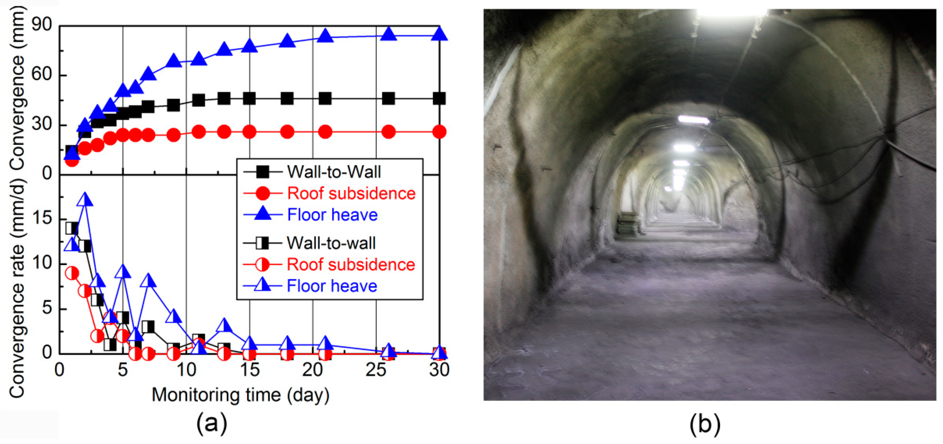
After expanding the severely deformed -415 traveling roadway to the standard dimension, support was implemented using the improved support system. The effectiveness of the new combined support system proposed in this paper was validated using the surface convergence (displacement) monitoring data collected during maintenance. The monitoring station placement is illustrated in Figure 1b, and the observed roadway surrounding rock displacement convergence is presented in Figure 20a. Under the combined effects of fracturing and full unloading of deep rock, rock mass weathering suppression, and enhanced rigidity of active support, the roadway presented a limited overall deformation. Upon completion of the support construction, the roadway entered the coordinating adjustment process between the surrounding rock and support system, during which certain deformation of the support structure is acceptable to allow for the balance between the generated support resistance and surrounding rock pressure. This process was embodied in the macroscopic scale as the roadway displacement grew at a relatively high rate (up to 17 mm/day) and then slowed down and finally reached its equilibrium. The process lasted for about 26 days. At last, the floor heave, roof subsidence, and side shrinkage of the roadway were 80 mm, 50 mm, and 30 mm, respectively, with a displacement ratio of 4.8%. As is shown in Figure 20b, the roadway maintained a relatively intact shape. It is demonstrated that the new support system performed well in terms of roadway supporting, and successively controlled surrounding rock of the -415 traveling roadway, which is a water-dripping soft rock roadway located in the tectonic stress area.
6. Conclusions
This paper introduced a case study on failure mechanisms and corresponding support approaches of a soft rock roadway subjected to water saturation and large complex tectonic stresses. The field observation indicated that the shallow surrounding rock of the roadway was severely weathered and extremely prone to crushing, with inferior load-bearing capacity. The GSI method was adopted to calibrate rock mass properties, with respect to the surrounding rock damaged status and experimental strength measurements. These parameters helped restore and reveal mechanical behaviors of rock mass in simulation.
A simulation model based on the surrounding rock lithology was established in UDEC using trigon blocks. By calibrating mechanical properties of roadway surrounding rock zone by zone in a stepwise manner, the instability and failure mechanisms of the roadway during water saturation and weathering processes were investigated.
Comprehensively considering field observations and simulation results, this paper shed light on the mechanisms behind large deformation instability of the soft rock roadway penetrating a geological structure. Stresses were concentrated in the roadway roof and floor, due to the large horizontal tectonic stress. As water saturation and weathering processes shifted toward the deeper rock area, the shallow surrounding rock in the roof and floor cracked and collapsed. Unloading was triggered by loss of self-load-bearing capacity, which was accompanied by tremendous displacement, swelling, and destruction. The incomplete support could not efficiently restrain surrounding rock, and the extensive presence of tensile stresses stimulated crack development in the floor, leading to severer destruction. Moreover, the original support system was incapable of suppressing surrounding rock weathering and, thus, the sustained mechanical property deterioration, let alone provide sufficient support resistance to maintain the equilibrium between the support system and surrounding rock. In the macroscopic scale, the roadway was found with roof cracking and subsidence, severe floor heave, and asymmetric large deformation.
A combined support system of “bolt–cable–mesh–shotcrete + grouting” was proposed to achieve alignment among the surrounding rock reinforcement, flexible active support of high-strength pre-stressed bolts, and rigid support shotcrete. The supporting performance was investigated through both numerical simulation and field testing. Results demonstrated that the proposed combined support system is highly applicable to the type of soft rock roadway in question, and the surrounding rock stability was effectively controlled. Findings of this research can provide valuable references for instability mechanisms and control techniques for soft rock roadways of the same type.
Author Contributions
Project administration and funding acquisition, X.F. and G.X.; methodology, X.F.; laboratory experiments and numerical simulation, G.X. and C.G.; data curation, C.G.; field testing, T.W.; writing—original draft preparation, G.X.; writing—review and editing, T.W.
Funding
This research was funded by the State Key Laboratory of Coal Resources and Safe Mining, CUMT, grant number SKLCRSM16X01, and the Postgraduate Research and Practice Innovation Program of Jiangsu Province, grant number KYLX_1405.
Acknowledgments
The authors would like to express our appreciation for the valuable comments made by two anonymous reviewers and the editor, which helped us to improve the quality of this paper.
Conflicts of Interest
The authors declare no conflicts of interest.
References
- National Bureau of Statistics of the People’s Republic of China. Statistical Bulletin on National Economic and Social Development in 2018; National Bureau of Statistics of the People’s Republic of China: Beijing, China, 2018.
- Yang, S.Q.; Chen, M.; Jing, H.W.; Chen, K.F.; Meng, B. A case study on large deformation failure mechanism of deep soft rock roadway in Xin’an coal mine, China. Eng. Geol. 2017, 217, 89–101. [Google Scholar] [CrossRef]
- Ma, C.Q.; Wang, P.; Jiang, L.S.; Wang, C.S. Deformation and control countermeasure of surrounding rocks for water-dripping roadway below a contiguous seam goaf. Processes 2018, 6, 77. [Google Scholar] [CrossRef]
- Vasarhelyi, B. Statistical analysis of the influence of water content on the strength of the miocene limestone. Rock Mech. Rock Eng. 2005, 38, 69–76. [Google Scholar] [CrossRef]
- Afrouz, A.; Harvey, J.M. Rheology of rocks within the soft to medium strength range. Int. J. Rock Mech. Min. Sci. Geomech. Abstr. 1974, 11, 281–290. [Google Scholar] [CrossRef]
- Van Eeckhout, E.M. The mechanisms of strength reduction due to moisture in coal mine shales. Int. J. Rock Mech. Min. Sci. Geomech. Abstr. 1976, 13, 61–67. [Google Scholar] [CrossRef]
- Dunning, J.; Douglas, B.; Miller, M.; McDonald, S. The role of the chemical environment in frictional deformation: Stress corrosion cracking and comminution. Pure Appl. Geophys. 1994, 143, 151–178. [Google Scholar] [CrossRef]
- Chugh, Y.P.; Missavage, R.A. Effects of moisture on strata control in coal mines. Eng. Geol. 1981, 17, 241–255. [Google Scholar] [CrossRef]
- Li, Q.H.; Shi, W.P.; Yang, R.S. Deformation mechanisms in a coal mine roadway in extremely swelling soft rock. SpringerPlus 2016, 5, 1310. [Google Scholar] [CrossRef]
- Sun, X.M.; Chen, F.; Miao, C.Y.; Song, P.; Li, G.; Zhao, C.W.; Xia, X. Physical modeling of deformation failure mechanism of surrounding rocks for the deep-buried tunnel in soft rock strata during the excavation. Tunn. Undergr. Space Technol. 2018, 74, 247–261. [Google Scholar] [CrossRef]
- Yuan, Y.; Wang, W.J.; Li, S.Q.; Zhu, Y.J. Failure mechanism for surrounding rock of deep circular roadway in coal mine based on mining-induced plastic zone. Adv. Civ. Eng. 2018, 2018, 1835381. [Google Scholar] [CrossRef]
- Tao, Z.G.; Zhu, C.; Zheng, X.H.; Wang, D.S.; Liu, Y.P.; He, M.C.; Wang, Y.B. Failure mechanisms of soft rock roadways in steeply inclined layered rock formations. Geomat. Nat. Hazards Risk 2018, 9, 1186–1206. [Google Scholar] [CrossRef] [Green Version]
- Nikolic, M.; Karavelic, E.; Ibrahimbegovic, A.; Miscevic, P. Lattice element models and their peculiarities. Arch. Comput. Methods Eng. 2018, 25, 753–784. [Google Scholar] [CrossRef]
- Boon, C.W.; Houlsby, G.T.; Utili, S. Designing tunnel support in jointed rock masses via the DEM. Rock Mech. Rock Eng. 2015, 48, 603–632. [Google Scholar] [CrossRef]
- Nikolic, M.; Ibrahimbegovic, A. Rock mechanics model capable of representing initial heterogeneities and full set of 3D failure mechanisms. Comput. Meth. Appl. Mech. Eng. 2015, 290, 209–227. [Google Scholar] [CrossRef]
- Ergenzinger, C.; Seifried, R.; Eberhard, P. A discrete element model to describe failure of strong rock in uniaxial compression. Granul. Matter 2011, 13, 341–364. [Google Scholar] [CrossRef]
- Nikolic, M.; Ibrahimbegovic, A.; Miscevic, P. Discrete element model for the analysis of fluid-saturated fractured poro-plastic medium based on sharp crack representation with embedded strong discontinuities. Comput. Meth. Appl. Mech. Eng. 2016, 298, 407–427. [Google Scholar] [CrossRef]
- Zheng, W.X.; Zhao, Y.L.; Bu, Q.W. The coupled control of floor heave based on a composite structure consisting of bolts and concrete antiarches. Math. Probl. Eng. 2018, 2018, 3545423. [Google Scholar] [CrossRef]
- Yu, W.J.; Liu, F.F. Stability of close chambers surrounding rock in deep and comprehensive control technology. Adv. Civ. Eng. 2018, 2018, 6275941. [Google Scholar] [CrossRef]
- Zhang, W.; He, Z.M.; Zhang, D.S.; Qi, D.H.; Zhang, W.S. Surrounding rock deformation control of asymmetrical roadway in deep three-soft coal seam: A case study. J. Geophys. Eng. 2018, 15, 1917–1928. [Google Scholar] [CrossRef]
- Kang, H.P.; Lin, J.; Fan, M.J. Investigation on support pattern of a coal mine roadway within soft rocks—A case study. Int. J. Coal Geol. 2015, 140, 31–40. [Google Scholar] [CrossRef]
- He, M.C.; Gong, W.L.; Wang, J.; Qi, P.; Tao, Z.G.; Du, S.; Peng, Y.Y. Development of a novel energy-absorbing bolt with extraordinarily large elongation and constant resistance. Int. J. Rock Mech. Min. Sci. 2014, 67, 29–42. [Google Scholar] [CrossRef]
- Chen, S.; Wu, A.; Wang, Y.; Chen, X.; Yan, R.; Ma, H. Study on repair control technology of soft surrounding rock roadway and its application. Eng. Fail. Anal. 2018, 92, 443–455. [Google Scholar] [CrossRef]
- Salimian, M.H.; Baghbanan, A.; Hashemolhosseini, H.; Dehghanipoodeh, M.; Norouzi, S. Effect of grouting on shear behavior of rock joint. Int. J. Rock Mech. Min. Sci. 2017, 98, 159–166. [Google Scholar] [CrossRef]
- Li, Q.H.; Yang, R.S.; Li, J.K.; Wang, H.; Wen, Z.J. Strength and cost analysis of new steel sets as roadway support project in coal mines. Adv. Mater. Sci. Eng. 2018, 2018, 3927843. [Google Scholar] [CrossRef]
- Yang, R.S.; Li, Q.H.; Li, Q.; Zhu, X.L. Assessment of bearing capacity and stiffness in new steel sets used for roadway support in coal mines. Energies 2017, 10, 16. [Google Scholar] [CrossRef]
- Wang, H.; Zheng, P.Q.; Zhao, W.J.; Tian, H.M. Application of a combined supporting technology with U-shaped steel support and anchor-grouting to surrounding soft rock reinforcement in roadway. J. Cent. South Univ. 2018, 25, 1240–1250. [Google Scholar] [CrossRef]
- Wu, A.X.; Chen, S.M.; Wang, Y.M.; Chen, X. Failure mechanism and supporting measures for large deformation of soft rock roadway in Baluba copper mine. Arch. Min. Sci. 2018, 63, 449–464. [Google Scholar]
- Sun, X.; Wang, L.; Lu, Y.; Jiang, B.; Li, Z.; Zhang, J. A yielding bolt-grouting support design for a soft-rock roadway under high stress: A case study of the Yuandian No. 2 coal mine in china. J. S. Afr. Inst. Min. Met. 2018, 118, 71–82. [Google Scholar] [CrossRef]
- Wang, Q.; Jiang, B.; Pan, R.; Li, S.C.; He, M.C.; Sun, H.B.; Qin, Q.; Yu, H.C.; Luan, Y.C. Failure mechanism of surrounding rock with high stress and confined concrete support system. Int. J. Rock Mech. Min. Sci. 2018, 102, 89–100. [Google Scholar] [CrossRef]
- Fairhurst, C.E.; Hudson, J.A. Draft ISRM suggested method for the complete stress-strain curve for intact rock in uniaxial compression. Int. J. Rock Mech. Min. Sci. 1999, 36, 279–286. [Google Scholar]
- Yao, Q.L.; Li, X.H.; Zhou, J.; Ju, M.H.; Chong, Z.H.; Zhao, B. Experimental study of strength characteristics of coal specimens after water intrusion. Arab. J. Geosci. 2015, 8, 6779–6789. [Google Scholar] [CrossRef]
- Fang, X.Q.; Xue, G.Z.; Liang, M.F.; Wang, G.; Fan, H.L. Micro-failure mechanism and bolt-grouting reinforcement support technology of water-bearing sandstone roadway. J. China Univ. Min. Technol. 2014, 43, 561–568. [Google Scholar]
- Yang, X.J.; Wang, E.Y.; Wang, Y.J.; Gao, Y.B.; Wang, P. A study of the large deformation mechanism and control techniques for deep soft rock roadways. Sustainability 2018, 10, 1100. [Google Scholar] [CrossRef]
- Gurocak, Z. Analyses of stability and support design for a diversion tunnel at the Kapikaya dam site, Turkey. Bull. Eng. Geol. Environ. 2011, 70, 41–52. [Google Scholar] [CrossRef]
- Sonmez, H.; Gokceoglu, C.; Ulusay, R. Indirect determination of the modulus of deformation of rock masses based on the GSI system. Int. J. Rock Mech. Min. Sci. 2004, 41, 849–857. [Google Scholar] [CrossRef]
- Ajalloeian, R.; Mohammadi, M. Estimation of limestone rock mass deformation modulus using empirical equations. Bull. Eng. Geol. Environ. 2013, 73, 541–550. [Google Scholar] [CrossRef]
- Hoek, E.; Marinos, P.; Benissi, M. Applicability of the geological strength index (GSI) classification for very weak and sheared rock masses. The case of the Athens Schist Formation. Bull. Eng. Geol. Environ. 1998, 57, 151–160. [Google Scholar] [CrossRef]
- Hoek, E.; Carranza-Torres, C.; Corkum, B. Hoek–Brown failure criterion–2002 edition. In Proceedings of the Fifth North American Rock Mechanics Symposium, Toronto, ON, Canada, 2002; pp. 267–273. [Google Scholar]
- Sonmez, H.; Ulusay, R. A discussion on the Hoek-Brown failure criterion and suggested modifications to the criterion verified by slope stability case studies. Bull. Earth Sci. Appl. Res. Cent. Hacet. Univ. 2002, 26, 77–99. [Google Scholar]
- Gao, F.Q.; Stead, D. The application of a modified Voronoi logic to brittle fracture modelling at the laboratory and field scale. Int. J. Rock Mech. Min. Sci. 2014, 68, 1–14. [Google Scholar] [CrossRef]
- Gao, F.Q.; Stead, D.; Coggan, J. Evaluation of coal longwall caving characteristics using an innovative UDEC trigon approach. Comput. Geotech. 2014, 55, 448–460. [Google Scholar] [CrossRef]
- Gao, F.Q.; Stead, D.; Kang, H.P. Simulation of roof shear failure in coal mine roadways using an innovative UDEC trigon approach. Comput. Geotech. 2014, 61, 33–41. [Google Scholar] [CrossRef]
- Itasca Consulting Group, Inc. Udec User Man; Itasca Consulting Group, Inc.: Minneapolis, MN, USA, 2008. [Google Scholar]
- Yang, S.Q.; Jing, H.W.; Wang, S.Y. Experimental investigation on the strength, deformability, failure behavior and acoustic emission locations of red sandstone under triaxial compression. Rock Mech. Rock Eng. 2012, 45, 583–606. [Google Scholar] [CrossRef]
- Yang, S.Q. An experimental study on fracture coalescence characteristics of brittle sandstone specimens combined various flaws. Geomech. Eng. 2015, 8, 541–557. [Google Scholar] [CrossRef]
- Diederichs, M.S.; Kaiser, P.K.; Eberhardt, E. Damage initiation and propagation in hard rock during tunnelling and the influence of near-face stress rotation. Int. J. Rock Mech. Min. Sci. 2004, 41, 785–812. [Google Scholar] [CrossRef]
- He, M.C.; Wang, X.Y.; Liu, W.T.; Yang, S.B. Numerical simulation on asymmetric deformation of deep soft rock roadway in Kongzhuang coal mine. Chin. J. Rock Mech. Eng. 2008, 27, 673–678. [Google Scholar]
- Shen, W.L.; Wang, X.Y.; Bai, J.B.; Li, W.F.; Yu, Y. Rock stress around noncircular tunnel: A new simple mathematical method. Adv. Appl. Math. Mech. 2017, 9, 1330–1346. [Google Scholar] [CrossRef]
- Narayaman, R.; Palanjing, A. Factors influencing the strength of steel fiber reinforced concrete. Dev. Fiber Reinf. Cem. Concr. 1986, 2, 1–8. [Google Scholar]
Figure 1.
(a) Location of the Wangzhuang coal mine, China; (b) plan of the investigated roadway.
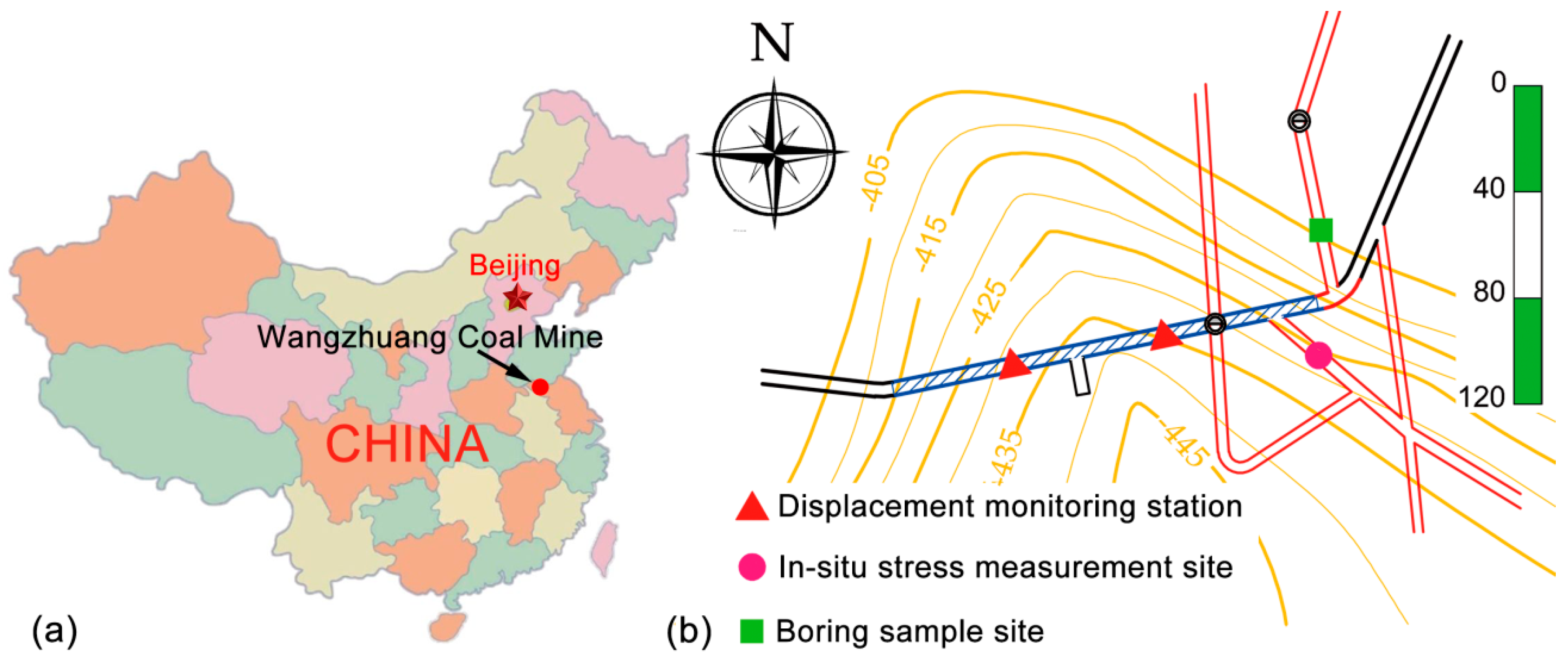
Figure 2.
Stratigraphic column and geological description nearby the study site.
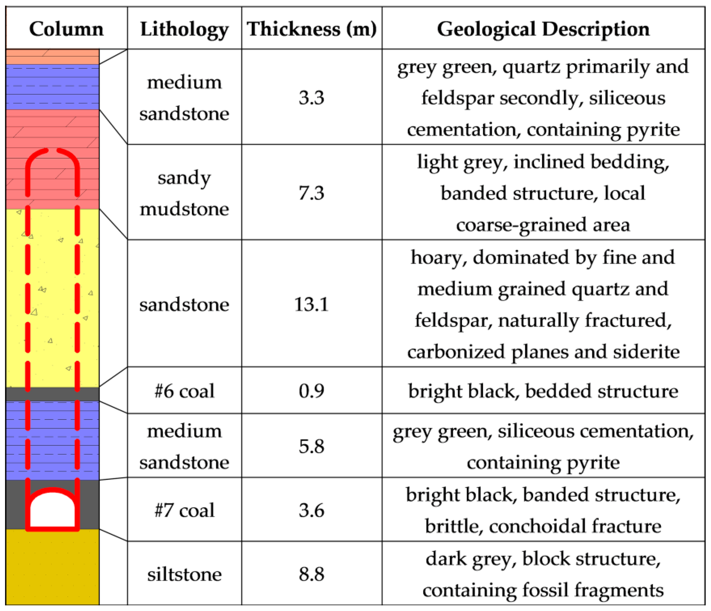
Figure 3.
X-ray diffraction spectrum of sandstone specimens.
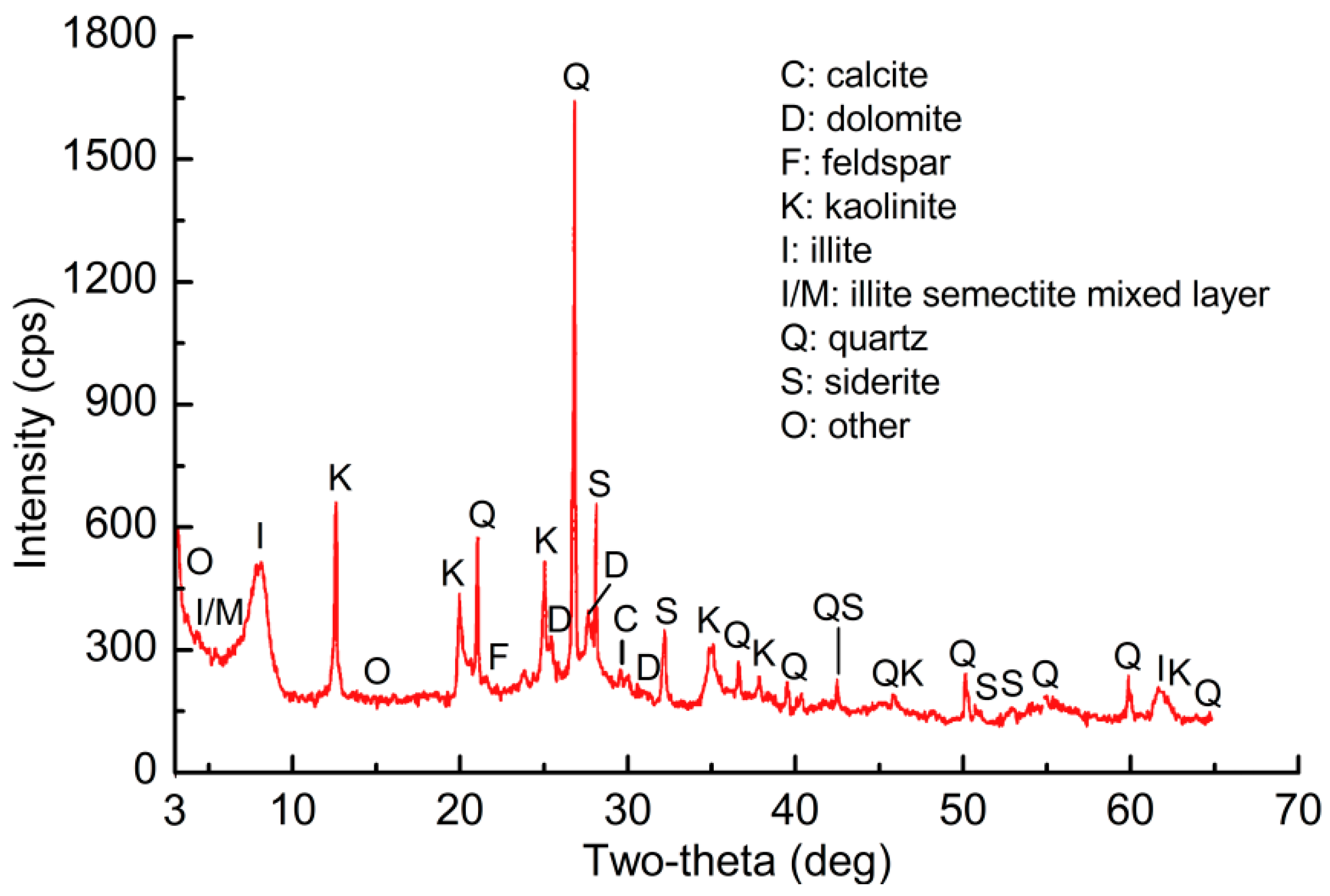
Figure 4.
Scanning electron microscope photos of sandstone specimens: (a) intact sandstone; (b) water-saturated sandstone; (c) weathered sandstone.
Figure 4.
Scanning electron microscope photos of sandstone specimens: (a) intact sandstone; (b) water-saturated sandstone; (c) weathered sandstone.
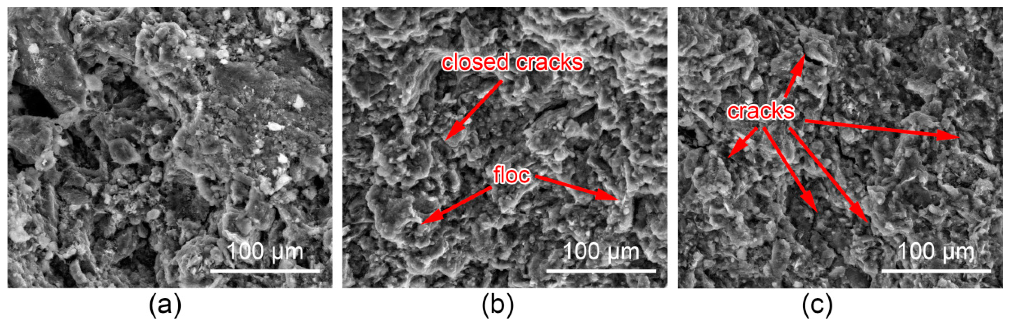
Figure 5.
Borehole optical televiewer imaging of surrounding rock at various depths.

Figure 6.
Failure modes in the -415 traveling roadway: (a) roof subsidence and sidewall shrinking; (b) sketch of the roadway’s cross-section 60 m away from the opening.
Figure 6.
Failure modes in the -415 traveling roadway: (a) roof subsidence and sidewall shrinking; (b) sketch of the roadway’s cross-section 60 m away from the opening.

Figure 7.
(a) Constitutive behavior of contact infinitesimals in this model; (b) Mohr–Coulomb failure criterion for blocks.
Figure 7.
(a) Constitutive behavior of contact infinitesimals in this model; (b) Mohr–Coulomb failure criterion for blocks.

Figure 8.
Stress–strain curves of simulated uniaxial compression tests for rock mass.

Figure 9.
Numerical model for the -415 traveling roadway.
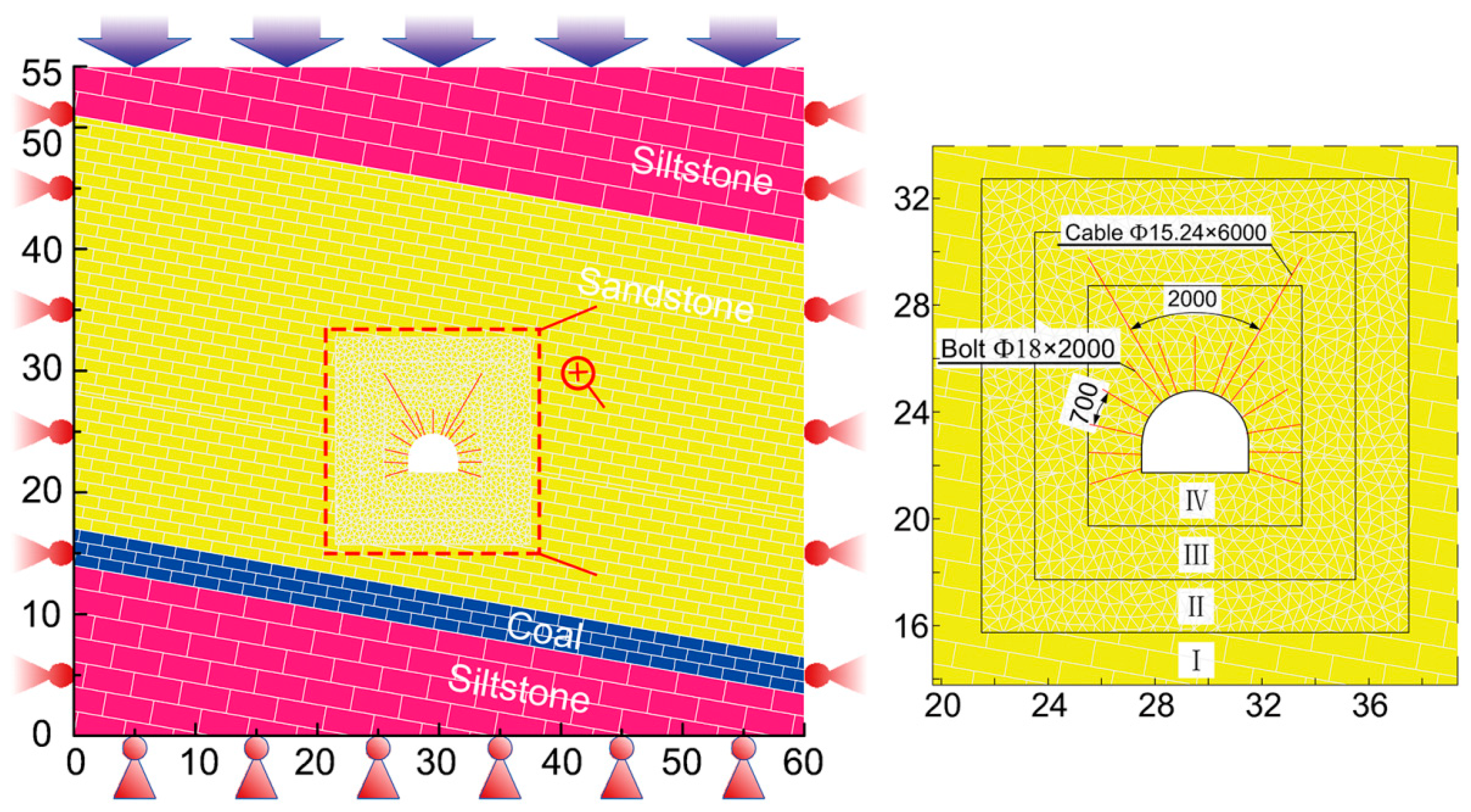
Figure 10.
Simulation scheme for the -415 traveling roadway.

Figure 11.
Deformation curves of surrounding rock, measured at the roadway surface.

Figure 12.
Numerical displacement vector mapping of the roadway surrounding rock during different simulation processes: (a) simulation step 1; (b) simulation step 2; (c) simulation step 3; (d) simulation step 4.
Figure 12.
Numerical displacement vector mapping of the roadway surrounding rock during different simulation processes: (a) simulation step 1; (b) simulation step 2; (c) simulation step 3; (d) simulation step 4.

Figure 13.
Simulation maximum principal stress distributed within the surrounding rock during different simulation processes: (a) simulation step 1; (b) simulation step 2; (c) simulation step 3; (d) simulation step 4.
Figure 13.
Simulation maximum principal stress distributed within the surrounding rock during different simulation processes: (a) simulation step 1; (b) simulation step 2; (c) simulation step 3; (d) simulation step 4.

Figure 14.
Simulation minimum principal stress distributed within the surrounding rock during different simulation processes: (a) simulation step 1; (b) simulation step 2; (c) simulation step 3; (d) simulation step 4.
Figure 14.
Simulation minimum principal stress distributed within the surrounding rock during different simulation processes: (a) simulation step 1; (b) simulation step 2; (c) simulation step 3; (d) simulation step 4.

Figure 15.
Crack propagation within surrounding rock during different simulation processes: (a) simulation step 1; (b) simulation step 2; (c) simulation step 3; (d) simulation step 4. Shear and tensile cracks are colored in red and green, respectively.
Figure 15.
Crack propagation within surrounding rock during different simulation processes: (a) simulation step 1; (b) simulation step 2; (c) simulation step 3; (d) simulation step 4. Shear and tensile cracks are colored in red and green, respectively.
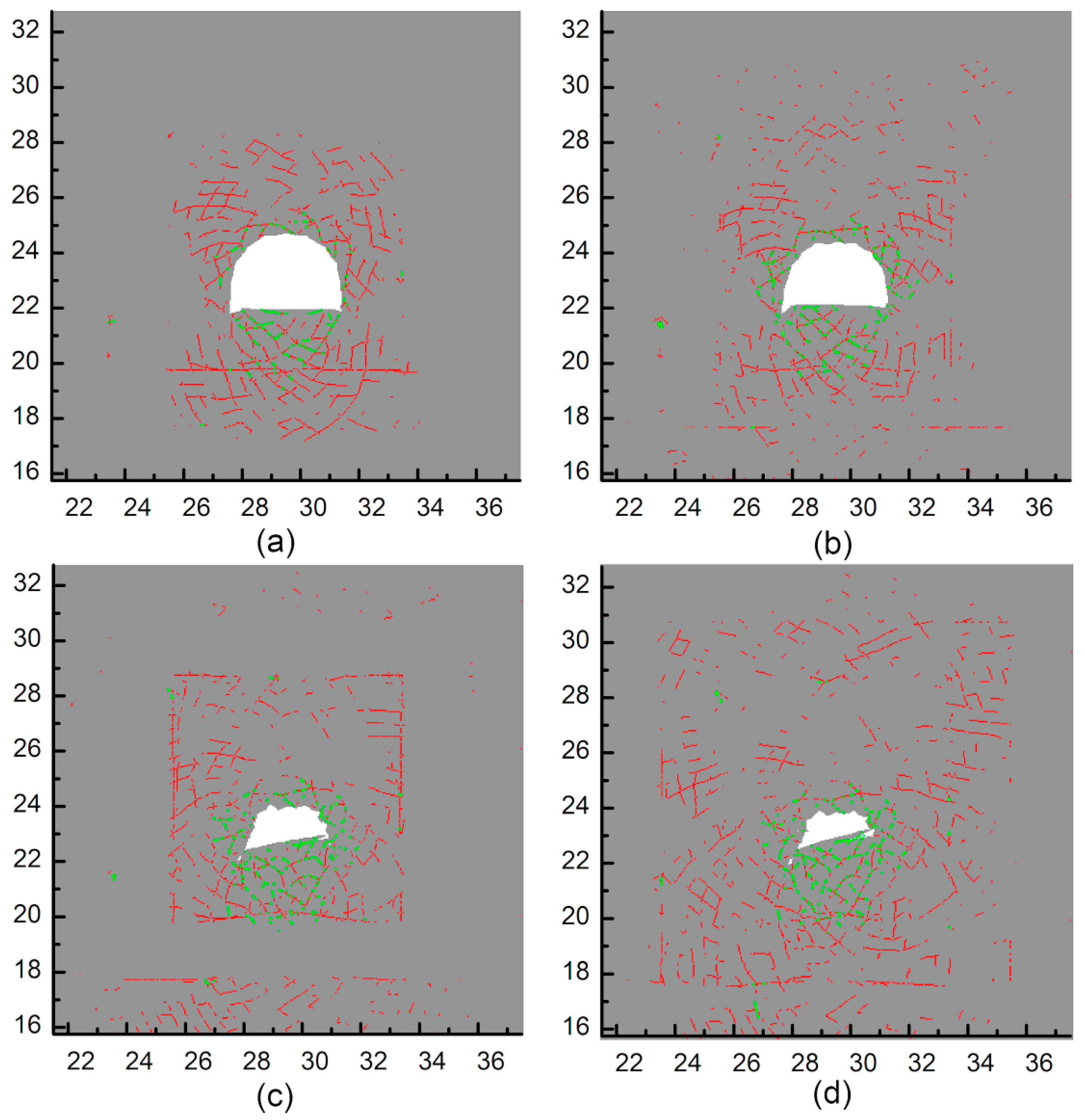
Figure 16.
Distribution of plastic zones within surrounding rock of the roadway.
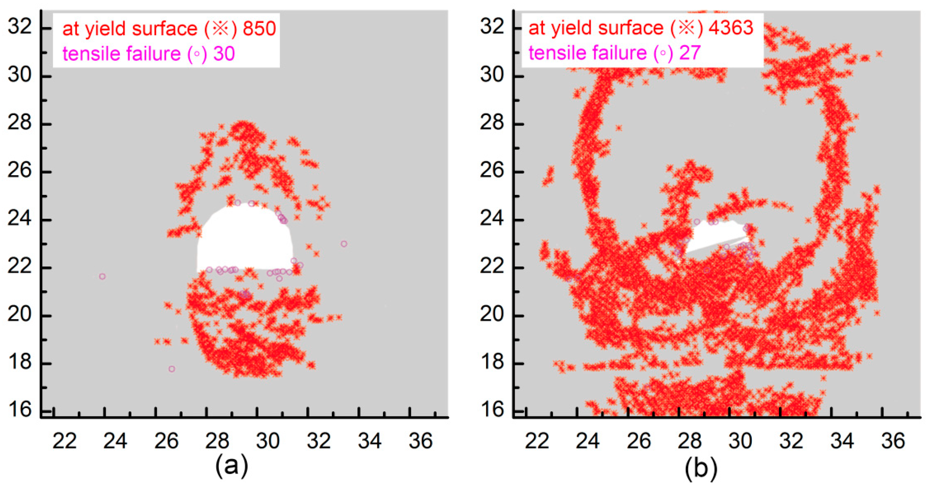
Figure 17.
Schematic diagram of the employed combined support approach: (a) section of bolts and cables; (b) section of grouting bolts; (c) placement layout (unfolded) for the roadway roof and two sides.
Figure 17.
Schematic diagram of the employed combined support approach: (a) section of bolts and cables; (b) section of grouting bolts; (c) placement layout (unfolded) for the roadway roof and two sides.

Figure 18.
Simulated principal stress distribution within surrounding rock in the case of the new combined support approach: (a) maximum principal stress; (b) minimum principal stress.
Figure 18.
Simulated principal stress distribution within surrounding rock in the case of the new combined support approach: (a) maximum principal stress; (b) minimum principal stress.
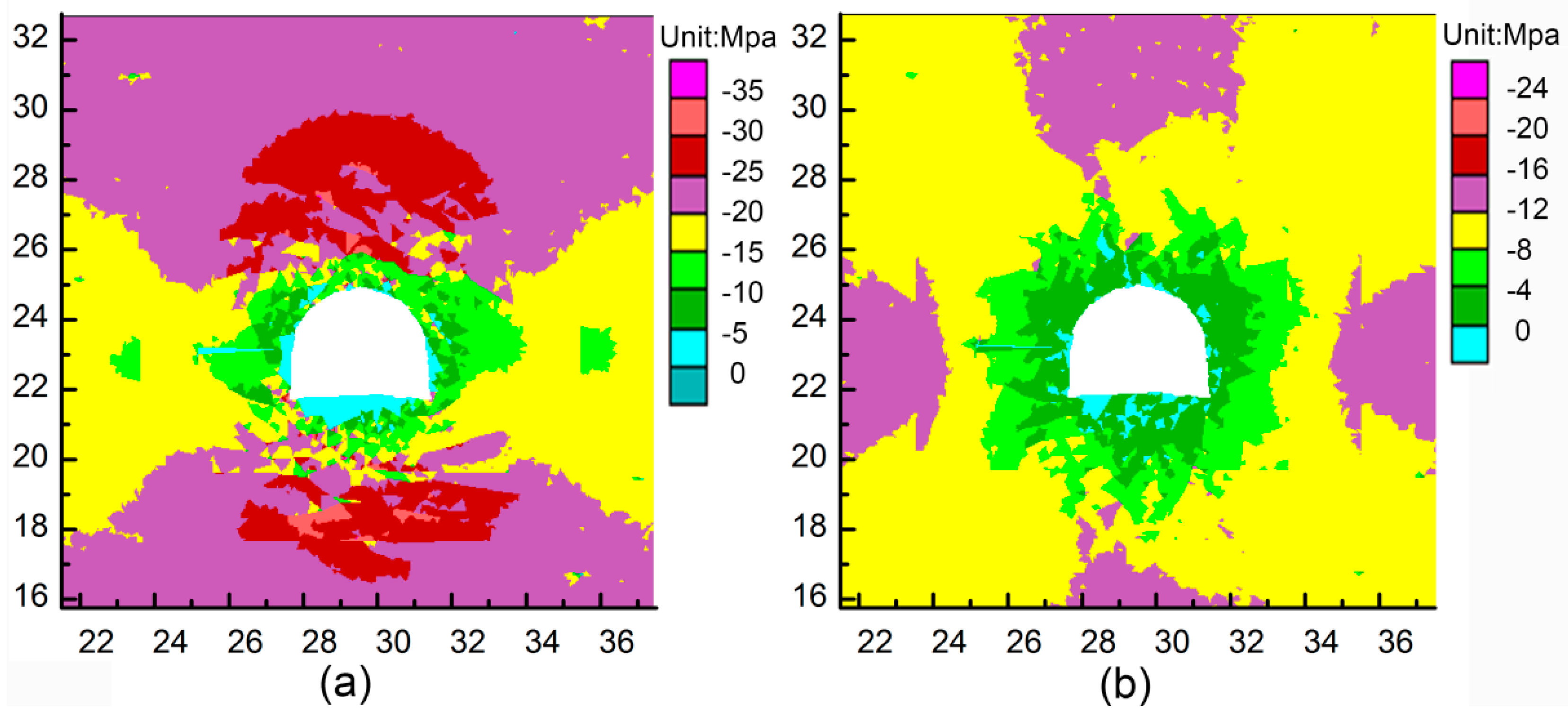
Figure 19.
Failure and displacement within surrounding rock in the case of the new combined support system: (a) plastic zone distribution; (b) displacement vector mapping.
Figure 19.
Failure and displacement within surrounding rock in the case of the new combined support system: (a) plastic zone distribution; (b) displacement vector mapping.
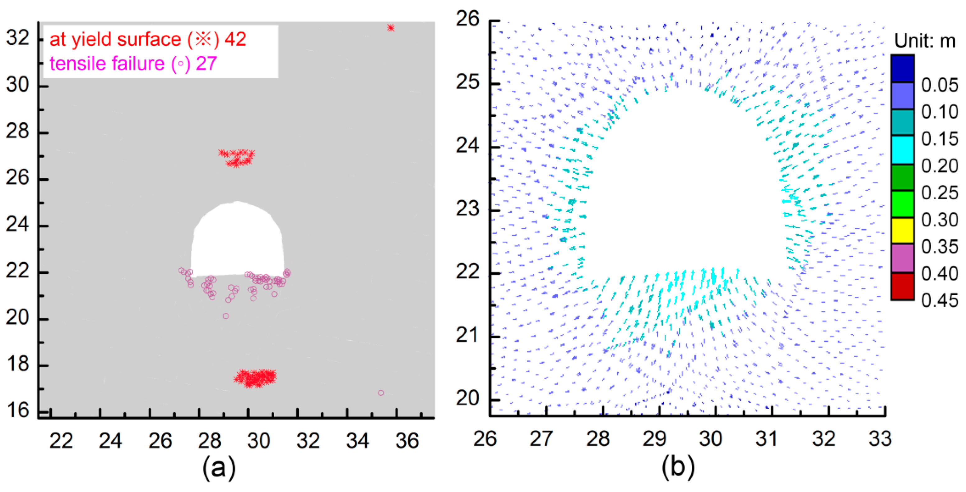
Figure 20.
(a) Displacement convergence of the -415 traveling roadway obtained by monitoring; (b) photograph of the roadway with the new combined support system.
Figure 20.
(a) Displacement convergence of the -415 traveling roadway obtained by monitoring; (b) photograph of the roadway with the new combined support system.


Table 1.
Intact rock properties and calculated rock mass properties. GSI—geological strength index.
| Lithology | Intact Rock | GSI | Constant | Rock mass | ||||||
|---|---|---|---|---|---|---|---|---|---|---|
| σci (MPa) | μ | mi | D | mb | s (10−5) | a | σcmass (MPa) | Emass (MPa) | ||
| Siltstone | 10.75 | 0.27 | 42 | 8 | 0.6 | 0.4149 | 31.73 | 0.5099 | 3.82 | 1.69 |
| Sandstone | 14.6 | 0.24 | 40 | 5.14 | 0.6 | 0.2407 | 24.04 | 0.5114 | 2.81 | 1.29 |
| Water-saturated sandstone | 4.656 | 0.244 | 38 | 3 | 0.7 | 0.0543 | 2.54 | 0.5273 | 1.22 | 0.70 |
| Weathered sandstone | 1.923 | 0.245 | 27 | 0.015 | 0.9 | 1.31 × 10⁻⁴ | 0.93 | 0.5273 | 0.70 | 0.20 |
| 7# coal | 5.24 | 0.25 | 30 | 3 | 0.6 | 0.0843 | 5.99 | 0.5223 | 1.32 | 0.51 |
Table 2.
Calibrated parameters for blocks and contacts.
| Lithology | Properties of blocks | Properties of Contacts | |||||||||
|---|---|---|---|---|---|---|---|---|---|---|---|
| Density (kg/m3) | K (GPa) | G (GPa) | Cb (MPa) | φb (°) | σtb (MPa) | kn (GPa) | ks (GPa) | Cj (MPa) | φj (°) | σtj (MPa) | |
| Siltstone | 2650 | 1.082 | 0.6809 | 1.72 | 30 | 1.3 | 159.218 | 63.6876 | 0.9 | 30 | 0.26 |
| Sandstone | 2700 | 0.827 | 0.520 | 1.3 | 25 | 0.8 | 121.764 | 48.706 | 0.8 | 25 | 0.2 |
| Water-saturated sandstone | 2620 | 0.451 | 0.283 | 0.76 | 21 | 0.74 | 66.319 | 26.528 | 0.33 | 23 | 0.14 |
| Weathered sandstone | 1360 | 0.1301 | 0.082 | 0.2 | 19 | 0.38 | 19.146 | 7.658 | 0.21 | 19 | 0.1 |
| #7 coal | 1400 | 0.325 | 0.204 | 0.785 | 25 | 1 | 47.806 | 19.122 | 0.356 | 25 | 0.2 |
| Grouting sandstone | 2940 | 0.835 | 0.525 | 0.958 | 21 | 1.7 | 122.865 | 49.146 | 0.657 | 22 | 0.16 |
Table 3.
Properties of bolts and cables employed in Universal Discrete Element Code (UDEC).
| Parameters | Density (kg/m3) | Young’s Modulus (GPa) | Tensile Yield Force (kN) | Bond Strength (N/m) | Bond Stiffness (N/m2) |
|---|---|---|---|---|---|
| Bolt | 7500 | 200 | 140 | 4 × 10⁵ | 2 × 10⁹ |
| Cable | 7500 | 200 | 320 | 4 × 10⁵ | 2 × 10⁹ |
Table 4.
Material properties of the new support system simulated in UDEC.
| Parameters | Density (kg/m3) | Elastic moduli (GPa) | Tensile capability (kN) | Bond Strength (N/m) | Bond Stiffness (N/m2) | Pretension (kN) |
|---|---|---|---|---|---|---|
| Bolt | 7500 | 200 | 140 | 4e5 | 2e9 | 60 |
| Cable | 7500 | 200 | 300 | 4e5 | 2e9 | 120 |
| Grouting bolts in roof | 7500 | 200 | 127 | 4e5 | 2e9 | 60 |
| Grouting bolts in floor | 7500 | 200 | 80 | 4e5 | 2e9 | 0 |
Table 5.
Properties of concretes in UDEC.
| Parameters | Thickness (mm) | Elastic Moduli (GPa) | Compressive Strength (MPa) | Tensile Strength (MPa) | Contact Normal Stiffness (GPa/m) | Contact Shear Stiffness (GPa/m) |
|---|---|---|---|---|---|---|
| Shotcrete in roof | 200 | 25 | 70 | 50 | 10 | 10 |
| Concrete in floor | 300 | 35 | 150 | 100 | 20 | 20 |
© 2019 by the authors. Licensee MDPI, Basel, Switzerland. This article is an open access article distributed under the terms and conditions of the Creative Commons Attribution (CC BY) license (http://creativecommons.org/licenses/by/4.0/).
Share and Cite
MDPI and ACS Style
Xue, G.; Gu, C.; Fang, X.; Wei, T. A Case Study on Large Deformation Failure Mechanism and Control Techniques for Soft Rock Roadways in Tectonic Stress Areas. Sustainability 2019, 11, 3510. https://doi.org/10.3390/su11133510
AMA Style
Xue G, Gu C, Fang X, Wei T. A Case Study on Large Deformation Failure Mechanism and Control Techniques for Soft Rock Roadways in Tectonic Stress Areas. Sustainability. 2019; 11(13):3510. https://doi.org/10.3390/su11133510
Chicago/Turabian StyleXue, Guangzhe, Chao Gu, Xinqiu Fang, and Tao Wei. 2019. "A Case Study on Large Deformation Failure Mechanism and Control Techniques for Soft Rock Roadways in Tectonic Stress Areas" Sustainability 11, no. 13: 3510. https://doi.org/10.3390/su11133510
Note that from the first issue of 2016, this journal uses article numbers instead of page numbers. See further details here.