Article

Surveying and Digital Restoration of Towering Architectural Heritage in Harsh Environments: a Case Study of the Millennium Ancient Watchtower in Tibet

1
Architecture Department, Xi’an University of Architecture & Technology, No. 13, Yanta Road, Xi’an 710055, China
2
Architecture Department, Chang’an University, No. 161, Chang’an Road, Xi’an 710061, China
3
School of Remote Sensing and Information Engineering, Wuhan University, No. 129, Luoyu Road, Wuhan 430079, China
*
Authors to whom correspondence should be addressed.
Sustainability 2018, 10(9), 3138; https://doi.org/10.3390/su10093138
Submission received: 12 August 2018 / Revised: 24 August 2018 / Accepted: 31 August 2018 / Published: 3 September 2018
(This article belongs to the Special Issue Digital Heritage)

Abstract

:
Aiming at the problem of difficult data collection and modeling in high-rise ancient buildings with narrow interiors, a method is proposed in this paper for modeling and supporting digital restoration based on unmanned aerial vehicle oblique photogrammetry combined with three-dimensional (3D) laser scanning technology. The ancient watchtower complex in the Tibetan region of China is taken as an example. Firstly, the data is collected using an unmanned aerial vehicle and 3D laser scanner. Secondly, the two types of data are merged to generate a three-dimensional status model. Finally, by analyzing the status model and combining the similar remaining conditions, a virtual restoration scheme is proposed, and a 3D restoration model is established. The results show that virtual restoration based on 3D measurement technology can be used as a new method for the research and protection of towering ancient buildings, asrecorded by adopting targeted technology for digital documentation. It is necessary and effective to adopt a method combining unmanned aerial vehicle oblique photogrammetry and the ground 3D laser scanning technology in harsh environments. The digital model can promote the sustainable utilization of cultural heritage. It is necessary to analyze and make full use of the status model of such ancient buildings based on accurately measured data for the virtual restoration of the damaged ancient buildings. The status model of the ancient buildings can be used for display browsing and disaster recording. The restoration model can be dismantled and used to guide the repair work.

1. Introduction

As cultural heritage is the cultural wealth of all mankind, rich and diverse cultural heritage should be protected by adopting targeted technology. With the development of remote sensing technology, a new data capturing method can provide significant convenience for the digital recording and display of cultural heritage. Most of the immovable cultural heritage is archaeological sites and ancient buildings. At present, unmanned aerial vehicle (UAV) aerophotogrammetry [1,2] is mainly used for relatively wide and flat archaeological sites and industrial heritage with simple form, for which the quality of the results is higher. Satellite image photogrammetry [3,4] is also used for monitoring and analysis, for which the accuracy of the results is limited. Photogrammetry [5,6,7,8,9,10,11,12,13], three-dimensional (3D) laser scanning [14,15,16,17,18,19,20], or a combination of both methods [21,22,23,24,25,26] is generally used for ancient buildings, for which the surveying and mapping results can be used for post-display, analysis, and evaluation [27,28,29,30,31].
In the above cases, the unmanned aerial vehicle is undoubtedly the best way to achieve the most convenient and cost-effective objectives. However, since ancient buildings are more complex than archaeological sites and the surveying of internal and external geometric data is more susceptible to the surrounding environment, most of the above operations are only suitable for open space or single buildings with simpler structures. For towering ancient buildings with a narrow internal space, there is no perfect technical route on how to do well in surveying and mapping with regards to ensuring the safety of personnel, equipment, cultural relics, and other aspects. Also, it is necessary to investigate and evaluate whether the unmanned aerial vehicle can be effectively applied to such cultural heritage. Moreover, for ancient buildings or ancient architectural complexes with more complicated structures, there are few related studies currently existing on how to effectively integrate the internal and external data [32]. Using a convenient and reliable method to implement the virtual reconstruction of cultural heritage is necessary [33].
As is known to all, China’s Tibet is a world-famous, high-altitude region with very harsh climatic environments, frequent earthquakes, and other natural disasters. There are unprecedented problems for archaeological research and protection in this environment. In April–October 2017, the Chang’an University and the Wuhan University were invited by the Tibet Nyingchi City Bureau of Cultural Relics to make a comprehensive survey and map of an ancient watchtower complex in Tibet. However, the site environment was very dangerous, and the stones might have collapsed and fallen from the top of the towering and fragile watchtower at any time. However, the task was successfully accomplished by using a variety of surveying methods made possible by the unmanned aerial vehicle. On 18 November 2017, a 6.9 magnitude earthquake occurred in Nyingchi City, Tibet. The epicenter was located at 29.75° N and 95.02° E. Many important cultural heritage sites, including the watchtower, were severely damaged. Fortunately, the data collected previously, with the help of this ancient watchtower complex, may provide an important and unique reference for the research, protection, and restoration of the watchtower after the earthquake. Using the digital model of watchtowers for education and display has substantially promoted the local culture and tourism levels, and also realized sustainable experience and research without destroying the site. It is very significant to carry out surveying, mapping, and research on watchtower-type ancient buildings under high-altitude conditions in China for the first time. There are more than 1000 watchtowers of the same type in China, and the research methods and experience can be used as an important reference for similar work. In this paper, using the research object (i.e., the Xiuba watchtower complex), the basic principles and working methods for the accurate measurement, three-dimensional modeling, and virtual restoration of the towering architectural heritage in the harsh environments of the plateau are described in detail.

2. Background

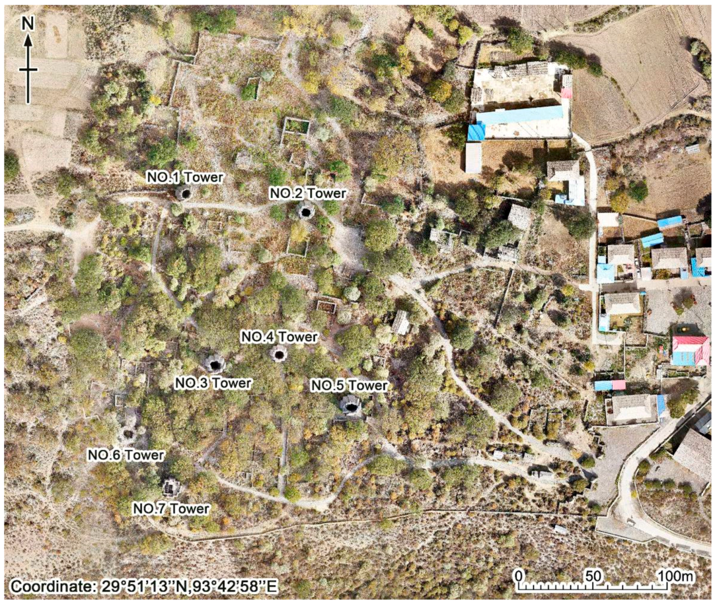
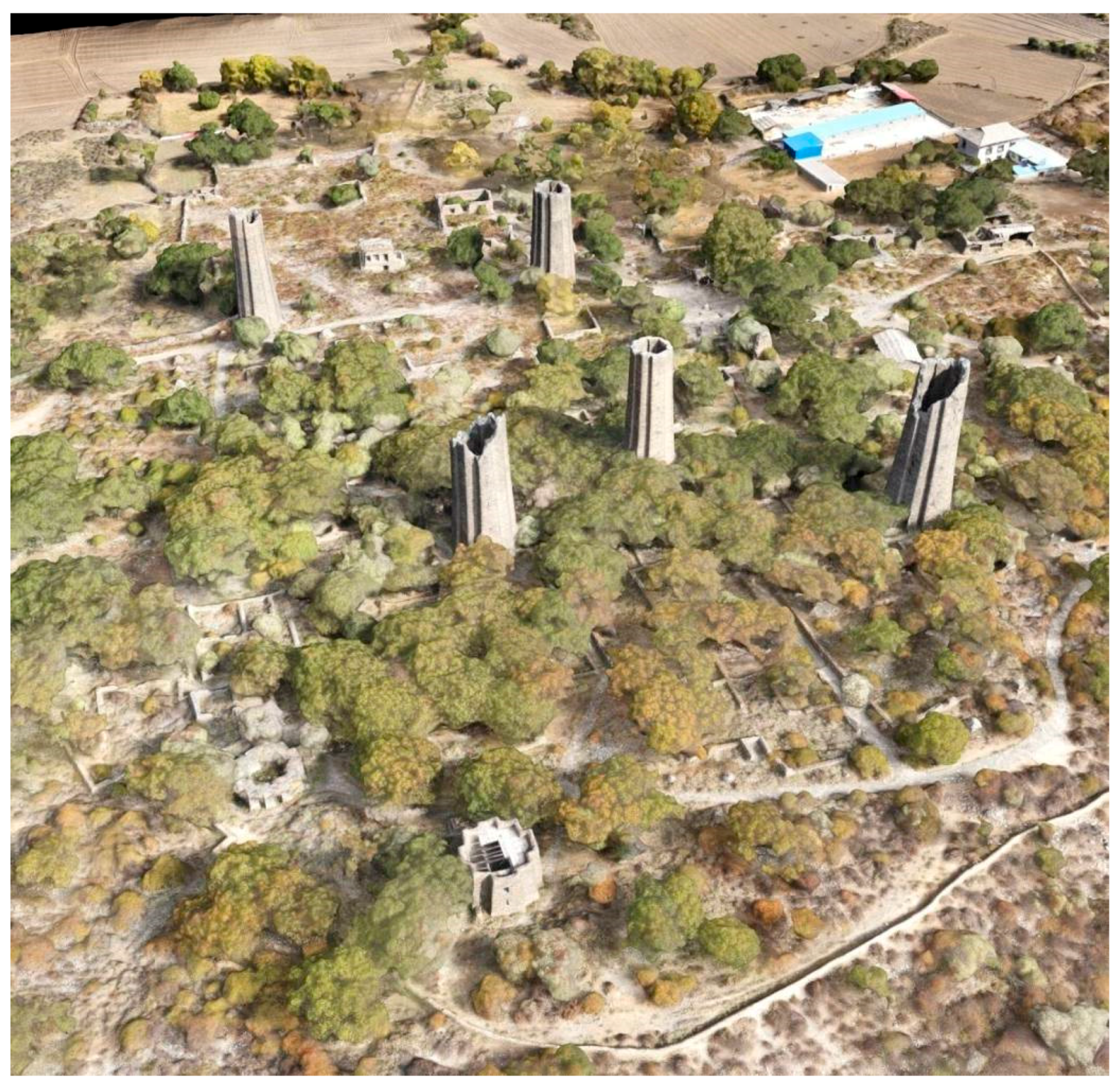
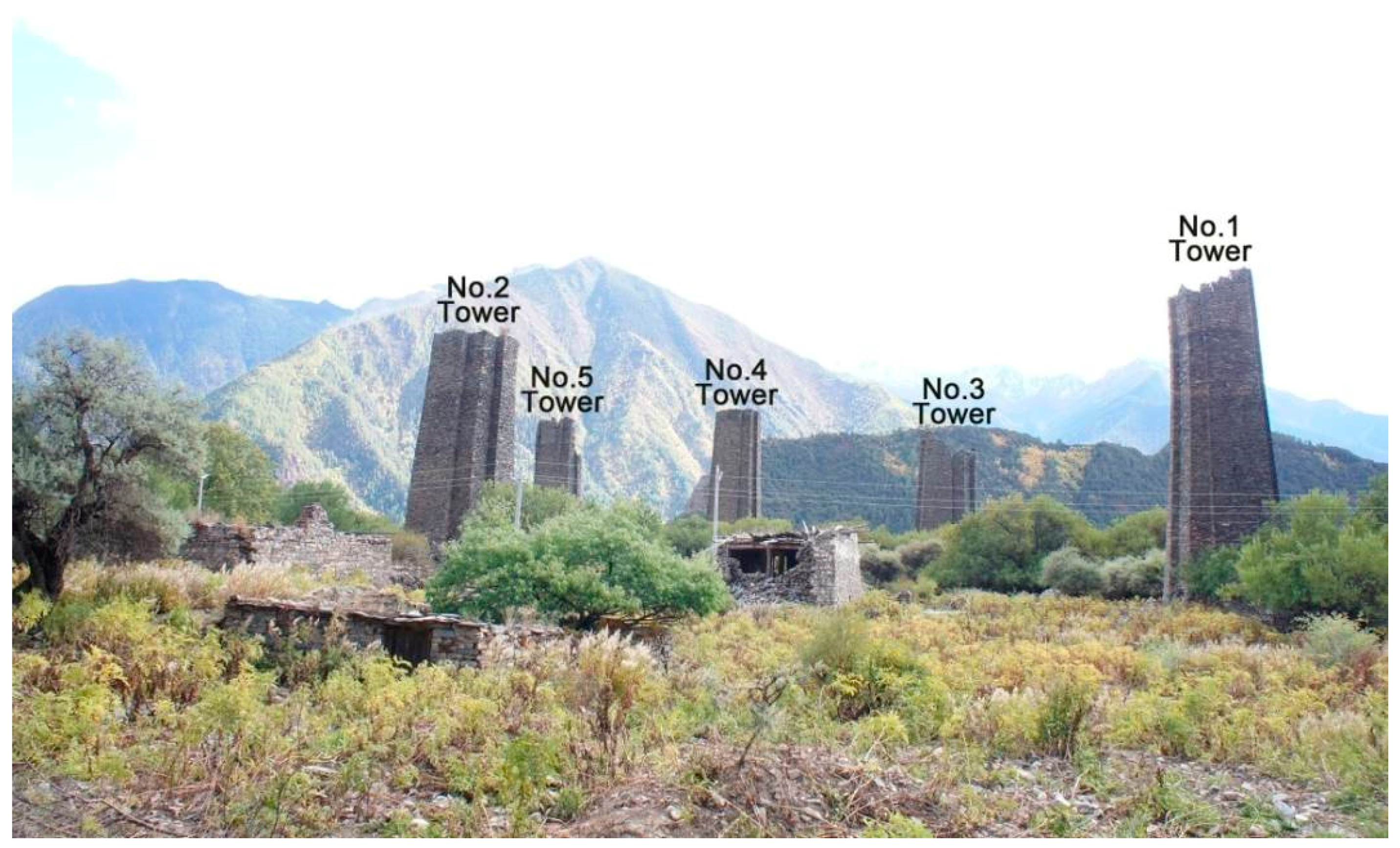
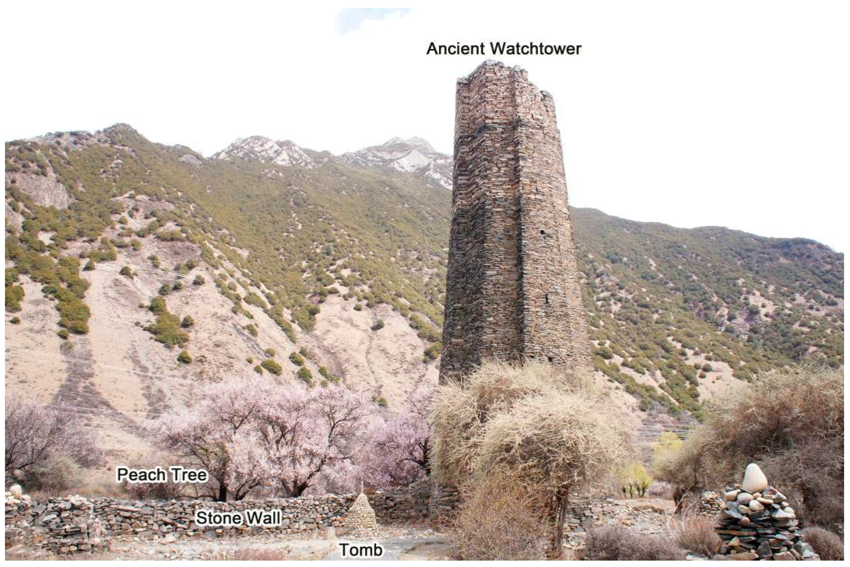
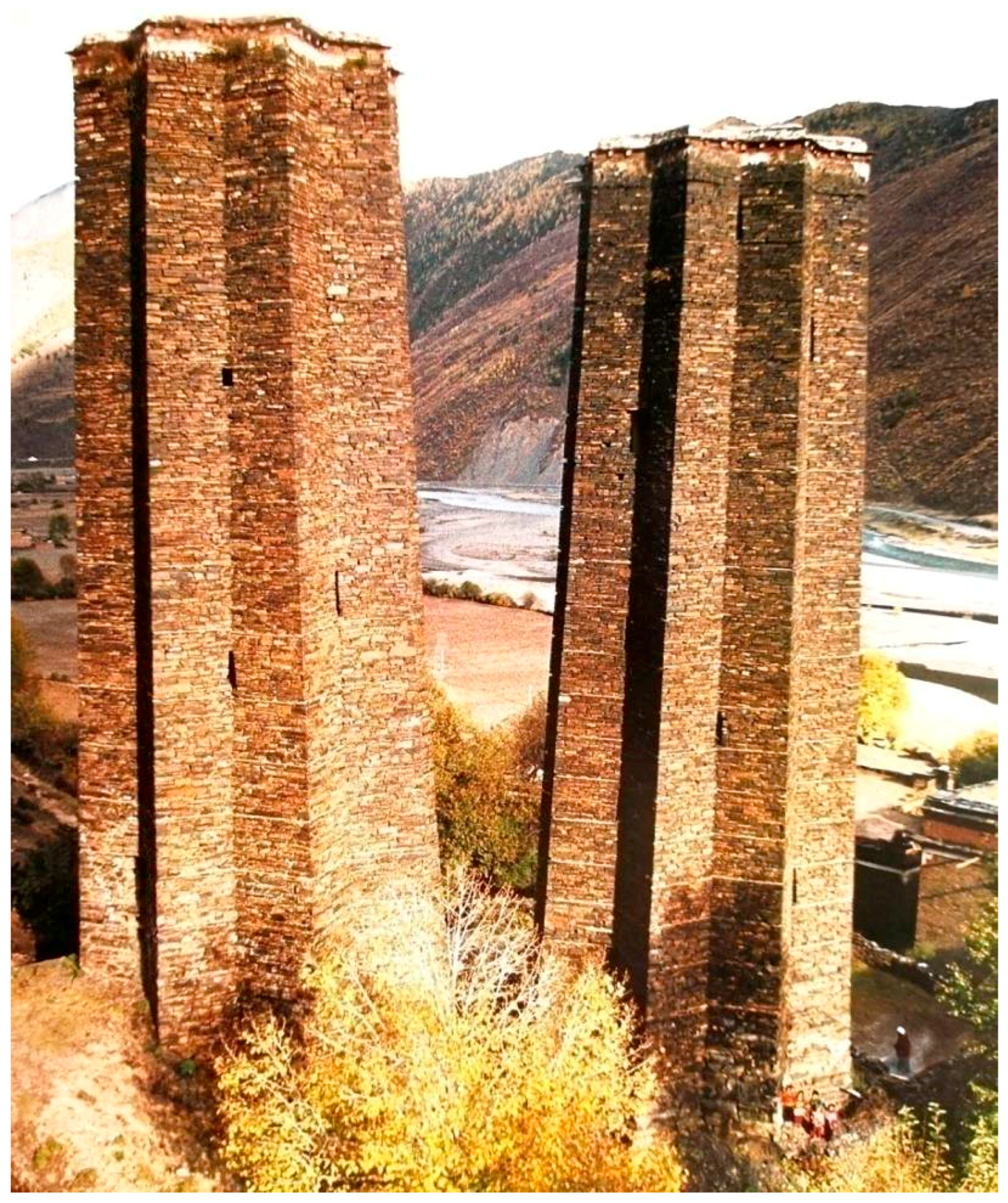
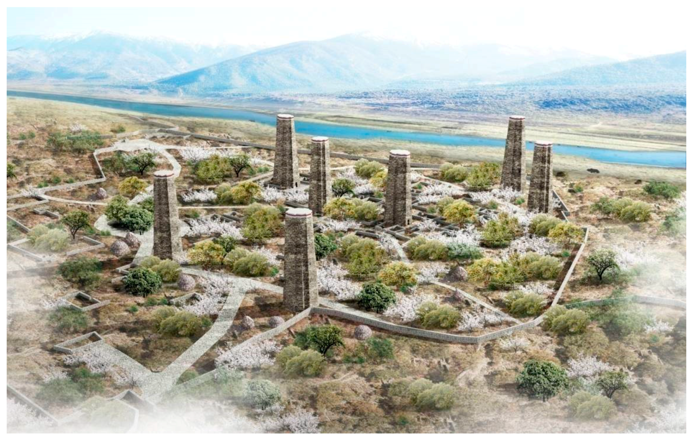
2.1. Overview of the Limestone Hall of the Xiuba Ancient Watchtower

Watchtowers are tall ancient structures made of natural stones and woods, and usually have stone masonry outside and wooden floors inside. This unique architecture is widely distributed in the plateau areas of Tibet and Sichuan, and is mostly built by Tibetans. According to historical records, this kind of building appeared more than 2000 years ago. There are many kinds of flat forms, but they are all tall towers. The function of the watchtower is not clear. It is generally believed that the Tibetan people built it next to the residential buildings for military defense, and it may also be used for mysterious religious sacrificial activities.
In western China, there were at least 10,000 watchtowers in ancient times, many of which collapsed due to weathering and man-made destruction, but there are still more than 1000 left. The ancient watchtowers are usually constructed from processed sheets of rocks in the local mountains, each about 20–60 cm in length, 10–20 cm in width, and generally no more than 10 cm in thickness. After being processed into a more regular shape, the rocks are easily used to build the walls of the watchtowers. Most ancient watchtowers consist of one tower; occasionally, they consist of two or more towers in parallel. In some of the watchtowers, small fire holes are found, suggesting that users can use the shooting weapons to form cross-defense through the collaboration between the watchtowers. Well-preserved watchtowers are rare in China, and the Xiuba Ancient Watchtowers in Gongbujiangda county, Nyingchi city, Tibet, is a typical case.
The Nyingchi Prefecture of Tibet has been an important hub for the exchange between the Central Plains dynasty of China and the Tibetan regime since ancient times. Through this area is where the magnificent Niyang River and the famous Tang–Tibet Ancient Road pass. Gongbo’gyamda County is an important traffic node from Nyingchi to Lhasa. Thousands of years of multi-ethnic exchanges and integration have left many historical and cultural relics in the region. The Xiuba ancient watchtower complex (Figure 1) is located in the canyon of Bahe Town, Gongbo’gyamda County. The site covers an area of approximately 4500 m2. A stone wall is built along the outer boundary of the site area, within which there are seven watchtowers with very similar floor plan shapes and building structures. Two of them have destroyed and only have the bottom remaining, and the other five watchtowers still exist, but their tops have collapsed (Figure 2). The residual height is approximately 20–27 m. The floor plan is in the shape of a quasi-mandala (i.e., “sub”-shaped). There are 12 corners formed inside and outside the wall, which is hollow without a top. A door is opened in the middle of the wall on one side of the first floor of the interior watchtower. The top of the door is horizontally embedded with several lumps of wood, which serve as the door lintel. The watchtower body is made of flat flaky stones. The appearance is polygonal prismatic in shape. The three to four rectangular lookout holes are vertically open on one side of some of the watchtowers. A circular wooden beam is placed at a certain height inside the watchtower (Figure 3). Most of the wooden beams have decayed. It is speculated that an original wooden floor was installed in the interior watchtower. The initial construction age of the watchtower complex is unknown. It is impossible to determine the age of construction by using the stones on the watchtower. However, the age of the wooden beam on the upper part of the watchtower door is determined by using C14 technology (because it is difficult to replace the wood at this section, and it was very likely built at the same time as the watchtower). The determined results show that the lower limit of the construction time of the seven watchtowers is different. The earliest construction time is not later than 780 AD, while the latest construction time is not later than 1470 AD [34]. This spans roughly from the late Tubo Dynasty to the Ming Dynasty.
Around the watchtower, there are many low stone walls that are approximately 1 m high and ca 0.6 m thick, and are made of flat stones and slabs conforming to the terrain. A number of architectural spaces are formed by the enclosure of low stone walls, which are usually shaped by connecting several small spaces to a large space. No traces of the pillars are found inside the enclosed space. The upper masonry surface of the low stone wall is also very flat. It indicates that this space is not a remnant of the house, but rather a fence wall matching the watchtower, which may be used as a temporary gathering place for the users of the watchtower. There are also many stone piles with a large lower part and a small upper part scattered around the wall called “Marnyi Stones”, which are the graves of Tibetans (Figure 4). Moreover, there are a large number of peach trees with a long history around the watchtower. Some peach trees are at least 500 years old, which can also be used as evidence for the construction era of the watchtower.
The Xiuba ancient watchtower complex is of important historical value and outstanding cultural value in terms of its construction age, building scale, and symbiotic environmental elements as a typical representative of ancient military fortresses in Tibet. This can provide the precious and credible material information for understanding and studying the Tibetan and Qiang watchtowers. In 2009, the Xiuba watchtower complex was listed as the fifth batch of cultural relic protection units in the Tibet Autonomous Region.
The Xiuba Watchtower Cluster is an important object of worship for local Tibetan people. It is the symbol of their belief, like snow, mountains, and lake water. Its existence can significantly enhance the cohesion of the residents in this area and promote the mutual understanding and solidarity among ethnic groups. At the same time, the Xiuba Watchtower Cluster, as the representative of the archaeological site in Nyingchi, is visited by a large number of non-local tourists every year, which greatly promotes local economic development. As a typical case of the watchtower building, the Xiuba Watchtower Cluster also provides necessary physical evidence for the study of the history and culture of Tibet. However, due to the recent earthquake damage, the status of the watchtower cluster is worrying, so we try to use the collected data for virtual restoration and digital display, in the hope of providing help for later repair work.

2.2. Research Objectives and Surveying Problems

2.2.1. Research Objectives

The objectives of this study are to accurately survey and map the seven watchtowers in the Xiuba watchtower complex, within the accuracy of a centimeter; survey and map the overall environment of the watchtower complex, within the accuracy of a decimeter; establish a digital three-dimensional status model that can be used for display and research; establish a three-dimensional virtual restoration model that can be used to guide protection and restoration work; and effectively reveal the appearance and internal structure of the watchtower under good conditions.

2.2.2. Problems Encountered

Due to the poor preservation of the Xiuba watchtower complex and the complexity of the natural environment, the difficulty in carrying out the related work increased significantly. There were three technical problems faced, which were as follows:
Problems encountered when surveying and mapping: Due to low temperature and more turbulent airflow within the plateau gorge area, how can the good operation of the unmanned aerial vehicle and other equipment be ensured? Due to many trees growing around the watchtower, how can occlusion by the trees be avoided to survey and map the exterior of the watchtower? Due to the age of the watchtowers, the structure is very fragile, and the internal space of the watchtower is relatively narrow. If people try to use scaffolding at work, it may cause rocks to tilt or collapse during the removal and construction of the scaffolding, endangering personnel. What’s more, the lower part of the watchtower is large, the upper part is small, and its walls are sloped, making it impossible to keep the crew at an ideal distance from the watchtower when building scaffolding. How can data be collected? Due to the dim light inside the watchtower, how can it be ensured that the collected images meet the requirements?
Problems encountered when establishing a model: As the collected data may be obtained by a variety of means, how can the multiple datasets be integrated to generate a status model of the watchtower? How can the virtual restoration model be established with the help of the status model?
Problems encountered when studying the virtual restoration model: As the interior of the watchtower has been completely damaged, how can the original appearance of the watchtower be ascertained based on the existing remains? As the top of the watchtower has been collapsed and damaged, how can the height of the watchtower be determined?

3. Research Strategies

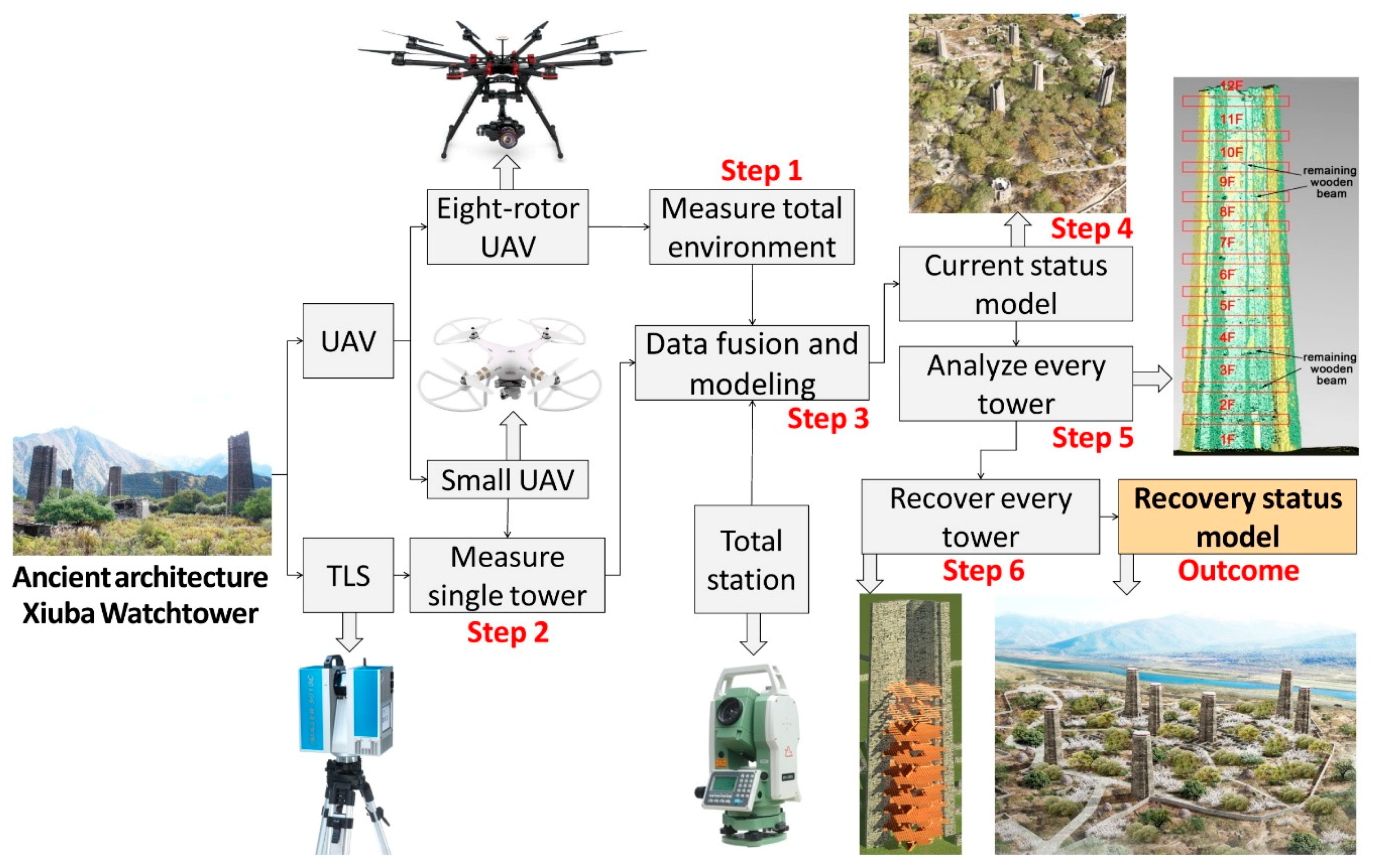
3.1. The Technical Flow Chart

In this study, the images of the surrounding environment of the watchtower complex were obtained by using an UAV for aerophotogrammetry. The data above and below the exterior of the watchtower was obtained by using the unmanned aerial vehicle and the three-dimensional (3D) laser scanner. The data above the interior of the watchtower were obtained by using the unmanned aerial vehicle via vertical take-off and landing photography under artificial auxiliary lighting conditions (by using high brightness lights and reflectors).The data of the interior lower part of the watchtower was obtained by using the 3D laser scanner. The coordinates of the indoor and outdoor control points were surveyed by using the total station; the internal and external point clouds of the watchtower were combined by using the Geomagic Studio software (Geomagic Inc., Research Triangle Park, Raleigh, NC, USA) via the coordinates of the control points to generate a triangulation network model. A three-dimensional status model with the geometric and color information of the watchtower was generated by texture mapping. Then, the restoration scheme was developed by analyzing the status model. The virtual restoration model was recreated with the help of the status model in the 3DS Max software (Autodesk Inc., San Rafael, CA, USA). This is all shown in Figure 5.

3.2. Specific Implementation Processes

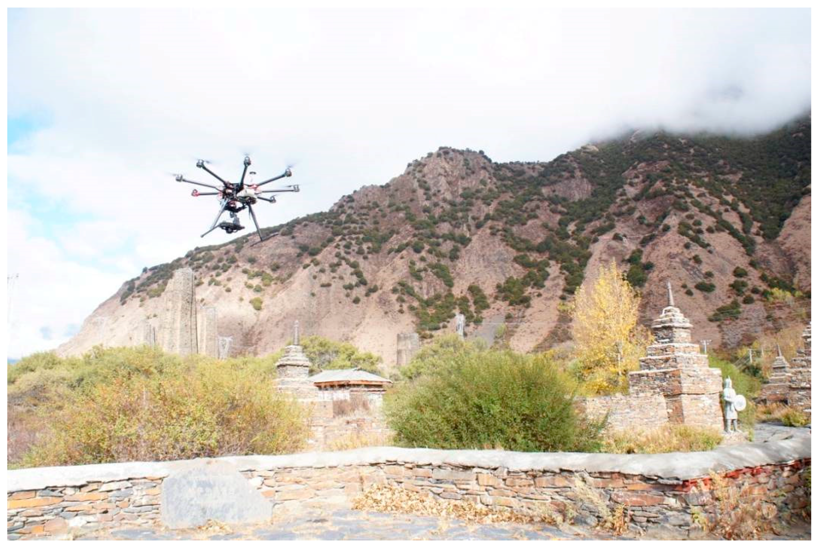
3.2.1. Collection of Data on the Overall Environment of the Watchtower Complex

The unmanned aerial vehicle was used to obtain the image data on the environment where the ancient complex is located. The aerophotographic control point was where the ground height difference was small and no trees blocked vision along the route direction. The coordinates of the control point were surveyed by using the total station. Special attention was paid to the airflow in the canyon during flight. The unmanned aerial vehicle must fly at a force of three or below wind speed; otherwise, it is easy to crash. Moreover, as the performance of the unmanned aerial vehicle battery is significantly reduced due to the low temperature in Tibet, the unmanned aerial vehicle must fly before and after noon. The battery needs to be replaced after every sortie. A large number of batteries should be prepared for replacement. The collected aerophotographic images were processed using the Smart3DCapture software (Acute3D Inc., Sophia Antipolis, France) so that the Digital Surface Model(DSM) point cloud data was generated after automatic system matching, aerial triangulation, and other steps. The Digital Terrain Model (DTM) point cloud data was obtained after the removal of interference. More detailed work implementation methods can be referred to in the literature [8,29].
The eight-rotor unmanned aerial vehicle was used for surveying and mapping the Xiuba watchtower (Figure 6); its model is DJI S1000 (DJI-Innovations Inc., Shenzhen, China). The distance between rotor shafts is 104.5 cm. The camera has a lens pixel of 24 million (manufactured by Zoller + Fröhlich Co., Ltd., Wangen, Germany). With consideration for the upper part of the watchtower, the flight height was set to 70 m. The image resolution was set to approximately 5 cm geometric standard deviation. There were a total of 12 sorties. The flight distance per sortie was set to approximately 600 m. The duration was set to 15 min. There were a total of more than 2800 images. The model of the total station is RTS342R6 (Suzhouyiguang Instrument Co., Ltd., Suzhou, China). The effective surveyed distance was 600 m in the prism-free mode. The accuracy of the survey control point coordinates was within ±2 mm (Root-Mean-Square error).

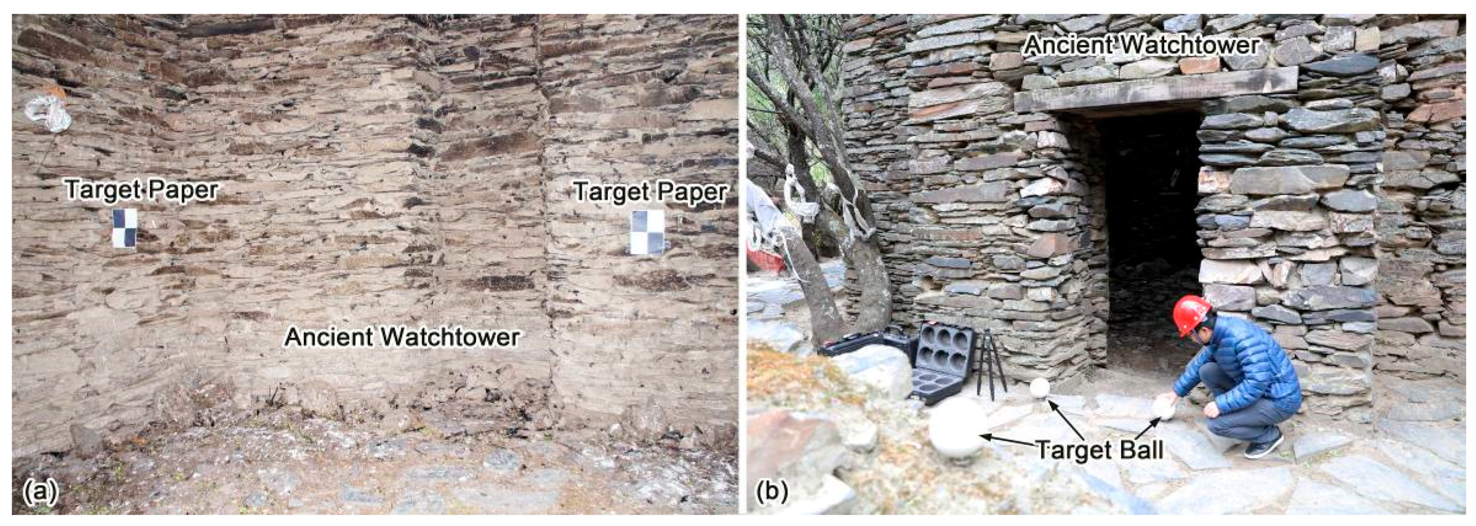
3.2.2. Layout and Survey of the Target

Before surveying each of the watchtowers, eight to 10 pieces of checkerboard target papers were placed in the visible external and internal positions of the watchtower (Figure 7a). The black and white intersection points of the checkerboard target papers were surveyed by using the total station. The relative coordinate system of the watchtower was established. A total of six pieces of target balls built in the FARO-type 3D laser scanner (FARO Technologies, Inc., Orlando, FL, USA)were laid in the visible area outside the watchtower (Figure 7b).

3.2.3. Collection of Data from the Exterior of a Single Watchtower

All of the personnel wore safety helmets before collecting the data. Although trees were a shelter from the exterior of the watchtower, the trees were lower than the height of the watchtower. Therefore, the part of the watchtower above the trees was surveyed by means of photogrammetry by using the manually operated and controlled multi-rotor unmanned aerial vehicle. The part of the watchtower below the trees was scanned by using a 3D laser scanner. Moreover, the position of the target ball was also scanned as required (Figure 8). In order to prevent the angle of elevation from becoming too large when scanning the watchtower and ensure the safety of personnel and equipment, an approximate distance from the watchtower was kept during operation by means of the two aforementioned methods. When taking photos with the unmanned aerial vehicle, special attention was paid to avoiding the watchtower and trees. Photos of the prelaid target papers and target balls were also recorded for later data fusion.
Due to the relatively narrow interior of the watchtower, the strong swirling airflow generated by the larger UAV interfered with the flight of the aircraft. Therefore, the small quadrotor UAV was used for surveying and mapping inside the watchtower. Its model is DJI Phantom3 (DJI-Innovations Inc., Shenzhen, China). The camera was manufactured by the aircraft manufacturer themselves, and had a lens of 16 million pixels. To prevent the aircraft propeller from touching the watchtower, a propeller protection ring must be installed onto the aircraft. The model of the 3D laser scanner was FAROFocus3D X330. In order to ensure the safety of personnel and equipment, during UAV control and 3D laser scanning, the operators should be in the central area of the interior of the watchtower. The duration of 3D laser scanning on each watchtower was approximately 30 min. The duration of the unmanned aerial vehicle aerophotogrammetry was approximately 30 min. The number of captured images was approximately 300–350. The image resolution was approximately 2 cm.

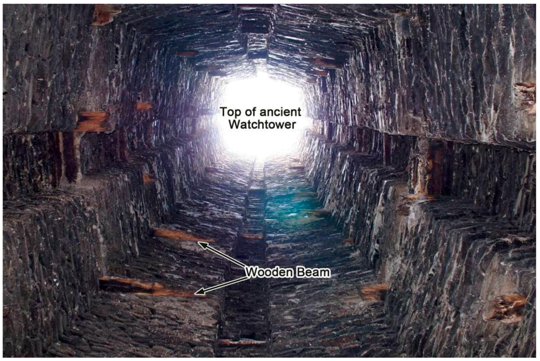
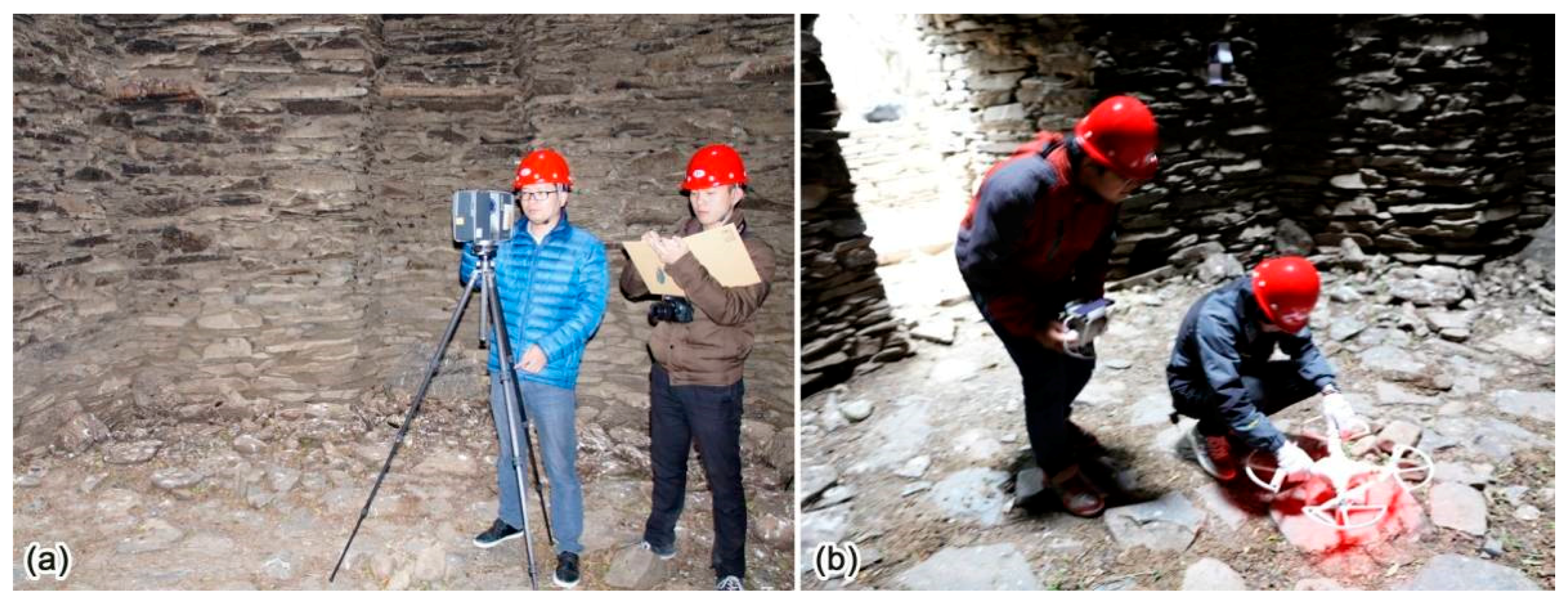
3.2.4. Collection of Data from the Interior of a Single Watchtower

The lower part of the interior of the watchtower was scanned using a 3D laser scanner (Figure 9a). Before scanning, the three internal target balls were moved into the watchtower. When surveying, the positions of the three internal or external target balls were scanned. Due to the excessive angle of elevation, the upper part of the interior of the watchtower was surveyed by means of photogrammetry with a camera carried in the unmanned aerial vehicle via manually operated vertical take-off and landing in the watchtower (Figure 9b). Moreover, the target papers placed inside the watchtower were also required to be photographed. In order to ensure the smooth integration of internal and external data, attention was focused on collecting the data on the door-opening parts at the junction between the interior and exterior of the watchtower during data collection.
The equipment used for the collection of data from the interior of a single watchtower is exactly the same as the equipment used for the collection of data from the exterior of the watchtower. The duration of 3D laser scanning on each watchtower was approximately 20 min. The scanning speed of 3D laser scanning was 976,000 points/s, and its optical resolution was 600 × 1200 dpi. The duration of the UAV aerophotogrammetry was approximately 30 min. The number of captured images was approximately 300–350.

3.2.5. Data Processing and Fusion and the Generation of Status Model

All of the data on the overall environment of the watchtower complex can be collected using the unmanned aerial vehicle, which can be automatically processed by Agisoft PhotoScan v1.2.6 software (Agisoft LLC., St. Petersburg, Russia) to generate the point cloud data. By generating the triangulation network and texture mapping, a three-dimensional digital model based on the real coordinate system and reflecting the overall environment of the watchtower can be generated. This file can be opened and edited using the 3D max software.
The data on a single watchtower was collected using the unmanned aerial vehicle and the 3D laser scanner. Fusion of the two kinds of data was one difficulty in this task. Firstly, the image data acquired by the unmanned aerial vehicle and the position information obtained by the measuring target point were imported into the Agisoft PhotoScan software (Agisoft LLC., St. Petersburg, Russia). After pre-processing by the software, the point cloud data (in the .xyz format) with the control point information was obtained. After the data acquired by the 3D laser scanner and the position information obtained by the measuring target point and the target ball were processed by Faro Scene v5.1 software (FARO Technologies, Inc., Orlando, FL, USA), the engineering file (in the .fws format) could be obtained, and the point cloud data (in the .xyz format) with the control point information could be exported. After pre-processing, the two sets of point cloud data (in the .xyz format) could be acquired, which share a set of control point information. After both were successively imported into the GeomagicStudio software (Geomagic Inc., Research Triangle Park, Raleigh, NC, USA), the two sets of point cloud data were automatically combined into a complete 3D point cloud model (Figure 10a,b). In translucent pattern (Figure 10b), we can clearly see the outer and internal wall surfaces the watchtowers (Figure 10c), and the wooden beams (Figure 10c) inserted into the interior wall. In this way, not only can the relationship between the wooden beams inside the watchtower and the external shape inside the watchtower be analyzed through the comparison of internal and external images, the number of floors inside the watchtower can be vaguely imagined also from the exterior of the watchtower (similar to X-ray radiation), which will facilitate the subsequent restoration research. The texture map generated by the unmanned aerial vehicle data processed by the Agisoft Photoscan software was directly mapped onto the 3D model in the GeomagicStudio software. Thus, the 3D model (in the .obj format) and the texture map (in the .mtl format) could be directly exported and opened and edited by using the 3D max software.
The accuracy of a single-watchtower model was higher, while the accuracy of the global environmental model of the watchtower complex was slightly lower. In the 3D max software, the precise model of each watchtower could be embedded into the global environmental model of the watchtower complex according to its actual distribution position so that the 3D status model could be obtained.

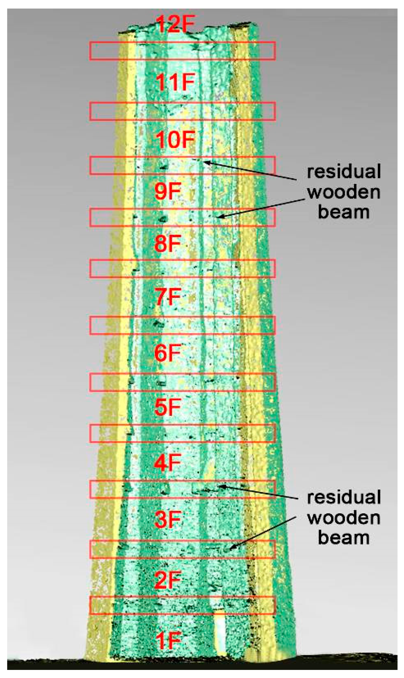
3.2.6. Analysis of the 3D Status Model and Proposal of the Virtual Restoration Scheme

By analyzing the 3D status model, combined with the relevant literature and other examples, the virtual restoration of the watchtower was studied. Similar methods have been used in the case of the Limestone Hall in Shaanxi province, China [30]. The original appearance of the damaged parts of the watchtower (including the internal wooden structure, top appearance or style, and other elements) was emphasized and analyzed.

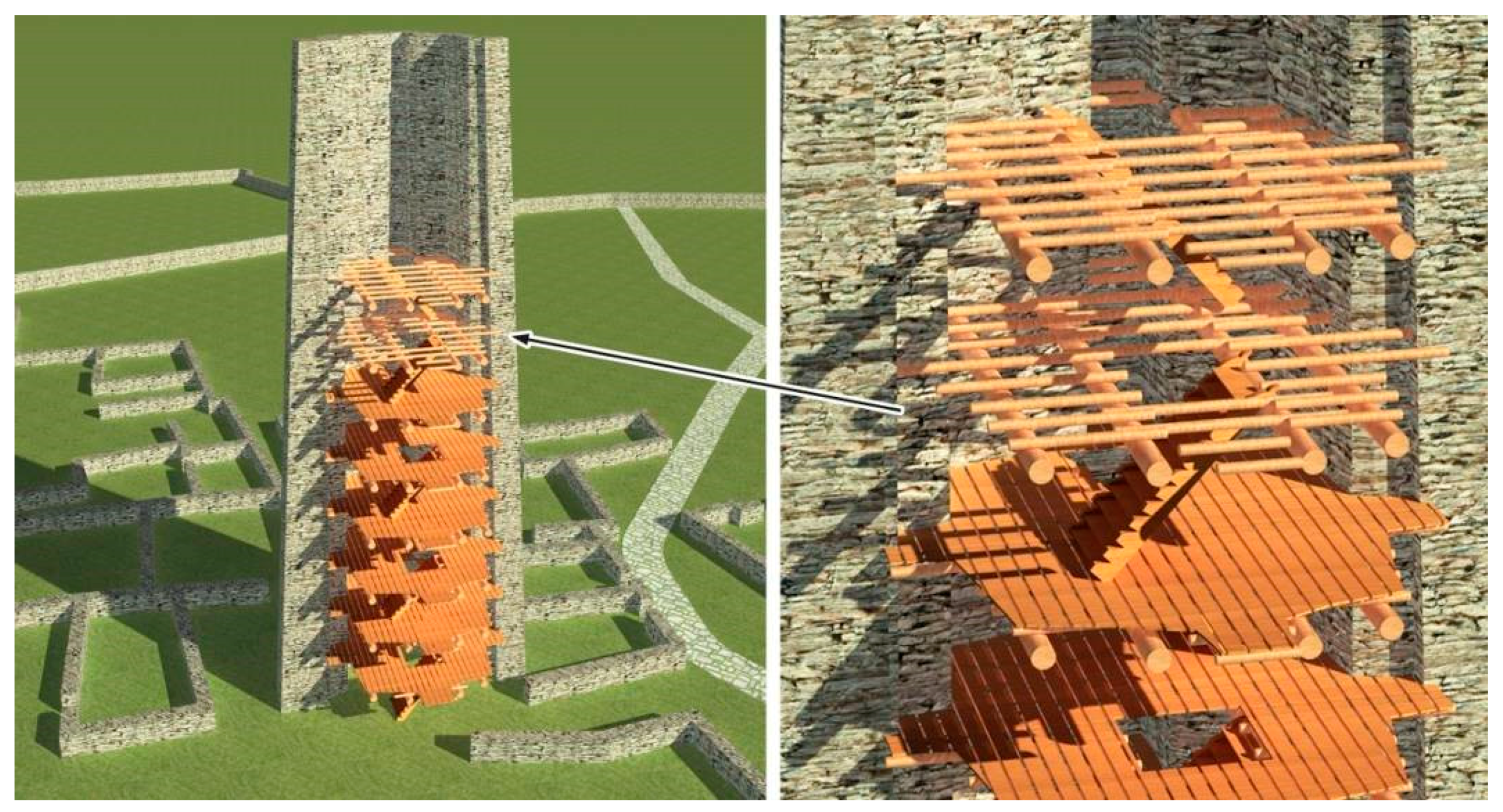
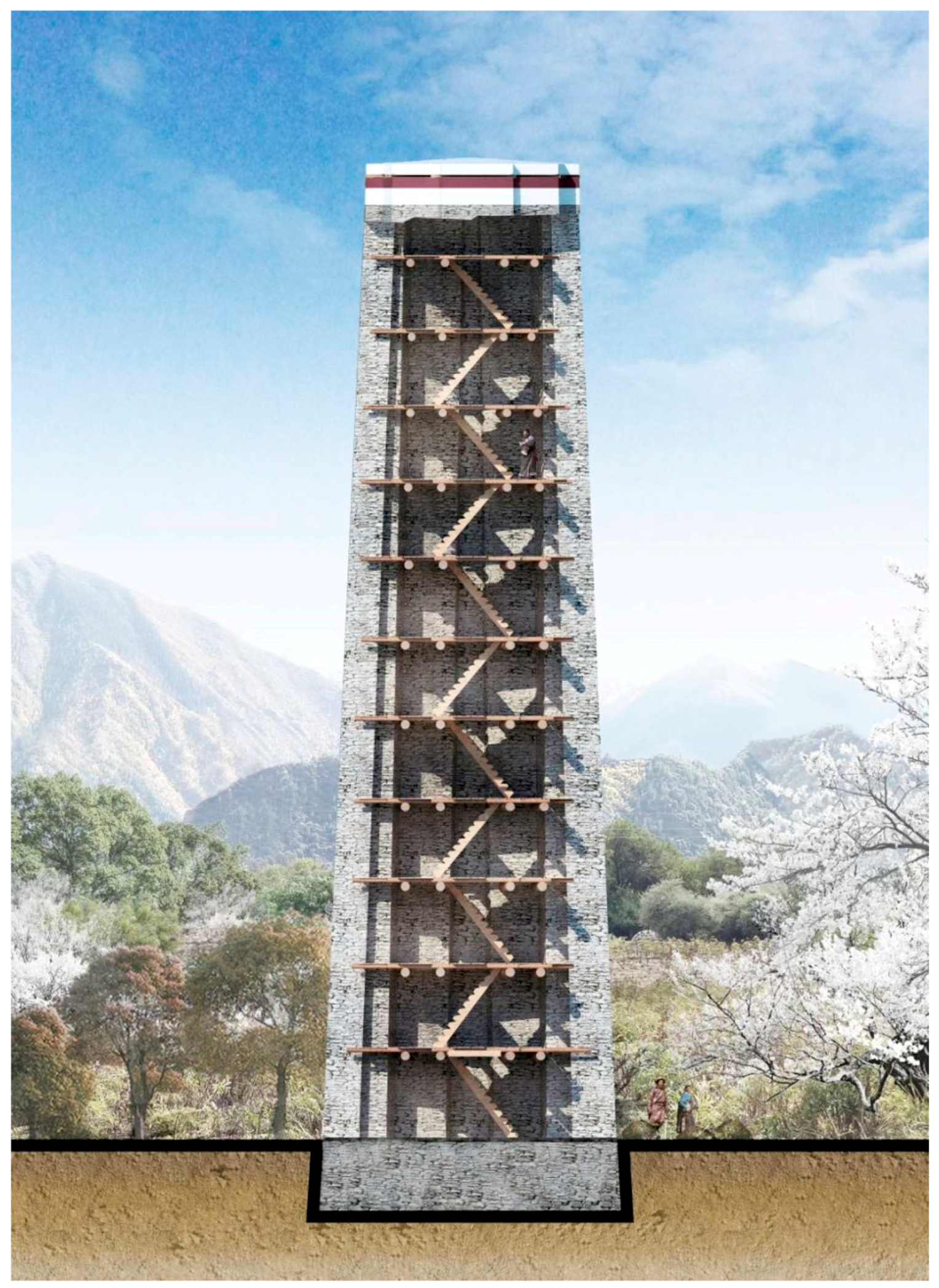
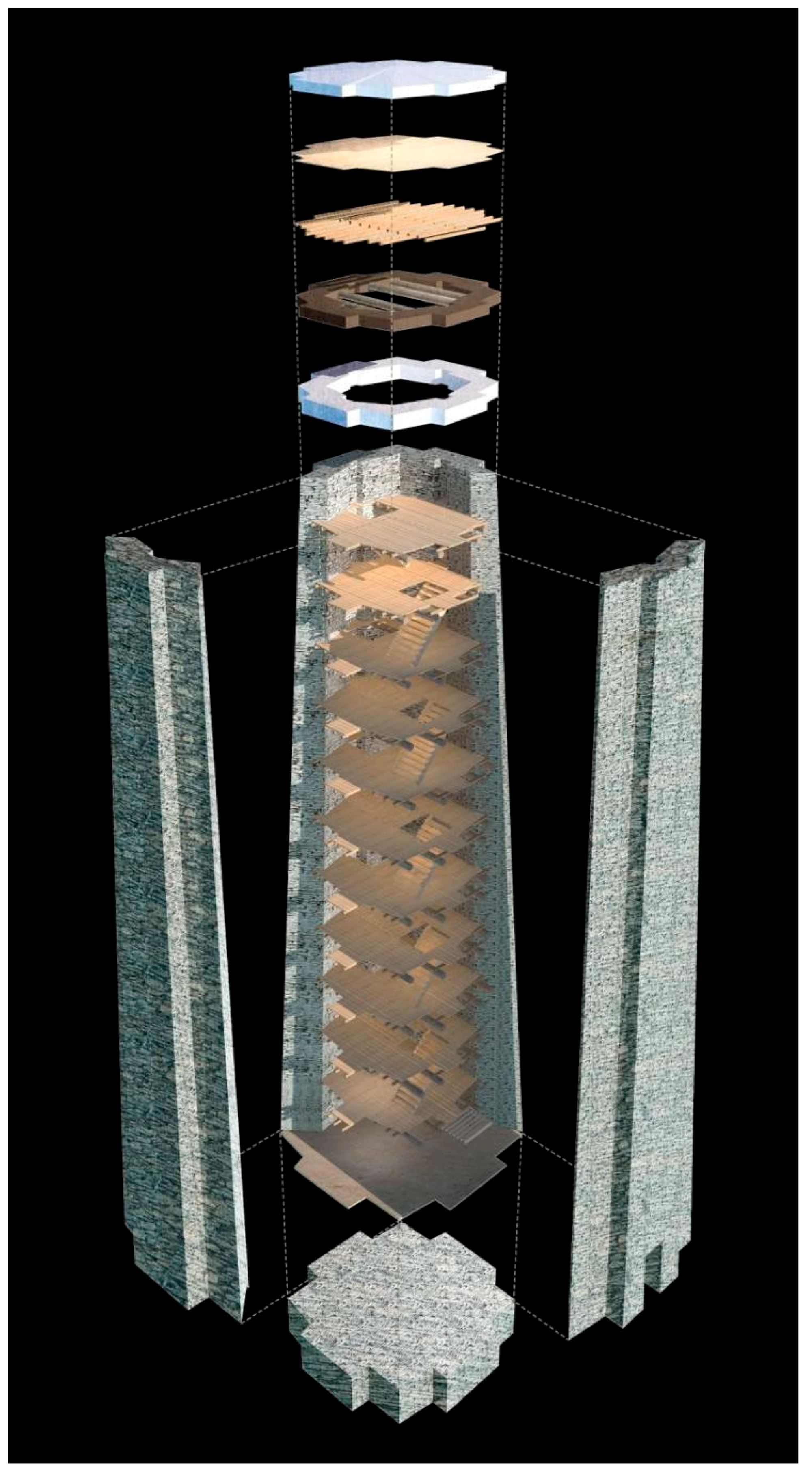
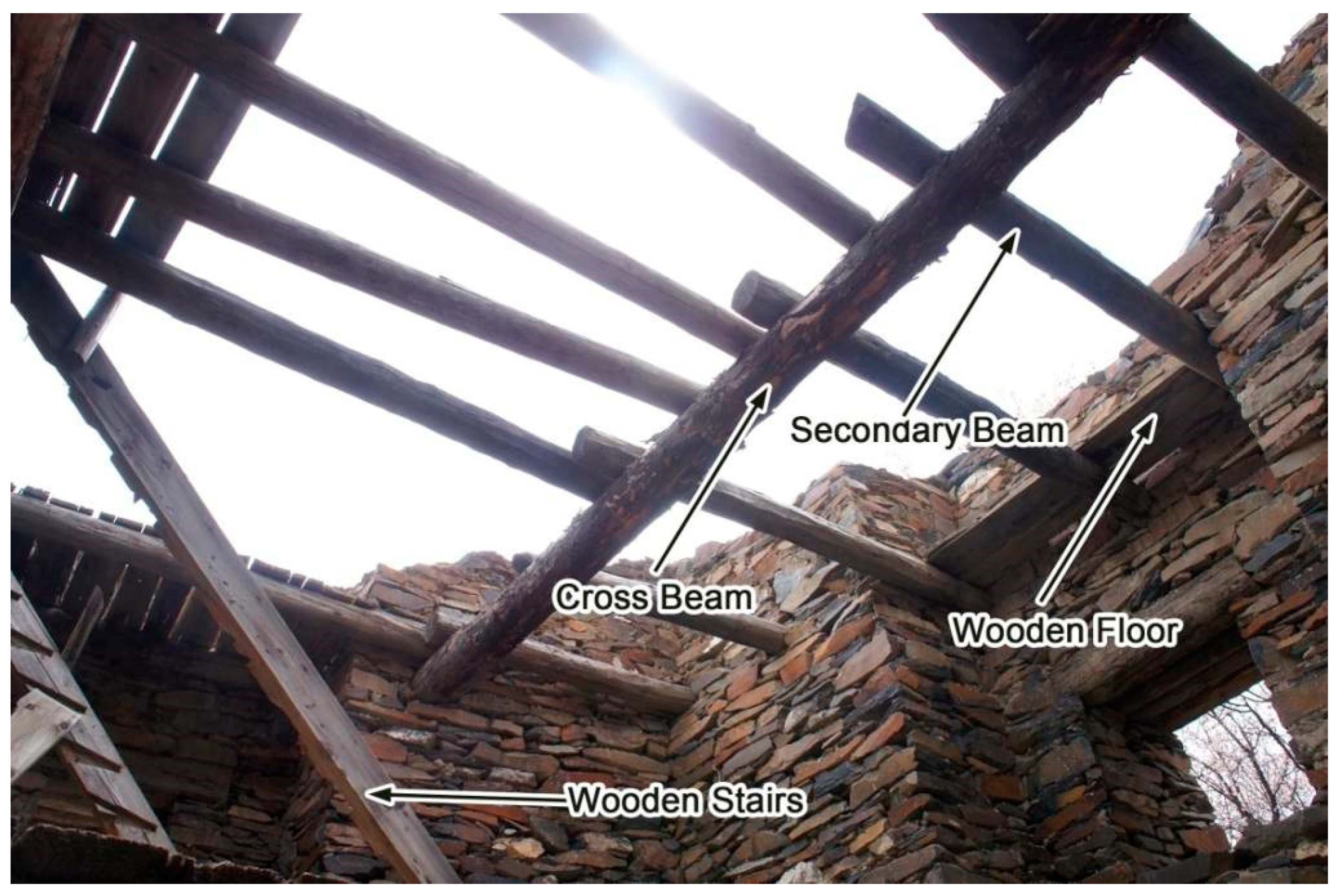
Internal Wood Construction Practices and Floor Distribution Rules

There is still a relatively complete wooden structure on the first floor of Xiuba watchtower No. 7, which can provide an important basis for restoration. It can be seen from Figure 11 that the floor slab of the watchtower is composed of a main beam, secondary beam, and plank. The main beam is penetrated into the interior in parallel and inserted into the interior of the stone wall. The secondary beam is divided into three sections, which are stacked in the vertical direction of the main beam. The main and secondary beams are made from logs. The plank is laid on the secondary beam. Moreover, there is a square stair hole on one side of each floor of the watchtower, and the wooden stair frame is set on the main beam or on the wall for access. Thus, a complete wooden structure building system inside the watchtower is formed. In combination with the data measured by the 3D laser scanner, according to the restoration scheme, the diameter of the main beam is set to an average of 27 cm. The diameter of the secondary beam is set to 12 cm. The thickness of the plank is set to 3 cm. The width of the watchtower is set to 96 cm.
Since the Xiuba watchtower has not been repaired for many years, there are different degrees of damage on the top of the watchtower. During restoration, the total height and the number of internal floors of the building should can speculated according to the status of the surviving buildings. It is worth noting that the top of watchtower No. 4 has barely collapsed, and the internal wooden beams are relatively completely preserved, which can accurately reflect the information on all of the floors of the building. The distribution of the wooden beams inside the watchtower can be clearly seen through the vertical section of the 3D status model of watchtower No. 4 (Figure 12). From this, the position of the floor and the number of floors can be determined. By measuring the height of each floor, it is found that there is some randomness in the distances, but the overall trend is decreasing. The average height of floors decreased by approximately 45 mm. The total height of the watchtower can be calculated according to this decreasing law. The highest level of the restored watchtower 4 is 2.12 m, and we believe that the other watchtowers should follow a similar pattern, with the highest level approaching 2.12 m, regardless of the number of floors. In addition, judging from the later watchtowers in other parts of Tibet, it is rare for the interior to have more than 14 floors. Based on the above principles, for other watchtowers, the number of floors and the total height of each watchtower (Table 1) can be calculated according to the slope of the wall, the position of the wooden beam, and the appearance of the watchtowers.

Style of the Roof of a Watchtower

The planar style of the Tibetan watchtower consists of shapes such as tetragons, octagons, dodecagons, and quasi-mandalas. The style of the roof of the watchtower is closely related to the floor planar style of the watchtower. The Shade watchtower (Figure 13), which was built 800 years ago in Kangding County, Ganzi Tibetan Autonomous Prefecture, Sichuan, has a similar floor planar style as the Xiuba watchtower. The roof of the Shade watchtower is relatively well preserved, which can be used as a key basis for the restoration of the roof of the Xiuba watchtower. The top of the virtual recovered Xiuba watchtower penetrates the interior with a wooden beam. The wooden ceiling is laying on the indoor wooden beam. The wooden beam protrudes out of the watchtower by 25 cm. The wooden beam is covered and enclosed with wooden boards and stones, and makes a slope by ramming the earth for drainage. In order to express respect for the gods, the wall at the bottom of the wooden beam on the top of the watchtower is built with red and white aggregated rocks.

3.2.7. Re-Establishment of the Restoration Model According to the Virtual Restoration Scheme

In the 3ds Max software (Autodesk Inc., San Rafael, CA, USA), with the help of the 3D status model, the watchtowers were remodeled one by one. The wall was repaired completely according to the set height of the watchtower. Then, the wooden beam, floor slab, floor body, ceiling, and other components were added inside the watchtower according to the set dimensions of components (Figure 14), so that the three-dimensional restoration model of the single watchtower could be obtained.
Moreover, the enclosure wall, Marnyi Stones, and other structures around the watchtower were also reconstructed in the model. After modeling the related structures, the figures, trees, flying birds, and other entourages were added to the three-dimensional model with the proper dimensions, in order to provide an intuitive scale reference for the watchtower and increase the fidelity of the scene.

4. Results and Related Discussion

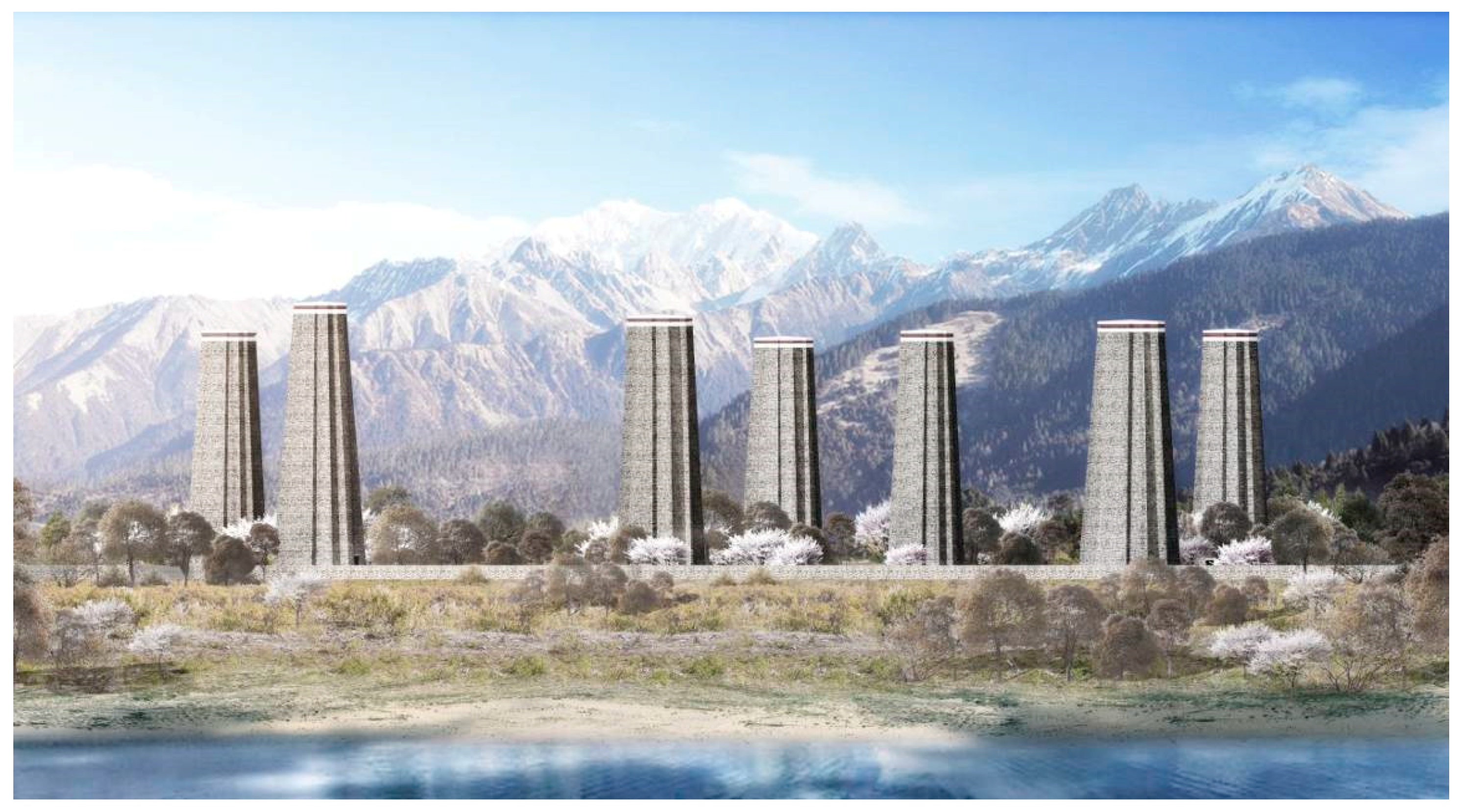
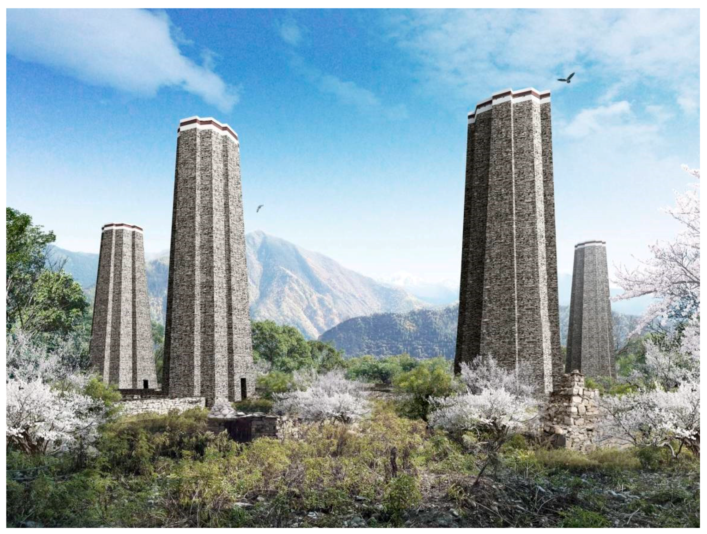
4.1. Current Status Model and Virtual Recovery Status Model

The 3D status model and the 3D restoration model of the Xiuba watchtower complex (both are generated after processing) (Figure 15) can be rendered by the 3Ds Max software to output a high-resolution rendering image. The environmental elements, such as snow, mountains, and rivers where the watchtower complex is located, can be added to the rendering image of the restoration model after precise processing using the Photoshop software (Adobe Systems Incorporated, San Jose, CA, USA) in order to obtain the more realistic renderings (Figure 16, Figure 17 and Figure 18). The 3D restoration model can also allow for a vertical cut display (Figure 19) and structural split display (Figure 20).

4.2. Discussion of the Results

4.2.1. Accuracy of the Status Model

After comparing the single 3D status model of the Xiuba watchtower with the real object for inspection, it was found that the accuracy of model was greater than 2 cm. The gap between the stones on the watchtower was clearly presented. The model map could more realistically reflect the current status of the watchtower. The colors of the rocks, ground soil, and trees were very close to that of the real environment. The accuracy of the global environmental model of the watchtower complex was greater than 5.5 cm. However, because it was difficult for the unmanned aerial vehicle to generate a model for the scattered tree leaves, a spherical image integrated by the tree leaves is presented in the final results, which will not significantly impact the display and preservation of cultural relics. Moreover, since the entire site was surveyed using the total station, the elevation error was not greater than 6 cm.

4.2.2. Use of the Status Model and the Restoration Model

The 3D status model can be used not only for the display and virtual tour of the current status of the watchtower, it can also be used for disaster recording and analysis and providing assistance in making any protection decisions by the cultural relics protection department. For example, after an earthquake occurred in Nyingchi Prefecture in November 2017, the top of the seven watchtowers collapsed partially. We found by comparing the status model (made from the data collected in October 2017) with the current image of the watchtower that the top of watchtower No. 5 had collapsed most severely, and that there was an urgent need for emergency protection. At present, relevant countermeasures have been taken by the Nyingchi City Bureau of Cultural Relics.
The 3D restoration model is a new model that is regularized and idealized on the basis of the status model, reflecting the sound condition of the watchtower. By comparing the restoration model with the status model, the settlement and offset of a certain watchtower can be identified and measured in terms of its appearance. This provides the basis and guidance for possible repair work in the future. The restoration model cannot only be disassembled according to requirements, it can also be used to export the plan, elevation, and section of the watchtower in the CAD (Computer-Aided Design) data. This provides an important reference for subsequent scientific research, repair construction, and other operations. Moreover, the restoration model can be used to create animations related to the watchtower, which can provide assistance in cultural propaganda and knowledge popularization.

4.2.3. Necessity and Limitations of the Unmanned Aerial Vehicle Applied in Harsh Environments

In this work, the unmanned aerial vehicle has played an important and irreplaceable role. The watchtower is too high to directly measure the height of the watchtower or transport heavier equipment to the top of the watchtower. Moreover, the rock on the top of the watchtower is extremely fragile. If scaffolds are erected outside or inside the watchtower, it is likely to cause damage to or even collapse of the watchtower. There are often stones falling from the inner edge of the watchtower. Workers can only stay in the inner central position; therefore, there should not be too many people working in the watchtower. The application of an unmanned aerial vehicle does not only effectively overcome the above difficulties, it also ensures the safety of the workers to the greatest possible extent.
Of course, there are also certain limitations to unmanned aerial vehicles. For example, if there are more trees beside the watchtower, the flight will be affected. It is difficult to collect and produce data on the tree leaves. The lower part of the watchtower must be recorded with a 3D laser scanner and other equipment for operation. However, although it also played a significant role, the 3D laser scanner can be replaced by ground photogrammetry, which will have a certain impact on the accuracy of the results.

5. Conclusions

The following conclusions were obtained.
  • Virtual restoration based on 3D scanning technology can be used as a new method for the research and protection of towering ancient buildings; it can be used for reference to survey and research more than 1000 watchtowers in western China.
  • The digital model is of great help to the sustainable use of cultural heritage, the popularization of education, and scientific research. Meanwhile, it can support the adoption of different virtual restoration schemes for the site and evaluation the site without damaging it.
  • It is necessary and effective to adopt a method combining unmanned aerial vehicle oblique photogrammetry and ground 3D laser scanning technology in harsh environments, especially in a dangerous working environment. In the operation and control process of unmanned aerial vehicle control, special attention should be paid to the influence of airflow and temperature on the aircraft.
  • The virtual restoration of ancient buildings needs to be judged by analyzing the remains of the components in the status model and combining the conditions of the same type of ancient buildings. Accurate restoration cannot be guaranteed without accurate measurement data.
  • The status model generated by the surveying and mapping data can be used for display browsing and disaster recording, while the restoration model made by virtual repair based on the status model can be disassembled and used to guide repair work. It has been widely used in this manner.

Author Contributions

S.C. conceived the study and wrote the paper, did the field data collection and data processing, and implemented 3D modeling. S.W. implemented the 3D rendering and provided some methods. H.Y. assisted S.C. in analyzing the results and provided some valuable advice. Q.H. also conceived the study.

Funding

The authors would like to thank “The Compass Plan” supported by the State Administration of Cultural Heritage. This research was also supported by the National Natural Science Foundation of China (Grant No. 41271452), Key Technologies R&D Program of China (Grant No. 2015BAK03B04), major theoretical and practical research projects in the social sciences of Shaanxi Province (Grant No. 2017C024), and The Fundamental Research Funds for the Central Universities (Chang’an University) (Grant No. 310841161002).

Acknowledgments

Thanks to the Tibet Nyingchi City Bureau of Cultural Relics for their help. Thanks for assistance of Huai Cui.

Conflicts of Interest

The authors declare no conflict of interest.

References

  1. Guidi, G.; Russo, M.; Angheleddu, D. 3D survey and virtual reconstruction of archeological sites. Digit. Appl. Archaeol. Cult. Herit. 2014, 1, 55–69. [Google Scholar] [CrossRef]
  2. Rüther, H.; Chazan, M.; Schroeder, R.; Neeser, R.; Held, C.; Walker, S.J.; Matmon, N.; Horwitz, L.K. Laser scanning for conservation and research of African cultural heritage sites: The case study of Wonderwerk Cave, South Africa. J. Archaeol. Sci. 2009, 36, 1847–1856. [Google Scholar] [CrossRef]
  3. Tapete, D.; Cigna, F. Appraisal of Opportunities and Perspectives for the Systematic Condition Assessment of Heritage Sites with Copernicus Sentinel-2 High-Resolution Multispectral Imagery. Remote Sens. 2018, 10, 561. [Google Scholar] [CrossRef]
  4. Hesse, R. Combining structure-from-motion with high- and intermediate-resolution satellite images to document threats to archaeological heritage in arid environments. J. Cult. Herit. 2015, 16, 192–201. [Google Scholar] [CrossRef]
  5. Yilmaz, H.M.; Yakar, M.; Gulec, S.A.; Dulgerler, O.N. Importance of digital close-range photogrammetry in documentation of cultural heritage. J. Cult. Herit. 2007, 8, 428–433. [Google Scholar] [CrossRef]
  6. Pieraccini, M.; Guidi, G.; Atzenni, C. 3D digitizing of cultural heritage. J. Cult. Herit. 2001, 2, 63–70. [Google Scholar] [CrossRef]
  7. Sun, Z.; Zhang, Y. Using Drones and 3D Modeling to Survey Tibetan Architectural Heritage: A Case Study with the Multi-Door Stupa. Sustainability 2018, 10, 2259. [Google Scholar] [CrossRef]
  8. Achille, C.; Adami, A.; Chiarini, S.; Cremonesi, S.; Fassi, F.; Fregonese, L.; Taffurelli, L. UAV-Based Photogrammetry and Integrated Technologies for Architectural Applications—Methodological Strategies for the After-Quake Survey of Vertical Structures in Mantua (Italy). Sensors 2015, 15, 15520–15539. [Google Scholar] [CrossRef] [PubMed] [Green Version]
  9. Murtiyoso, A.; Grussenmeyer, P. Documentation of heritage buildings using close-range UAV images: Dense matching issues, comparison and case studies. Photogramm. Rec. 2017, 32, 206–229. [Google Scholar] [CrossRef]
  10. Trizzino, R.; Caprioli, M.; Mazzone, F.; Scarano, M. Applications of UAV Photogrammetric Surveys to Natural Hazard Detection and Cultural Heritage Documentation. In Proceedings of the EGU General Assembly Conference Abstracts, Vienna, Austria, 23–28 April 2017; Volume 19, p. 18091. [Google Scholar]
  11. Sun, Z.; Cao, Y.K. Data processing workflows from low-cost digital survey to various applications: Three case studies of Chinese historic architecture. Int. Arch. Photogramm. Remote Sens. Spat. Inf. Sci. 2015, 40, 409–416. [Google Scholar] [CrossRef]
  12. Fregonese, L.; Barbieri, G.; Biolzi, L.; Bocciarelli, M.; Frigeri, A.; Taffurelli, L. Surveying and monitoring for vulnerability assessment of an ancient building. Sensors 2013, 13, 9747–9773. [Google Scholar] [CrossRef] [PubMed]
  13. Cihan Altuntas, Serhan Hezer and Süleyman Kırlı. Image based methods for surveying heritage of masonry arch bridge with the example of Dokuzunhan in Konya, Turkey. Sci. Cult. 2017, 3, 13–20. [Google Scholar]
  14. Salama, K.K.; Ali, M.F.; El-Shiekh, S. Reconstruction of monastery saint Jeremiah computer-aided design model. Sci. Cult. 2017, 3, 11–14. [Google Scholar]
  15. Al-Kheder, S.; Al-Shawabkeh, Y.; Haala, N. Developing a documentation system for desert palaces in Jordan using 3D laser scanning and digital photogrammetry. J. Archaeol. Sci. 2009, 36, 537–546. [Google Scholar] [CrossRef]
  16. Cai, H.; Zheng, S.; Li, Y.; Huang, L. An Exploration on Aseismic Capability of Quanzhou Zhenguo Pagoda. J. Build. Struct. 2007, 28, 84–89. [Google Scholar]
  17. Hu, Q.; Wang, S.; Fu, C.; Ai, M.; Yu, D.; Wang, W. Fine Surveying and 3D Modeling Approach for Wooden Ancient Architecture via Multiple Laser Scanner Integration. Remote Sens. 2016, 8, 270. [Google Scholar] [CrossRef]
  18. Pesci, A.; Casula, G.; Boschi, E. Laser scanning the Garisenda and Asinelli towers in Bologna (Italy): Detailed deformation patterns of two ancient leaning buildings. J. Cult. Herit. 2011, 12, 117–127. [Google Scholar] [CrossRef] [Green Version]
  19. Comes, R.; Neamțu, C.; Buna, Z.; Badiu, I.; Pupeză, P. Methodology to Create 3d Models for Augmented Reality Applications using Scanned Point Clouds. Mediterr. Archaeol. Archaeometry 2014, 14, 35–44. [Google Scholar]
  20. Tsiafaki, D.; Michailidou, N. Benefits and Problems through the Application of 3d Technologies in Archaeology: Recording, Visualisation, Representation and Reconstruction. Sci. Cult. 2015, 1, 37–45. [Google Scholar]
  21. Guarnieri, A.; Remondino, F.; Vettore, A. Digital photogrammetry and TLS data fusion applied to Cultural Heritage 3D modeling. In Proceedings of the ISPRS Commission V Symposium Image Engineering and Vision Metrology, Dresden, Germany, 25–27 September 2006. [Google Scholar]
  22. Fassi, F.; Fregonese, L.; Achermann, S.; De Troia, V. Comparison between laser scanning and automated 3D modelling techniques to reconstruct complex and extensive cultural heritage areas. Int. Arch. Photogramm. Remote Sens. Spat. Inf. Sci. 2013, 40, 73–80. [Google Scholar] [CrossRef]
  23. Xu, Z.; Wu, L.; Shen, Y.; Li, F.; Wang, Q.; Wang, R. Tridimensional Reconstruction Applied to Cultural Heritage with the Use of Camera-Equipped UAV and Terrestrial Laser Scanner. Remote Sens. 2014, 6, 10413–10434. [Google Scholar] [CrossRef] [Green Version]
  24. Zheng, D.; Yang, L. Collecting System of Building Surface Data with Three-D Laser Scanning Survey Aided with Digital Photogrammetry. Build. Sci. 2004, 4, 75–79. [Google Scholar]
  25. Domingo, I.; Villaverde, V.; López-Montalvo, E. Latest developments in rock art recording: Towards an integral documentation of Levantine rock art sites combining 2D and 3D recording techniques. J. Archaeol. Sci. 2013, 40, 1879–1889. [Google Scholar] [CrossRef]
  26. Hatzopoulos, J.N.; Stefanakis, D.; Georgopoulos, A.; Tapinaki, S.; Volonakis, P.; Liritzis, I. Use of various surveying technologies to 3d digital mapping and modelling of cultural heritage structures for maintenance and restoration purposes: The Tholos in Delphi, Greece. Mediterr. Archaeol. Archaeometry 2017, 17, 311–336. [Google Scholar]
  27. Dore, C.; Murphy, M.; McCarthy, S.; Brechin, F.; Casidy, C.; Dirix, E. Structural simulations and conservation analysis-Historic building information model (HBIM). Int. Arch. Photogramm. Remote Sens. Spat. Inf. Sci. 2015, XL-5/W4, 351–357. [Google Scholar] [CrossRef]
  28. Oreni, D.; Brumana, R.; Della Torre, S.; Banfi, F.; Previtali, M. Survey turned into HBIM: The restoration and the work involved concerning the Basilica di Collemaggio after the earthquake (L’Aquila). ISPRS Ann. Photogramm. Remote Sens. Spat. Inf. Sci. 2014, II-5, 267–273. [Google Scholar] [CrossRef]
  29. Chen, S.; Hu, Q.; Wang, S.; Yang, H. A Virtual Restoration Approach for Ancient Plank Road Using Mechanical Analysis with Precision 3D Data of Heritage Site. Remote Sens. 2016, 8, 828. [Google Scholar] [CrossRef]
  30. Chen, S.; Wang, S.; Li, C.; Hu, Q.; Yang, H. A Seismic Capacity Evaluation Approach for Architectural Heritage Using Finite Element Analysis of Three-Dimensional Model: A Case Study of the Limestone Hall in the Ming Dynasty. Remote Sens. 2018, 10, 963. [Google Scholar] [CrossRef]
  31. Rainieri, C.; Marra, A.; Rainieri, G.M.; Gargaro, D.; Pepe, M.; Fabbrocino, G. Integrated Non-Destructive Assessment of Relevant Structural Elements of an Italian Heritage Site: The Carthusian Monastery of Trisulti. J. Phys. Conf. Ser. 2015, 628, 012018. [Google Scholar] [CrossRef]
  32. Mezzino, D.; Chan, L.; Quintero, M.S.; Esponda, M.; Lee, S.; Min, A.; Pwint, M. Built Heritage Documentation and Management: An Integrated Conservation Approach in Bagan. In ISPRS Annals of the Photogrammetry, Remote Sensing and Spatial Information Sciences, IV-2/W2, Proceedings of the 26th International CIPA Symposium 2017, Ottawa, ON, Canada, 28 August–1 September 2017; Copernicus GmbH: Göttingen, Germany, 2017. [Google Scholar]
  33. Breitling, S.; Hoppe, S. Virtual Palaces, Part II: Lost Palaces and their Afterlife. Virtual Reconstr. Sci. Med. 2016, 3, 305S. [Google Scholar]
  34. Scharf, A.; Bräuning, A.; Kretschmer, W.; Wegner, B.; Darragon, F. 14C AMS Dating of Wooden Cores from Historic Buildings for Archaeological and Dendrochronological Research in High Asia. Radiocarbon 2013, 55, 1358–1365. [Google Scholar] [CrossRef]
Figure 1. General layout plan of the Xiuba watchtower complex.
Sustainability 10 03138 g001
Figure 2. Fivewatchtowers with the main building remaining (looking from north to south).
Sustainability 10 03138 g002
Figure 3. Interior of watchtower No. 4.
Sustainability 10 03138 g003
Figure 4. Structures and plants around watchtower No. 1.
Sustainability 10 03138 g004
Figure 5. Work flow chart for data collection, three-dimensional (3D) modeling, and virtual restoration of the watchtower complex.
Sustainability 10 03138 g005
Figure 6. Data collection of the overall environment of the watchtower complex by using a multi-rotor unmanned aerial vehicle.
Sustainability 10 03138 g006
Figure 7. (a) Pasting of the target paper inside the watchtower. (b) Layout of the target ball outside the watchtower.
Sustainability 10 03138 g007
Figure 8. 3D laser scanning outside the watchtower.
Sustainability 10 03138 g008
Figure 9. (a) 3D laser scanning inside the watchtower, (b) manipulation of the unmanned aerial vehicle inside the watchtower.
Sustainability 10 03138 g009
Figure 10. Opaque pattern (a), translucent pattern (b), and partial enlarged drawing (c) of the 3D status model of watchtower No. 4 in the .obj format.
Sustainability 10 03138 g010
Figure 11. Residual wooden beam, plank, and wooden staircase inside watchtower No. 7.
Sustainability 10 03138 g011
Figure 12. Distribution of floors and residual wooden beams inside watchtower No. 4.
Sustainability 10 03138 g012
Figure 13. Polygonal watchtower located in Shade Township, Kangding County (photographed by Frederique Darragon).
Sustainability 10 03138 g013
Figure 14. Scenario for fabricating the watchtower components in the 3ds Max software.
Sustainability 10 03138 g014
Figure 15. Rendering generated by the 3D status model of the Xiuba watchtower complex.
Sustainability 10 03138 g015
Figure 16. Aerial view rendering generated by the 3D restoration model of the Xiuba watchtower complex.
Sustainability 10 03138 g016
Figure 17. Facade rendering of the Xiuba watchtower complex.
Sustainability 10 03138 g017
Figure 18. Local scene rendering of the Xiuba watchtower complex.
Sustainability 10 03138 g018
Figure 19. Single building section of the Xiuba watchtower complex.
Sustainability 10 03138 g019
Figure 20. Single building structure split diagram of the Xiuba watchtower complex.
Sustainability 10 03138 g020
Table 1. The survived number of floors and total height as well as virtual recovered number of floors and total height of seven watchtowers.
Watchtower NumberNumber of Survived FloorsNumber of Virtual Recovered FloorsRemaining Height (m)Virtual Recovered Total Height (m)
1121227.4128.40
2101221.6629.01
3121325.1128.97
4121227.2428.81
5121229.5030.15
61123.2729.01
72127.7632.48

