Impact of Insulation Type and Thickness on the Dynamic Thermal Characteristics of an External Wall Structure


Department of Architectural Engineering, Graduate School of Engineering, Osaka University, Suita 5650871, Japan
Sustainability 2018, 10(8), 2835; https://doi.org/10.3390/su10082835
Submission received: 13 July 2018
/
Revised: 1 August 2018
/
Accepted: 7 August 2018
/
Published: 9 August 2018
Abstract
:The dynamic thermal characteristics of external wall structures are directly related to indoor thermal comfort and energy savings in buildings; they are also complicated and worth investigating. Thermal insulation in external wall structures has become a popular topic of investigation in the domain of building energy efficiency. This study aims to find the impact of insulation type and thickness on the dynamic thermal characteristics of external wall structures using a homogeneous multi-layer building external wall structure and three types of insulation materials that are widely used in Japan. The impact of insulation type and thickness on seven thermal characteristics of external walls, including thermal transmittance, decrement factor or amplitude attenuation, time lag, thermal admittance, time lead for thermal admittance, surface factor, and thermal capacity, was evaluated by numerical methods in this study. It was shown that insulation type and thickness would have a significant effect on thermal transmittance, decrement factor and time lag, but yield no significant change in thermal admittance, time lead for thermal admittance, surface factor, and the thermal capacity of external wall structures.
1. Introduction
The appropriate design of the building envelopes is widely known as one important factor in the energy-efficiency strategies in buildings [1]. The building envelope is the physical separator between the interior and exterior of a building. The amplitude of the sinusoidal heat transfer wave driven by the daily temperature cycle shrinks as it penetrates through a building envelope. This shrinkage of the heat wave from the outdoor side to the indoor side of external wall is due to the thermal mass of the building envelope materials, and is known as the “decrement factor” or “amplitude attenuation”, which is defined as a ratio of the amplitude of the wave in the inner and the outer surfaces of the wall. The time taken for the heat sine wave to penetrate through the building envelope is known as the decrement delay [2]. Building envelope materials should have a low decrement factor to maintain comfortable indoor conditions [3]. Therefore, much research has been implemented to study the impact of the insulation type, thickness, and position of the external wall structure on the time lag and decrement factor [4,5]. Optimum insulation position was investigated with consideration of maximum time lag and minimum decrement factor by using the Crank–Nicolson method under periodic convection boundary conditions [4]. A total of six different configurations were selected as the initial state, and swept across the wall cross-section where time lags and decrement factors were calculated. The result showed that to place half of the insulation in the mid-center plane of the wall structure and half of it in the outer surface of the wall structure yields a high time lag and low decrement factor, which is considered to be the optimum. A study has examined the effect of insulation thickness and position on the time lag and decrement factor by the Crank–Nicolson method under periodic convection boundary conditions [5]. The result showed that the insulation thickness and position have a very profound effect on the time lag and decrement factor. An admittance procedure was used to explore the surface factor of building envelopes [6]. The calculation of the surface factor was proposed to investigate the sensitivity of common single-layered walls to the thickness and the thermophysical properties of the slab. The effect of wall orientation and exterior wall surface solar absorptivity on the time lag and decrement factor for specific climatic conditions was carried out using the implicit finite difference method (FDM) [7].
A simplified calculation method to calculate the thermal and solar properties of a double-glazing façade along with its with comfort performance was developed, based on standards EN410 and EN673, by taking the thermal mass of the glazing into account [8]. Furthermore, the performance calculated in terms of internal surface temperature was verified with experimental data collected from a full-scale façade element test facility at Aalborg University in Denmark. The internal surface temperature of the glazing calculated using the simplified method, window information system (WIS) software, and measurements taken across a whole week was compared. It showed that the R2 between the measurement and the simplified method for the whole week was about 0.83, and the R2 between the measurement and the WIS software for the whole week was about 0.88.
Much research on the time lag and decrement factor of wall has been carried out. However, there has been little study on the other thermal characteristics of external walls as related to decrement factor and time lag. Similar to the international standard EN ISO 13786 [9], this study aims to use a simplified numerical method that is based on Japanese Industrial Standards (JISs) [10,11,12] to evaluate thermal characteristics for different multi-layer wall structures worldwide, and find the impact of the insulation type and thickness of the commonly used external wall structure on the dynamic thermal characteristics, including (i) thermal transmittance; (ii) decrement factor or amplitude attenuation; (iii) time lag; (iv) thermal admittance; (v) time lead for admittance; (vi) surface factor; and (vii) thermal capacity, using the simplified numerical method.
2. Materials and Methods
2.1. External Wall Structure
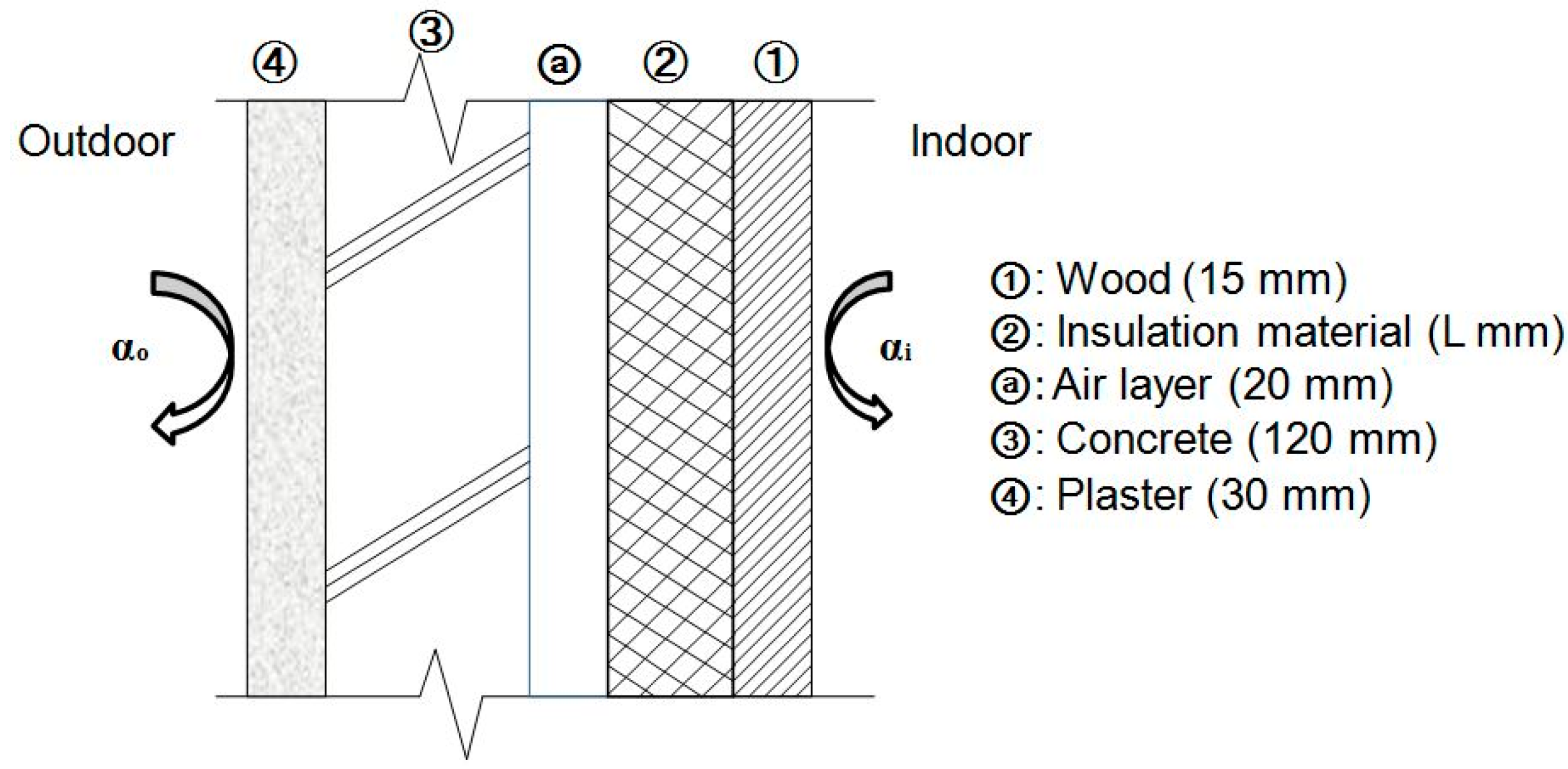
This study considered a homogeneous multi-layer building external wall structure that is widely used in Japan [13], and is illustrated in Figure 1. The multi-layer structure is composed of, in order from indoor to outdoor: 15 mm of wood, L mm of insulation material (expanded polystyrene (EPS) or glass wool or wood cement board), a 20-mm air layer, 120 mm of concrete, and 30 mm of plaster. The thermophysical properties of each material in the external wall structure are shown in Table 1. The thermophysical properties of the materials are those at a temperature of 20 °C.
2.2. External Wall Structure
For a homogeneous wall structure, the heat transfer through the thickness of wall structure can be expressed by Davies [14] based on Fourier’s law:
where ρ is the density of the material, [kg/m3]; Cp is the specific heat of the material, [J/kgK]; k is the thermal conductivity of the material, [W/mK]; T(x,t) is the temperature, [°C]; x is the distance coordinate that starts at zero from the external surface toward the internal surface, [m]; and t is the time, [s].
The temperature at the x-position of the wall and at time t, T(x,t) can be obtained using the method outlined by Davies [15]:
where Q is the heat flux from a unit external wall surface, [W/m2]; R is the thermal resistance of the wall, [m2K/W]; P is the time period, [s]; and j is the imaginary number, [-].
The temperature at the external wall surface (x = 0) and the heat flux at the external wall surface (x = 0) can be calculated using the following equations according to Urano and Uezono [16,17,18]:
where Text is the temperature at the external wall surface x = 0, [°C]; qext is the heat flux at the external wall surface x = 0, [W/m2]; l is the thickness of the wall material, [m]; Tint is the temperature at the internal wall surface x = l, [°C]; and qint is the heat flux at the internal wall surface x = l, [W/m2].
The above Equations (5)–(7) can be written as follows:
For a homogeneous multi-layer wall structure, Tint and qint can be represented by Equation (13):
where Rint and Rext are the internal wall surface resistance and external wall surface resistance, respectively, [m2K/W]; they are taken as 1/9 and 1/23, respectively in this study. Meanwhile, ai, bi, ci, and di are the elements of the wall layer-i matrix, and n is the number of wall layers.
The above Equation (13) can be represented by the following Equations (14) and (15):
where E11, E12, E21, and E22 are the elements of the multi-layer wall transmission matrix.
The thermal characteristics of external wall structures are dynamic and unsteady. This periodic change can be characterized by quantities such as thermal admittance and amplitude attenuation. These quantities were first introduced by Loudon based on a matrix analysis of periodic heat flow in solids [19]. This method is popularly known as the admittance method or the Chartered Institution of Building Services Engineering (CIBSE) method. The CIBSE (2006) method is used for estimating the unsteady heat transfer parameters of building envelopes.
The dynamic thermal characteristics of various external wall enclosures can be computed by the following relationships shown in Equations (16)–(22).
2.2.1. Thermal Transmittance (U)
The thermal transmittance of the wall structure and its thermal resistance (R) are a reciprocal relationship. The lower the thermal transmittance, the higher the thermal insulation of the external wall structure. The thermal transmittance can be calculated using Equation (16):
where U is the thermal transmittance of the wall structure, [W/m2K]; xi is the thickness of wall layer-i, [m]; ki is the thermal conductivity of wall layer-i, [W/mK]; and Rair is the thermal resistance of air layer [m2K/W], which is used instead of the corresponding xi/ki term.
2.2.2. Thermal Admittance (Y)
The thermal admittance of the wall structure is a measure of the thermal mass of the external surface material, and represents a surface’s ability to absorb heat from the atmosphere and release it back to the same over a given time period. It can be calculated using Equation (17):
where Y is the thermal admittance of the wall structure, [W/m2K]; E11 and E12 are calculated using the above Equation (15).
2.2.3. Time LAG (φ)
The time lag is the time that it takes for a heat flow from the outer surface of the wall to reach the inner surface. It is also called “decrement delay”. It can be calculated with Equation (18):
where φ is the time lag, [h]. For a thin wall structure with lower thermal capacity, its φ is close to zero.
2.2.4. Time Lead for Thermal Admittance (ω)
The time lead for thermal admittance is a measure of the time difference between the time of peak heat flow at the internal wall surface and the peak temperature of the internal wall surface. It can be derived by Equation (19):
where ω is the time lead for thermal admittance, [h].
2.2.5. Decrement Factor or Amplitude Attenuation (δ)
The decrement factor of the wall structure is the difference between the outside and inside wall surface temperature swings; it is also called “amplitude attenuation”. It is known that the higher the thermal mass, the lower δ becomes. The decrement factor can be calculated using Equation (20):
where δ is the decrement factor or amplitude attenuation of the wall structure, [-].
2.2.6. Surface Factor (F)
The surface factor is the ratio of shortwave radiant heat flow re-admitted to the atmosphere from the external wall surface to the heat flow striking upon the external wall surface. It can be calculated using Equation (21):
where F is the surface factor, [-].
2.2.7. Thermal Capacity (η)
The thermal capacity is the amount of heat stored within the wall surface per unit area of building element per unit degree of atmospheric temperature swing. This heat stored in the wall surface is released to the atmosphere when the outside temperature falls during the nighttime. It can be calculated using Equation (22):
where η is the thermal capacity, [J/m2K]; and t is the time period, [s].
3. Results and Discussion
In order to evaluate the impact of insulation type and thickness on the dynamic thermal characteristics of the external wall structure, seven thermal characteristics, including thermal transmittance (U), decrement factor (δ), time lag (φ), thermal admittance (Y), time lead for admittance (ω), surface factor (F), and thermal capacity (η) were evaluated by the above numerical methods, while using one of three types of insulation material (EPS, glass wool, and wood cement board) and varying the insulation thickness of the external wall structure from 0 m to 0.2 m with a thickness interval of 0.01 m, under the MATrix LABoratory (MATLAB) environment. The MATLAB codes for calculating the seven thermal characteristics are shown in Appendix A and Appendix B.
3.1. Impact on Thermal Transmittance (U)
Figure 2 shows the impact of insulation type and thickness on the thermal transmittance (U) of the external wall structure. It was found that the thermal transmittance decreased for all three types of insulation material, as insulation thickness was increased from 0 m to 0.2 m. If EPS was used as the insulation material in the wall structure, the thermal transmittance of the external wall structure decreased by 0.67 W/m2K (81.7%); it also decreased by 0.63 W/m2K (76.4%) if glass wool was used, and decreased by 0.42 W/m2K (50.8%) if wood cement board was used, while increasing the insulation thickness from 0 m to 0.2 m. As the insulation thickness increases from 0 m to 0.08 m, the thermal transmittance of the external wall structure decreased more sharply when the EPS and glass wool were used as insulation materials, compared with the condition where the wood cement board was used as insulation material. As the insulation thickness increases from 0.08 m to 0.2 m, there was a slight decrease of the thermal transmittance for the three types of insulation materials, which showed a decrease of 0.15 W/m2K (49.0%) for EPS, a decrease of 0.16 W/m2K (45.9%) for glass wool, and a decrease of 0.18 W/m2K (30.5%) for wood cement board.
The result indicates that the impact of insulation thickness on the thermal transmittance of an external wall structure is different owing to the different types of the insulation materials. In addition, it was found that there is a critical thickness for the thermal insulation of the external wall structure, and there is a trend of diminishing returns as more insulation is used above this critical thickness. This has been verified in previous research [20,21].
3.2. Impact on Decrement Factor or Amplitude Attenuation (δ)
Figure 3 shows the impact of insulation type and thickness on the decrement factor or amplitude attenuation (δ) of the external wall structure. It was found that the decrement factor of the external wall structure decreased for all of the three types of insulation materials, as insulation thickness increased from 0 m to 0.2 m. If EPS was used as an insulation material in the wall structure, the decrement factor of the external wall structure decreased by 4.45 × 10⁻⁴ (93.8%); it decreased by 3.14 × 10⁻⁴ (66.2%) if glass wool was used, and it decreased by 4.74 × 10⁻⁴ (about 100%) if wood cement board was used, while increasing the insulation thickness from 0 m to 0.2 m. Among the three types of insulation materials, the wood cement board had the sharpest decrease in decrement factor (as the insulation thickness increased to 0.06 m, the decrement factor fell to nearly 0), followed by EPS. The glass wool had the smallest decrease in decrement factor.
The result indicates that the decrement factor of the wall structure could possibly be reduced by increasing the insulation thickness of the wall. The degree of decrease in the decrement factor varied depending on the different types of insulation material. However, whether it is positive or negative effect depends on the insulation material type and the setting position of insulation in the wall structure (i.e., internal thermal insulation, external thermal insulation, middle thermal insulation) [5].
3.3. Impact on Time Lag (φ)
Figure 4 shows the impact of insulation type and thickness on the time lag (φ) of external wall structures. It was found that the change trend of the time lag for external wall structures with different types of insulation materials were different while increasing insulation thickness from 0 m to 0.2 m. The change period of the time lag with increasing insulation thickness for the wood cement board was the shortest (0.04 m per change period), followed by EPS (0.15 m per change period). The glass wool had the longest change period of time lag (0.16 m per half-change period).
The result shows that there is a change period of time lag with as the insulation thickness increases, and it differs for different types of insulation materials. In addition, it is found that the insulation types and thickness of the external wall structure strongly affect the time lag of the wall structure. Thus, an appropriate selection of insulation types and thickness becomes more important in terms of energy saving in buildings.
3.4. Impact on Thermal Admittance (Y)
Figure 5 shows the impact of insulation type and thickness on the thermal admittance (Y) of the external wall structure. It was found that there was almost no significant change in the thermal admittance for any of the three types of insulation materials, holding at around 18.4 W/m2K, while increasing insulation thickness from 0 m to 0.2 m.
Thus, it can be considered that the insulation type and thickness will yield no significant change in the thermal admittance to the external wall structure.
3.5. Impact on Time Lead for Admittance (ω)
Figure 6 shows the impact of insulation type and thickness on the time lead for admittance (ω) of the external wall structure. It was found that there was almost no significant change in the time lead for admittance for all three types of insulation materials, holding at around 2.45 h, while increasing insulation thickness from 0 m to 0.2 m.
Thus, it is considered that the insulation types and thickness will yield no significant change in the time lead for admittance to the external wall structure.
3.6. Impact on Surface Factor (F)
Figure 7 shows the impact of insulation type and thickness on the surface factor (F) of the external wall structure. It was found that there was almost no significant change in the surface factor (F) for all three types of insulation materials, holding at around 1.38, while increasing insulation thickness from 0 m to 0.2 m.
Thus, it is considered that the insulation type and thickness will yield no significant change in the surface factor to the external wall structure.
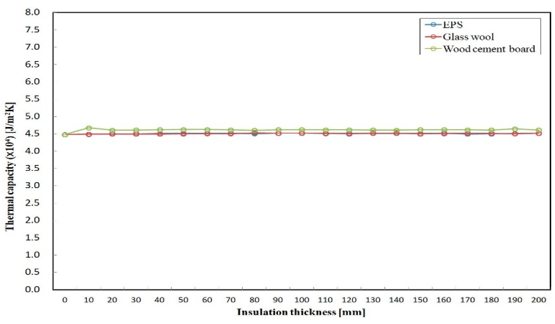
3.7. Impact on Thermal Capacity (η)
Figure 8 shows the impact of insulation type and thickness on the thermal capacity (η) of the external wall structure. It was found that there was almost no significant difference in the thermal capacity for EPS and glass wool, holding at around 4.5 × 10⁴ J/m2K, while increasing insulation thickness from 0 m to 0.2 m. As the insulation thickness increased from 0 m to 0.2 m, the thermal capacity for wood cement board also had almost no significant change, holding at around 4.6 × 10⁴ J/m2K, which is higher than that of EPS and glass wool. This is because both the thermal conductivity and density of the wood cement board were larger than for EPS and glass wool.
Thus, it is indicated that the insulation type and thickness will yield no significant change in the thermal capacity to the external wall structure, since the thermophysical properties (i.e., thermal conductivity and density) are far different from that of the other materials (i.e., concrete, plaster, steel) in the external wall structure.
4. Conclusions
In order to find the impact of insulation type and thickness on the dynamic thermal characteristics of the external wall structure, a homogeneous multi-layer building external wall structure widely used in Japan was selected, and seven thermal characteristics of the external wall, including U, δ, φ, Y, ω, F, and η, were investigated by changing the insulation thickness (from 0 m to 0.2 m) and varying the type of insulation material (EPS, glass wool, and wood cement board). The knowledge obtained is as follows:
- The U of the external wall structure varies depending on the different insulation type and thickness of the external wall structure. It was found that there is a critical thickness for the thermal insulation of the external wall structure, and the effect of thermal insulation will not be obvious when the thickness exceeds the critical value.
- The δ of the wall structure could possibly be reduced by increasing the insulation thickness of the wall. The degree of decrease in the decrement factor varies depending on the different type of insulation material.
- There is a change period of φ with the increasing insulation thickness, and it differs for different types of insulation material. The insulation type and thickness in the external wall structure strongly affects the φ of the wall structure.
- The insulation type and thickness will yield no significant change in the Y, ω, F, and η thermal characteristics of the external wall structure.
Future research will be focused on evaluating the impact of the dynamic thermal characteristics of more insulation types and different positions in more external wall structures.
Funding
This research received no external funding.
Acknowledgments
The author is very grateful to Emura and Farnham of Osaka City University for their supports.
Conflicts of Interest
The author declares no conflict of interest.
Appendix A
The first step for solving the matrix X = [E11 E12; E21 E22].
| clear; | ||
| P=3600; | % Time periods [s] | |
| pi=3.1415926; | ||
| drt=5.67*10-8; | % Stefan-Boltzmann constant | |
| j=sqrt(-1); | % Imaginary number | |
| Fe=0.9; | % Emissivity factor of wall surface which is equal to K*e [K=1; e=0.9] | |
| Tsi=15+273.15; | % Internal surface absolute temperature [K] | |
| Tso=15+273.15; | % External surface absolute temperature [K] | |
| hi=9.; | % For internal wall surface convective heat transfer coefficient [W/m2K] | |
| ho=23.; | % For external wall surface convective heat transfer coefficient [W/m2K] | |
| Rsint=1/hi; | % Internal surface resistance [m2K/W] | |
| Rsext=1/ho; | % External surface resistance [m2K/W] | |
| % Themophysical properties of building wall enclosure materials (from indoor to outdoor) | ||
| kw=0.179; | % Thermal conductivity of wood [W/mK] | |
| Dw=530; | % Density of wood [kg/m3] | |
| Cw=2300; | % Specific heat of wood [J/kgK] | |
| xw=0.015; | % Thickness of wood [m] | |
| ke=0.16; | % Thermal conductivity of Wood cement board [W/mK] | |
| De=680; | % Density of Wood cement board [kg/m3] | |
| Ce=1675; | % Specific heat of Wood cement board [J/kgK] | |
| xe=0.06; | % Thickness of Wood cement board [m] | |
| ka=0.026; | % Thermal conductivity of air layer [W/mK] | |
| Da=1.2; | % Density of air layer [kg/m3] | |
| Ca=1006; | % Specific heat of air layer [J/kgK] | |
| xa=0.02; | % Thickness of air layer [m] | |
| kc=0.9; | % Thermal conductivity of concrete [W/mK] | |
| Dc=2000; | % Density of concrete [kg/m3] | |
| Cc=879; | % Specific heat of concrete [J/kgK] | |
| xc=0.12; | % Thickness of concrete [m] | |
| kp=0.43; | % Thermal conductivity of plaster [W/mK] | |
| Dp=1250; | % Density of plaster [kg/m3] | |
| Cp=1050; | % Specific heat of plaster [J/kgK] | |
| xp=0.03; | % Thickness of plaster [m] | |
| % The homogeneous wall enclosure transmission matrix coefficients | ||
| % For wood material | ||
| uw=sqrt(pi*Dw*Cw*xw*xw/(kw*P)); | ||
| aw=sqrt(j*2*pi*kw*Dw*Cw/P); | ||
| Awo=cosh(uw)*cos(uw); | ||
| Awt=sinh(uw)*sin(uw); | ||
| Aws=(cosh(uw)*sin(uw)+sinh(uw)*cos(uw))/sqrt(2); | ||
| Awf=(cosh(uw)*sin(uw)-sinh(uw)*cos(uw))/sqrt(2); | ||
| % For Wood cement board material | ||
| ue=sqrt(pi*De*Ce*xe*xe/(ke*P)); | ||
| ae=sqrt(j*2*pi*ke*De*Ce/P); | ||
| Aeo=cosh(ue)*cos(ue); | ||
| Aet=sinh(ue)*sin(ue); | ||
| Aes=(cosh(ue)*sin(ue)+sinh(ue)*cos(ue))/sqrt(2); | ||
| Aef=(cosh(ue)*sin(ue)-sinh(ue)*cos(ue))/sqrt(2); | ||
| % For air layer | ||
| ua=sqrt(pi*Da*Ca*xa*xa/(ka*P)); | ||
| aa=sqrt(j*2*pi*ka*Da*Ca/P); | ||
| Aao=cosh(ua)*cos(ua); | ||
| Aat=sinh(ua)*sin(ua); | ||
| Aas=(cosh(ua)*sin(ua)+sinh(ua)*cos(ua))/sqrt(2); | ||
| Aaf=(cosh(ua)*sin(ua)-sinh(ua)*cos(ua))/sqrt(2); | ||
| % For concrete material | ||
| uc=sqrt(pi*Dc*Cc*xc*xc/(kc*P)); | ||
| ac=sqrt(j*2*pi*kc*Dc*Cc/P); | ||
| Aco=cosh(uc)*cos(uc); | ||
| Act=sinh(uc)*sin(uc); | ||
| Acs=(cosh(uc)*sin(uc)+sinh(uc)*cos(uc))/sqrt(2); | ||
| Acf=(cosh(uc)*sin(uc)-sinh(uc)*cos(uc))/sqrt(2); | ||
| % For plaster material | ||
| up=sqrt(pi*Dp*Cp*xp*xp/(kp*P)); | ||
| ap=sqrt(j*2*pi*kp*Dp*Cp/P); | ||
| Apo=cosh(up)*cos(up); | ||
| Apt=sinh(up)*sin(up); | ||
| Aps=(cosh(up)*sin(up)+sinh(up)*cos(up))/sqrt(2); | ||
| Apf=(cosh(up)*sin(up)-sinh(up)*cos(up))/sqrt(2); | ||
| % Solve matrix X=[E11 E12; E21 E22] | ||
| A=[1 -Rsint; 0 1]; | % For internal layer | |
| B=[Awo+Awt*j (Aws+Awf*j)/aw; (-Awf+Aws*j)*aw Awo+Awt*j]; | % For 1st wood layer | |
| C=[Aeo+Aet*j (Aes+Aef*j)/ae; (-Aef+Aes*j)*ae Aeo+Aet*j]; | % For 2nd Wood cement board layer | |
| D=[Aao+Aat*j (Aas+Aaf*j)/aa; (-Aaf+Aas*j)*aa Aao+Aat*j]; | % For 3th air layer | |
| E=[Aco+Act*j (Acs+Acf*j)/ac; (-Acf+Acs*j)*ac Aco+Act*j]; | % For 4rd concrete layer | |
| F=[Apo+Apt*j (Aps+Apf*j)/ap; (-Apf+Aps*j)*ap Apo+Apt*j]; | % For 5th plaster layer | |
| G=[1 -Rsext; 0 1]; | % For external layer | |
| X=A*B*C*D*E*F*G | ||
| ------ | ||
Appendix B
The second step for calculating different thermal characteristics of external wall structure using the matrix value obtained in Appendix A.
| clear; | ||
| drt=5.67*10-8; | % Stefan-Boltzmann constant | |
| pi=3.1415926; | ||
| i=sqrt(-1); | ||
| hi=9.; | % For internal wall surface convective heat transfer coefficient [W/m2K] | |
| ho=23.; | % For external wall surface convective heat transfer coefficient [W/m2K] | |
| Rsint=1/hi; | % Internal surface resistance [m2K/W] | |
| Rsext=1/ho; | % External surface resistance [m2K/W] | |
| % Themophysical properties of building wall enclosure materials (from indoor to outdoor) | ||
| kw=0.179; | % Thermal conductivity of wood [W/mK] | |
| Dw=530; | % Density of wood [kg/m3] | |
| Cw=2300; | % Specific heat of wood [J/kgK] | |
| xw=0.015; | % Thickness of wood [m] | |
| ke=0.16; | % Thermal conductivity of Wood cement board [W/mK] | |
| De=680; | % Density of Wood cement board [kg/m3] | |
| Ce=1675; | % Specific heat of Wood cement board [J/kgK] | |
| xe=0.06; | % Thickness of Wood cement board [m] | |
| ka=0.026; | % Thermal conductivity of air layer [W/mK] | |
| Da=1.2; | % Density of air layer [kg/m3] | |
| Ca=1006; | % Specific heat of air layer [J/kgK] | |
| xa=0.02; | % Thickness of air layer [m] | |
| kc=0.9; | % Thermal conductivity of concrete [W/mK] | |
| Dc=2000; | % Density of concrete [kg/m3] | |
| Cc=879; | % Specific heat of concrete [J/kgK] | |
| xc=0.12; | % Thickness of concrete [m] | |
| kp=0.43; | % Thermal conductivity of plaster [W/mK] | |
| Dp=1250; | % Density of plaster [kg/m3] | |
| Cp=1050; | % Specific heat of plaster [J/kgK] | |
| xp=0.03; | % Thickness of plaster [m] | |
| E11= 1.0e+07 *(0.3913 − 0.2623i); | ||
| E12= 1.0e+07 *(-0.0255 − 0.0014i); | ||
| E21= 1.0e+07 *(-2.0146 + 3.2741i); | ||
| E22= 1.0e+07 *(0.1943 − 0.0766i); | ||
| % Thermal transmittance (U) [W/m2K] | ||
| U=1/(Rsext+(xw/kw)+(xe/ke)+(xa/ka)+(xc/kc)+(xp/kp)+Rsint) | ||
| % Decrement factor or attenuation factor or amplitude attenuation (d) [-] | ||
| d=abs(-1/(U*E12)) | ||
| % Decrement delay or time lag or phase shift (tlag) [h] | ||
| tlag=(12/pi)*atan(imag(-1/(U*E12))/real(-1/(U*E12))) | ||
| % Thermal admittance (Y) [W/m2K] | ||
| Y=abs(-E11/E12) | ||
| % Time lead for thermal admittance (w) [h] | ||
| w=(12/pi)*atan(imag(-E11/E12)/real(-E11/E12)) | ||
| % Surface factor (F) [-] | ||
| F=abs(1-Rsint*(-E11/E12)) | ||
| % Associated time delay of surface factor (stlag) [h] | ||
| stlag=(12/pi)*atan(imag(1-Rsint*(-E11/E12))/real(1-Rsint*(-E11/E12))) | ||
| % Thermal heat capcity (Cap) [J/m2K] | ||
| T=3600; | % Times [s] | |
| Cap=(T/2*pi)*abs((E22-1)/E12) | ||
References
- Kesik, T.J. Building Enclosure Design Principles and Strategies. Ph.D. Thesis, University of Toronto, Toronto, ON, Canada, 8 August 2016. [Google Scholar]
- Duffin, R.J.; Knowles, G. A passive wall design to minimize building temperature swings. Sol. Energy 1984, 33, 337–342. [Google Scholar] [CrossRef]
- Knowles, T.R. Proportioning composites for efficient thermal storage walls. Sol. Energy 1983, 31, 319–326. [Google Scholar] [CrossRef]
- Asan, H. Investigation of wall’s optimum insulation position from maximum time lag and minimum decrement factor point of view. Energy Build. 2000, 32, 197–203. [Google Scholar] [CrossRef]
- Asan, H. Effects of Wall’s insulation thickness and position on time lag and decrement factor. Energy Build. 1998, 28, 299–305. [Google Scholar] [CrossRef]
- Evola, G.; Marletta, L. A dynamic parameter to describe the thermal response of buildings to radiant heat gains. Energy Build. 2013, 65, 448–457. [Google Scholar] [CrossRef]
- Kontoleon, K.J.; Eumorfopoulou, E.A. The influence of wall orientation and exterior surface solar absorptivity on time lag and decrement factor in the Greek region. Renew. Energy 2008, 33, 1652–1664. [Google Scholar] [CrossRef]
- Liu, M.; Wittchen, K.B.; Heiselberg, P.K.; Winther, F.V. Development and sensitivity study of a simplified and dynamic method for double glazing facade and verified by a full-scale façade element. Energy Build. 2014, 68, 432–443. [Google Scholar] [CrossRef]
- International Standard ISO 13786. Thermal Performance of Building Components—Dynamic Thermal Characteristics—Calculation Methods, 2nd ed.; International Organization for Standardization: Geneva, Switzerland, 2007. [Google Scholar]
- JIS R 3106 (2017): Test Method for Transmittance, Reflectance, Emissivity and Solar Heat Gain of Flat Glasses. Available online: http://www.jisc.go.jp/app/jis/general/GnrJISSearch.html (accessed on 1 August 2018). (In Japanese)
- JIS R 3107 (2017): Method for Calculating Thermal Resistance of Sheet Glasses and Heat Transmission Coefficient in Construction. Available online: http://www.jisc.go.jp/app/jis/general/GnrJISSearch.html (accessed on 1 August 2018). (In Japanese)
- JIS A 1412-2 (2016): Method for Measuring Thermal Resistance and Thermal Conductivity of Thermal Insulation Material—Part 2: Heat Flow Meter Method (HFM Method). Available online: http://www.jisc.go.jp/app/jis/general/GnrJISSearch.html (accessed on 1 August 2018). (In Japanese)
- Tanaka, J.; Takeda, H.; Adachi, T.; Tsuchiya, T. Latest Building Environmental Engineering (Revision II); Inoue Shoin Co., Ltd.: Tokyo, Japan, 2001; pp. 191–192. (In Japanese) [Google Scholar]
- Davies, T.W. Thermodynamics, Heat & Mass Transfer, and Fluids Engineering, Fourier’s Law. Thermopedia 2011. [Google Scholar] [CrossRef]
- Davies, M.G. Building Heat Transfer; John-Wiley & Sons Ltd.: Chichester, UK, 2004. [Google Scholar]
- Urano, Y.; Watanabe, T. An analysis of multi-layer wall heat transfer by state transition matrix: Part 1 An approximate transfer functions model and its accuracy. Trans. Archit. Inst. Jpn. 1981, 305, 97–111. (In Japanese) [Google Scholar] [CrossRef]
- Urano, Y.; Watanabe, T. An analysis of multi-layer wall heat transfer by state transition matrix: Part 2 A successive calculation method and its accuracy. Trans. Archit. Inst. Jpn. 1982, 311, 57–66. (In Japanese) [Google Scholar] [CrossRef]
- Uezono, M. Present situation of Measuring method for Thermal properties of Building materials. Netsu Bussei 1992, 6, 23–28. (In Japanese) [Google Scholar] [CrossRef]
- Chartered Institution of Building Services Engineers (CIBSE). Environmental Design CIBSE Guide-A, 7th ed.; CIBSE: London, UK, 2006. [Google Scholar]
- Yuan, J.; Emura, K.; Sakai, H. Field measurement of the reflectance of highly reflective roofing sheets installed in school buildings. Soc. Heat. Air-Condi. Sanit. Eng. Jpn. 2012, 180, 23–30. (In Japanese) [Google Scholar]
- Yuan, J.; Farnham, C.; Emura, K.; Alam, M.A. Proposal for optimum combination of reflectivity and insulation thickness of building external walls for annual thermal load in Japan. Build. Environ. 2016, 103, 228–237. [Google Scholar] [CrossRef]
Figure 1.
Cross-sectional view of the external wall structure.

Figure 2.
Impact of insulation type and thickness on the thermal transmittance of the external wall structure.
Figure 2.
Impact of insulation type and thickness on the thermal transmittance of the external wall structure.
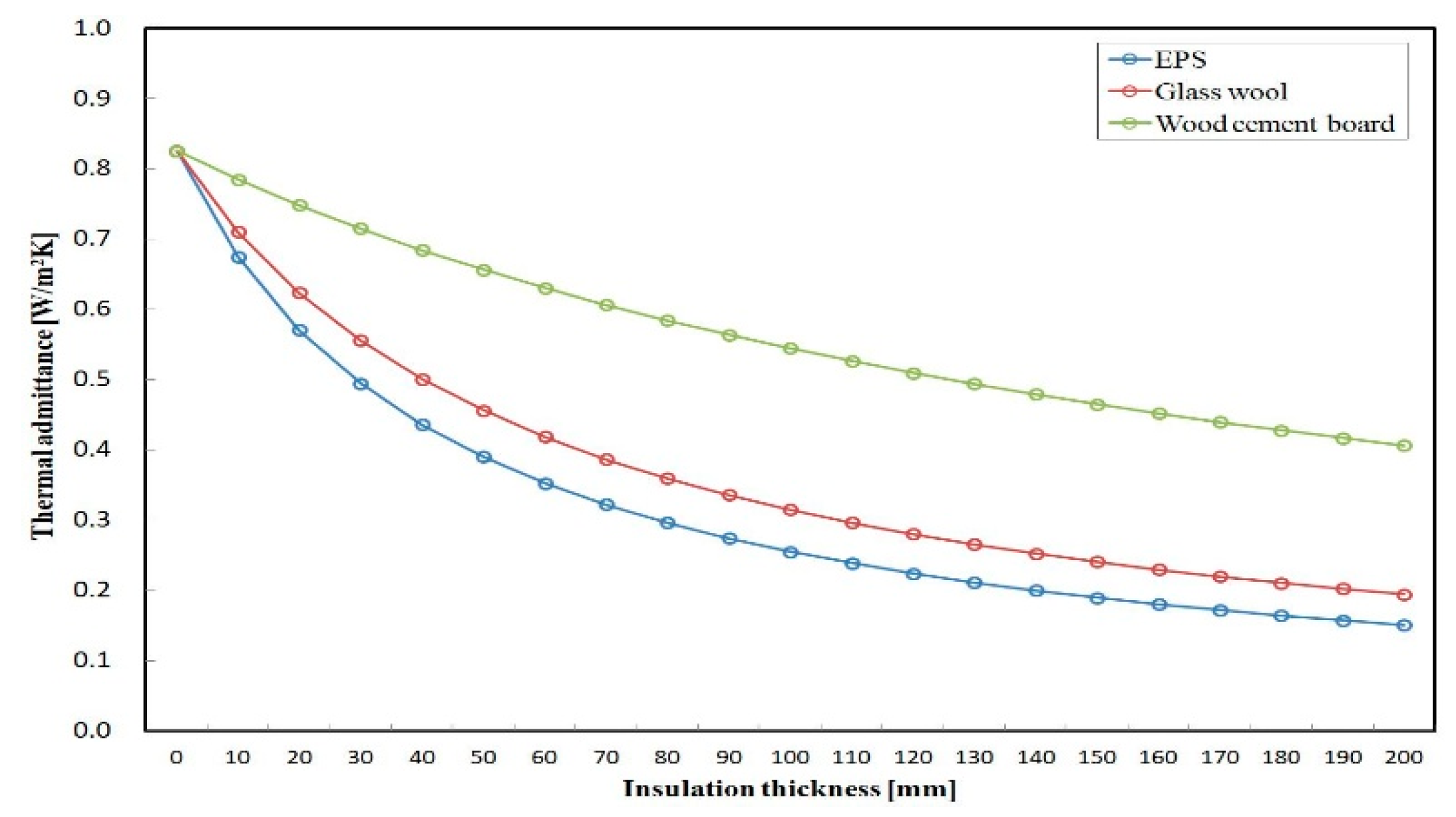
Figure 3.
Impact of insulation type and thickness on the decrement factor or amplitude attenuation of the external wall structure.
Figure 3.
Impact of insulation type and thickness on the decrement factor or amplitude attenuation of the external wall structure.
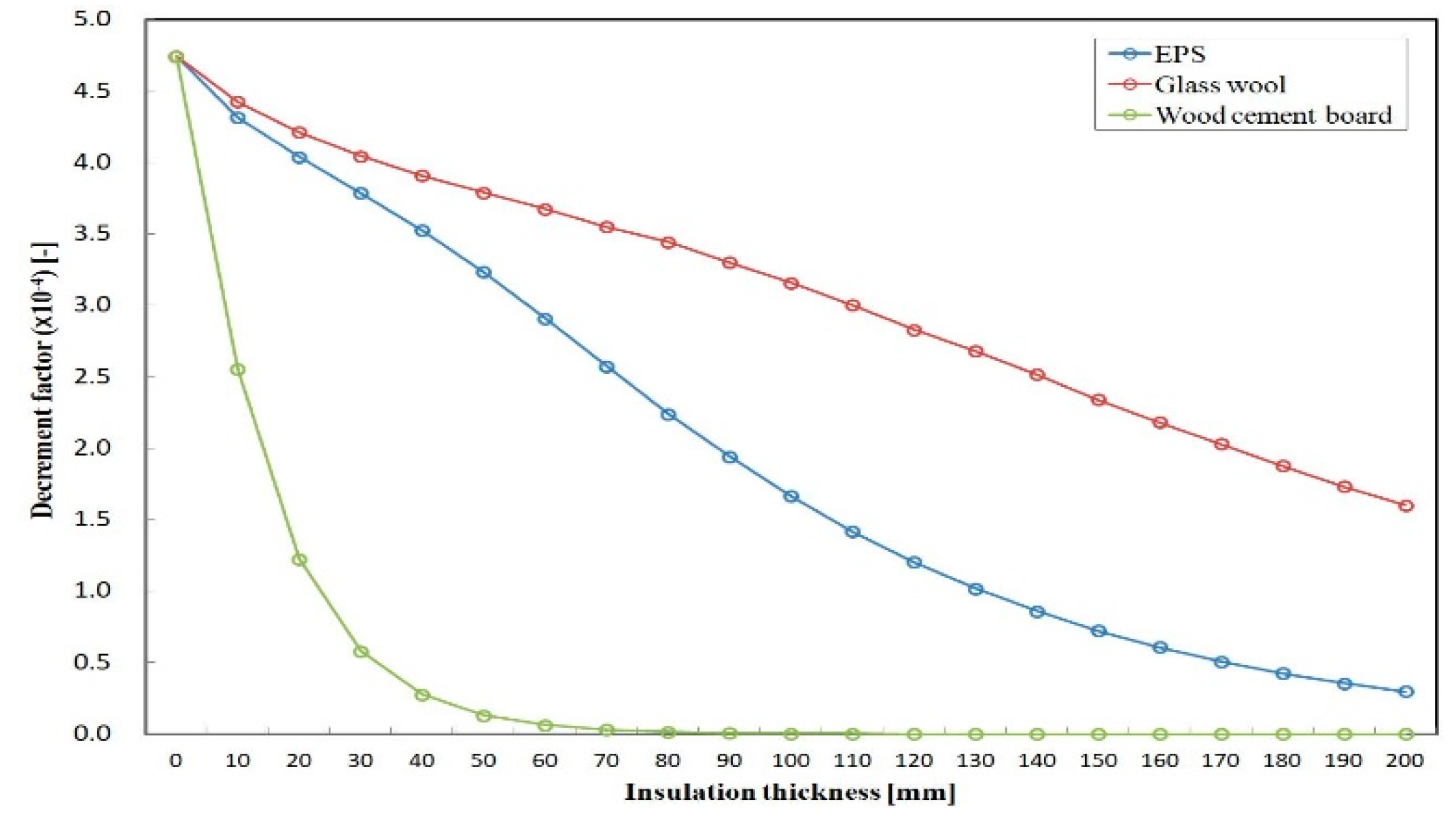
Figure 4.
Impact of insulation type and thickness on the time lag of the external wall structure.
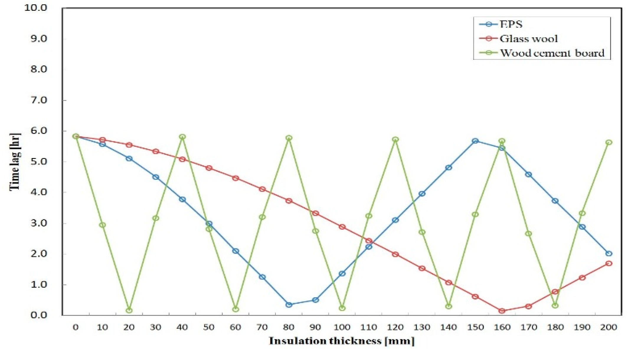
Figure 5.
Impact of insulation type and thickness on the thermal admittance of the external wall structure.
Figure 5.
Impact of insulation type and thickness on the thermal admittance of the external wall structure.
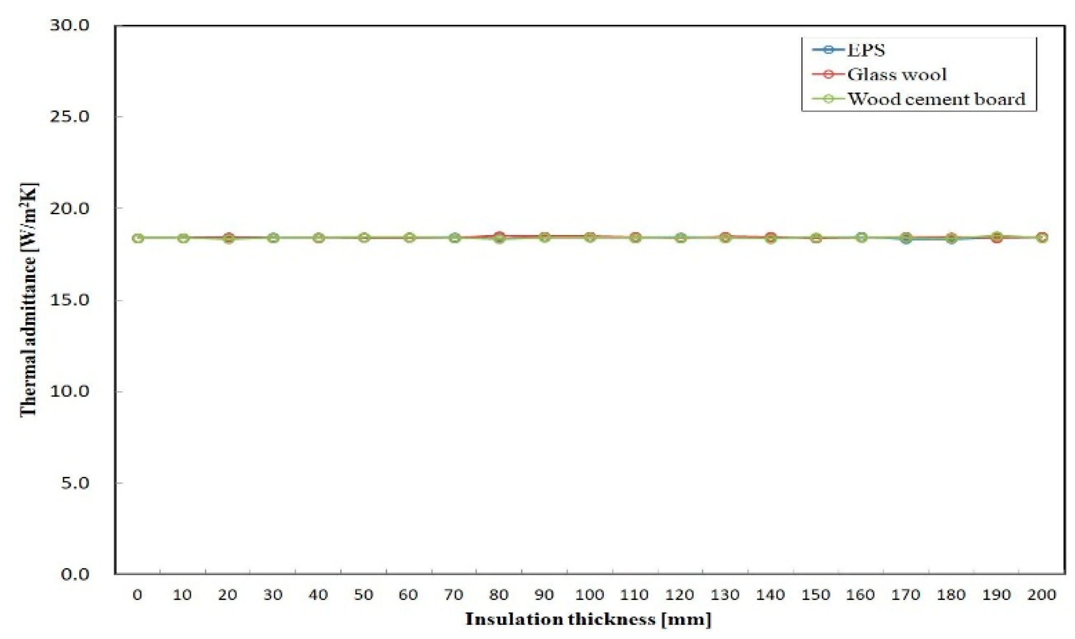
Figure 6.
Impact of insulation type and thickness on the time lead for thermal admittance of the external wall structure.
Figure 6.
Impact of insulation type and thickness on the time lead for thermal admittance of the external wall structure.
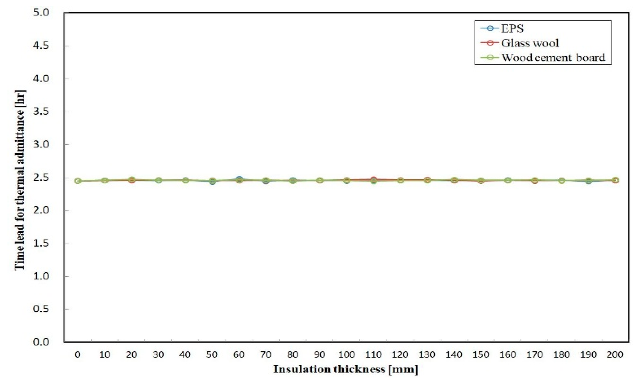
Figure 7.
Impact of insulation type and thickness on the surface factor of the external wall structure.
Figure 7.
Impact of insulation type and thickness on the surface factor of the external wall structure.
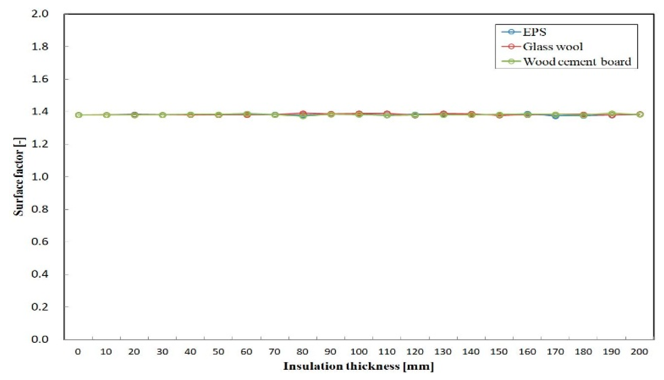
Figure 8.
Impact of insulation type and thickness on the thermal capacity of the external wall structure.
Figure 8.
Impact of insulation type and thickness on the thermal capacity of the external wall structure.

Table 1.
Thermophysical properties of building materials at a temperature of 20 °C.
| Building Material | Thermal Conductivity (k) [W/mK] | Density (ρ) [kg/m3] | Specific Heat (Cp) [J/kgK] |
|---|---|---|---|
| Wood | 0.179 | 530 | 2300 |
| Expanded polystyrene | 0.037 | 16 | 1340 |
| Glass wool | 0.051 | 10 | 837 |
| Wood cement board | 0.16 | 680 | 1675 |
| Air layer | 0.026 | 1.2 | 1006 |
| Concrete | 0.9 | 2000 | 879 |
| Plaster | 0.43 | 1250 | 1050 |
© 2018 by the author. Licensee MDPI, Basel, Switzerland. This article is an open access article distributed under the terms and conditions of the Creative Commons Attribution (CC BY) license (http://creativecommons.org/licenses/by/4.0/).
Share and Cite
MDPI and ACS Style
Yuan, J. Impact of Insulation Type and Thickness on the Dynamic Thermal Characteristics of an External Wall Structure. Sustainability 2018, 10, 2835. https://doi.org/10.3390/su10082835
AMA Style
Yuan J. Impact of Insulation Type and Thickness on the Dynamic Thermal Characteristics of an External Wall Structure. Sustainability. 2018; 10(8):2835. https://doi.org/10.3390/su10082835
Chicago/Turabian StyleYuan, Jihui. 2018. "Impact of Insulation Type and Thickness on the Dynamic Thermal Characteristics of an External Wall Structure" Sustainability 10, no. 8: 2835. https://doi.org/10.3390/su10082835
Note that from the first issue of 2016, this journal uses article numbers instead of page numbers. See further details here.