Merging Vehicles and Lane Speed-Flow Relationship in a Work Zone


1
School of Electrical & Control Engineering, Chang’an University, Nan Er Huan Zhong Duan, Xi’an 710064, Shaanxi, China
2
School of Transportation & Logistics, Dalian University of Technology, No. 2 Linggong Road, Dalian 116024, Liaoning, China
*
Author to whom correspondence should be addressed.
Sustainability 2018, 10(7), 2210; https://doi.org/10.3390/su10072210
Submission received: 1 May 2018
/
Revised: 3 June 2018
/
Accepted: 15 June 2018
/
Published: 28 June 2018
(This article belongs to the Section Sustainable Transportation)
Abstract
:In addition to closed merge lanes as physical bottlenecks of work zones, traffic oscillations caused by merging vehicles at multiple locations could reduce work-zone capacity. This study took a step-wise procedure to reveal spatial distributions of merging vehicles along work zones and their influence on speed-flow relationships of lane traffic flows. Field data showed that inserting vehicles from merge lanes could spread their influence over adjacent unclosed through lanes. Moreover, with increases in total volume, merging vehicles could choose their inserting positions further upstream of the work zone, which could induce oscillations near the insertion point. At the identified upstream bottlenecks, capacity drop was found in speed-flow diagrams of through-lane traffic, but it was not found in the diagrams of merge-lane traffic flows. Lack of sufficient demand and special merging behaviors on merge lanes could be attributed to the distinct speed-flow relationship. Two-part piecewise regression models were developed to fit the speed-flow relationships of uncongested and congested flows of through lanes. By comparing the estimated speed-flow models, it was found that when a queue is forming, the extent of the capacity drop and speed reduction is different for through lanes. Queue discharge uses different lengths of time on through lanes and multiple merging locations.
1. Introduction
As transportation infrastructure ages, work zones are frequently established on highways for pavement rehabilitation and facility repair, causing traffic congestion in the work-zone segment. Accurate estimations of traffic conditions in the influential areas of work zones are important for highway agencies because this information directly relates to the design of configurations of work zones and the efficiency of traffic management. The roadway cross-section where the changes in geometric alignment result in capacity reduction, such as lane drop and roadway realignment with an angle [1,2], is often thought of as a physical bottleneck of the work zone. However, active bottlenecks caused by drivers’ merging behaviors occurring upstream of work zones could be another important cause of capacity reduction. Such a phenomenon observed at the on-ramp or off-ramp area of the freeway has been modelled in recent studies [3,4,5], but few studies have been concerned about how inserted vehicles affect work-zone traffic. This situation has been taken into account in the simulation model of Meng and Weng [6] but, until now, no empirical study focuses on it, at least to the best of the authors’ knowledge. To fill this gap, some basic characteristics of the merging behavior in work-zone areas must be understood, which will be briefly described below.
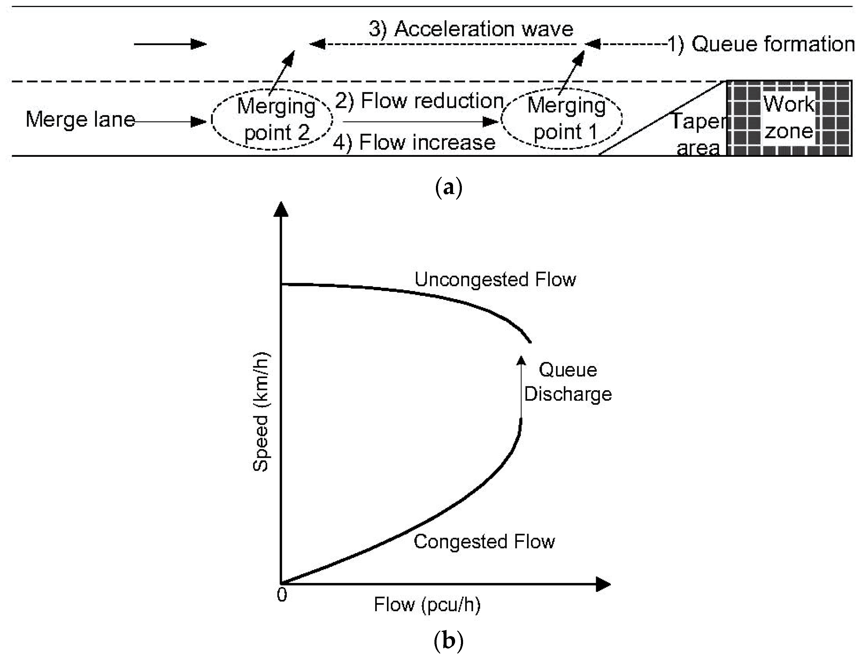
Temporal lane drop is commonly seen in a highway work zone. The vehicles running upstream of the closed lane (namely, the merge lane) have to merge with traffic on the unclosed lane (namely, the through lane) when they approach the work zone. Due to the temporary nature of construction work, drivers could receive the information about work zones in different ways, e.g., via a website, on-board radio, or roadside alarming sign. Compared with common merging circumstances they are familiar with, such as highway ramps and interchanges, drivers’ responses to lane drop at work zones could be uncertain. Some could follow the instructions of merging signs to conduct discretionary lane changes upstream of the lane drop site, while others might travel a longer distance to find preferred merging locations or even conduct mandatory lane changes near the work zone taper where they must do so. Several studies have found that the traffic oscillations arising at lane-drop sites derive from merging vehicles [7,8], and some numerical investigations have determined that the oscillatory patterns could be affected by travel demand, roadway geometry, merging frequency, and driver characteristics [9,10,11]. The uncertainty of drivers’ choices on merging locations upstream of lane-dropped sites, like work zones, could aggravate the influence of traffic oscillations on segment capacity. A reasonable interpretation proposed by Zhang and Shen could connect merging behaviors and traffic oscillations at the lane drop site [9]. The generation mechanism of the oscillations is shown in Figure 1a and can be summarized as follows: At first, since the lane drop site is a physical bottleneck of the segment, the vehicles on the merge lane inserting at merging point 1 close to the taper generate a queue on the through lane. Next, when such a queue spills back to the upstream location parallel to merging point 2, the merging onto the through lanes becomes harder because of the increased density on the through lanes. The drivers insisting on merging at this location must slow down to find acceptable inserting gaps nearby, thus blocking the vehicles that intend to merge at merging point 1. Thus, the merge-lane flow downstream of merging point 2 declines. Third, since fewer vehicles merge at point 1, more vehicles on the through lane are able to be discharged, which lowers the density of through-lane traffic and generates an acceleration wave traveling upstream along the through lane. Finally, when the acceleration wave reaches point 2, the density reduction of through-lane traffic there allows for more vehicles on the merge lane to insert. Hence, more vehicles intending to merge at point 1 can enter the downstream segment to accomplish implementing their intentions, which will launch a new round of oscillation.
The influence of the oscillations on the traffic at the lane drop site can be explicitly distinguished from the speed-flow diagram shown in Figure 1b, in which two-part piecewise curves are applied to fit the congested and uncongested flows, respectively. The traffic flow rate within bottleneck area shows a slight reduction when a queue forms upstream, namely the capacity drop, while a speed reduction line appears when the queue discharges. Multi-part piecewise curves, more commonly seen in empirical studies, usually result in better estimation accuracy [12,13,14]. However, in the authors’ view, with sufficient sample points, multiple piecewise curves would outperform their single- or two-piece counterparts on goodness of fit, but setting too many traffic regimes could weaken transferability of the estimated model. Inspired by the work of Zhang and Shen [9], some limitations are found in existing studies on work-zone traffic. First, the influence of oscillations shown in Figure 1a imposes on lane traffic, but most existing studies on work-zone traffic have depended on cross-section data, which could not capture the difference in the oscillations on different lanes. Some recent studies found that flow-density relationships of different lane traffic at the same cross-section could be distinguished from each other [15,16,17]. Hence, analysis of lane-based traffic data could provide deeper insights into the influence of merging vehicles on work-zone traffic. Second, only two merging points were set in the lane drop scenario illustrated in Figure 1a. In real traffic, merging vehicles could emerge at more locations upstream of the work zone, so their disturbances on through-lane traffic could be more frequent, making the oscillation patterns more complex. In this view, it is necessary to collect traffic data at various work-zone sites, rather than at single sites, as most studies are currently done. Third, the segment presented in Figure 1a can refer to the work zones with one- and two-lane closures. In the analysis of the work-zone segment traffic with more than two lanes, such as three- to one-lane closures or four- to two-lane closures, the influence of merging vehicles on all unclosed through-lane traffic should be taken into account. The abovementioned research gaps will be filled in this paper.
Field traffic data was applied to determine the influence of merging vehicles on lane speed-flow relationships of work zone traffic. As one of the fundamental diagrams, the speed-flow diagram is often used to evaluate work-zone traffic conditions at the macroscopic level [1,12,14,18,19], so it was also applied in the current study. Variance of lane utilizations at multiple locations was used to identify spatial distribution of merging behaviors along work zones. Based on this knowledge, the study sites where merging behaviors frequently occur can be identified, and traffic data collected at these sites were applied to model lane speed-flow relationships. The knowledge obtained from this paper is expected to be a reference for work-zone control plan design and control device deployment, such as dynamic merging control, speed limit signs, and deceleration rumble strips.
2. Study Site and Data Collection
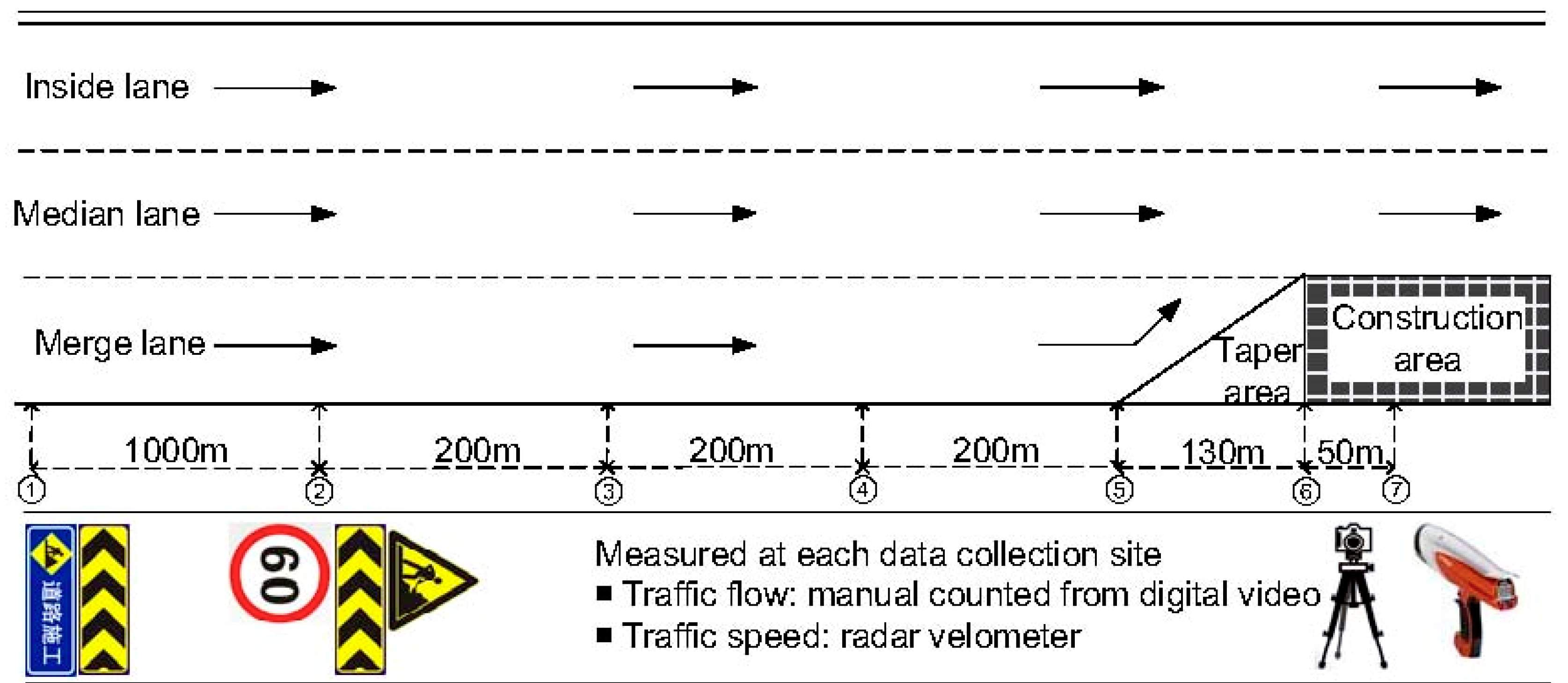
A work zone located on the G15 National Highway of China was chosen as the study case. This work zone was established for pavement rehabilitation in one driving direction. The cross-section of the work-zone segment consisted of one closed merge lane and two unclosed through lanes, as shown in Figure 2. To avoid misunderstanding, the through lane next to the merge lane is referred to the median lane, and the other through lane next to the median lane is the inside lane. Since the nearest ramp is more than 5 km away, the work zone traffic is assumed to be unaffected by the ramp bottleneck. A 130 m-long taper area designated by barricades was set upstream of the work-zone construction area. Lane traffic data was collected at seven sites, numbered as 1–7 in Figure 2, along the work zone from the upstream to the construction area. Site 5 is located at the start of the work zone taper. Site 6 and Site 7, respectively, are located at the start and inside of the construction area. Site 1 was set to record traffic conditions without the influence of the work zone. The traffic at other sites is deemed most likely to be affected by the work zone, owing to some traffic control signs placed at these sites, including “Work Zone Ahead”, “Work Zone”, “Left Detour”, and “Work Zone Speed Limit”. Traffic flow data was collected by digital video cameras for five hours from the non-peak hour to the peak hour. Lane traffic flow was deduced from these videos, and lane speed was collected by a radar velometer at each site. Flow on each lane is notated as , , or , while lane speed is noted as , , or . The data was aggregated every three minutes to ensure enough vehicles were included in one sample, as well as the fluctuation of traffic flow reflected by different samples. In flow counting, a medium truck was equivalently converted to two passenger cars, and a heavy truck was converted to three passenger cars.
3. Spatial Characteristics of Merging Behaviors
Instead of counting merging vehicles at each site, the spatial distribution of merging behaviors along the work zone is measured in this paper by inspecting lane flow distribution, which has been done in some studies [15,16,18]. Here, the proportion of each lane flow (, , or ) with respect to total cross-section flow () is calculated to reflect lane traffic distribution on a road cross-section. The proportion fluctuation in different time intervals can reflect the temporal variance of drivers’ lane choices. Since the flow data collected at all cross-sections was extracted from the videos recording in the same period, is approximately identical at each site. Hence, the variance of lane flow distribution at longitudinal successive sites can reflect the possibility of merging behavior appearing along the work zone.
3.1. Average Lane Flow Distribution
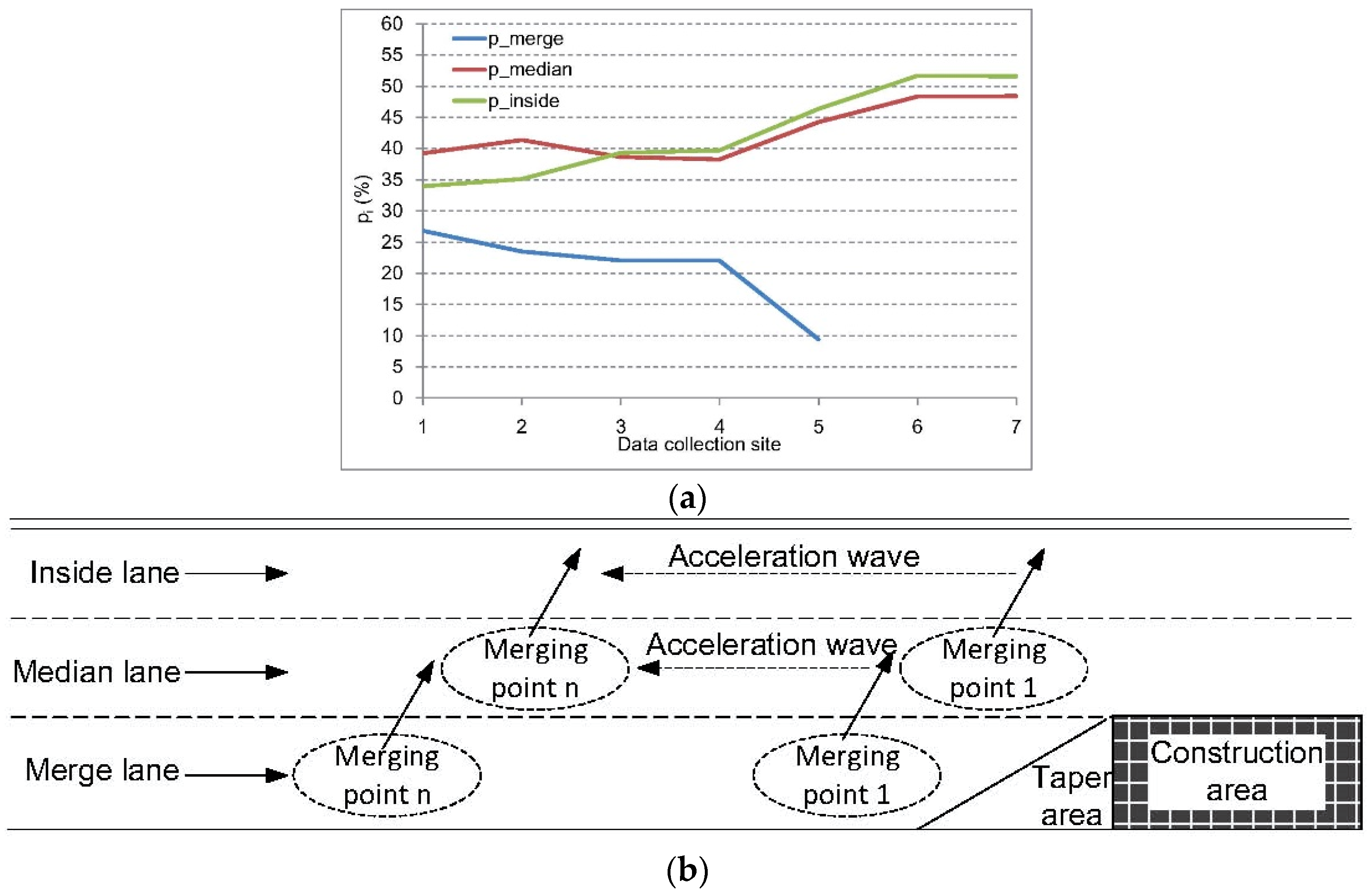
Average lane flow distribution of all samples collected at each site is listed in Table 1, and its fluctuation along different sites is illustrated in Figure 3a. Generally, at upstream segments of the work zone from Site 1 to Site 5, the median lane occupies the largest proportion of total cross-section flow on average ( = 40.35%), while the merge lane has the smallest proportion ( = 20.76%). Low utilization of the merge lane could be owing to a larger percentage of heavy vehicles running in it. In China, a heavy vehicle on the highway should run on the outside lane (here, the merge lane). Although the number of heavy vehicles was equivalent to passenger cars in flow counting, their lower speed could still make passenger car drivers reluctantly follow even without the influence of the work zone.
An obvious trend seen from Table 1 is that keeps declining from Site 1 to Site 5, so the merging signs set at the roadside are effective at least to some degree. Particularly, the largest decline of exists between Site 4 and Site 5 (from 22.02% to 9.41%), which means that many drivers choose to make lane changes within 200 m before work the zone taper. Another interesting finding is that declines slightly from Site 2 to Site 4, while at other sites it continues increasing. This decrease implies that, from Site 2 to Site 4, more vehicles switch from the median lane to the inside lane than the ones inserting to the median lane from the merge lane. The inserted vehicles from the merge lane to the median lane could induce vehicles originally travelling on the median lane to change to the inside lane, which causes a chain effect on the inside-lane traffic, as shown in Figure 3b. The heaviest chain effect appears between Site 4 and Site 5, where both and increase steeply. The larger increase of than indicates that the inside-lane traffic could even suffer more of an impact from merging vehicles than its median counterpart. After Site 6, lane flow distributions at Site 6 and Site 7 become stable, as well as become close to each other in value. Such phenomena mean that merging behaviors are seldom seen when vehicles enter the construction area of the work zone, and drivers do not especially prefer a particular lane in an aggregated view.
From the analysis above, it is recognized that merging behaviors could happen far upstream of the work zone. The vehicles inserted from the merge lane to the median lane could induce vehicles originally travelling in the median lane to switch to the inside lane. This chain effect could cause traffic oscillations at both the median lane and the inside lane, and reduce their capacities upstream of the work zone. Such an effect is also noted in recent research on capacity drop in highway ramp areas [20,21], claiming that the inside lanes contribute more than the outer ones to capacity drop multi-lane freeways. It is another reason for us to inspect the influence of merging vehicles on each lane of traffic at the work zone from a cross-section perspective.
3.2. Relationship of Lane Flow Proportion and Cross-Section Flow/Speed
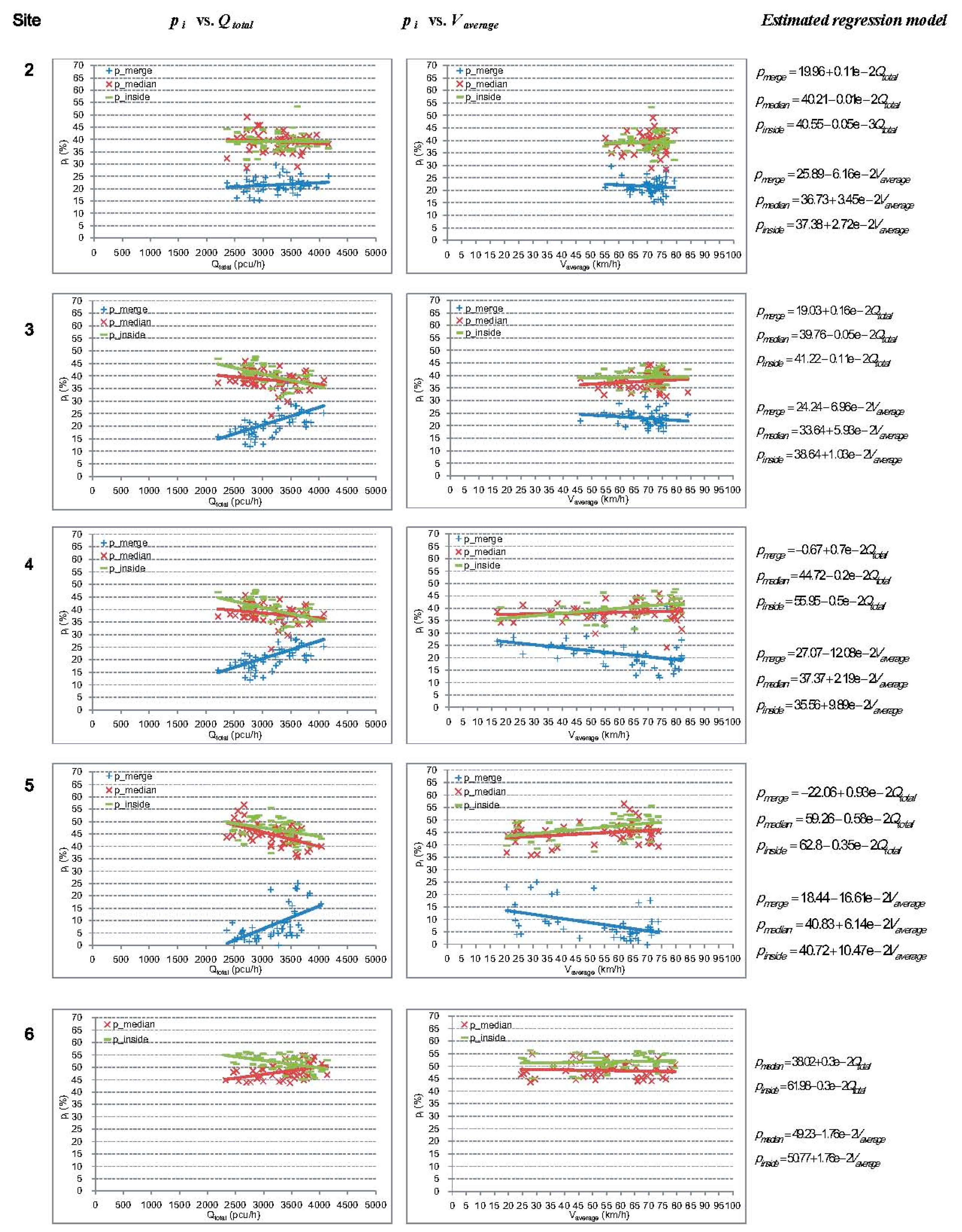
Based on the descriptive analysis above, the relationship between lane flow proportion and , as well as , will be detailed in this section. As shown in the last section, the variance of average lane traffic distribution between Site 1 and Site 2 is small considering their distance (1000 m), and lane flow distribution is stable from Site 6 to Site 7. Hence, Site 1 and Site 7 are excluded from the following analysis. The diagrams of with respect to and are listed in Figure 4, in which the samples of , , and are respectively colored as blue, red, and green. The relationship between lane flow distribution and traffic density is not analyzed in this section because flow and speed can be directly measured in the field, but density cannot. Density needs to be estimated using the space-mean speed, so its value is not as reliable as flow and speed. However, since traffic density is monotonic with instant speed, its relationship with the lane-flow proportion can still be inferred from with respect to From the diagrams in vs. column in Figure 4, it can be determined that ranges from 2000 pcu/h to 4500 pcu/h. An intuitive trend in the vs. column is that sample dispersion increases from Site 2 to Site 5, i.e., more low-speed samples appear at the sites closer to the work zone. This condition could be attributed to the 60 km/h speed limit sign set at Site 2. Although many vehicles were speeding, the speed limit sign is still workable to some degree. The samples shown in all diagrams of Figure 4 follow a linear trend. Hence, linear regressions models, as shown in Equation (1), are developed to fit this trend. The estimated regression models are also included in Figure 4.
3.2.1. Work Zone Upstream: Site 2 to Site 5
In the cross-section level, as increases, always increases, while and decrease (in Figure 4: > 0, < 0, < 0). Thus, an increase in cross-section flow causes more vehicles to stay in the merge lane while vehicles in the median lane and the inside lane correspondingly decrease. This means that merging vehicles find it more difficult to enter the median lane and the inside lane. In addition, with the increase of , lane flow distribution presents the opposite trend (in Figure 4: < 0, > 0, > 0). This does mean that more vehicles switch to the median lane and inside lane if the cross-section speed increases.
Longitudinally, gradually increases from Site 2 to Site 5 (from 0.11 × 10⁻² to 0.93 × 10⁻² in the estimated models in Figure 4). When increases a certain quantity, would increase more at the site closer to the work zone. In other words, when more vehicles arrive, drivers closer to the work zone find it more difficult to merge. With the increase of , keeps decreasing from Site 2 to Site 5 (from −0.01 × 10⁻² to −0.58 × 10⁻²), which means that inserting into the median lane is more difficult when total flow increases. A similar pattern also goes to the inside lane ( decreases from −0.05 × 10⁻³ to −0.35 × 10⁻²), but it is easier to insert here than from the median lane, implied by the higher value of with respect to . In addition, with the increase of , the amplitude of is larger than that of ( > ) at Site 2 and 3, but this trend reverses at Site 4 and Site 5. This means that the median lane could attract fewer vehicles than the inside lane does if the vehicles run faster near the work zone. A reasonable interpretation is that drivers’ attempts to keep away from the work zone taper closer to the median lane, but these trials could impact more on inside-lane traffic than median-lane traffic.
3.2.2. Work Zone Inside: Site 6
The segment between Site 5 and Site 6 contains a work zone taper area. The linear trends of and shown in the diagrams of Site 6 in Figure 4 are different from their appearances at Site 2 to Site 5. Drivers’ attitudes to the median lane and the inside lane vary slightly, as well as conversely. With the increase of , utilizations of the two lanes tend to be equal. On the other hand, with the increase of , more drivers prefer the inside lane. This difference could be attributed to the 9.41% of vehicles on merge the lane at Site 5 that traveled along the taper and inserted into the median lane, as shown in Table 1. These vehicles could make and closer to each other when increases, while the lateral collision risk brought by them conversely makes the drivers originally in the median lane switch to the inside lane when increases.
In summary, the analysis above is helpful to identify locations of potential bottlenecks upstream of the work zone. The most important trend seen from the analysis is that when increases, merging behaviors become more difficult on the merge lane (at cross-section level) and closer to the work zone (at the longitudinal level). Hence, merging drivers could choose to conduct their insertions at the upstream segment, rather than near the work zone taper or the physical bottleneck at Site 5. Their decision makes their disturbance on the through lane traffic more severe far away from the work zone and induces an active bottleneck to form upstream. As shown in the sub-diagrams of Figure 4, lane flow distribution is relatively stable at Site 2 and Site 3, with an obvious change at Site 4, which means that a significant disturbance of merging vehicles to through traffic starts from the segment between Site 3 and Site 4. Therefore, Site 3 is taken as the first upstream site in the analysis of the lane speed-flow relationship discussed in the following section.
4. Merging Vehicles and Speed-Flow Relationship
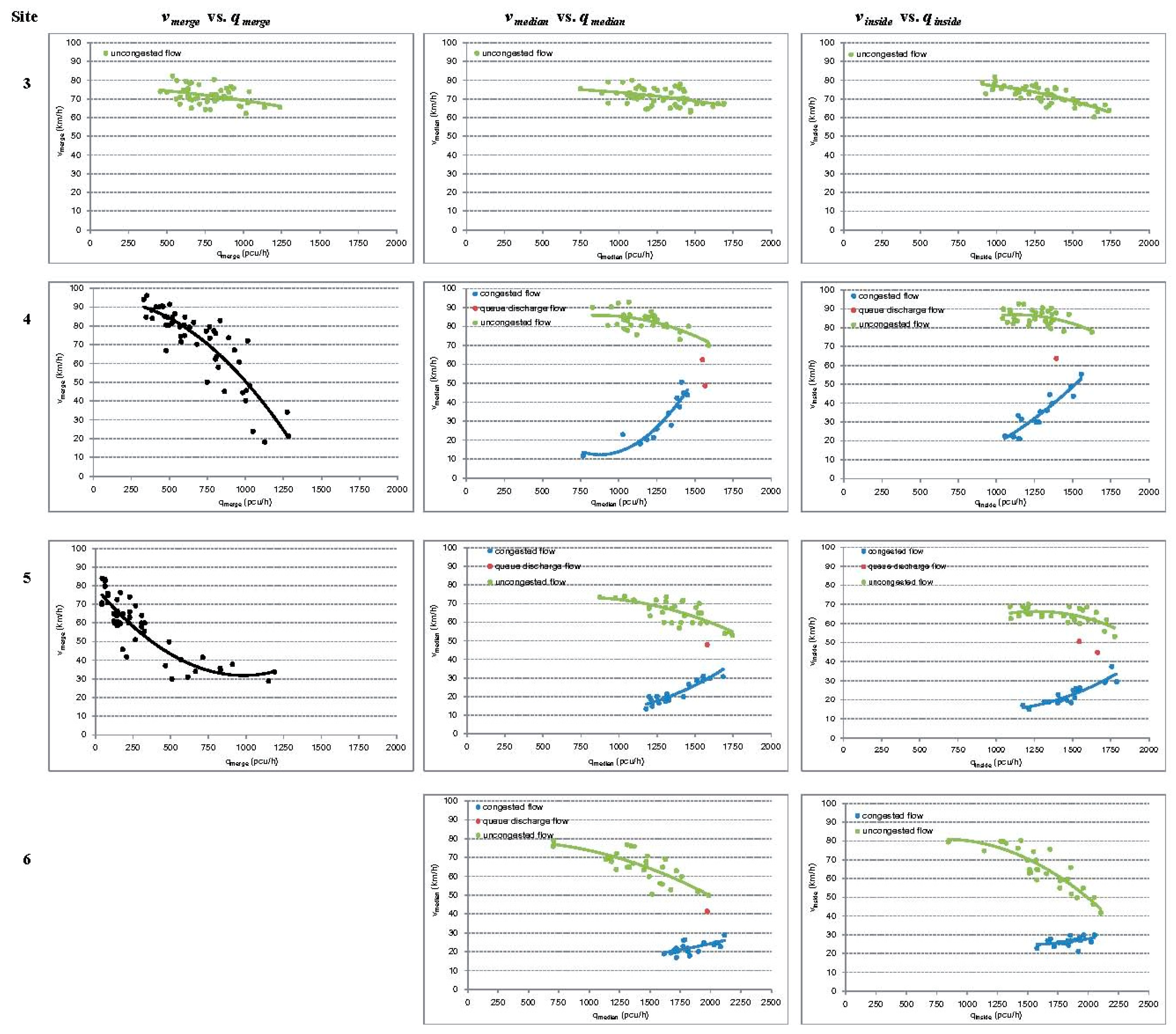
The sample distributions of lane speed-flow relationships (, , and ) from Site 3 to Site 6 are illustrated in sub-diagrams in Figure 5. and are lane speed and lane flow, respectively. Trend lines to the samples are also drawn in the diagrams. Since the diagrams in the column and the column in Figure 5 have an obvious piecewise structure, the samples extracted from uncongested flow, queue discharge flow, and congested flow are marked with different colors. Obvious capacity drop can be seen in these diagrams, which means that the traffic oscillations caused by merging vehicles exist in both the median lane and inside lane. Another noteworthy finding is that speed-flow relationships of merge-lane traffic at Site 4 and Site 5 do not follow a similar piecewise pattern. Thus, the samples in these two diagrams are colored black. A speed-flow model can be formulated for each lane, with traffic variables of itself and the adjacent lane as predictors, which are expressed as follows:
where is traffic density for i lane. Each model indicated in Equation (2) could have several expressions. The best model expression can be identified using the regression method to test the combinations of the involved traffic variables. The regression function explaining the largest proportion of the samples was selected to describe the lane speed-flow relationship. The estimated models are listed in Table 2, and the detailed regression results are listed in Table A1 in Appendix A. Except models for merge-lane traffic at Site 4 and Site 5, all models are estimated without the intercept item because the regression curve should pass the ( = 0, = 0) point in the speed-flow diagram.
4.1. Merge Lane
Compared with the median- and the inside-lane traffic, the speed-flow relationship of the merge-lane traffic presents significant changes at both the cross-section and longitudinal levels. As shown in Figure 5, the uncongested speed-flow curve for the merge lane at Site 3 seems similar to the one of the median lane and inside lane, but this similarity disappears at Site 4 and Site 5. The coefficient of continues to increase from Site 3 to Site 5 (in Table 2: −0.24 at Site 3, −0.09 at Site 4, 0.32 at Site 5), indicating that as increases, decreases the most at Site 3, decreases less at Site 4, and inversely increases at Site 5. This finding complies with the authors’ field observation. With higher speed or lower density of the merge-lane traffic, drivers’ merging positions are closer to the work zone. In the authors’ view, the distinctive speed-flow curve of the merge-lane traffic could be attributed to two causes. At first, as shown in Table 1, the proportion of the merge-lane flow with respect to the cross-section flow is always lower than the ones of the median lane and the inside lane, especially from Site 3 to Site 5. Without sufficient demand, traffic oscillation has difficulty forming in the merge lane, so capacity drop is not found in the speed-flow diagrams. In addition, some special merging behaviors observed only on the merge lane in the field could enable the vehicles in every speed range to be recorded in the traffic data of the merge lane.
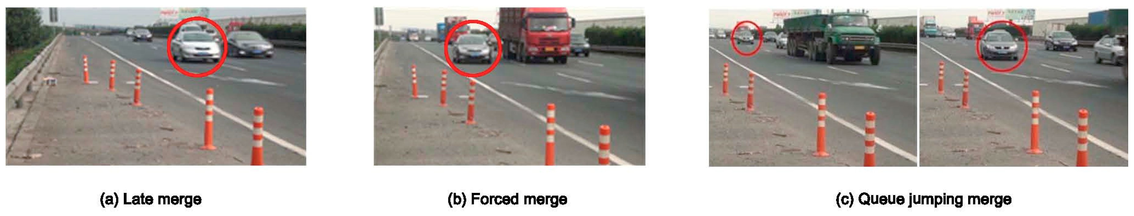
The first observed special behavior is late merge, which usually happens at a relatively low level of . As shown in Figure 6a, the circled vehicle in the merge lane runs side-by-side with the vehicle on the median lane. The merging driver reluctantly decelerated to insert behind the parallel vehicle at the upstream segment. The driver did not make the lane change until arriving at the start of the work zone taper (Site 5), or even ran along the taper looking for an opportunity to insert into the median lane (between Site 5 and Site 6). This merging behavior usually results in a high risk of a lateral collision. The second kind of special merging is the forced merge, which often happens under congestion flow. As shown in Figure 6b, since there was no acceptable lane changing gap in the median lane, the circled vehicle on the merge lane had to postpone its insertion again and again until it finally inserted into the median lane in the taper segment. The third visual shows an example of a queue-jumping merge. As shown in Figure 6c, such a merge often occurs when traffic density in the merge lane is lower than that in the median lane. The driver in the median lane, who wanted a better position, switched to the merge lane and passed one or more vehicles on the median lane before inserting back into the median lane. These special merging behaviors have been observed in some studies [22], but their influence on the lane speed-flow relationship is rarely discussed. Since the behaviors exist at each speed level, the speed-flow relationship of the merge-lane traffic presents as a continuous curve, as shown in the diagrams in the column, rather than piecewise curves in the diagrams shown in the other two columns of Figure 5.
4.2. Median Lane and Inside Lane
According to the sample distributions shown in the diagrams in the column and column in Figure 5, the piecewise speed-flow models are separately estimated for the congested flows and uncongested flows of the median lane and the inside lane. The samples of these two traffic regimes were divided according to the capacity drops shown in the diagrams. In most diagrams, the outliers of uncongested and congested flow, marked as red dots, are assumed to be caused by the queue discharge. Several trends can be found from the diagrams and the estimated lane speed-flow models, which will be detailed below.
First, when capacity drop appears, traffic speed reduction in the median lane is larger than that in the inside lane (in Table 2, Site 4: drops from 70 km/h to 50 km/h, while drops from 70 km/h to 55 km/h; Site 5: drops from 50 km/h to 30 km/h, while drops from 50 km/h to 35 km/h; Site 6: drops from 50 km/h to 30 km/h, while drops from 50 km/h to 40 km/h). Thus, speed reduction in the median-lane traffic caused by inserting vehicles could be more than that of the inside-lane traffic.
Second, in the cross-section perspective, it takes more time for the queue to discharge in the median lane than in the inside lane. This trend is explored by comparing the estimated coefficients of the quadratic term of traffic speed of of the median lane and the inside lane (the congested flow models in Table 2, Site 4: Cof. () = −0.93, Cof. () = −0.70; Site 5: Cof. () = −1.50, Cof. () = −1.35; Site 6: Cof. () = −3.40, Cof. () = −1.72). The coefficients of the are always smaller than that of , which means that in the congested condition, with increases in lane speed, increases more slowly than . This development could be owing to different characteristics of the inserting vehicles on the merge lane and the inside lane. As revealed in Section 3, both the median- and the inside-lane traffic flows are disturbed by merging vehicles. However, the vehicles from the merge lane to the median lane conduct mandatory lane changes, while the vehicles from the median lane to the inside lane conduct discretionary lane changes. Since mandatory lane changes in congested flow usually accompany forced merges, the vehicles on the median lane being inserted could suffer more severe speed reductions than their counterparts on the inside lane. When the inserting vehicle is a heavy vehicle, which is frequently seen on the merge lane, the speed reduction is even larger. All these different circumstances could make recovering from congested conditions more difficult for the median-lane traffic.
Third, queue discharge could amount to more time at the place closer to the work zone. This trend can be found by comparing the coefficients of of the congested flow (the congested flow models in Table 2, Cof. (): Site 4 = −0.93, Site 5 = −1.50, Site 6 = −3.40; Cof. (): Site 4 = −0.70, Site 5 = −1.35, Site 6 = −1.72). These coefficients indicate that with an increase in lane speed in congested conditions, lane flow could increase at a slower rate at the site near the work zone. In other words, queue discharge entails more time at the site near the work zone, and the congested condition could last longer there. Such a finding implies that the frequency of merging behavior increases with vehicles approaching the work zone. Thus, it is valid to infer that more merging vehicles at a location could increase the probability of an active bottleneck forming there. Additionally, the capacity loss of the work-zone segment could be reduced if merging drivers conduct their lane changes evenly along the upstream segment of the work zone. Since not all drivers comply with traffic regulations in China, such as frequent violations of the 60 km/h speed limit mentioned in Section 3, an early merge could be a better choice when the highway agency designs merging control strategies because doing so could balance the merging vehicles’ distribution to some degree along the work zone.
5. Conclusions
Work zones usually become highway capacity bottlenecks. This paper has investigated the spatial distribution of drivers’ merging behaviors along work zones from a macroscopic perspective. Lane flow distribution was applied to analyze the variance of probability of merging implementation from both cross-section and longitudinal perspectives. It was found that drivers’ merging choices vary with cross-section flow, average lane speed, and drivers’ distances to the work zone when they make decisions. More importantly, significant disturbances of merging vehicles from the merge-lane to the median-lane traffic were found to start upstream of the work zone, rather than at the start of the taper area only, and these disturbances can induce merging behaviors from the median lane to the inside lane.
Based on such findings, lane speed-flow relationships at different locations of the work zone were analyzed. It was found that merging vehicles could change the relationship at both the cross-section level and the longitudinal level. Merge-lane traffic presents different speed-flow relationships with that of other lanes. A one-piece monotonic relationship between lane flow and speed is illustrated. This relationship could originate from insufficient merging demand and special merging strategies on this lane. Due to the influence of vehicle insertions, median- and inside-lane traffic suffers obvious capacity drop, especially for median-lane traffic. It was also found that more merging behaviors occurring at some locations could make it more difficult for lane traffic to recover from congestion at that locus. This study’s results could be helpful in understanding bottleneck formations upstream of work zones, as well as design targeted merging control strategies for each lane at different locations along the work zone [23].
Although this study has successfully investigated spatial characteristics of merging behaviors and lane speed-flow relationships along the work zone, it leaves ample room for improvements. First, since the effect of static traffic control signs set at the studied work zone is limited, it is necessary to test dynamic merging control systems in the field. Such control systems are usually founded on accurate estimations of each lane capacity, which could vary during queue formation and discharge. Therefore, the capacity estimating model should be developed in the future. Second, only one work zone is taken as a study case in this paper; drivers’ attitudes to different configurations of work zones are difficult to estimate accurately. This issue should be addressed in future studies. Third, the traffic data was collected at the upstream segment and the start of the construction area of the work zone, but not deeply in the construction area and/or its downstream segment. Future studies could investigate the influence of diverging traffic appearing downstream of the work zone on the lane speed-flow relationship. Finally, vehicle trajectory can be extracted from the collected traffic video, which could be used to evaluate potential collision risk caused by the merging vehicles at the work zone [24] and to develop a microscopic traffic flow model for merging behavior [25].
Author Contributions
L.L. and D.Z. conceived and designed the research; L.L. collected the data; L.L. and D.Z. analyzed the data; and L.L. and D.Z. wrote and revised the paper.
Acknowledgments
The authors would like to acknowledge the National Natural Science Foundation of China (grant nos. 63174193, 71501014, 71701031, 51505037), Key Science and China Postdoctoral Science Foundation (grant no. 2016M600814), the Fundamental Research Funds for the Central Universities (grant nos. 3102017zy023, 300102328401, 300102328101, 300102328205), and the Key Laboratory of Road and Traffic Engineering of the Ministry of Education, Tongji University (grant no. K201601), which collectively funded this project.
Conflicts of Interest
The authors declare no conflict of interest.
Appendix A

Table A1.
Regression result of the estimated models.
| Site | Variable | t-Statistic | p-Value | Site | Variable | t-Statistic | p-Value | Site | Variable | t-Statistic | p-Value |
|---|---|---|---|---|---|---|---|---|---|---|---|
| 3 | Uncongested flow on merge lane | 3 | Uncongested flow on median lane | 3 | Uncongested flow on inside lane | ||||||
| −4.67 | <0.001 | −4.26 | <0.001 | −11.04 | <0.001 | ||||||
| 5.20 | <0.001 | 5.07 | <0.001 | 14.63 | <0.001 | ||||||
| 3.49 | <0.05 | 5.58 | <0.001 | -- | -- | -- | |||||
| 4 | Flow on merge lane | 4 | Uncongested flow on median lane | 4 | Congested flow on median lane | ||||||
| Intercept | 18.16 | <0.001 | −7.01 | <0.001 | −12.12 | <0.001 | |||||
| −12.73 | <0.001 | 9.98 | <0.001 | 23.84 | <0.001 | ||||||
| −1.96 | <0.05 | -- | -- | -- | -- | -- | -- | ||||
| 4 | Uncongested flow on inside lane | 4 | Congested flow on inside lane | 5 | Flow on merge lane | ||||||
| −4.48 | <0.001 | −7.00 | <0.001 | Intercept | 8.16 | <0.001 | |||||
| 5.56 | <0.001 | 14.56 | <0.001 | −4.03 | <0.05 | ||||||
| 3.25 | <0.05 | -- | -- | -- | 3.29 | <0.001 | |||||
| 5 | Uncongested flow on median lane | 5 | Congested flow on median lane | 5 | Uncongested flow on inside lane | ||||||
| −7.95 | <0.001 | −10.87 | −10.87 | −5.55 | <0.001 | ||||||
| 8.57 | <0.001 | 26.44 | <0.001 | 7.79 | <0.001 | ||||||
| 2.14 | <0.05 | -- | -- | -- | -- | -- | -- | ||||
| 5 | Congested flow on inside lane | 6 | Uncongested flow on median lane | 6 | Congested flow on median lane | ||||||
| −11.41 | <0.001 | −10.15 | <0.001 | −6.92 | <0.05 | ||||||
| 31.58 | <0.001 | 14.17 | <0.001 | 13.03 | <0.001 | ||||||
| 6 | Uncongested flow on inside lane | 6 | Congested flow on inside lane | ||||||||
| −14.92 | <0.001 | −3.63 | <0.001 | ||||||||
| 21.71 | <0.001 | 9.04 | <0.001 | ||||||||
References
- Weng, J.; Meng, Q. Estimating capacity and traffic delay in work zones: An overview. Transp. Res. Part C Emerg. Technol. 2013, 35, 34–45. [Google Scholar] [CrossRef]
- Weng, J.; Meng, Q. Incorporating work zone configuration factors into speed-flow and capacity models. J. Adv. Transp. 2015, 49, 371–384. [Google Scholar] [CrossRef]
- Ahn, S.; Laval, J.; Cassidy, M.J. Effects of merging and diverging on freeway traffic oscillations: Theory and observation. Transp. Res. Rec. J. Transp. Res. Board 2010, 2188, 1–8. [Google Scholar] [CrossRef]
- Zheng, Z.; Ahn, S.; Chen, D.; Laval, J. The effects of lane-changing on the immediate follower: Anticipation, relaxation, and change in driver characteristics. Transp. Res. Part C Emerg. Technol. 2013, 26, 367–379. [Google Scholar] [Green Version]
- Zheng, Z. Recent developments and research needs in modeling lane changing. Transp. Res. Part B Methodol. 2014, 60, 16–32. [Google Scholar] [Green Version]
- Meng, Q.; Weng, J. An improved cellular automata model for heterogeneous work zone traffic. Transp. Res. Part C Emerg. Technol. 2011, 19, 1263–1275. [Google Scholar]
- Bertini, R.L.; Leal, M.T. Empirical study of traffic features at a freeway lane drop. J. Transp. Eng. 2005, 131, 397–407. [Google Scholar]
- Ahn, S.; Cassidy, M.J. Freeway traffic oscillations and vehicle lane-change maneuvers. In Proceedings of the 17th International Symposium on Transportation and Traffic Theory, London, UK, 23–25 July 2007; Linacre House, Jordan Hill: Oxford, UK, 2007. [Google Scholar]
- Zhang, H.M.; Shen, W. Numerical investigation of stop-and-go traffic patterns upstream of freeway lane drop. Transp. Res. Rec. J. Transp. Res. Board 2009, 2124, 3–17. [Google Scholar] [CrossRef]
- Jin, W.L. A kinematic wave theory of lane-changing traffic flow. Transp. Res. Part B Methodol. 2005, 44, 1001–1021. [Google Scholar] [CrossRef]
- Jin, W.L. A multi-commodity Lighthill–Whitham–Richards model of lane-changing traffic flow. Transp. Res. Part B Methodol. 2013, 57, 361–377. [Google Scholar] [CrossRef]
- Avrenli, K.A.; Benekohal, R.; Ramezani, H. Determining the speed-flow relationshp and capacity for a freeway work zone. In Proceedings of the Transportation Research Board 90th Annual Meeting, Washington, DC, USA, 23–27 January 2011; Transportation Research Board: Washington DC, USA, 2011. [Google Scholar]
- Weng, J.; Meng, Q. Modeling speed-flow relationship and merging behaviour in work zone merging areas. Transp. Res. Part C Emerg. Technol. 2011, 19, 985–996. [Google Scholar]
- Avrenli, K.A.; Benekohal, R.F.; Ramezani, H. Four-regime speed-flow relationships for work zones with police patrol and automated speed enforcement. Transp. Res. Rec. J. Transp. Res. Board 2012, 2272, 35–43. [Google Scholar] [CrossRef]
- Duret, A.; Soyoung, A.; Christine, B. Lane flow distribution on a three-lane freeway: General features and the effects of traffic controls. Transp. Res. Part C Emerg. Technol. 2012, 24, 157–167. [Google Scholar]
- Samoili, S.; Efthymiou, D.; Antoniou, C.; Dumont, A.G. Investigation of lane flow distribution on hard shoulder running Freeways. Transp. Res. Rec. J. Transp. Res. Board 2013, 2396, 133–142. [Google Scholar]
- Wu, N. Equilibrium of lane flow distribution on motorways. Transp. Res. Rec. J. Transp. Res. Board 2006, 1965. [Google Scholar] [CrossRef]
- Maze, T.; Schrock, S.D.; Kamyab, A. Capacity of freeway work zone lane closures. In Proceedings of the Mid-Continent Transportation Symposium 2000, Ames, IA, USA, 15–16 May 2000; Iowa State University: Ames, IA, USA, 2000. [Google Scholar]
- Racha, S.; Chowdhury, M.; Sarasua, W.; Ma, Y. Analysis of work zone traffic behaviour for planning applications. Transp. Plan. Technol. 2008, 31, 183–199. [Google Scholar]
- Oh, S.; Yeo, H. Estimation of capacity drop in highway merging sections. Transp. Res. Rec. J. Transp. Res. Board 2012, 2286, 111–121. [Google Scholar]
- Oh, S.; Yeo, H. Impact of stop-and-go waves and lane changes on discharge rate in recovery flow. Transp. Res. Part B Methodol. 2015, 77, 88–102. [Google Scholar]
- Hallmark, S.; Oneyear, N. Modeling Merging Behaviour at Lane Drops; 2015/02//Final Report; Iowa State University: Ames, IA, USA, 2015; 51p. [Google Scholar]
- Yang, N.; Chang, G.L. Simulation-based study on a lane-based signal system for merge control at freeway work zones. J. Transp. Eng. 2009, 135, 9–17. [Google Scholar]
- Guido, G.; Saccomanno, F.; Vitale, A.; Astarita, V.; Festa, D. Comparing safety performance measures obtained from video capture data. J. Transp. Eng. 2011, 137, 481–491. [Google Scholar] [CrossRef]
- Astarita, V.; Guido, G.; Vitale, A.; Giofré, V. A new microsimulation model for the evaluation of traffic safety performances. Eur. Transp. Trasp. Eur. 2012, 51, 1–16. [Google Scholar]
Figure 1.
(a) Diagram of the formation of traffic oscillations at a work zone; and (b) the piecewise speed-flow diagram.
Figure 1.
(a) Diagram of the formation of traffic oscillations at a work zone; and (b) the piecewise speed-flow diagram.

Figure 2.
Configuration of the studied work zone and data collection sites.

Figure 3.
(a) Average lane flow distribution at each site; and (b) chain effect caused by merging vehicles on median lane and inside lane.
Figure 3.
(a) Average lane flow distribution at each site; and (b) chain effect caused by merging vehicles on median lane and inside lane.

Figure 4.
Relationships between lane flow proportion and cross-section flow/speed.

Figure 5.
Diagrams of lane speed-flow relationships.

Figure 6.
Special merging behaviors in the merge lane.

Table 1.
Average lane flow distribution.
| Site | |||
|---|---|---|---|
| 1 | 26.81% | 39.23% | 33.96% |
| 2 | 23.49% | 41.38% | 35.13% |
| 3 | 22.05% | 38.65% | 39.30% |
| 4 | 22.02% | 38.26% | 39.72% |
| 5 | 9.41% | 44.23% | 46.36% |
| 6 | -- | 48.33% | 51.67% |
| 7 | -- | 48.41% | 51.59% |
| 1–5 | 20.76% | 40.35% | 39.69% |
Table 2.
Estimated lane speed-flow models.
| Site | Estimated Model | Adjusted R2 |
|---|---|---|
| 3 | 0.968 | |
| 0.985 | ||
| 0.991 | ||
| 4 | 0.770 | |
| 0.987 | ||
| 0.995 | ||
| 0.993 | ||
| 0.995 | ||
| 5 | 0.743 | |
| 0.989 | ||
| 0.996 | ||
| 0.983 | ||
| 0.997 | ||
| 6 | 0.980 | |
| 0.993 | ||
| 0.987 | ||
| 0.996 |
© 2018 by the authors. Licensee MDPI, Basel, Switzerland. This article is an open access article distributed under the terms and conditions of the Creative Commons Attribution (CC BY) license (http://creativecommons.org/licenses/by/4.0/).
Share and Cite
MDPI and ACS Style
Li, L.; Zhang, D. Merging Vehicles and Lane Speed-Flow Relationship in a Work Zone. Sustainability 2018, 10, 2210. https://doi.org/10.3390/su10072210
AMA Style
Li L, Zhang D. Merging Vehicles and Lane Speed-Flow Relationship in a Work Zone. Sustainability. 2018; 10(7):2210. https://doi.org/10.3390/su10072210
Chicago/Turabian StyleLi, Li, and Dong Zhang. 2018. "Merging Vehicles and Lane Speed-Flow Relationship in a Work Zone" Sustainability 10, no. 7: 2210. https://doi.org/10.3390/su10072210
Note that from the first issue of 2016, this journal uses article numbers instead of page numbers. See further details here.