Study on Application Potential of Seasonal Thermal Energy Storage-Hybrid Ground Source Heat Pump in Taiwan—Taking Experiments in Tainan as Examples


1
Department of Architecture, National Cheng Kung University, 701, Taiwan
2
College of Real Estate, Beijing Normal University, Zhuhai 519087, China
*
Author to whom correspondence should be addressed.
Sustainability 2018, 10(6), 1746; https://doi.org/10.3390/su10061746
Submission received: 4 May 2018
/
Revised: 24 May 2018
/
Accepted: 24 May 2018
/
Published: 26 May 2018
(This article belongs to the Special Issue Sustainability in Civil Engineering: from Sustainable Materials to Sustainable Cities)
Abstract
:Ground source heat pumps (GSHPs) are widely used in building energy conservation in many countries and regions. However, they are rarely seen in Taiwan. The main reason is the extraordinary imbalance between the heating load and cooling load of buildings in Taiwan. Hybrid ground source heat pump (HGSHP) is a hybridization of a traditional GSHP system, and can effectively balance the heat injected into and extracted from the ground over an annual cycle. This study focuses on the application of seasonal thermal energy storage HGSHP (STES-HGSHP). Based on the data of six experiments in Tainan, Taiwan, this study finds out the ways to make the process of cold energy storage run with high efficiency, including (1) increasing the flow rate in the ground coupled heat exchanger (GCHE); (2) using double-U GCHE instead of single-U GCHE; (3) starting the process of cold energy storage at the time with low wet bulb temperature; (4) storing more cold energy than necessary in order to lower the ground temperature. Finally, by analyzing the level of wet bulb temperature in winter, this study confirms that the application of STES-HGSHP has great potential in Tainan.
1. Introduction
In Taiwan, electricity production of thermal power grew from 125,672.1 GWh in 2014, 131,068.1 GWh in 2015 to 139,144.4 GWh in 2016. Dependence on imported energy kept above 97% from 1996 to 2016. However, energy from renewable sources, such as biomass, waste, conventional hydro power, and solar and wind power, only rose slightly, from 1.33% in 2000 to 1.80% in 2016 [1].
Due to the hot climate, air conditioners consumed 13% of total energy consumption in Taiwan [2]. If ground source heat pumps (GSHPs) can be applied to the air conditioning (AC) systems, especially those in public and commercial buildings, the energy consumption and dependence on imported energy in Taiwan will be reduced.
GSHPs are widely used in building energy conservation in many countries and regions. By the end of 2015, the installed capacity of geothermal (ground source) heat pumps reached 50,258 MWt, an increase of 51.7% from 33,134 MWt in 2010, about 27 times as many as in 1995 [3].
Although GSHPs are used in more and more areas in the world, they are rarely seen in Taiwan. The main reason is the extraordinary imbalance between cooling load and heating load of buildings in Taiwan. Thermal imbalance can cause the significant rise or fall in ground temperature, degrade the performance, or even lead to a failure of GSHP system, which has been demonstrated in many research studies and analyses [4,5,6].
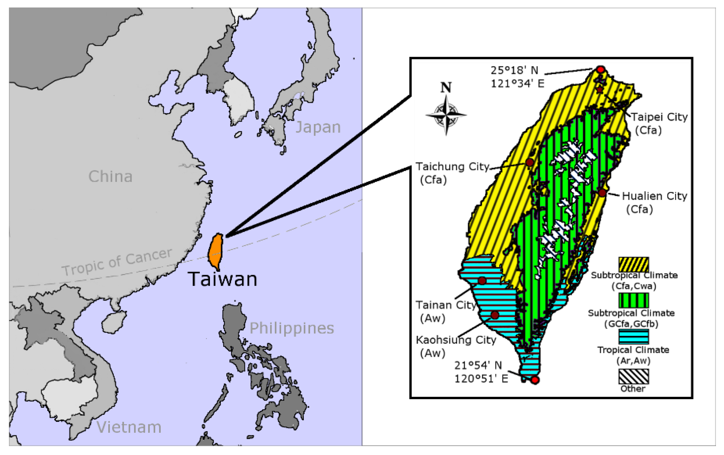
The climate of Taiwan is hot and often humid all year round. It can be classified as subtropical climate in North, East, and West Taiwan, and as tropical climate in South Taiwan [7]. Most high-density urban areas are located in these regions (see Figure 1).
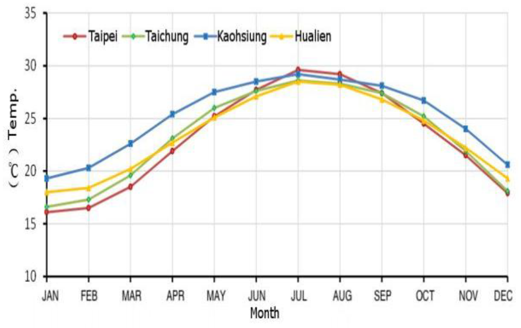
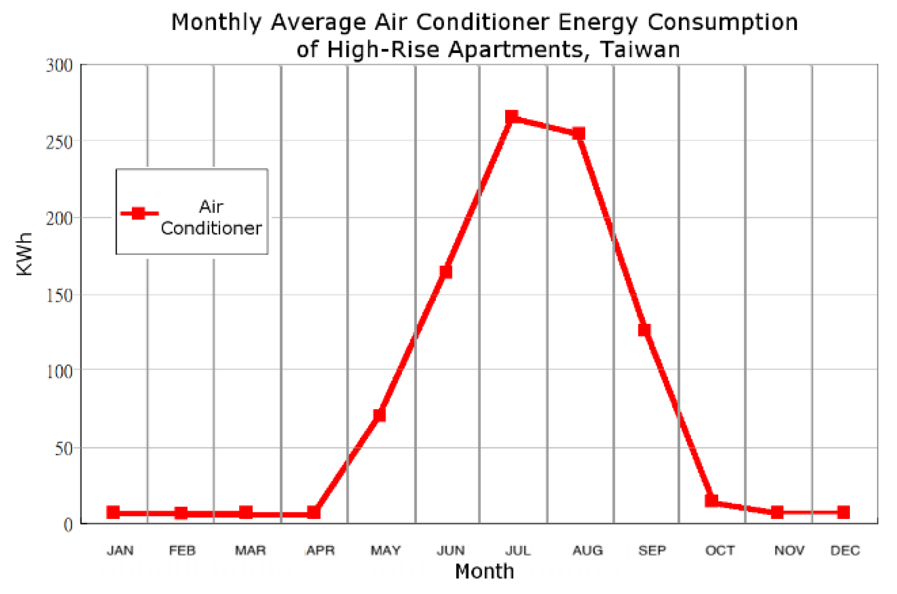
Figure 2 shows that monthly average temperatures of the main urban areas in Taiwan remain above 15 °C from 1981 to 2010 [8]. Due to the hot climate, the cooling load of buildings in Taiwan is larger than the heating load. The energy consumption of cooling is much higher than heating. Figure 3 provides an analysis of monthly average air conditioner energy consumption of high-rise apartments in Taiwan [9], which shows that in a year-round observation, the energy consumption of air conditioner mainly occurs between May to October, and there is little energy consumption between November to April.
Since the air conditioning load of most buildings in Taiwan is mainly the cooling load, there is an extraordinary imbalance between heating load and cooling load. If the GSHP is connected directly to the AC system, the heat injected into the ground in the summer will be far more than the heat extracted from the ground in the winter. The ground temperature balance will be destroyed, resulting in increased ground temperature and the degradation of system efficiency, year by year.
In addition, underground temperature in Taiwan is relatively higher than other regions at the same latitude. According to the investigation on temperature of hundreds of wells with depth of 10 to 100 m in Taiwan by Sugar Corporation Tainan Branch in 2005, the underground temperature of Taipei, a city located in North Taiwan at latitude of 25°13′ N, is in the range of 22.1–25.2 °C, with an average temperature of 23.91 °C; the underground temperature of Tainan, a city located in South Taiwan at latitude 22°59′ N, is in the range of 25.3–27.4 °C, with an average temperature of 26.14 °C [10].
Therefore, there are two main problems that restrain the application of GSHPs in Taiwan:
- (1)
- an extraordinary imbalance between heating load and cooling load of buildings;
- (2)
- high ground temperature.
If only these two problems can be overcome, will GSHPs have good performance in Taiwan.
Taking into account the climate condition and character of building air conditioning in Taiwan, this study focuses on hybrid ground source heat pumps (HGSHPs).
HGSHP is a hybridization of a traditional GSHP system. According to the definition by Chiasson, the hybridization of geothermal heat pump systems is accomplished by incorporating supplemental heat rejection or addition equipment, such as cooling towers, fluid coolers, boilers, and solar collectors, with the ground heat exchanger (GHE) loop [11].
Many studies and projects prove that HGSHP can effectively balance the heat injected into and extracted from the ground over an annual cycle, which will ensure the sustainability of the whole system. The study of Li et al. [12] shows that in large commercial and public buildings or in hot climate zones, cooling towers added to GSHP systems can obviously improve the efficiency of heat pump units. The study of Zhang et al. [13] shows that HGSHP can effectively neutralize the accumulated heat in the soil and maintain the underground thermal balance. The study of Chiasson [11] shows that HGSHP may be used to completely balance ground thermal load on an annual basis.
HGSHP, having the advantage to balance the original unbalanced heating and cooling load, can be used in more regions or buildings than traditional GSHP. The study of Hesaraki et al. [14] concludes that HGSHP has a very significant energy saving effect based on systematical analysis of many HGSHP systems around the world.
In Taiwan, if HGSHP can be introduced, the extraordinary imbalance between heating load and cooling load of buildings will be balanced. Furthermore, if the HGSHP can over extract the heat from underground in winter, the underground temperature will be reduced, even below the original value. Lower underground temperature can make HGSHP have better performance in the next-year’s cycle. This process can be called underground thermal energy storage (UTES), which is a widely used technology for both heat and cold storage [15,16].
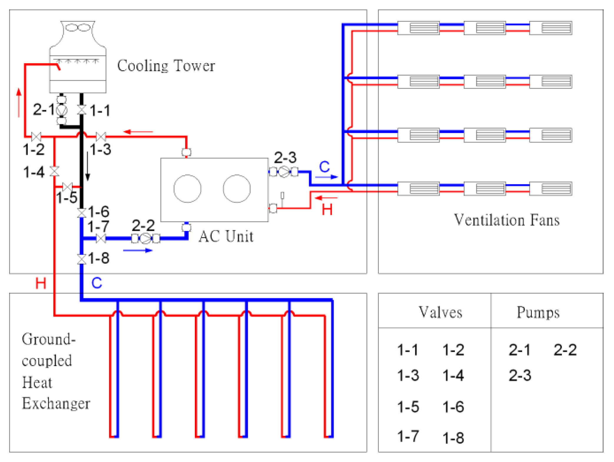
Because cooling load in summer is far greater than heating load in winter, HGSHP used in Taiwan is designed to connect the cooling tower to the traditional GSHP system. During summer, the HGSHP injects heat into soil by ground-coupled heat exchanger (GCHE). During winter, the cooling tower provides cold water to GCHE and extracts the heat from soil. In other words, the HGSHP can store cold energy in winter for cooling in the following summer. This kind of HGSHP can be more accurately called seasonal thermal energy storage-hybrid ground source heat pump (STES-HGSHP).
Figure 4 shows a system diagram of STES-HGSHP. According to different circumstances, it can run in several modes. Table 1 shows three most adopted modes and gives the status of valves and pumps under different modes.
Mode 1 runs in summer when the air wet bulb temperature is less than or equal to the ground temperature. In this mode, the cooling tower is connected to air conditioning unit and the GCHE is shut off and out of the water circulation loop.
Mode 2 runs in summer when the air wet bulb temperature is greater than the ground temperature. In this mode, GCHE is connected to air conditioning unit and the cooling tower is shut off and out of the water circulation loop.
Mode 3 runs in winter when the air wet bulb temperature is lower than the ground temperature. In this mode, the cooling tower is connected to GCHE. The cooling tower provides cold water to GCHE so that the heat accumulated in soil can be extracted out, the ground temperature can be lowered, and the cold energy of winter can be stored into soil.
Taiwan’s climate provides good conditions for sustainable running of the STES-HGSHP. For example, according to temperature data of TMYK3 [17], in Taipei, a city in North Taiwan with latitude of 25°13′ N and average ground temperature of 23.91 °C [10], the air wet bulb temperatures from November to February are between 6.34 and 23.98 °C with average of 16.28 °C, and almost all lower than the average ground temperature. In this period, STES-HGSHP can store a large amount of cold energy for cooling in the following summer. In another city, Tainan, a city in South Taiwan with latitude of 22°59′ N and average ground temperature of 26.14 °C [10], the air wet bulb temperatures from November to February are between 5.64 and 25.38 °C, with average of 16.99 °C, and all lower than the average ground temperature. The climate conditions for usage of STES-HGSHP in Tainan are even better than Taipei.
In this study, it is assumed that the STES-HGSHP injects heat into the ground in summer, and in winter, the cold water produced by the cooling tower is pumped into GCHE to extract the accumulated heat in soil. If the heat extracted in winter is more than the heat injected in summer, the underground temperature will be reduced below the initial value, which will provide better conditions for running of STES-HGSHP in the following summer.
Thus, in Taiwan, effective application of STES-HGSHP can firstly eliminate the imbalance between heating and cooling load of buildings, and secondly, store more cold energy into ground to lower the ground temperature for higher efficiency in follow summer.
In order to provide evidence to support the feasibility of STES-HGSHP, this study focuses on cold energy storage in winter by launching a series of experiments in Tainan, and summarizes the characteristics and potential performance of cold energy storage process on the basis of experimental data.
2. Experimental System
The experimental site is located in Performance Experiment Center of Tainan, Architecture and Building Research Institute, Ministry of the Interior, Taiwan at 22°56′11.45′′ N latitude and 120°16′24.62′′ E longitude. The climate type of the site is AW (tropical humid climate, with rainy season in the summer and dry in winter) [7].
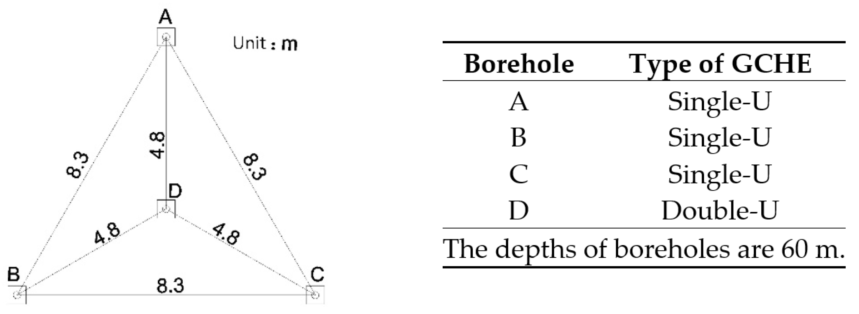
There are four boreholes (named A–D) with same depth of 60 m at the site. A–C are arranged in an equilateral triangle with single-U GCHE inside. D, with same distance to other three boreholes and double-U GCHE inside, is put in the middle of the triangle (Figure 5). A, B, and D are used in experiments of this study, while C is used as a backup borehole.
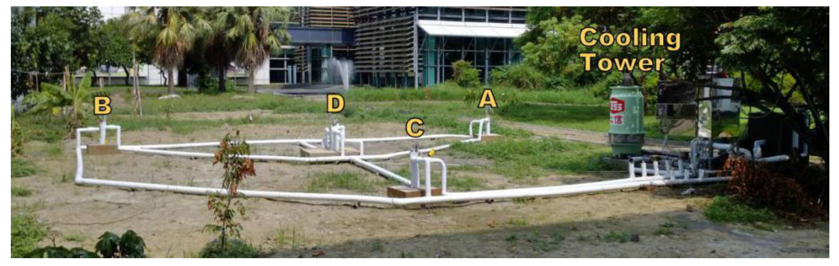
All boreholes are connected parallel to a cooling tower. A water pump is added into the loop for water circulation, and some valves control which borehole is involved in an experiment. This system can provide many combinations of experimental conditions (Figure 6).
The GCHEs are made of DN25 high density polyethylene pipe (HDPE) with an outer diameter of 25 mm and inner diameter of 20.4 mm.
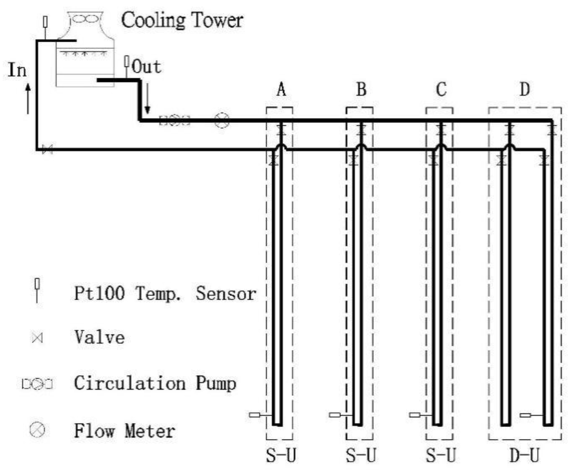
Figure 7 shows the schematic of experimental equipment. Since the sensor signal transmission distance is very long, three-wire PT100 temperature sensors are used, instead of two-wire PT100 sensors. There is a total of six sensors. Two of them are placed at the inlet and outlet of the cooling tower. The remaining four are placed inside each borehole at 53.5 m underground.
The calibration of sensors is performed using a standard glass thermometer with resolution of 0.1 °C, certified by Electronics Testing Center, Taiwan.
The actual power consumption of cooling tower and circulation pump are 0.12 kW and 0.75 kW respectively. Total power consumption of the experimental system (Qs) is 0.87 kW.
On 1 July 2015, the construction of the experimental site was finished. Until 11 July, there was no experiment launched in order to eliminate the impact of the construction on the ground temperature. The average ground temperature at a depth of 53.5 m was 27.56 °C on 11 July.
In the period from 17 July 2015 to 30 November 2015, boreholes A, B, and D were alternately conducted in a variety of heat transfer experiments. A large amount of heat was injected into the three boreholes, increasing the ground temperature significantly.
According to the previous experimental experience, within the first 40 h after the start or the end of the experiments, it recorded the most obvious change in ground temperature. After that, the temperature change was very small and could be regarded as quasi-steady state.
The cold energy storage experiments described below were carried out at least 100 h after the above experiments, in order to minimize the impact on ground temperature fluctuations brought by previous experiments.
3. Design and Purpose of Cold Energy Storage Experiments
During the period from 30 November 2015 to 16 January 2016, six cold energy storage experiments were conducted. In these experiments, a cooling tower provided cold water, which was pumped into GCHE in order to inject cold energy into the ground. During the experiments, the entering and leaving water temperature of the cooling tower, and ground temperatures of boreholes at 53.5 m depth, were recorded every minute, as the basis for data analysis.
Four of these experiments were conducted during the period from 30 November 2015 to 20 December 2015, and only stored cold energy at night. Since the daytime temperature was still high in this period, the time for cold energy storage was set at night from 17:00 to 7:00 (total 14 h per day). For each experiment, a different water flow rate was set, to assess its impact on the experimental results.
The other two experiments were conducted during the period from 10 January 2016 to 16 January 2016. During this period, the temperature at day and night was low enough to carry out uninterrupted experiments, 24 hours a day.
The main information of these six experiments is summarized in Table 2.
Experiments #1, #2, and #4 used borehole A and B with single-U GCHE inside, and set different flow rates in order to compare the effect of cold energy storage in different conditions. Experiment #3 used borehole D with dingle-U GCHE inside, and set the flow rate similar to experiment #1, in order to compare the effects of cold energy storage between single-U and double-U GCHE. In these four experiments, the cold energy storage process was carried out only at night.
Experiments #5 and #6 used borehole D with dingle-U GCHE inside, and set different flow rates in order to compare the effect of cold energy storage in different conditions. In these two experiments, the cold energy storage process was carried out continuously, 24 hours a day.
According to the leaving and entering water temperature of cooling tower (Tlw and Tew) and volume flow rate (V) recorded in process of experiments, heat transfer rate (Q) can be calculated by Equation (1). Average heat transfer rate at the stage of cold energy storage (Qa) can be calculated by Equation (2).
where:
Q = Cρ (Tlw − Tew) V/3600
Qa = Cρ (Talw − Taew) V/3600
- Q is heat transfer rate, kW
- Qa is average heat transfer rate at the stage of cold energy storage, kW
- C is water heat capacity, here is 4.178 kJ/(kg.K) at 1 atm and 40 °C
- ρ is water density, here is 992.2 kg/m3 at 1 atm and 40 °C
- Tlw is leaving water temperature of cooling tower, °C
- Tew is entering water temperature of cooling tower, °C
- Talw is average leaving water temperature of cooling tower at the stage of cold energy storage, °C
- Taew is average entering water temperature of cooling tower at the stage of cold energy storage, °C
- V is volume flow rate in one experiment, m3/h.
4. Analysis of Experimental Data
This study recorded a large amount of data. For the convenience of comparison, only the data of experiments #1 and #6 are listed here as representatives. The following Table 3 and Table 4, show data of the experiments #1 and #6, respectively. Although the original data were recorded minutely, these tables only list the data with an interval of two hours, in order to limit the number of pages of this paper.
Table 3 provides the data of experiment #1 in borehole B. As shown in Table, it can be seen that during the process of cold energy storage at nighttime, the ground temperature of borehole B at 53.5 m depth (Tg,bb) decreased significantly. During the day when the experiment was suspended due to high ambient temperature, the ground temperature began to rise, but still obviously lower than the temperature at the beginning of that experiment, indicating that the process of cold energy storage played an obvious role in extracting heat from underground.
Table 4 provides some data of experiment #6. The data interval is also two hours. It can be seen that the process of cold energy storage also played an obvious role in extracting heat from underground during the experiment.
In Table 3 and Table 4, the rows with Q not equal to 0 are data during the process of cold energy storage. The other rows are data during suspension of the experiment. In this paper, all data of dry bulb temperature (Tdb) and relative humidity (RH) are from Data Inquire System, Central Weather Bureau, Taiwan [18]. All data of wet bulb temperature (Twb) are calculated according to Liu’s method [19].
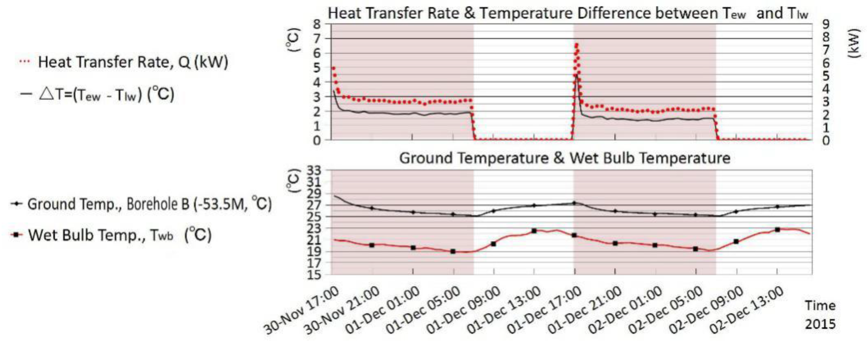
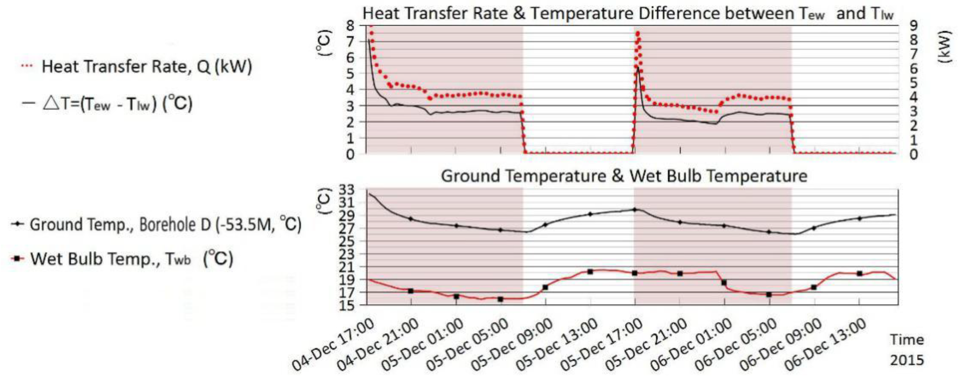
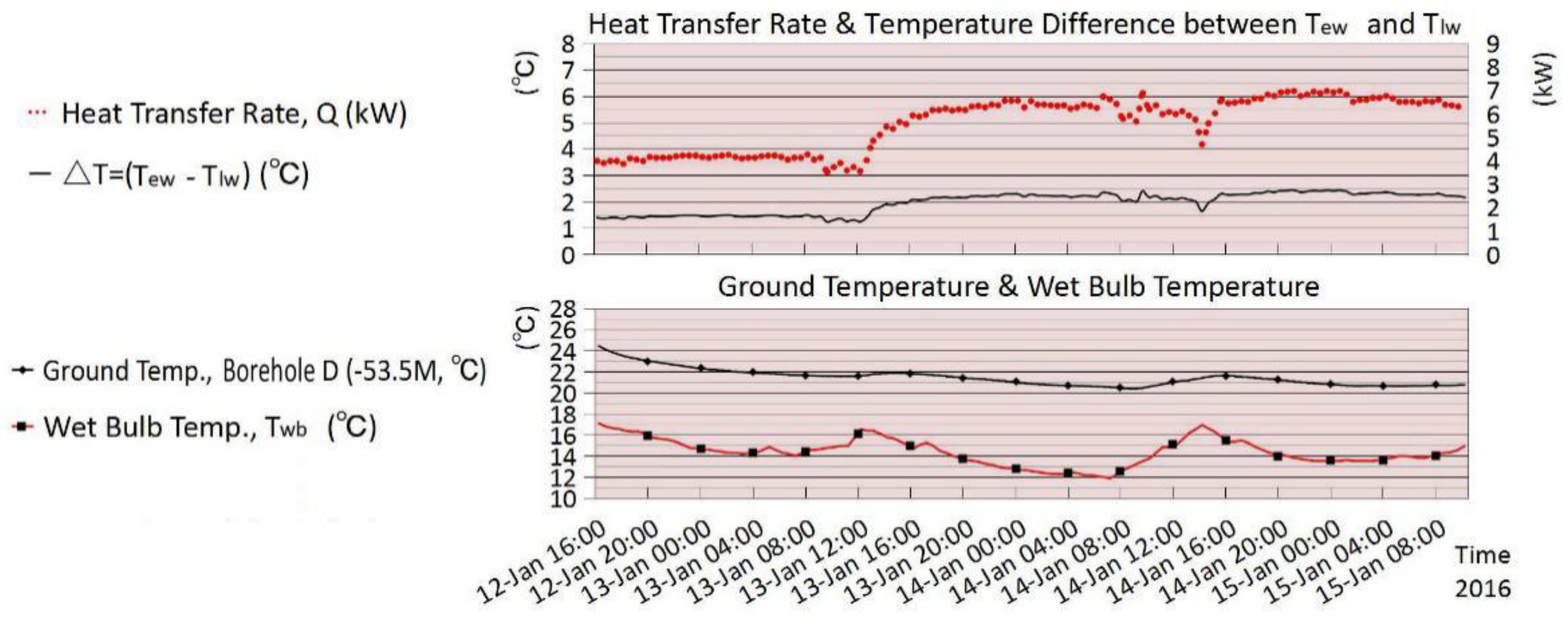
Based on the experimental data, Figure 8, Figure 9, Figure 10, Figure 11, Figure 12 and Figure 13, representing experiments #1 to #6, respectively, were drawn out to show the changes of heat transfer rate, temperature difference between Tlw and Tew, ground temperature, and wet bulb temperature during each experiment.
It can be seen from Figure 8, Figure 9, Figure 10, Figure 11, Figure 12 and Figure 13 that the effect of wet bulb temperature on the efficiency of cold energy storage is very significant. Lower wet bulb temperature means higher efficiency. In each experiment, ground temperature was significantly reduced when the experiment was in process of cold energy storage, indicating that this process had good performance in extracting the heat in soil.
It also can be seen from these figures that the heat transfer rates (Q) varied in each experiment because of the different volume flow rates (V).
For easy comparison, the average heat transfer rates at the stage of cold energy storage (Qa) are calculated and listed with other parameters in Table 5.
Experiments #1, #2, and #4, conducted in boreholes with single-U GCHE inside, set different volume flow rates (V), which were 1.4120, 0.6114, and 0.2127 m3/h, respectively. The impact of different flow rates on the heat transfer efficiency (Q or Qa) is very obvious. A positive correlation exists between flow rate and heat transfer efficiency. Greater flow rate means higher efficiency of heat transfer. However, a negative correlation exists between flow rate and the difference between inlet and outlet water temperature (△T or △Ta). The smaller the flow rate, the greater the temperature difference, and vice versa.
Experiment #3, conducted in borehole with double-U GCHE inside, had a set volume flow rate (V) and fluid flowing speed (S) similar to the flow rate in experiment #1, and fluid flowing speed in experiment #2, respectively. Through comparison, it is clearly seen that under the similar conditions, the heat transfer efficiency of the double-U GCHE is obviously better than that of the single-U GCHE, which means it is much better to use double-U GCHE than single-U GCHE.
In order to further analyze the relationship between flow rate and heat transfer efficiency, Table 6 lists the heat transfer efficiency values at the wet bulb temperature of 19.0 °C in experiments #1, #2, and #4, all conducted in boreholes with single-U GCHE inside. Table 7 lists the heat transfer efficiency values at the wet bulb temperature of 16.0 °C in experiments #3, #5, and #6, all conducted in boreholes with double-U GCHE inside.
Through comparison, it can be seen that at the same wet bulb temperature, the flow rate is highly positively related to the heat transfer efficiency, and negatively related to temperature difference. Higher flow rate will inevitably lead to greater efficiency and smaller temperature difference.
In addition, the level of wet bulb temperature also has a very significant impact on the heat transfer efficiency. Table 8 shows the relationship between wet bulb temperature and heat transfer efficiency in experiment #6. It can be clearly seen that the lower air wet bulb temperature leads to the higher efficiency. That means wet bulb temperature is highly negatively related to the heat transfer efficiency.
In Table 8, another feature worth mentioning is the high coefficient of performance (COP) when wet bulb temperature is lower than 17 °C, which means that the heat transfer efficiency of GCHE in this condition is very high. This gives a good reason for the application of this system.
5. Application Suggestions for Tainan, Taiwan
Through the experiments of this study, it can be seen that the process of cold energy storage in Tainan, Taiwan, has a significant effect in extracting the heat from the ground, which can eliminate the adverse effect of imbalance between heating and cooling load.
In order to achieve better cold energy storage effect, the following arrangements can be adopted:
- (1)
- increasing the flow rate in the GCHE;
- (2)
- using double-U GCHE instead of single-U GCHE;
- (3)
- choosing the time with low wet bulb temperature;
- (4)
- storing more cold energy than necessary in order to lower the ground temperature and provide better conditions for running of HGSHP in the following summer.
The winter of Tainan is short, but still provides good conditions for launching cold energy storage. Figure 14 shows the total hours when wet bulb temperature was below 17 °C, from 1 October to 31 March during 2012–2017. It can be seen that in each of these years, cold energy storage can be conducted with high efficiency in at least more than 1300 h. If a higher wet bulb temperature is set, there will be more hours for cold energy storage.
Table 9 provides statistics about hours below certain wet bulb temperature from October 1 to March 31 in the recent years in Tainan. It can be seen that there is ample time to conduct cold energy storage in this period of each year.
In large buildings, because of the huge amount of cooling load in summer, it is better to combine the STES-HGSHP with a traditional air conditioning system. In small buildings, GCHE can connect with the wall or floor capillary tube mats directly, and cool the rooms down by providing cold water into mats. However, regardless of the system used, a life cycle assessment (LCA) is necessary and important, to ensure the long-term system sustainability [20].
All in all, because of the high efficiency of cold energy storage in winter, the colder energy that is stored in winter, the more energy that will be saved in summer.
6. Conclusions
In Taiwan, there are extraordinary imbalances between the heating and cooling load of buildings. The cooling load is much higher than the heating load in an annual cycle. Regarding the many technologies of GSHP, HGSHP will be a very good solution for Taiwan. Focusing on cold energy storage of STES-HGSHP in winter, this study launched a series of experiments to find a way to make the process of cold energy storage run with high efficiency. Finally, it was proven that the process of cold energy storage has great potential in extracting the heat accumulated in ground, and can be conducted with high efficiency.
This study shows that, in process of cold energy storage in winter, (1) higher flow rate in the GCHE means higher heat transfer efficiency; (2) the performance of double-U GCHE is much better than single-U GCHE; (3) the lower the wet bulb temperature, the higher the heat transfer efficiency.
This study also demonstrates that the process of cold energy storage can achieve high COP. For example, experiment #6, which was launched in borehole D with double-U GCHE inside with a volume flow rate of 2.47 m3/h, achieved COPa up to 5.7, 6.5, and 7.3 in the period when the wet bulb temperature was lower than 17 °C, 15 °C, and 13 °C, respectively.
Finally, this study analyzes the data of wet bulb temperature in recent winters in Tainan, Taiwan. The results show that the period with low wet bulb temperature each year is ample for launching cold energy storage in Tainan.
Therefore, both the heat transfer efficiency and the climatic temperature conditions confirm that STES-HGSHP is highly viable in Tainan.
However, this study has not considered the impact of groundwater flow and the different diameters of tubes buried in the ground. Further research is expected to clarify these issues.
Author Contributions
Conceptualization, P.L. and H.-T.L.; Methodology, P.L. and H.-T.L.; Software, N/A; Validation, P.L. and H.-T.L.; Formal Analysis, P.L.; Investigation, N/A; Resources, P.L.; Data Curation, P.L.; Writing-Original Draft Preparation, P.L.; Writing-Review & Editing, P.L. and H.-T.L.; Supervision, H.-T.L.; Project Administration, P.L.; Funding Acquisition, H.-T.L.
Funding
This research was funded by Architecture and Building Research Institute, Ministry of the Interior, Taiwan.
Acknowledgments
Special acknowledgment is given to Architecture and Building Research Institute for financial support from the Collaborative Research Project (Project No.: 10415B0004), and to Performance Experiment Center of Tainan for the experimental site and technical support.
Conflicts of Interest
The authors declare no conflict of interest. The founding sponsors had no role in the design of the study; in the collection, analyses, or interpretation of data; in the writing of the manuscript, and in the decision to publish the results.
Nomenclature
| △T | temperature difference, △T = (Tew − Tlw) (°C) |
| △Ta | average temperature difference at the stage of cold energy storage, △Ta = (Taew − Talw) (°C) |
| C | water heat capacity (1 atm, 40 °C, 4.178 kJ/(kg.K)) |
| COP | coefficient of performance |
| COPa | average coefficient of performance |
| Q | heat transfer rate (kW) |
| Qa | average heat transfer rate at the stage of cold energy storage (kW) |
| Qs | total power consumption of the experimental system (0.87 kW in this study) |
| RH | relative humidity (%) |
| S | fluid flowing speed in GCHE (m/s) |
| Taew | average entering water temperature of cooling tower at the stage of cold energy storage (°C) |
| Talw | average leaving water temperature of cooling tower at the stage of cold energy storage (°C) |
| ρ | water density (1 atm, 40 °C, 992.2 kg/m3) |
| Tawb | average wet bulb temperature at the stage of cold energy storage (°C) |
| Tdb | dry bulb temperature (°C) |
| Tew | entering water temperature of cooling tower (°C) |
| Tg | ground temperature (°C) |
| Tg,ba | ground temperature of borehole A at 53.5 m depth (°C) |
| Tg,bb | ground temperature of borehole B at 53.5 m depth (°C) |
| Tg,bd | ground temperature of borehole D at 53.5 m depth (°C) |
| Tgb | ground temperature at the beginning of cold energy storage at 53.5 m depth (°C) |
| Tge | ground temperature at the end of cold energy storage at 53.5 m depth (°C) |
| Tlw | leaving water temperature of cooling tower (°C) |
| Twb | wet bulb temperature (°C) |
| V | volume flow rate (m3/h) |
References
- Bureau of Energy. Energy Statistics Handbook 2016; MOEA of Taiwan: Taipei, Taiwan, 2017; pp. 11, 27, 77. ISSN 1726-3743. [Google Scholar]
- Yew-Khoy, C. Discussion on the Solution of Energy Consumption of Building Air Conditioning—Taking Taiwan as an Example. In Proceedings of the 2011 Cross-Strait Climate Change & Sustainable Energy Forum, Taipei, Taiwan, 1–2 October 2011; Available online: https://taise.org.tw/uploadfile/file/2011Cross-Essay/B1_%E5%BB%BA%E7%AF%89%E7%A9%BA%E8%AA%BF%E8%80%97%E8%83%BD%E7%9A%84%E8%A7%A3%E6%B1%BA%E6%96%B9%E6%A1%88%E6%8E%A2%E8%A8%8E%E2%80%94%E4%BB%A5%E5%8F%B0%E7%81%A3%E7%82%BA%E4%BE%8B.pdf (accessed on 25 April 2018).
- John, W.L.; Tonya, L.B. Direct utilization of geothermal energy 2015 worldwide review. Geothermics 2016, 60, 66–93. [Google Scholar]
- Zhao, Z.; Shen, R.; Feng, W.; Zhang, Y.; Zhang, Y. Soil Thermal Balance Analysis for a Ground Source Heat Pump System in a Hot-Summer and Cold-Winter Region. Energies 2018, 11, 1206. [Google Scholar] [CrossRef]
- Shang, Y.; Li, S.; Li, H. Analysis of geo-temperature recovery under intermittent operation of ground-source heat pump. Energy Build. 2011, 43, 935–943. [Google Scholar] [CrossRef]
- Chen, S.; Mao, J.; Han, X.; Li, C.; Liu, L. Numerical Analysis of the Factors Influencing a Vertical U-Tube Ground Heat Exchanger. Sustainability 2016, 8, 882. [Google Scholar] [CrossRef]
- Chiou, C.-R.; Yu-Chi, L.; Liang, Y.-J.; Huang, M.-Y. A Study of Delineation and Application of the Climatic Zones in Taiwan. J. Taiwan Geogr. Inf. Sci. 2004, 1, 41–62. [Google Scholar]
- CWB, Taiwan. Available online: http://www.cwb.gov.tw/V7/climate/climate_info/taiwan_climate/taiwan_1.html (accessed on 13 April 2017).
- Kung, P.-Y. A Study on Electrical Consumption Survey and Evaluation System of Residential Buildings. Doctor Dissertation, Department of Architecture, National Cheng Kung University, Tainan, Taiwan, 2005. [Google Scholar]
- Taiwan Sugar Corporation Tainan Branch. Groundwater Quality Monitoring and Analysis for Taiwan Groundwater Monitoring Network (2/2); Water Resources Agency, Ministry of Economic Affairs: Taipei, Taiwan, 2005; ISBN 9860041369. [Google Scholar]
- Chiasson, A.D.; Yavuzturk, C.C.; Johnson, D.W.; Filburn, T.P. Optimization of the ground thermal response in hybrid geothermal heat pump systems. ASHRAE Trans. 2010, 116, 512–524. [Google Scholar]
- Kai-Yuan, L.; Jing-Gang, W. Economics Analysis of Hybrid Ground Source Heat Pump Systems with Cooling Tower as a Supplemental Heat Rejecter. Constr. Conserv. Energy 2007, 35, 58–61. Available online: http://dx.doi.org/10.3969/j.issn.1673-7237.2007.01.016 (accessed on 25 April 2018).
- Xiang, Z.; Zheng-Hua, R.; Da-Peng, L.; Sheng-Ming, L. Control Strategies for Hybrid Ground Source Heat Pump System Based on Soil Heat Balance. Build. Energy Effic. 2013, 41, 8–12. Available online: http://dx.doi.org/10.3969/j.issn.1673-7237.2013.06.003 (accessed on 25 April 2018).
- Hesaraki, A.; Holmberg, S.; Haghighat, F. Seasonal thermal energy storage with heat pumps and low temperatures in building projects—A comparative review. Renew. Sustain. Energy Rev. 2015, 43, 1199–1213. [Google Scholar] [CrossRef]
- Sliwa, T.; Rosen, M. Natural and Artificial Methods for Regeneration of Heat Resources for Borehole Heat Exchangers to Enhance the Sustainability of Underground Thermal Storages: A Review. Sustainability 2015, 7, 13104–13125. [Google Scholar] [CrossRef]
- Sarbu, I.; Sebarchievici, C.A. Comprehensive Review of Thermal Energy Storage. Sustainability 2018, 10, 191. [Google Scholar] [CrossRef]
- Ming-Chin, H.; Kuo-Tsang, H.; Jen-Chun, W. The Development and Research on Hourly Typical Meteorological Years (TMY3) for Building Energy Simulation Analysis of Taiwan; Architecture and Building Research Institute, Ministry of the Interior: New Taipei City, Taiwan, 2013; ISBN 978986039661-4. Available online: https://www.abri.gov.tw/en/research/dl/2479/14479301561.pdf (accessed on 25 April 2018).
- CWB Observation Data Inquire System, Taiwan. Available online: http://e-service.cwb.gov.tw/HistoryDataQuery/index.jsp (accessed on 13 April 2017).
- Lian-Ji, L.; Using SCM to Realize Conversion between Dry-bulb and Wet-bulb Temperature. Meteorol. Hydrol. Mar. Instrum. 1994, 1–5. Available online: http://www.wanfangdata.com.cn/details/detail.do?_type=perio&id=QK199400374566 (accessed on 25 April 2018).
- Hong, T.; Kim, J.; Chae, M.; Park, J.; Jeong, J.; Lee, M. Sensitivity Analysis on the Impact Factors of the GSHP System Considering Energy Generation and Environmental Impact Using LCA. Sustainability 2016, 8, 376. [Google Scholar] [CrossRef]
Figure 1.
Location and climate of Taiwan (source: authors, based on reference [7]).
Figure 1.
Location and climate of Taiwan (source: authors, based on reference [7]).

Figure 2.
Monthly average temperatures, Taiwan (1981–2010) (source: authors, based on reference [8]).
Figure 2.
Monthly average temperatures, Taiwan (1981–2010) (source: authors, based on reference [8]).

Figure 3.
Monthly average air conditioner energy consumption of high-rise apartments, Taiwan (source: authors, based on reference [9]).
Figure 3.
Monthly average air conditioner energy consumption of high-rise apartments, Taiwan (source: authors, based on reference [9]).

Figure 4.
STES-HGSHP (seasonal thermal energy storage-hybrid ground source heat pump) system diagram (source: authors).
Figure 4.
STES-HGSHP (seasonal thermal energy storage-hybrid ground source heat pump) system diagram (source: authors).

Figure 5.
Plan of boreholes (source: authors).

Figure 6.
Panorama of experimental site (source: authors).

Figure 7.
Schematic of experimental equipment (source: authors).

Figure 8.
Data analysis of experiment #1, borehole B (30 November 17:00 to 2 December 16:00) (source: authors).
Figure 8.
Data analysis of experiment #1, borehole B (30 November 17:00 to 2 December 16:00) (source: authors).

Figure 9.
Data analysis of experiment #2, borehole A (2 December 17:00 to 4 December 16:00) (source: authors).
Figure 9.
Data analysis of experiment #2, borehole A (2 December 17:00 to 4 December 16:00) (source: authors).

Figure 10.
Data analysis of experiment #3, borehole D (4 December 17:00 to 6 December 16:00) (source: authors).
Figure 10.
Data analysis of experiment #3, borehole D (4 December 17:00 to 6 December 16:00) (source: authors).

Figure 11.
Data analysis of experiment #4, borehole B (6 December 17:00 to 10 December 16:00) (source: authors).
Figure 11.
Data analysis of experiment #4, borehole B (6 December 17:00 to 10 December 16:00) (source: authors).

Figure 12.
Data analysis of experiment #5, borehole D (10 January 16:00 to 12 January 15:00) (source: authors).
Figure 12.
Data analysis of experiment #5, borehole D (10 January 16:00 to 12 January 15:00) (source: authors).

Figure 13.
Data analysis of experiment #6, borehole D (12 January 14:00 to 15 January 10:00) (source: authors).
Figure 13.
Data analysis of experiment #6, borehole D (12 January 14:00 to 15 January 10:00) (source: authors).

Figure 14.
Wet bulb temperature from 1 October to 31 March during 2012–2017, Tainan (source: authors).
Figure 14.
Wet bulb temperature from 1 October to 31 March during 2012–2017, Tainan (source: authors).


Table 1.
Running modes of STES-HGSHP.
| Mode No. | Condition | Season | Description | |||||||||
| Mode 1 | AC is on. STES is off. Cond.: Twb ≤ Tg | Summer | Cooling tower+central AC unit | |||||||||
| Mode 2 | AC is on. STES is off. Cond.: Twb > Tg | Summer | GCHE+central AC unit | |||||||||
| Mode 3 | AC is off. STES is on. Cond.: Twb < Tg | Winter | Cooling tower+GCHE | |||||||||
| Mode No. | Status | |||||||||||
| Valves | Pumps | |||||||||||
| 1–1 | 2–1 | 3–1 | 4–1 | 5–1 | 6–1 | 7–1 | 8–1 | 1–2 | 2–2 | 3–2 | ||
| Mode 1 | ON | ON | ON | OFF | OFF | ON | ON | OFF | OFF | ON | ON | |
| Mode 2 | OFF | OFF | ON | ON | OFF | OFF | ON | ON | OFF | ON | ON | |
| Mode 3 | OFF | ON | OFF | ON | OFF | ON | OFF | ON | ON | OFF | OFF | |
Twb: wet bulb temperature (°C); Tg: ground temperature (°C).
Table 2.
Summary of experimental information.
| Experiment NO | Borehole Used for the Experiment | Start Time | End Time | Duration of Experiment (Minutes) | Total Time of Cold Energy Storage (Minutes) | Type of GCHE |
|---|---|---|---|---|---|---|
| #1 | B | 30 November 2015 17:00 | 2 December 2015 16:00 | 2821 | 1680 | Single-U |
| #2 | A | 2 December 2015 17:00 | 4 December 2015 16:00 | 2821 | 1680 | Single-U |
| #3 | D | 4 December 2015 17:00 | 6 December 2015 16:00 | 2821 | 1680 | Double-U |
| #4 | B | 6 December 2015 17:00 | 10 December 2015 16:00 | 5701 | 3360 | Single-U |
| #5 | D | 10 January 2016 16:00 | 12 January 2016 15:00 | 2821 | 2821 | Double-U |
| #6 | D | 12 January 2016 16:00 | 15 January 2016 10:00 | 3961 | 3961 | Double-U |
Table 3.
Data of experiment #1 in borehole B with single-U GCHE inside.
| Minutes | Date & Time | Tlw | Tew | Tg,bb | △T | Q | Tdb | RH | Twb | Minutes | Date & Time | Tlw | Tew | Tg,bb | △T | Q | Tdb | RH | Twb |
|---|---|---|---|---|---|---|---|---|---|---|---|---|---|---|---|---|---|---|---|
| 2015 | (°C) | (°C) | (°C) | (°C) | (kW) | (°C) | (%) | (°C) | (°C) | (°C) | (°C) | (°C) | (kW) | (°C) | (%) | (°C) | |||
| 1 | 30 November, 17:00 | 25.66 | 29.05 | 28.5 | 3.39 | 5.55 | 24.4 | 72 | 20.9 | 1441 | 1 November, 17:00 | 26.01 | 30.51 | 27.29 | 4.5 | 7.37 | 25.5 | 69 | 21.5 |
| 121 | 30 November, 19:00 | 20.98 | 22.91 | 26.93 | 1.93 | 3.16 | 23.1 | 77 | 20.4 | 1561 | 1 November, 19:00 | 21.16 | 22.76 | 26.23 | 1.6 | 2.62 | 23.8 | 75 | 20.8 |
| 241 | 30 November, 21:00 | 20.44 | 22.3 | 26.28 | 1.86 | 3.05 | 22.3 | 81 | 20.1 | 1681 | 1 November, 21:00 | 21.03 | 22.46 | 25.78 | 1.43 | 2.34 | 22.7 | 80 | 20.4 |
| 361 | 30 November, 23:00 | 20.22 | 22 | 25.89 | 1.78 | 2.92 | 21.7 | 84 | 19.9 | 1801 | 1 November, 23:00 | 21.16 | 22.5 | 25.57 | 1.34 | 2.19 | 22.1 | 84 | 20.3 |
| 481 | 1 November, 01:00 | 19.9 | 21.76 | 25.64 | 1.86 | 3.05 | 21.2 | 84 | 19.4 | 1921 | 2 December, 01:00 | 21.17 | 22.49 | 25.48 | 1.32 | 2.16 | 21.6 | 86 | 20 |
| 601 | 1 November, 03:00 | 19.86 | 21.68 | 25.48 | 1.82 | 2.98 | 21 | 84 | 19.2 | 2041 | 2 December, 03:00 | 20.55 | 22.03 | 25.35 | 1.48 | 2.42 | 21.1 | 87 | 19.7 |
| 721 | 1 November, 05:00 | 19.69 | 21.47 | 25.25 | 1.78 | 2.92 | 20.7 | 83 | 18.8 | 2161 | 2 December, 05:00 | 20.64 | 22.04 | 25.21 | 1.4 | 2.29 | 20.8 | 87 | 19.4 |
| 841 | 1 November, 07:00 | 19.38 | 21.14 | 25.04 | 0 | 0 | 20.6 | 85 | 19 | 2281 | 2 December, 07:00 | 20.25 | 21.67 | 25.05 | 0 | 0 | 20.8 | 87 | 19.4 |
| 961 | 1 November, 09:00 | 20.43 | 21.86 | 26.04 | 0 | 0 | 23.4 | 77 | 20.7 | 2401 | 2 December, 09:00 | 20.97 | 22.12 | 25.92 | 0 | 0 | 23 | 80 | 20.7 |
| 1081 | 1 November, 11:00 | 23.46 | 23.59 | 26.55 | 0 | 0 | 26 | 67 | 21.7 | 2521 | 2 December, 11:00 | 23.37 | 23.52 | 26.36 | 0 | 0 | 26.1 | 69 | 22.1 |
| 1201 | 1 November, 13:00 | 25.57 | 26.04 | 26.84 | 0 | 0 | 27.6 | 63 | 22.5 | 2641 | 2 December, 13:00 | 25.37 | 25.77 | 26.61 | 0 | 0 | 26.7 | 70 | 22.8 |
| 1321 | 1 November, 15:00 | 26.66 | 27.21 | 27.07 | 0 | 0 | 27.5 | 64 | 22.6 | 2761 | 2 December, 15:00 | 26.24 | 26.78 | 26.84 | 0 | 0 | 26.9 | 68 | 22.7 |
Table 4.
Data of experiment #6 in borehole D with double-U GCHE inside.
| Minutes | Date & Time | Tlw | Tew | Tg,bd | △T | Q | Tdb | RH | Twb | Minutes | Date & Time | Tlw | Tew | Tg,bd | △T | Q | Tdb | RH | Twb |
|---|---|---|---|---|---|---|---|---|---|---|---|---|---|---|---|---|---|---|---|
| 2016 | (°C) | (°C) | (°C) | (°C) | (kW) | (°C) | (%) | (°C) | (°C) | (°C) | (°C) | (°C) | (kW) | (°C) | (%) | (°C) | |||
| 1 | 12 January, 16:00 | 19.06 | 20.45 | 24.42 | 1.39 | 3.98 | 19.8 | 75 | 17.1 | 2041 | 14 January, 02:00 | 13.82 | 16.05 | 20.74 | 2.23 | 6.38 | 13.6 | 86 | 12.4 |
| 121 | 12 January, 18:00 | 17.9 | 19.25 | 23.44 | 1.35 | 3.86 | 18.7 | 78 | 16.4 | 2161 | 14 January, 04:00 | 13.81 | 15.98 | 20.65 | 2.17 | 6.21 | 13.5 | 88 | 12.5 |
| 241 | 12 January, 20:00 | 17.28 | 18.73 | 22.97 | 1.45 | 4.15 | 18 | 78 | 15.8 | 2281 | 14 January, 06:00 | 13.8 | 15.98 | 20.58 | 2.18 | 6.24 | 13.2 | 87 | 12.1 |
| 361 | 12 January, 22:00 | 16.69 | 18.15 | 22.6 | 1.46 | 4.18 | 17.5 | 78 | 15.3 | 2401 | 14 January, 08:00 | 13.78 | 15.8 | 20.41 | 2.02 | 5.78 | 13.8 | 87 | 12.7 |
| 481 | 13 January, 00:00 | 16.28 | 17.73 | 22.27 | 1.45 | 4.15 | 16.6 | 80 | 14.7 | 2521 | 14 January, 10:00 | 14.87 | 17.03 | 20.58 | 2.16 | 6.18 | 16.2 | 75 | 13.8 |
| 601 | 13 January, 02:00 | 16.01 | 17.49 | 22.01 | 1.48 | 4.24 | 16.1 | 81 | 14.3 | 2641 | 14 January, 12:00 | 15.85 | 17.94 | 21.05 | 2.09 | 5.98 | 17.8 | 73 | 15 |
| 721 | 13 January, 04:00 | 16.02 | 17.46 | 21.85 | 1.44 | 4.12 | 15.5 | 87 | 14.3 | 2761 | 14 January, 14:00 | 17.5 | 19.14 | 21.39 | 1.64 | 4.69 | 20.4 | 69 | 16.9 |
| 841 | 13 January, 06:00 | 15.85 | 17.3 | 21.72 | 1.45 | 4.15 | 15.3 | 89 | 14.3 | 2881 | 14 January, 16:00 | 15.88 | 18.13 | 21.59 | 2.25 | 6.44 | 18.4 | 71 | 15.4 |
| 961 | 13 January, 08:00 | 15.75 | 17.24 | 21.6 | 1.49 | 4.26 | 15.3 | 92 | 14.6 | 3001 | 14 January, 18:00 | 15.27 | 17.59 | 21.38 | 2.32 | 6.64 | 17.3 | 76 | 14.9 |
| 1081 | 13 January, 10:00 | 16.1 | 17.4 | 21.56 | 1.3 | 3.72 | 16.4 | 84 | 14.9 | 3121 | 14 January, 20:00 | 14.55 | 16.96 | 21.16 | 2.41 | 6.9 | 16 | 80 | 14.1 |
| 1201 | 13 January, 12:00 | 16.7 | 17.94 | 21.59 | 1.24 | 3.55 | 17.4 | 91 | 16.5 | 3241 | 14 January, 22:00 | 14.24 | 16.62 | 20.91 | 2.38 | 6.81 | 15.3 | 82 | 13.6 |
| 1321 | 13 January, 14:00 | 16.65 | 18.55 | 21.86 | 1.9 | 5.44 | 18.7 | 72 | 15.8 | 3361 | 15 January, 00:00 | 13.95 | 16.36 | 20.75 | 2.41 | 6.9 | 15 | 84 | 13.5 |
| 1441 | 13 January, 16:00 | 15.72 | 17.79 | 21.76 | 2.07 | 5.92 | 16.9 | 78 | 14.7 | 3481 | 15 January, 02:00 | 14.22 | 16.52 | 20.64 | 2.3 | 6.58 | 14.9 | 85 | 13.5 |
| 1561 | 13 January, 18:00 | 15.2 | 17.35 | 21.59 | 2.15 | 6.15 | 15.9 | 85 | 14.5 | 3601 | 15 January, 04:00 | 14.12 | 16.48 | 20.64 | 2.36 | 6.75 | 15.3 | 83 | 13.7 |
| 1681 | 13 January, 20:00 | 14.83 | 16.98 | 21.36 | 2.15 | 6.15 | 15.1 | 84 | 13.6 | 3721 | 15 January, 06:00 | 14.42 | 16.69 | 20.65 | 2.27 | 6.5 | 15.2 | 86 | 13.9 |
| 1801 | 13 January, 22:00 | 14.36 | 16.59 | 21.18 | 2.23 | 6.38 | 14.4 | 86 | 13.1 | 3841 | 15 January, 08:00 | 14.49 | 16.79 | 20.69 | 2.3 | 6.58 | 15.2 | 89 | 14.2 |
| 1921 | 14 January, 00:00 | 13.78 | 16.07 | 20.92 | 2.29 | 6.55 | 13.9 | 86 | 12.7 | 3961 | 15 January, 10:00 | 15.08 | 17.24 | 20.78 | 2.16 | 6.18 | 15.6 | 93 | 15 |
Table 5.
Comparison of key parameters of each experiment.
| NO. | Borehole | Tgb | Tge | Taew | Talw | △Ta | Tawb | Qa | COPa | Type of GCHE | S | V |
|---|---|---|---|---|---|---|---|---|---|---|---|---|
| (°C) | (°C) | (°C) | (°C) | (°C) | (°C) | (kW) | (=Qa/Qs) | (m/s) | (m3/h) | |||
| 1 | B | 28.5 | 25.05 | 22.51 | 20.77 | 1.74 | 19.95 | 2.85 | 3.28 | Single U | 1.2 | 1.41 |
| 2 | A | 28.46 | 24.86 | 23.66 | 20.76 | 2.9 | 18.12 | 2.06 | 2.37 | Single U | 0.52 | 0.61 |
| 3 | D | 32.27 | 25.99 | 23.38 | 20.7 | 2.68 | 17.75 | 4.23 | 4.86 | Double U | 0.58 | 1.36 |
| 4 | B | 28.12 | 26.16 | 24.56 | 19.02 | 5.54 | 18.07 | 1.37 | 1.57 | Single U | 0.18 | 0.21 |
| 5 | D | 26.07 | 24.57 | 22.6 | 19.6 | 3 | 17.17 | 2 | 2.3 | Double U | 0.25 | 0.58 |
| 6 | D | 24.42 | 20.78 | 17.3 | 15.34 | 1.96 | 14.36 | 5.6 | 6.44 | Double U | 1.05 | 2.47 |
Table 6.
Comparison of key parameters when the wet bulb temperature (Twb) was 19.0 °C.
| NO. | Borehole | Minutes | Date & Time | Tlw | Tew | △T | Q | Tdb | RH | Twb | Type of GCHE | S | V |
|---|---|---|---|---|---|---|---|---|---|---|---|---|---|
| (°C) | (°C) | (°C) | (kW) | (°C) | (%) | (°C) | (m/s) | (m3/h) | |||||
| 1 | B | 632 | 1 December 2015, 3:31 | 19.75 | 21.57 | 1.82 | 2.98 | 20.9 | 83 | 19 | Single U | 1.2 | 1.41 |
| 2 | A | 571 | 3 December 2015, 2:30 | 21.17 | 23.62 | 2.45 | 1.74 | 20.7 | 84 | 19 | Single U | 0.52 | 0.61 |
| 4 | B | 3691 | 9 December 2015, 6:30 | 18.55 | 23.97 | 5.42 | 1.34 | 20.7 | 84 | 19 | Single U | 0.18 | 0.21 |
Table 7.
Comparison of key parameters when wet bulb temperature (Twb) was 16.0 °C.
| NO. | Borehole | Minutes | Date & Time | Tlw | Tew | △T | Q | Tdb | RH | Twb | Type of GCHE | S | V |
|---|---|---|---|---|---|---|---|---|---|---|---|---|---|
| (°C) | (°C) | (°C) | (kW) | (°C) | (%) | (°C) | (m/s) | (m3/h) | |||||
| 6 | D | 1308 | 13 January 2016, 13:47 | 16.84 | 18.52 | 1.68 | 4.81 | 18.7 | 74 | 16 | Double U | 1.05 | 2.47 |
| 3 | D | 736 | 5 December 2015, 5:15 | 19.19 | 21.8 | 2.61 | 4.12 | 18.7 | 74 | 16 | Double U | 0.58 | 1.36 |
| 5 | D | 1834 | 11 January 2016, 22:33 | 18.41 | 21.91 | 3.5 | 2.37 | 16.7 | 93 | 16 | Double U | 0.25 | 0.58 |
Table 8.
Comparison of heat transfer efficiency in different wet bulb temperature in experiment #6.
| Scope of Twb (°C) | Qa (kW) | COPa (=Qa/Qs) | S (m/s) | V (m3/h) |
|---|---|---|---|---|
| 11~13 | 6.37 | 7.32 | 1.05 | 2.47 |
| 13~15 | 5.69 | 6.54 | 1.05 | 2.47 |
| 15~17 | 5.01 | 5.76 | 1.05 | 2.47 |
| 17~19 | 3.97 | 4.56 | 1.05 | 2.47 |
Table 9.
Hours below certain wet bulb temperature from 1 October to 31 March during 2012–2017, Tainan.
Table 9.
Hours below certain wet bulb temperature from 1 October to 31 March during 2012–2017, Tainan.
| Twb (°C) | Hours | ||||
|---|---|---|---|---|---|
| 2012/13 | 2013/14 | 2014/15 | 2015/16 | 2016/17 | |
| 20 | 2890 | 3131 | 2898 | 2648 | 2605 |
| 19 | 2411 | 2825 | 2535 | 2315 | 2249 |
| 18 | 2032 | 2471 | 2194 | 2002 | 1827 |
| 17 | 1553 | 2118 | 1883 | 1712 | 1343 |
| 16 | 1181 | 1772 | 1487 | 1378 | 1017 |
| 15 | 828 | 1383 | 1089 | 1033 | 769 |
| 14 | 513 | 1047 | 747 | 730 | 521 |
| 13 | 293 | 688 | 513 | 505 | 290 |
| 12 | 172 | 430 | 335 | 342 | 155 |
| 11 | 112 | 240 | 173 | 214 | 80 |
| 10 | 63 | 133 | 81 | 154 | 36 |
| 9 | 25 | 82 | 37 | 95 | 14 |
| 8 | 16 | 39 | 3 | 72 | 4 |
| 7 | 11 | 10 | 0 | 50 | 0 |
| 6 | 0 | 0 | 0 | 35 | 0 |
| 5 | 0 | 0 | 0 | 21 | 0 |
| 4 | 0 | 0 | 0 | 17 | 0 |
| 3 | 0 | 0 | 0 | 0 | 0 |
© 2018 by the authors. Licensee MDPI, Basel, Switzerland. This article is an open access article distributed under the terms and conditions of the Creative Commons Attribution (CC BY) license (http://creativecommons.org/licenses/by/4.0/).
Share and Cite
MDPI and ACS Style
Li, P.; Lin, H.-T. Study on Application Potential of Seasonal Thermal Energy Storage-Hybrid Ground Source Heat Pump in Taiwan—Taking Experiments in Tainan as Examples. Sustainability 2018, 10, 1746. https://doi.org/10.3390/su10061746
AMA Style
Li P, Lin H-T. Study on Application Potential of Seasonal Thermal Energy Storage-Hybrid Ground Source Heat Pump in Taiwan—Taking Experiments in Tainan as Examples. Sustainability. 2018; 10(6):1746. https://doi.org/10.3390/su10061746
Chicago/Turabian StyleLi, Peng, and Hsien-Te Lin. 2018. "Study on Application Potential of Seasonal Thermal Energy Storage-Hybrid Ground Source Heat Pump in Taiwan—Taking Experiments in Tainan as Examples" Sustainability 10, no. 6: 1746. https://doi.org/10.3390/su10061746
Note that from the first issue of 2016, this journal uses article numbers instead of page numbers. See further details here.