Article

Determination of Initial Stiffness of Timber–Steel Composite (TSC) Beams Based on Experiment and Simulation Modeling

Department of Architecture, National Taiwan University of Science and Technology, Taipei 10607, Taiwan
*
Author to whom correspondence should be addressed.
Sustainability 2018, 10(4), 1220; https://doi.org/10.3390/su10041220
Submission received: 12 March 2018 / Revised: 2 April 2018 / Accepted: 16 April 2018 / Published: 17 April 2018

Abstract

:
Due to improvements in the use of recyclable materials in construction, timber–steel composite (TSC) beams demonstrate high potential for future construction. In this study, a proposed simulation modeling, which was adopted from the simulation modeling of a timber I-shape composite, was applied to estimate the initial stiffness of TSC beams. The strength of each beam could be determined once the initial stiffness was estimated. In addition, a series of experiments were performed to examine the accuracy of the proposed simulation modeling, including the effects of different shapes of steel members, fasteners, and applying and not applying a dowel connection. The results indicated that the simulation modeling could adequately determine strength at a deflection of 1/360 of the span. The ratio of difference between the experimental results and the simulation modeling results was less than 10% if a dowel connection at the web was applied. However, the ratio of difference reached 26% and 24% in the TSC beams without a dowel connection at the web that were fastened with screws and nails at the flange, respectively, revealing the importance of applying a dowel connection at the web. Moreover, the strength of the TSC beams with a dowel connection at the web that were fastened by screws was approximately 15% higher than that of TSC beams without screw fasteners. In conclusion, the proposed simulation modeling can provide designers with a method for estimating the initial stiffness and strength of TSC beams within a deflection of 1/360 of the span, supporting the future application of TSC beams in construction.

1. Introduction

Most buildings are constructed using different materials. The most commonly used structural material is reinforced concrete, which is a composite of cement and steel rebars. Due to improvements in the use of recyclable materials in construction, a composite of timber and steel has become a potential composite to fulfill the demand of recyclability. Since 2005, the timber–steel composite (TSC) has been investigated and adopted in construction in Japan [1,2,3]. Regarding the concept of TSC in Japan, steel members are the main structure members, whereas timber functions as a protection layer for steel members during a fire [3]. In Europe, studies have examined the use of steel as a reinforced member for timber, especially for repairing and strengthening of the existing timber structure [4,5], while others focus on TSC beams for the development of multi-storey buildings [6]. In Taiwan, most of the existing wooden buildings were built in the Japanese colonial period and have become important cultural properties. Some of these buildings have been retrofitted and become exhibition galleries, restaurants, or even local landmarks. However, changes in the original functions of the building has resulted in safety issues, such as additional loading and demolished shear walls [7]. TSC beams provide solutions to improve the structural stiffness for these retrofitted historical wooden buildings without distinct changes. The research and applications regarding TSC members are proven worldwide, but studies regarding TSC beams are relatively few in Taiwan. Therefore, the main objective of this study is to establish simulation modeling of TSC beams assembled by local materials and determine their initial stiffness, which is defined as the strength when deflection exceeds 1/360 of the span, for future applications according to Design and Construction Specifications of Wood Construction for Buildings, Table 5-4.2 [8], for wooden structure designs in Taiwan.
Considering the design of the TSC beams, the connection between timber and steel is vital, as it transmits the load between the two materials. A glued or mechanical connection using a fastener or dowel is possible. The glued method transmits force more continuously and is considered a full composite, whereas mechanically connected TSC is considered a partial composite. The applicability of the simplified composite method was proposed, but the study indicates that the effective bending stiffness reflects the influence of the interlayer slip and depends on the stiffness of shear connector [9]. Different timber–steel joint fasteners, such as bolts, screws, nails, or their combinations, can be determined using an analytical model to estimate the load–slip relationship [10], and the yielding load of each connection is usually estimated using yield theory [11,12,13,14,15]. Besides the influence of connection to the TSC, the method of the fastening between timber and steel is important as well. Studies of timber–steel joints fastened to a steel plate at each flange have indicated that the wood element continues to play a critical role after the yielding of the steel section [16]. Therefore, the connection method is important and emphasized in this study. The modeling of the TSC connection using a finite element model to evaluate the yielding of steel plates and junctions was developed. Additionally, the ultimate strength of each screw has been estimated based on European yield theory [17]. Although these studies are valuable in evaluating the load-bearing capacity of the TSC beam, the modeling of a continuum-based finite element is a method that cannot be readily applied. Furthermore, it is difficult to determine what will affect the blunt damage to the load-bearing capacity of the whole beam.
Appendix B of the current European standard EN 1995-1-1:2004 (EC5) (CEN, 2004) applies the gamma method to the linear analysis of the timber composite beams, and the derivation of the shear coefficient γ is presented [18,19]. The gamma method offers high accuracy for simply supported beams with uniform cross-sections and uniformly distributed loads. Current studies adopt the gamma method for timber–concrete composites, and the results of simulation as well as its improvements are of sufficient agreement. These simulations consider an upper concrete slab connected to lower timber beams or slabs by a shear connector [20,21], and a reduction factor, known as the shear coefficient γ, measures the degree of interaction contributed by the concrete slab. Thus, according to the shear coefficient, the effective bending stiffness EIeff of a simply supported composite beam can be calculated. However, the TSC beams considered in this study is assembled by I-shaped steel and two blocks of timber, as illustrated in Figure 1a. The calculation of effective bending stiffness EIeff at the web of the TSC beam, which consists of steel and timber, shows that the gamma method does not address this problem properly. Meanwhile, the simulation method without a numerical approach was developed in Japan 2007 [22,23]. Fukuyama established a method for determining the relationship between the load bearing and the slender coefficient in a timber I-shape composite [24]. The initial stiffness of this composite can be predicted using yield theory. This study focuses on the determination of the stiffness of the beam, the influence of different fasteners on the structural performance has not been clarified. Simulation modeling for estimating the stiffness of a timber I-shape composite with a nail attachment, which is similar to a TSC beam, has been established by studies conducted in Japan [25,26]. However, TSC beams are more complex because the contribution of the timber and steel components is difficult to calculate and evaluate. The load-bearing capacity of the TSC beam changes if the shape factor of the steel member (I-shape or steel plate) changes. Furthermore, the evaluation of load-bearing capacity is more complicated when different fasteners or joints are applied. In this study, simulation modeling, which was adopted from the simulation modeling of the timber I-shape composite in Japan [27], was improved and used to determine the initial stiffness of TSC beams. In addition, several experiments were performed to examine the accuracy of the proposed simulation modeling.

2. Methodology

The estimation method of the timber I-shape composite beam is used in this study [27], and the features of this beam are illustrated in Figure 1b. The upper and lower chords of the wooden flanges are connected with a wooden web block by using fasteners, nails, or screws. The load resistance of the composite is provided by the timber member. However, fasteners such as nails or screws affect the load transmission between the flanges and the web. When considering the bending resistant ability of the timber I-shape composite beam, the type of metal fastener applied is important for estimating the stiffness of this kind of composite beam.

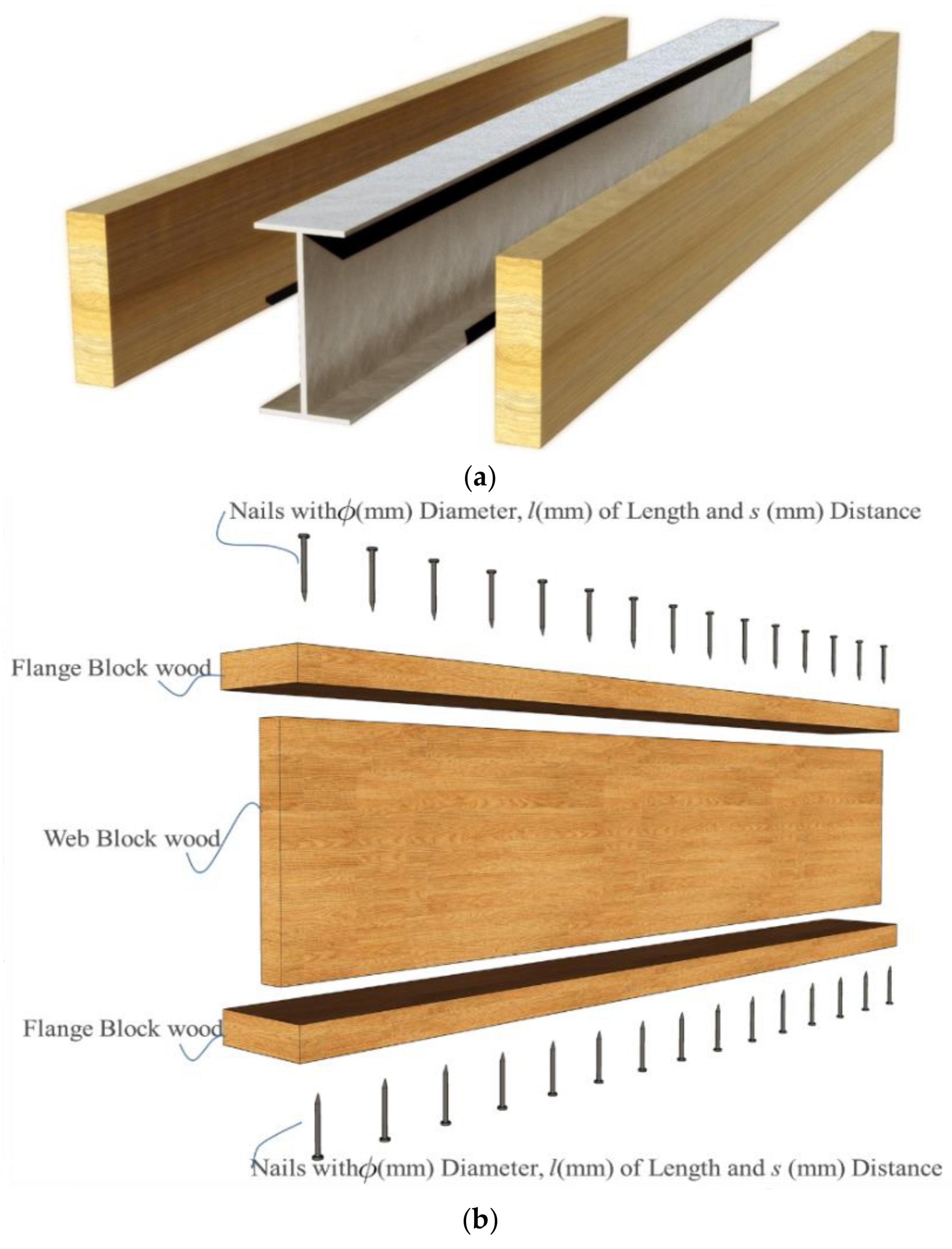
2.1. Introduction to Modeling of the Timber I-Shape Composite

A continuous load is assumed to be distributed in the timber I-shape composite, as illustrated in Figure 2a. Stress and deformation can be determined by solving the following differential equation with respect to moment M, which occurs when the assembled beam is regarded as a single beam. In Equation (1) [26], the parameter coefficients K and λ represent the properties of materials such as Young’s modulus, the cross-section, and so on, indicating the difference between the flange and the web. The method to obtain these parameter coefficients are represented in Equations (2) and (3), respectively. G is the shear resistance provided by the fasteners, and shear rigidity is considered as an equivalent web between the centers of the upper and lower flanges, as illustrated in Figure 2b. Therefore, the shear modulus is determined as shown in Equation (4). The deflection at the center of the beam can be obtained from Equation (5) by using the increased rate of rigidity determined in Equation (6). Hence, the initial stiffness can be determined using Equation (7).
d 2 M d x 2 λ 2 M + K λ 2 M t = 0 .
Mt: bending moment of external force; K and λ: parameter coefficients.
K = 1 1 + 1 + ( E A ) f c / ( E A ) f t H 2 ( E A ) f c E I .
λ = G H K E I
  • E: Young’s modulus (N/mm2).
  • G: Shear modulus per unit of equivalent web (N/mm).
  • Afc: Cross sectional of flange under compressive force (mm2).
  • Aft: Cross sectional of flange under tensile force (mm2).
  • H: Center to center height of the upper and lower flanges (mm).
  • E I : Sum of flexural rigidity of the chord members of timber I-shaped composite (N mm2).
  • Mt: Bending moment caused by external force (N mm).
  • M: Bending moment when parts of components are ignored (N mm).
  • mi: Bending moment at each individual component of timber I-shaped composite (N mm).
    G = Γ H , Γ = ( s i k i ) 1 .
  • Γ : Joint stiffness per unit between upper and lower flanges (N/mm2).
  • si: Spacing of fasteners (mm).
  • ki: Slip modulus of individual fastener (N/mm).
    δ c = α 2 ( 1 α ) 2 L 3 3 E I . 1 C c l . P
    C c l = 1 1 K + 3 K α ( 1 α ) λ 2 L 2 3 K sinh λ ( 1 α ) L . sinh λ α L α 2 ( 1 α ) 2 λ 3 L 3 . sinh λ L .
  • δ c : Deflection at the middle of beam (mm).
  • L: Span (mm).
  • Ccl: Increase rate of rigidity subject to continuous load.
    S t i f f n e s s = P δ = 48 E I × C c l L 3 .

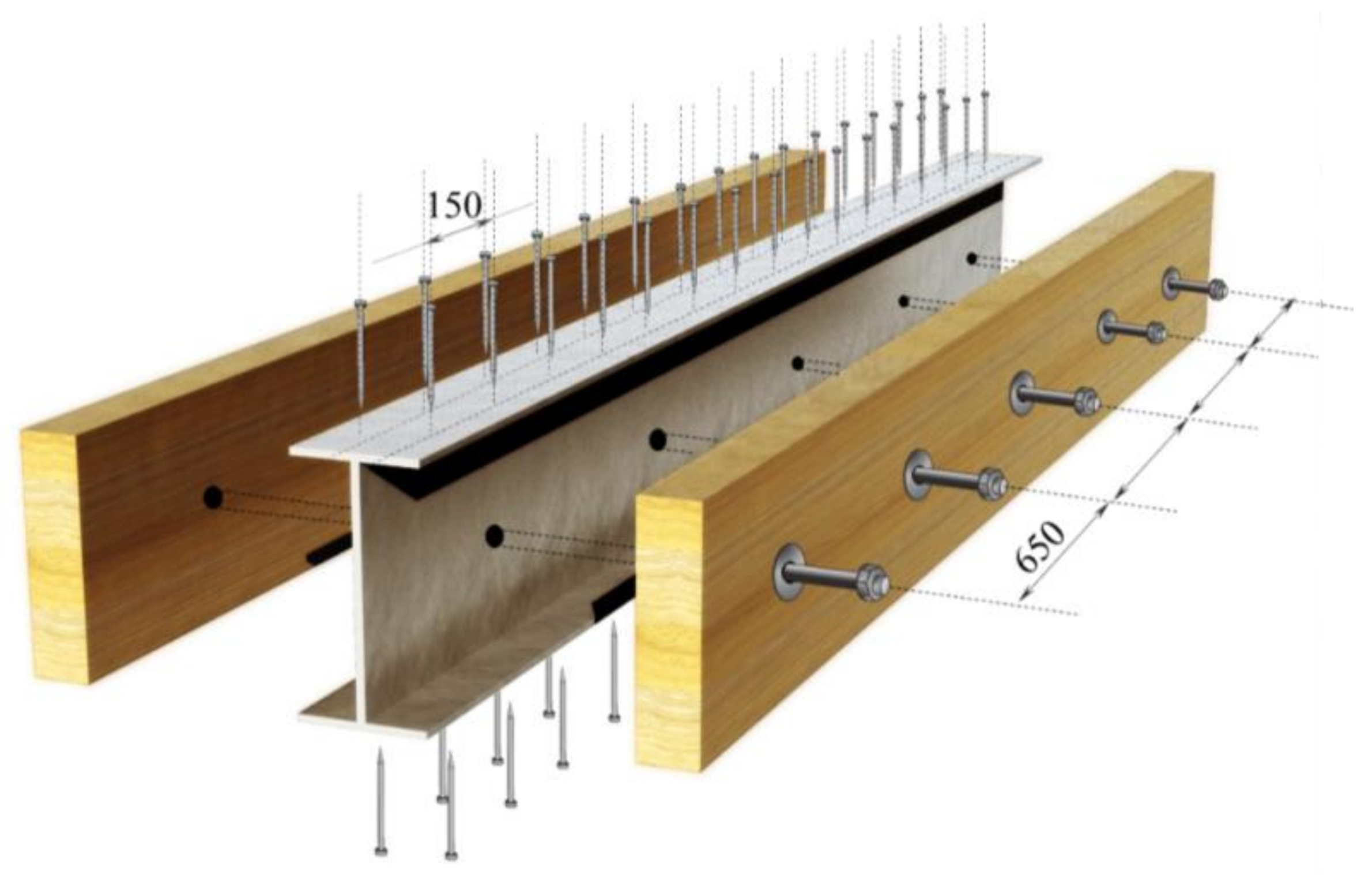
2.2. The Proposed Modeling of TSC Beam

Simulation modeling was conducted to estimate the stiffness and strength of the TSC beams with fasteners and a dowel connection. The simulation method for the timber I-shape composite was adopted in this study and improved for the estimation of the strength of TSB beams. The composition of the timber I-shape composite beam is illustrated in Figure 3a. The properties of the web, flanges, and fasteners were considered in the method to estimate stiffness. The composition of the TSC beam is shown in Figure 3b. The upper and lower flanges are mainly supported by steel, and the web consists of steel and timber. The equivalent EI of the web, consisting of steel and timber in the TSC beam, was required for the estimation. The parameter coefficients K and λ, which are provided in simulation modeling of the timber I-shape composite, take the modulus of elasticity E of the web as one value. When considering the composition of steel and timber at the web of the TSC beam, an equivalent modulus of elasticity is required to be calculated prior to the simulation being executed. Substituting equivalent E in Equations (2) and (3), these equations can be rewritten as Equations (10) and (11) for calculating the modulus of elasticity coefficients including Γ and G. For the slip coefficient Ki, which is used to describe the shear resistance of the fasteners, Kser in Equations (12) and (13) [28] are applied for the proposed simulation modeling.
E A = E s A s + E w A w
E I = E s I s + E w I w .
where
  • Es: Young’s modulus of steel (N/mm2);
  • As: Cross sectional of steel (mm2);
  • Aw: Cross-sectional of wood (mm2);
  • Is: Moment of inertia of steel (mm4);
  • Iw: Moment of inertia of wood (mm4).
    K = 1 1 + 2 H 2 ( E s A s + E w A w ) f c ( E s I s + E w I w )
    λ = G H K ( E s I s + E w I w ) .
  • Es: Young’s modulus of steel (N/mm2).
  • G: Shear stiffness per unit of web (N/mm).
  • Asfc: Cross section of steel flange under compressive force (mm2).
  • Awft: Cross section of wooden flange under tensile force (mm2).
  • H: Center to center height of the upper and lower flanges (mm).
  • ( E s I s + E w I w ) : Sum of flexural rigidity of the chord members (Nmm2).
  • Is and Iw: Moment of inertia of steel and wood, respectively.
    K s e r = ρ m 1.5 × d 0.8 30   for   nails   without   pre - drilling
    K s e r = ρ m 1.5 × d 23   for   screws
where
  • Kser: Slip modulus (N/mm);
  • ρm: Mean density of wood (kg/m3);
  • d or dc: diameter of fastener (mm).

3. Materials and Experiment

3.1. Materials

Domestic cedar, approximately 35 years old, obtained from Hsinchu County was used in experiments. According to the CNS14630 material standards code in Taiwan, water saturation was controlled to less than 15% after kiln drying. In this study, mechanical grade E80 was selected, which is the most widely used grade in the domestic market. The cross section and length of each timber member was 38 × 140 mm and 3000 mm, respectively, with a density of 393 kg/m3, which was considered common and adoptable [29]. Cold-rolled stainless steel in the form of I-shaped steel and a steel plate were used with a nominal elastic modulus of 203,000 N/mm2, according to the CNS6183 material standards code in Taiwan. The dimensions of the I-shaped steel and steel plate were 144 × 70 × 2 × 2 mm and 140 × 4 mm, respectively, with a length of 3000 mm, considering the same area of the cross section. M14 bolts were used for the dowel connection between the steel web and the wood. The steel nails CN-50 and steel screws #10-24 were used as fasteners to connect wooden members and flanges of steel members, 76.2 and 88.9 mm in length, respectively.

3.2. Experiment

The TSC beam member is illustrated in Figure 4, and the type of each beam is included in Table 1. The details of these beams are as follows: Type A is a TSC beam with the timber and steel plate connected with a dowel. Type B is a TSC beam with timber and I-shaped steel connected with a dowel (Type A and Type B were used to examine the shape factor of the steel members). Type C and Type D are TSC beams with nails and screws connected at each side of the flanges of the steel member with timber. The spacing of the fasteners (screws and nails) is 150 mm, which is the spacing referenced from the study of the built up beam [26] as well as the typical spacing used for the connection of the timber wall panel in Taiwan [8]. When a vertical load is applied to the TSC beam member, causing deflection, these fasteners connecting the steel flanges and timber are expected to provide sliding resistance between the steel and timber, improving bending resistance. However, nails and screws have different sliding resistance and hence need to be examined. Type E is a TSC beam with screws connected at each side of the flanges of the steel member with timber, at a spacing of 150 mm, as well as the dowel connection at the web with a spacing of 650 mm, at the spacing of every four nails or screws. The test on the flexural behavior of the TSC beams was conducted in accordance with the CNS 11031 standard in Taiwan. The test setup is illustrated in Figure 5. The experimental results were obtained by examining the relationship between the load (N) and deflection (mm), which were controlled by the test load with a rate of 20 N/s.

4. Results

Initial stiffness determined using the proposed simulation modeling was compared with the load–deflection relationship obtained from the experiments. The strength could be calculated using the initial stiffness at a deflection of 1/360 of the span. Thus, the applicability of the proposed simulation modeling was examined.

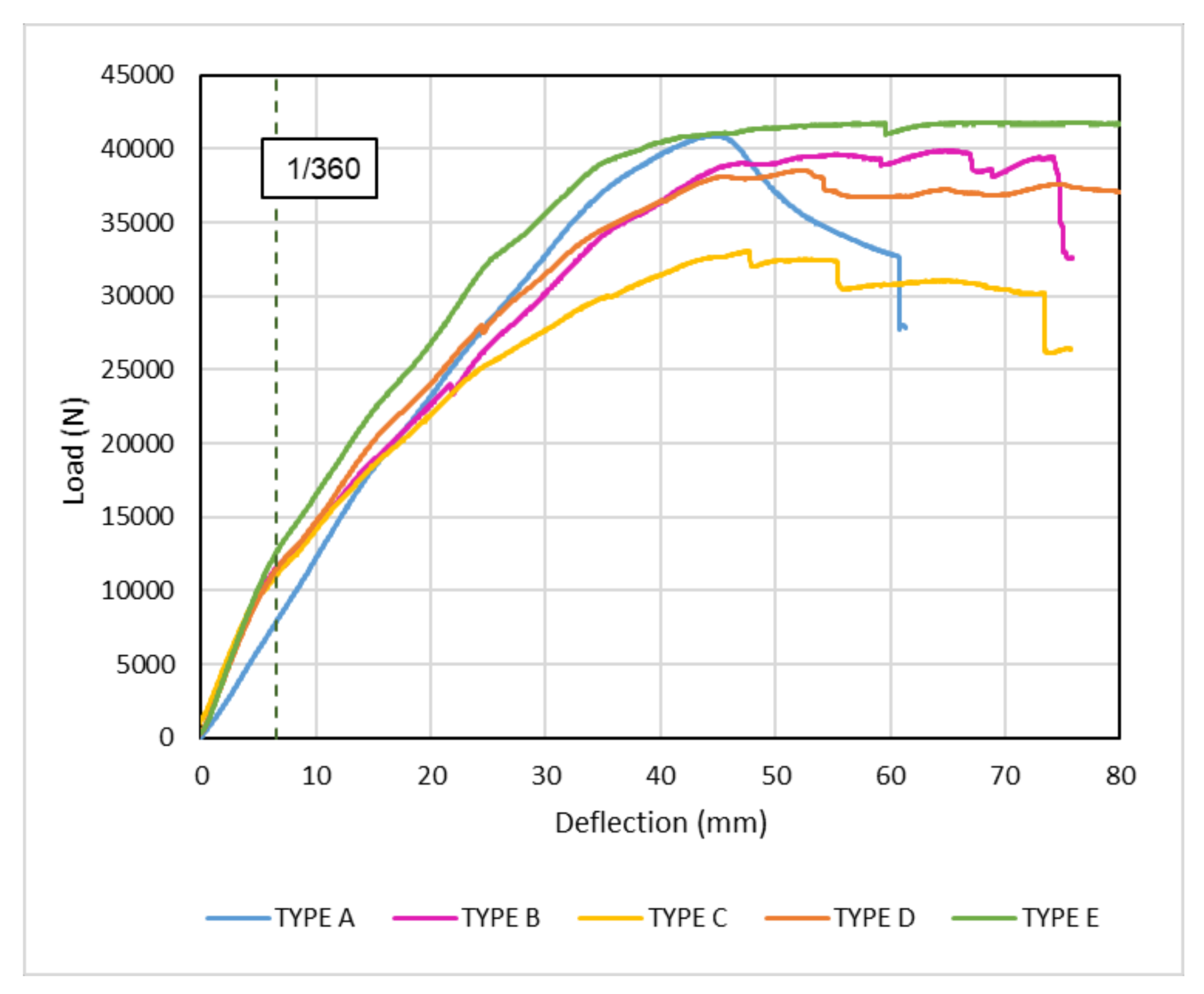
4.1. Experimental Results

The experimental results are illustrated in Figure 6. The initial stiffness of the TSC beams that had a steel plate for the steel member (Type A) was generally lower than that of the beams that had the I-shaped steel. However, the stiffness declined after deflection exceeded 1/360 of the span for most of the TSC beams that had the I-shaped steel member. Comparing the ultimate load capacity of each TSC beam, the load capacity of Type A (steel plate member) was higher than those of Type B, Type C, and Type D (I-shaped steel members) and was approximately the same with that of Type E (I-shaped steel member with a dowel connection fastened by screws).

4.2. Failure Mechanism

There were failures observed during the test, the steel member twisted for the type of TSC with steel plate attached, the buckling at the upper flange of the steel member for the type of TSC with I-shape attached, and the rupture of the timber at the lower chord after the ultimate load reached. Buckling problems can be divided into two types: local buckling and global buckling. Local buckling is the deflection of the individual plate elements relative to the corners or stiffened elements, while global buckling is the deflection of the whole section relative to the ends of the member. The steel member, twisted as shown in Figure 7a, and the buckling at the upper flange of the steel member, as shown in Figure 7b–d, are considered the local buckling.
P c r = π 2 E I ( k l ) 2 .
The compressive strength of a member subjected to an axial load is presented by the well-known Euler formulation (Equation (14)), where E is the modulus of elasticity, k is the effective length factor to account for the end-support type, and l is the length of the member, respectively. The slipping shear in the TSC beam under four-point load testing is considered the compressive load along the longitudinal direction, which results in the twisting of the steel in Type A, as shown in Figure 7a. For Type B–E specimens, it was observed that the structural behaviors were different from Type A. The major failure observed firstly was the local buckling of the steel flange. The load that was observed when local buckling of the steel flange occurred was different in each specimen; for example, the loads that caused local buckling of the steel flange were approximately 12,072 N, 9344 N, 9219 N, and 12,416 N for Types B–E, respectively. When local buckling of the steel flange occurred, the stiffness of the TSC beam declined. However, the local buckling of the flange was greatly affected by both the web depth-to-thickness ratio and the section width-to-depth ratio [30], which needs to be further studied in the future. The ultimate loads were approximately 40,898 N, 39,867 N, 33,015 N, 38,105 N, and 41,789 N for Types A–E, respectively. It was observed that the specimens without dowel connection at the web of the steel were lower than that with the dowel connection at the web of the steel. The ultimate load of the TSC beam was reached when rupture of the timber at the lower chord occurred, as shown in Figure 7b–e, and the strength of the TSC beam declined after global buckling of the steel member occurred, as shown in Figure 7f.

4.3. Comparison of Experimental and Simulation Results

The calculation results of the required coefficients are presented in Table 2. The slip coefficient Kser, joint stiffness Γ , and shear modulus G are not needed in the determination of Type A and Type B, because fasteners were not applied to the flanges of the steel member with the timber member. In Type A, no connections between flange and web are considered, so parameter coefficients K and λ are not used. Slip modulus Kser was higher in Types D and E with screws fastened than it was in Type C with nails fastened. These coefficients resulted in the difference in the joint stiffness Γ , indicating that the value when screws were applied was two times greater than the value when nails were applied. Similar results were obtained for shear modulus G. The parameter coefficient K had a stable value at 0.8, since the same materials are applied in these specimens, whereas the value of parameter coefficient λ fluctuated due to the different type of fasteners applied between steel flange and wood.
Based on the results of calculation, the initial stiffnesses of Types D and E were the same (the highest value was 2187 N/mm). The initial stiffness of Type C with nails fastened was 2005 N/mm, whereas Type B with a dowel connection and no fasteners had the lowest value (1882 N/mm). The initial stiffness of Type A is 1317 N/mm, which is determined by the composite method. The initial stiffness of the different TSC beams was compared with the experimental results, and all results are illustrated in Figure 8. The simulation modeling with the experimental results showed that the proposed simulation modeling adequately estimated the initial stiffness of TSC beams. However, it is observed that the stiffness reduced after an approximate deflection of 1/360 of the span was reached.

5. Discussion

Two shapes of steel members, namely the I-shaped steel and steel plate, were tested in this study. Type A used the steel plate, whereas the I-shaped steel was used in the remaining beams (Types B–E). Comparison between results from the experiment and the simulation modeling was made to examine the applicability of the proposed simulation modeling within the deflection of 1/360 of the span. However, it was understood that the stiffness of the TSC beams declines due to the effect of local buckling of the steel flange. Therefore, the difference between results from experiment and simulation modeling at 1/360 of the span was then compared and discussed.

5.1. Shape Factor of Steel Members

This section examines the influence of the shape factor of the steel members based on the testing results obtained for Type A and Type B, which were dowel connected with different shapes of steel. Comparing the strength at a deflection of 1/360 of the span indicated that the TSC beams with the I-shaped steel had a strength approximately 1.45 times higher than that of the TSC beam with the steel plate (8016 N and 12,072 N, respectively). In the experiments, the effect of the shape factor of the steel members was examined. The stiffness of Type B declined after a deflection of 1/360 of the span was exceeded, whereas there was no obvious declination of the stiffness for Type A, as shown in Figure 9. Thus, Type A had a higher ultimate load capacity than Type B (40,898 N and 39,867 N, respectively).
For the determination of the initial stiffness, the composite method was applied to determine the initial stiffness of Type A, and the initial stiffness of the rest of the TSC beams were determined by the proposed simulation modeling in this study. Hence, the strength obtained from the experiments and simulation modeling at a deflection of 1/360 of the span was compared to examine the reliability of the simulation modeling. The values for the experiments and simulation modeling were 8070 N and 8779 N for Type A, and 12,070 N and 12,545 N for Type B, respectively, indicating that the simulation modeling could adequately estimate the strength of TSC beams with a dowel connection with the ratio of difference less than 10%, as shown in Table 3. However, when a deflection of 1/360 of the span was exceeded, the proposed simulation modeling required modification to reflect the influence of the local bucking of the steel flange.

5.2. Influence of Dowel Connection and Fasteners

The proposed simulation modeling relies on transforming the steel web and timber into a complete member. Accordingly, equivalent EI was used for simulation modeling. The influence of a dowel connection on the steel web and timber was unclear; therefore, the relationship between the TSC beams with and without a dowel connection was examined using simulation modeling. Type D, which was fastened with screws and no dowel connection, was compared with Type E, which was fastened with screws and a dowel connection. Moreover, the strength of the TSC beams with different fasteners—nails (Type C) and screws (Type D)—was compared.
The simulation modeling indicated that no relationship existed between the TSC beams with and without a dowel connection. As such, the value of equivalent EI was the same for Type D and Type E, as shown in Table 3, resulting in the same initial stiffness of 2187 N/mm. However, the strength of these beams at a deflection of 1/360 of the span, as obtained from simulation modeling and experiments, indicated that the dowel connection had a large influence on the strength of the beams, as shown in Figure 10. The strength determined using simulation modeling was 14,578 N for Types D and E, and the strength obtained from experiments was 11,602 N and 13,442 N for Types D and E, respectively. The ratio of the difference between the strength values from the simulation modeling and experiments was 0.26 for Type D and 0.1 for Type E. Values for Type E are close, indicating that the load transmission is efficient when considering the TSC beam with a dowel connection at the web.
Two shapes of fasteners, nails and screws, were used in this study. Type C had the I-shaped steel fastened with nails, whereas Type D (with the same steel member) was fastened with screws. Studies have examined the withdrawal strength and shear strength of these fasteners, and their performance has been compared [31,32]. The results showed that the shear strength of screws was higher than that of nails, which affected the strength of the TSC beams. The strength of Type D was approximately 1.1 times higher than that of Type C at a deflection of 1/360 of the span. The experiments showed that the strength of Type D was 1.25 times higher than that of Type C. In addition, the ratio of difference between the strength values from the simulation modeling and experiments was 0.24 for Type C and 0.26 for Type D. After local buckling occurred, the steel web was affected by local–global buckling interaction. When the dowel connection was not applied in the steel web with a timber member, and there was no reinforcement added by the timber member to resist the buckling at the steel web, the thin steel web was expected to be affected by local buckling greatly, causing a higher stiffness reduction before 1/360 of the span, resulting in a higher ratio of difference for Types C (0.24) and D (0.26), compared with Types E (0.1) and B (0.04).
Types B and E had dowel connections at the steel web (Type E had additional screw fasteners). Figure 11 compares the values for strength at a deflection of 1/360 of the span between the simulation modeling and experiments. The results show that the value obtained from the simulation modeling was accurate. Table 3 compares the ratio of difference in strength values from the simulation modeling and experimental results, with 0.04 for Type B and 0.1 for Type E. These results again show the adequacy of the simulation modeling. In conclusion, by applying a dowel connection to increase the load transmission efficiency at the web, the strength that was estimated from the initial stiffness was similar to the experimental results, providing designers with reliable simulation modeling to estimate the design load for TSC beams within a deflection of 1/360 of the span. Moreover, if a TSC beam was fastened by screws and had a dowel connection, the strength at a deflection of 1/360 of the span increased by approximately 16% (simulation modeling) or 11% (experimental result).

5.3. Future Applications and Improvements

In this study, a simulation modeling adopted from a timber I-shape composite was improved and used for the determination of the initial stiffness of TSC beams assembled by local materials. The results provide local designers a method of obtaining the design strength compliant with building code in Taiwan, which is the allowable strength of the beam under the deflection of 1/360 of the span. TSC beams are expected to be applied in the retrofitting of historical wooden buildings and in the improvement of the structure stiffness for these buildings without distinct changes in wooden beams when additional load is added. Moreover, it is expected to be applied in the development of multi-storey buildings as well. Although initial stiffness can be determined, the determination of the declined stiffness after deflection reaches 1/360 of the span needs to be further studied, as does the prediction of the failure of steel members under local buckling. In general, the preliminary study for the determination of the stiffness of TSC beams is sound in this study, and more research work needs to be carried out in order to clarify the mechanism of the TSB beam.

6. Conclusions

The proposed simulation modeling, which considered the equivalent EI of the combination of steel and timber at the web of a TSC beam, can be efficiently applied to predict the initial stiffness of TSC beams assembled by local materials in Taiwan. By determining the initial stiffness using available characteristics such as the shape of the steel member and the fasteners applied with a dowel connection, it is possible to obtain a reliable result for initial analysis when the deflection is limited to 1/360 of the span. However, the specimens used for the experiment and compared with the simulation modeling were limited to one specimen per type in this study, more specimens need to be tested in order to provide further information on the variation of the results. In conclusion, the testing results in this study are summarized as follows.
Comparing the strength at a deflection of 1/360 of the span indicated that TSC beams using the I-shaped steel performed better than TSC beams using a steel plate (8016 N and 12,072 N, respectively). The difference in values can be explained by the shape factor of the steel members. The strength obtained from the simulation modeling at a deflection of 1/360 of the span was larger than that observed in the experiments by approximately 0.04 times (Type B) and 0.1 times (Type E) for TSC beams with a dowel connection at the web, which is an acceptable difference. In conclusion, it is evident that the simulation modeling reliably predicts initial stiffness and strength within a deflection of 1/360 of the span when the TSC beams have a dowel connection at the web of a steel member. Moreover, the strength of the TSC beams with a dowel connection and screw fasteners was 15% higher than comparable TSC beams without screw fasteners. If the fasteners were applied only in the flanges of the steel member with timber and without a dowel connection at the web, the differences in the strength between the simulation modeling and experiments were 24% for TSC beams fastened by nails and 26% for beams fastened by screws, indicating the efficiency of the decreased load transmission and the importance of applying a dowel at the web of a steel member.
The major failures that were observed are the twisted steel member, the buckling at the upper flange of the steel member, and the rupture of the timber at the lower chord after the ultimate load was reached. When the local buckling of the steel flange occurred, the stiffness of the TSC beam declined, and the ultimate strength of the TSC beam was reached when rupture of the timber at the lower chord occurred. Because the local buckling of the flange is greatly affected by both the web depth-to-thickness ratio and the section width-to-depth ratio, the determination of the strength at each failure stage needs to be further studied.

Acknowledgments

This research was financially supported by the Ministry of Science and Technology of Taiwan, R.O.C. under Grant no. MOST 106-2221-E-027-049- and National Taiwan University of Science and Technology.

Author Contributions

Meng-Ting Tsai conceived and designed the experiments; Truong Di Ha Le performed the experiments; Meng-Ting Tsai and Truong Di Ha Le analyzed the data; Meng-Ting Tsai contributed reagents/materials/analysis tools; Meng-Ting Tsai wrote the paper.

Conflicts of Interest

The authors declare no conflict of interest.

References

  1. Nagamura, H.; Kirino, Y.; Koshihara, M. A study of five storied timber based hybrid building for practical use (Part 1 Summary of M-Building). In Summaries of Technical Papers of Annual Meeting Architectural Institute of Japan; Architectural Institute of Japan: Tokyo, Japan, 2005. [Google Scholar]
  2. Kirino, Y.; Nagamura, H.; Koshihara, M. A study of five storied timber based hybrid building for practical use (Part 2 Summary of Structure). In Summaries of Technical Papers of Annual Meeting Architectural Institute of Japan; Architectural Institute of Japan: Tokyo, Japan, 2005. [Google Scholar]
  3. Koshihara, M.; Nagamura, H.; Isoda, H.; Kirino, Y. A study of five storied timber based hybrid building for practical use (Part 3 Properties of structural elements). In Summaries of Technical Papers of Annual Meeting Architectural Institute of Japan; Architectural Institute of Japan: Tokyo, Japan, 2005. [Google Scholar]
  4. Jerzy, J.; Tomasz, P.N. Solid timber beams strengthened with steel plates—Experimental studies. Constr. Build. Mater. 2014, 63, 81–88. [Google Scholar]
  5. Franke, S.; Franke, B.; Harte, M.A. Failure modes and reinforcement techniques for timber beams—State of the art. Constr. Build. Mater. 2015, 97, 2–13. [Google Scholar] [CrossRef]
  6. Winter, W.; Tavoussi, K.; Pixner, T.; Parada, F.R. Timber-steel-hybrid beams for multi-storey buildings. In Proceedings of the World Conference on Timber Engineering, Auckland, New Zealand, 15–19 July 2012; pp. 41–48. [Google Scholar]
  7. Tsai, M.T. Field Investigation of Retrofitting and Adaptive Reuse of Historic Wooden Buildings in Taiwan. J. Asian Archit. Build. Eng. 2017, 16, 387–394. [Google Scholar] [CrossRef]
  8. Construction and Planning Agency. Design and Construction Specifications of Wood Construction for Buildings; Construction and Planning Agency: Taipei, Taiwan, 2011. [Google Scholar]
  9. Girhammar, U.A. A simplified analysis method for composite beams with interlayer slip. Int. J. Mech. Sci. 2009, 51, 515–530. [Google Scholar] [CrossRef]
  10. Hassanieh, A.; Valipour, H.R.; Bradford, M.A. Experimental and analytical behavior of steel-timber composite connections. Constr. Build. Mater. 2016, 118, 63–75. [Google Scholar] [CrossRef]
  11. Jumaat, M.Z.; Murty, B. Yield load prediction of nailed timber joints using nail diameter and timber specific gravity. Wood Sci. Technol. 2004, 38, 599–615. [Google Scholar] [CrossRef]
  12. Sawata, K.; Yasumura, M. Estimation of yield and ultimate strengths of bolted timber joints by nonlinear analysis and yield theory. J. Wood Sci. 2003, 49, 383–391. [Google Scholar] [CrossRef]
  13. Foschi, R.O. Load-Slip Characteristics of Nails. Wood Sci. 1974, 17, 69–77. [Google Scholar]
  14. Foschi, R.O.; Bonac, T. Load-Slip Characteristics for Connections with Common Nails. Wood Sci. 1977, 9, 118–123. [Google Scholar]
  15. Kawasaki, M.; Nanami, N.; Yasumura, M. Estimating single shear capacity of screwed timber joints by yield theory. J. Struct. Constr. Eng. AIJ 2008, 73, 1797–1804. [Google Scholar] [CrossRef]
  16. Sweedan, A.M.I.; Rojob, H.N.; El-Sawy, K.M. Mechanically-fastened hybrid composites for flexural strengthening of steel beams. Thin-Walled Struct. 2014, 85, 250–261. [Google Scholar] [CrossRef]
  17. Hassanieh, A. Modelling of steel-timber composite connections: Validation of finite element model and parametric study. Eng. Struct. 2017, 138, 35–49. [Google Scholar] [CrossRef]
  18. Kreuzinger, H. Mechanically jointed beams and columns. Timber Engineering Step 1; Centrum Hout: Westeinde, The Netherlands, 1995; Volume B11, pp. 1–8. [Google Scholar]
  19. Ceccotti, A. Timber-concrete composite structures. Timber Engineering Step 2; Centrum Hout: Westeinde, The Netherlands, 1995; Volume E13, pp. 1–12. [Google Scholar]
  20. Fernandez-Cabo, J.L.; Fernandez-Lavandera, J.; Diez-Barra, R.; Avila-Jalvo, J.M. Timber composite beams with a discrete connection system. Proc. Inst. Civ. Eng. 2013, 166, 57–72. [Google Scholar] [CrossRef]
  21. Bajzecerová, V. Bending Stiffness of CLT-Concrete Composite Members—Comparison of Simplified Calculation Methods. Procedia Eng. 2017, 190, 15–20. [Google Scholar] [CrossRef]
  22. Kobayashi, K.; Inayama, M.; Ando, N. New estimation method on stiffness and strength of single shear screw joints with structural panels. J. Struct. Constr. Eng. AIJ 2007, 622, 121–128. [Google Scholar] [CrossRef]
  23. Fukuyama, H. Proposal of analytical models of wooden dowel shear joint single shear joint with slender-type round dowels. J. Struct. Constr. Eng. AIJ 2007, 622, 129–136. [Google Scholar] [CrossRef]
  24. Fukuyama, H. Calculation model and yield process of single shear joint with wood dowel of various slendernesses. J. Struct. Constr. Eng. AIJ 2008, 73, 803–810. [Google Scholar] [CrossRef]
  25. Noguchi, M.; Komatsu, K. A new method for estimating stiffness and strength in bolted timber-to-timber joints and its verification by experiments (II): Bolted cross-lapped beam to column joints. J. Wood Sci. 2004, 50, 391–399. [Google Scholar] [CrossRef]
  26. Kamachi, K.; Inayama, M.; Inoue, M. Design method for the built-up beams. J. Struct. Constr. Eng. AIJ 2009, 74, 601–700. [Google Scholar] [CrossRef]
  27. Japan Architecture Society. Design Manual of Engineering Timber Joints; Japan Architecture Society: Tokyo, Japan, 2009. [Google Scholar]
  28. European Committee for Standardization. Eurocode 5: Design of Timber Structure; BSI: Brussels, Belgium, 1994. [Google Scholar]
  29. Yang, J.C.; Lee, C.H.; Chiu, C.M. Genetic Variation of Wood Density in Luanta Fir Tested In Central Taiwan. Wood Fiber Sci. 2001, 33, 486–491. [Google Scholar]
  30. Ragheb, W.F. Local buckling of welded steel I-beams considering flange–web interaction. Thin-Walled Struct. 2015, 97, 241–249. [Google Scholar] [CrossRef]
  31. Alpe, A. Determination of Screw and Nail Withdrawal Resistance of Some Important Wood Species. Int. J. Mol. Sci. 2008, 9, 626–637. [Google Scholar]
  32. Bues, C.T.; Schulz, H.; Eichenseer, F. Investigation of the Pull-out Resistance of Nails and Screws in Pine Wood. Holz Roh Werkst. 1987, 45, 514. [Google Scholar]
Figure 1. Illustration of (a) the TSC beam and (b) the timber I-shape composite beam.
Sustainability 10 01220 g001
Figure 2. Concept for simulation modeling. (a) Assumption of stress distribution for sections of each element. (b) Determination of shear modulus based on slip modulus of individual fasteners [27].
Sustainability 10 01220 g002
Figure 3. (a) Timber I-shape composite beam; (b) TSC beam.
Sustainability 10 01220 g003
Figure 4. TSC beam with fasteners and dowel connection (unit: mm).
Sustainability 10 01220 g004
Figure 5. Test setup (unit: mm).
Sustainability 10 01220 g005
Figure 6. Load-deflection relationship for each beam.
Sustainability 10 01220 g006
Figure 7. Failure modes. (a) Local buckling of the steel plate in Type A. (b) Failure mode of Type B. (c) Failure mode of Type C. (d) Failure mode of Type D. (e) Failure of global buckling in Type E. (f) Global buckling in Type E.
Sustainability 10 01220 g007
Figure 8. Experimental results and simulation modeling of initial stiffness. (a) Type A. (b) Type B. (c) Type C. (d) Type D. (e) Type E.
Sustainability 10 01220 g008
Figure 9. Influences of shape factor.
Sustainability 10 01220 g009
Figure 10. TSC beams with/without dowel connection and different fasteners.
Sustainability 10 01220 g010
Figure 11. TSC beams with dowel connections with/without screw fasteners.
Sustainability 10 01220 g011
Table 1. Testing beams (unit: mm).
Sustainability 10 01220 i001 Sustainability 10 01220 i002 Sustainability 10 01220 i003 Sustainability 10 01220 i004 Sustainability 10 01220 i005
TYPE ATYPE BTYPE CTYPE DTYPE E
Steel plate with dowel connectionI-shaped steel with dowel connectionI-shaped steel with nails fastenedI-shaped steel with screws fastenedI-shaped steel with dowel connection and screws fastened
Table 2. Coefficients required for determining initial stiffness.
Types of CoefficientsType AType BType CType DType E
Slip modulus Kser (N/mm)--1.573.13.1
Joint stiffness Γ (N/mm2)--5.210.310.3
Shear modulus G (N/rad)--73816421642
E I (Nmm2)32.4 × 101052.5 × 101052.5 × 101052.5 × 101052.5 × 1010
Parameter coefficient K-0.800.800.800.80
Parameter coefficient λ (mm−1)-0.12 × 10−30.5 × 10−30.71 × 10−31.0 × 10−3
Increased rate Ccl-11.11.21.2
Initial Stiffness (N/mm)13171882200521872187
Table 3. Initial stiffness, strength, and ratio of difference.
Type of SpecimensInitial Stiffness (N/mm)Strength at Deflection 1/360 of the Span (N)Ratio of Difference (Ls-Le)/Le
Simulation Value LsExperimental Value Le
Type A1317877980700.09
Type B188212,54512,0720.04
Type C200513,36510,2030.24
Type D218714,57811,6020.26
Type E218714,57813,4420.10

