1. Introduction
Caisson technology as a method of port construction has come a long way since it was first used by Julius Caesar in the siege of Brindisi [
1] and its display as a construction method in
De Architectura by Vitruvius [
2]. This method was consolidated in times of the Roman Empire with the construction of the port of Ostia (Portus) using
opus caementitium caissons and hulls of sunken ships [
3].
The real boom in this system did not come about until the Renaissance. Literature documenting the growing use of this technology such as the Treatise of Juanelo Turriano [
4], the books of Taccola [
5], and the technical treatises of the time as summarized in the article entitled “From Julius Caesar to composite materials” [
6].
In the Industrial Revolution, timber gave way to iron such as in the ports of Bilbao [
7] and Madras [
8]. The use of concrete began later and increasingly larger sized caissons were built faster.
The 20th century saw these concrete caissons expand the world over. Both types and construction methods evolved and these caissons were built in dry docks or on floating docks.
Theoretical maritime engineering is still evolving with better knowledge of the phenomena and increasingly more potent numerical models leading to the conception of new types of breakwaters and, in consequence, of caissons. In many cases, these new forms call for new construction processes and/or new materials. Some of these forms are still too advanced to be built in terms of economic viability.
In addition, concern for Sustainable Development requires more complex forms because of the implementation of additional functions in breakwaters (production of wave energy or dissipation of its energy to buffer it). This opens up a field of new requirements in the world of caissons for which current construction systems are not always adapted.
Apart from lowering costs in the use of high performance materials (composite materials), introducing the circular economy into the equation allows for an advantage to be taken regarding materials which, otherwise, would end up in a rubbish dump. In this way, it is an adaptation toward new sustainability policies and advance towards more complex structures.
The intention of this article is to make a balance of the situation this technique finds itself at this time in order to envisage the needs for using both new materials and increasingly more complex forms caissons and their manufacture in an industrialized and economically viable manner call for.
Caissons need to evolve to be adapted to technology demands. Composite materials are suitable to new scopes, but their high cost requires their usefulness justification. We, therefore, propose that next step in caisson shapes is developed with recycled composites.
Its feasibility is justified considering technical and environmental issues and a wider approach of the economic analysis throughout the life cycle assessment.
Comparison of different solutions would be easier using finite elements for structural calculations and then, making a multi-criteria analysis considering their costs and an environmental product declaration will show us the complete picture.
This contribution shows where the technology comes from, which are tools and restrictions, and which is the path and why.
2. The Industrialization of Caisson Construction: Concrete Caissons
2.1. Naval Background
Caisson technology has been closely linked to the naval world. At the end of the 19th century, the growing needs for vessel construction and maintenance required enormous floating docks to repair warships. In 1896 [
9], there were 116 floating docks. The longest measured one was 283 m in the port of Birkenhead in Great Britain.
The different types are described in floating docks [
10] among which the new one called “One sided dock: Depositing type” was used for the first time by the Russian Admiralty in Nicolaieff in 1876 with obvious similarities to those used in building caissons in the Japanese port of Kobe and the West Barcelona Breakwater [
10,
11,
12].
The largest floating dock mentioned has a hoisting capacity of 18,000 tons with a length of 525 feet (160 m) in New Orleans.
Other solutions currently exist by providing more versatility to shipyards when taking advantage of their areas. Syncrolift, which is a system for hoisting large loads using rails and hydraulic jacks, was invented in 1954 [
13,
14]. This system allows enormously large vessels to be moved and is a great saving of space for shipyards apart from avoiding the construction of high cost, slower dry docks. Examples exist with a maximum displacement capacity of 23,320 tons and a length of 188 m.
The largest caissons used by this system are those of the
Consorzio Venezia Nuova for which a 70 m long, 50 m wide Syncrolift platform is used for moving caissons weighing 22,500 tons employed in the Malamocco barrier protecting the Venice lagoon [
15].
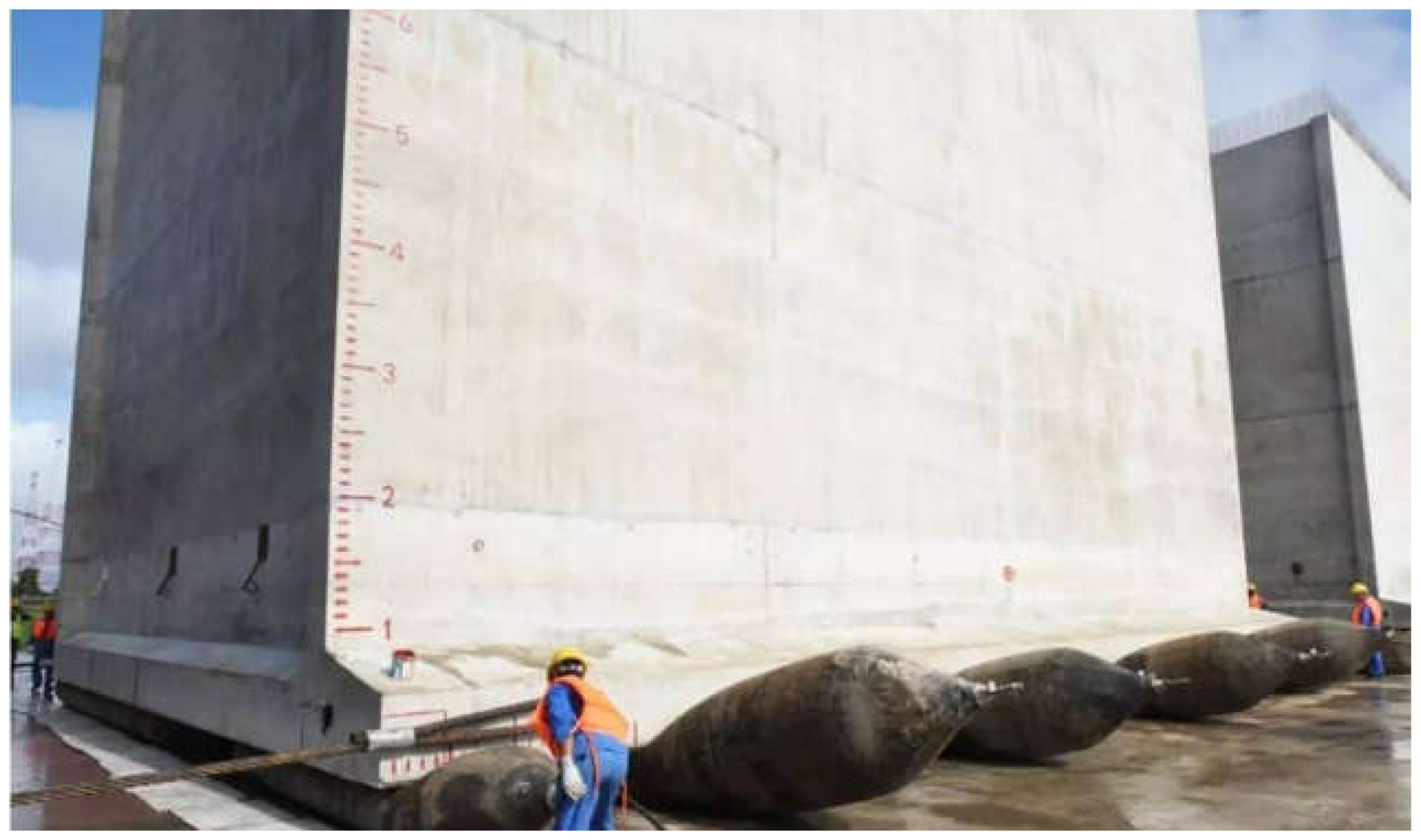
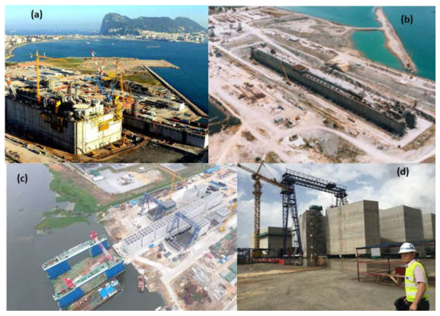
In works for extending the Autonomous Port of Abidjan by the Chinese CHEC company, the land built caissons are moved by a system of inflatable pneumatic rollers similar to how beach stranded ships were built on beds of tree trunks centuries ago (
Figure 1).
2.2. Concrete Curing
Concrete curing plays a very important role in making caissons since the nature of the water used may be a determining factor between choosing one construction process or another.
Numerous tests have allowed regulations to be minutely examined in some countries where sea water is used at least for curing reinforced concrete, which allows floating docks to be used [
17,
18]. Current conditioning factors as occurring are briefly explained.
First, the water/cement ratio oscillates, according to the different sets of regulations, between 0.4 and 0.5 and will vary depending on environmental aggressiveness. The cement content shall be higher than 300 kg/m
3 and not exceed 500 kg/m
3 [
19].
The concrete coating is also important. It should range from 50 mm to the more restrictive 75 mm as promoted by British Standards but as to the control of corrosion, the limitation of chlorides lower than 0.1% [
19] is more important.
The initial strength of seawater cured concrete is higher than that sweet water cured, which is favored by the water’s temperature and presence of calcium chloride, but, in the long term, it becomes equal or diminishes [
17,
20,
21].
However, the determining factor is the presence of the chloride ion (Cl
−), which has to be controlled. Limitations in the previously mentioned parameters allow for the concrete’s lesser permeability and, therefore, greater protection of reinforcements to corrosion. This is a factor which, in the long term, will not be influenced by concrete cured with sweet or sea water. To this effect, tests carried out checking the structure’s permanent exposure to sea water will be a determining factor and the effect of curing will be residual [
22].
Countries with a major tradition in caisson construction such as Italy, Japan, and Spain are more open to these theories and, therefore, to the use of floating docks [
23].
On the other hand, other countries continue with curing restrictions and still require curing of up to 28 days with sweet water. This is why, inevitably, the construction process has to be developed dry [
24].
2.3. Evolution of the Construction in the 20th Century
Following positive experiments with metal caissons in the ports of Bizerta, Zeebrugge, and Bilbao [
8,
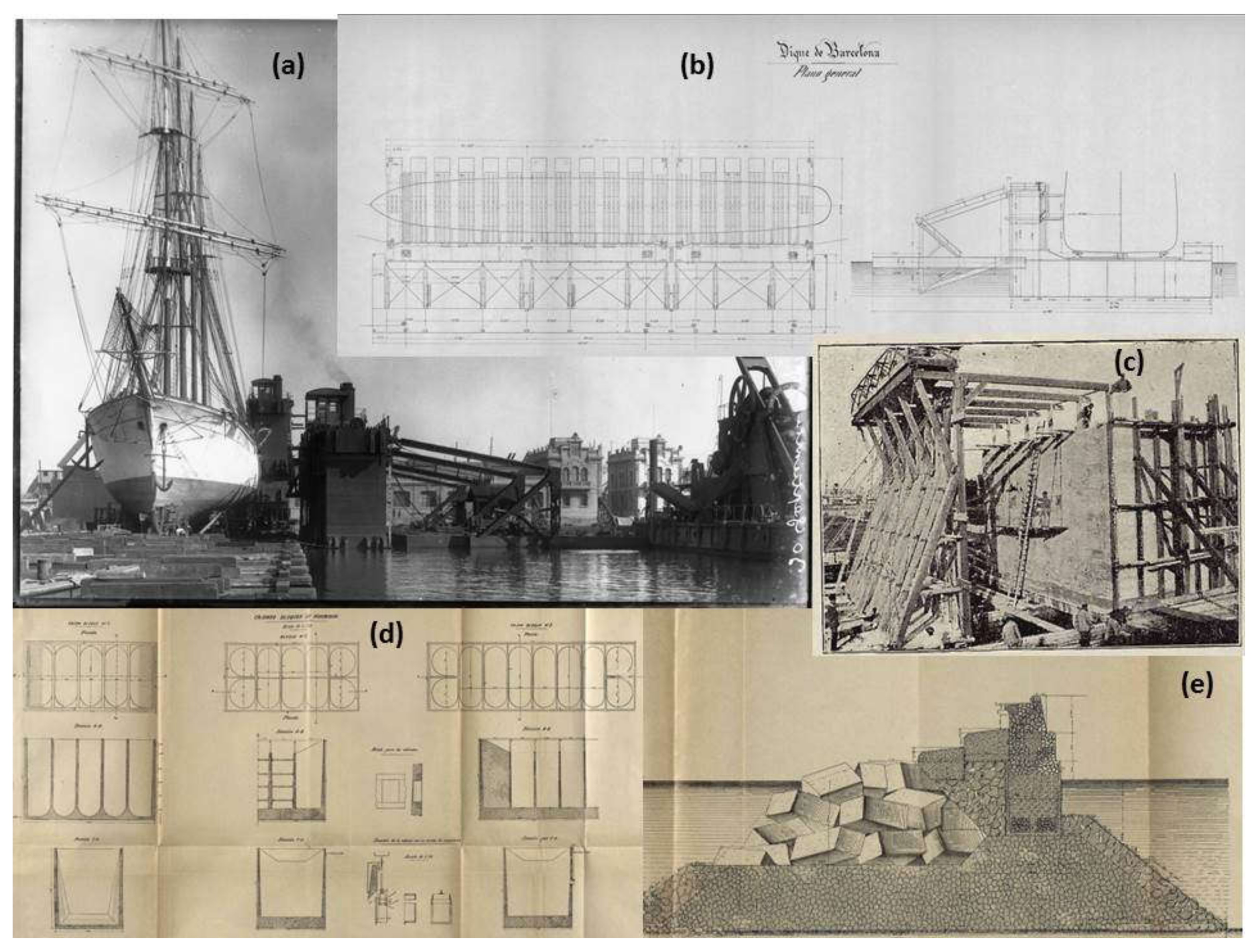
25], concrete was used in the port of Barcelona to solve construction problems arising in the extension to the East Breakwater. The first four experimental caissons were constructed in 1905 and, convinced they were ideal and cost less than the usual solutions, the process was industrialized [
26]. The works extended over several years and the west floating dock in the Port of Barcelona was used. The initial size was 18.60 x 6 and 7 m high [
26] and caissons of up to 25 m long were built [
27].
Figure 2 shows us caissons and floating dock.
Very innovating at that time, this construction process was presented on an international scale at the 10th Congress of Navigation held in Milan in 1905 and at the 11th Congress of Navigation in Saint Petersburg in 1908 [
8,
27,
28].
In the port of Kobe, Japan, on the other side of the planet almost at the same time and with a very similar floating dock, concrete trapezoidal caissons were being built whose dimensions were somewhat larger measuring 35.85 m long, maximum depth of 12.65 m, and an average beam at the base of 10.80 m. They were made in three months [
11].
In 1929, an award was made for building quays in the Merwehaven dock basin using concrete caissons (rectangular and trapezoidal) in the port of Rotterdam [
31]. We must mention the prefabrication area provided for by a system of floating concrete platforms for the first phases (slab and five phases of 2.85 m in concreting height,
Figure 3). Approximately one 40.00 m long caisson per week was produced [
31].
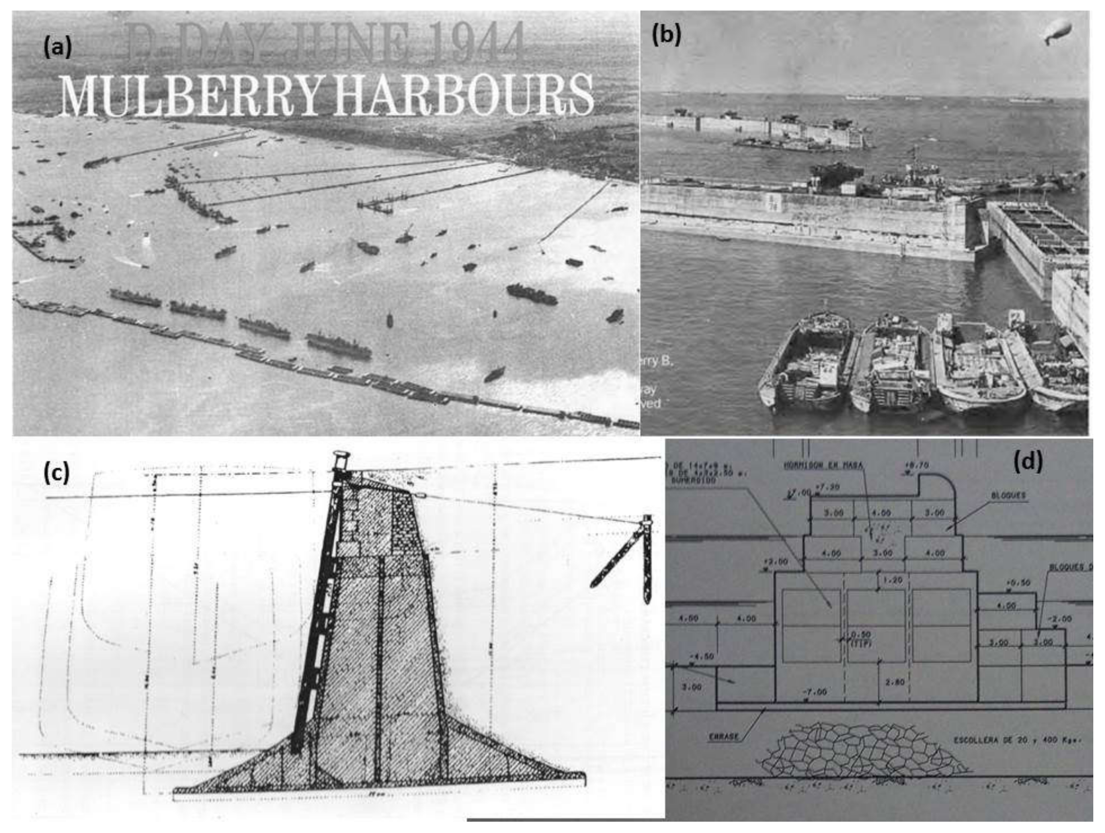
The Phoenix or Mulberry floating concrete harbors used in the Normandy landings in June, 1944, were a great advance in dimensioning floating concrete docks (
Figure 4). They were built in a dry dock and were up to 60.00 m in length and 20.00 m in depth and were towed from England across the English Channel. The lack of iron in wartime led to concrete being used and this was an enormous promotion for caissons [
32].
This technology started in Italy in 1925 to 1927 with some minor works in the ports of Naples, Genoa, and Capri. References also appear in Alghero (1915) and Civitavecchia (1931–1936), but this technology was really developed following the Second World War [
23,
35].
Despite this, there is the striking example of the port of Genoa in which 42 caissons were built in 1938 but could not be installed in their final emplacement when the Second World War commenced. These caissons were refloated and recovered after the conflict in an optimum condition and were used to make the filling for the Genoa airport [
35].
A start with concrete caissons was made in the port of Kobe in Japan at the beginning of the 20th century. This technology has continued to be used in recent times and a large number of solutions were developed. In 1994, there were 800 km of breakwaters in this country, which were mostly built by the caisson system. This is associated with professors such as Hiroi, Mitsoyashu, Tanimoto, Goda, or Takahashi [
36].
Kobe was followed by the island breakwater of Otaru (1912–1917). Wholly filled with concrete to achieve greater durability and stability, this breakwater has lasted until our time. The fill technique evolved to achieve rapidity and savings and concrete blocks were used in the port of Onahama to fill the caissons [
37]. Concrete was the fill traditionally used before the end of the Second World War but changed to granular materials and then sand fills in the caissons of the port of Yokohama, built in the period from 1928 to 1943. Although initially sand was used only in areas with low wave action, after World War Two, this practice now became usual in caisson fills [
34,
35,
37,
38].
Caisson technology is extensively used in Japan and breakwaters of this type are built for protection from Tsunamis [
38]. To this effect, the Ofunato breakwater was, at the time, the deepest at 30.00 m. Today, Kamaishi breakwater is 60.00 m in depth and is the deepest yet.
Within Japanese experiences, the port of Hedono’s singular caissons are found to be the widest built, with 38-m beams. The longest is the temporary breakwater for the port of Kochi, which is 100.00 m long [
38]. These lengths open up a further stage in breakwater design since, as from certain caisson lengths, they gain in stability when receiving a mean wave action force when waves are obliquely incident. “The long caisson is expected to receive a reduced mean wave force per unit length for obliquely incident waves because of the phase difference along the extension” [
23,
36,
38].
In Spain, caissons in the deepest docks have been built at Punta Lucero in the port of Bilbao, by using caissons of 39 m depth and a breakwater with foundations at −32.00 m.
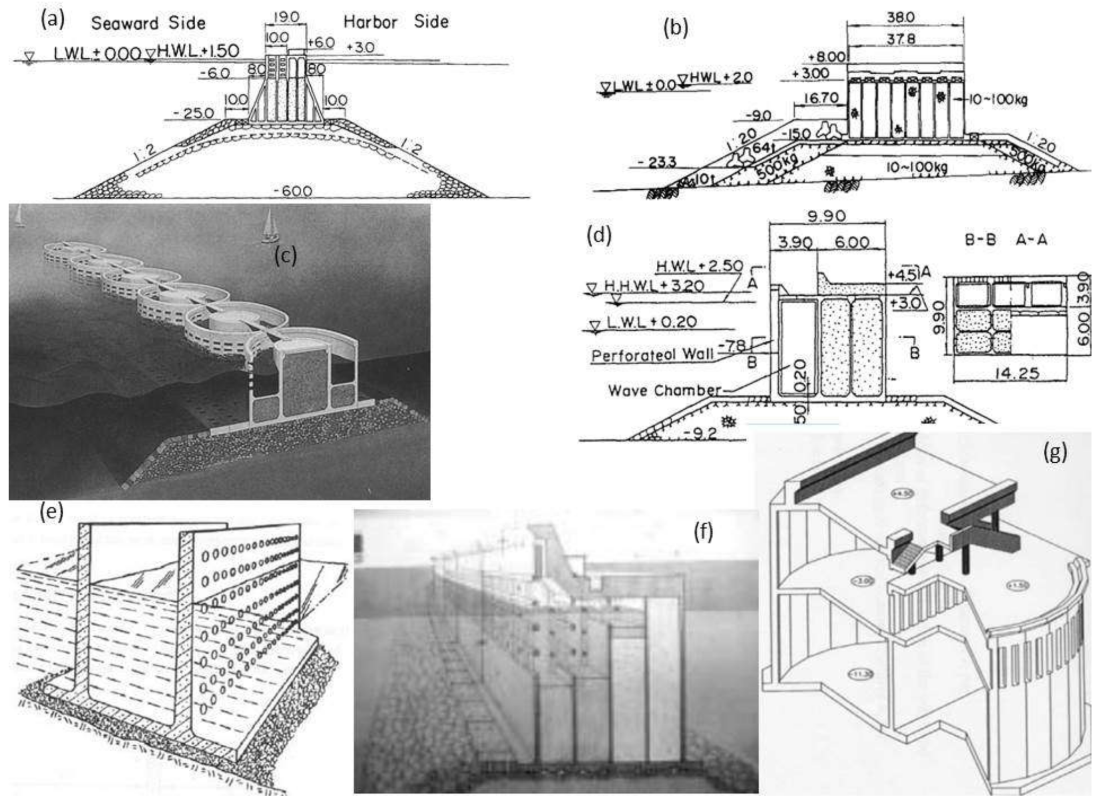
As mentioned earlier, caisson types have evolved, which leads us to more complex form designs and optimizing the use of materials. On the other hand, the problems of vertical breakwaters such as wave reflection may be attenuated.
With forms such as the trapezoidal caisson, caissons with a curved crown, or cylindrical caissons, greater stability of the structure is due to the actual effect of waves on the caisson´s form and, therefore, lighter or less stressed caissons [
33].
The latest trends are directed towards perforated or non-reflecting caissons. They began with Jarlan’s design in 1961 where, initially, a reduction in the structure was the aim since it had been proven that turbulence led to caissons receiving smaller waves apart from the effect of a reduction in reflected wave action [
38]. The system was first practically applied at Comeau Bay (Canada). Both construction difficulties and the influence of the wave period were demonstrated in all cases.
It is important to differentiate between caissons for the manner in which they are to be used since they are sized differently if their purpose is to attenuate reflection at a quay or to diminish the wave effect on the structure in open water.
This technique rapidly spread in Japan where there are a number of examples until arriving at dual perforated cylindrical caissons (
Figure 5).
Through the PROVERBS program in Europe, pressure meters were installed in two breakwaters finished in 1992 (Porto Torres in Italy and Dieppe in France,
Figure 6) in order to compare the theoretical analyses and validate the hypotheses (
Figure 5). A reduction of 30% in run-up was recorded in the case of Porto Torres in the perforated face as against that recorded in the continuous vertical face [
39].
One of the conclusions of these analyses is that choosing a caisson with a single chamber (OCS) or multiple chambers (MSC) will be conditioned by the construction process chosen.
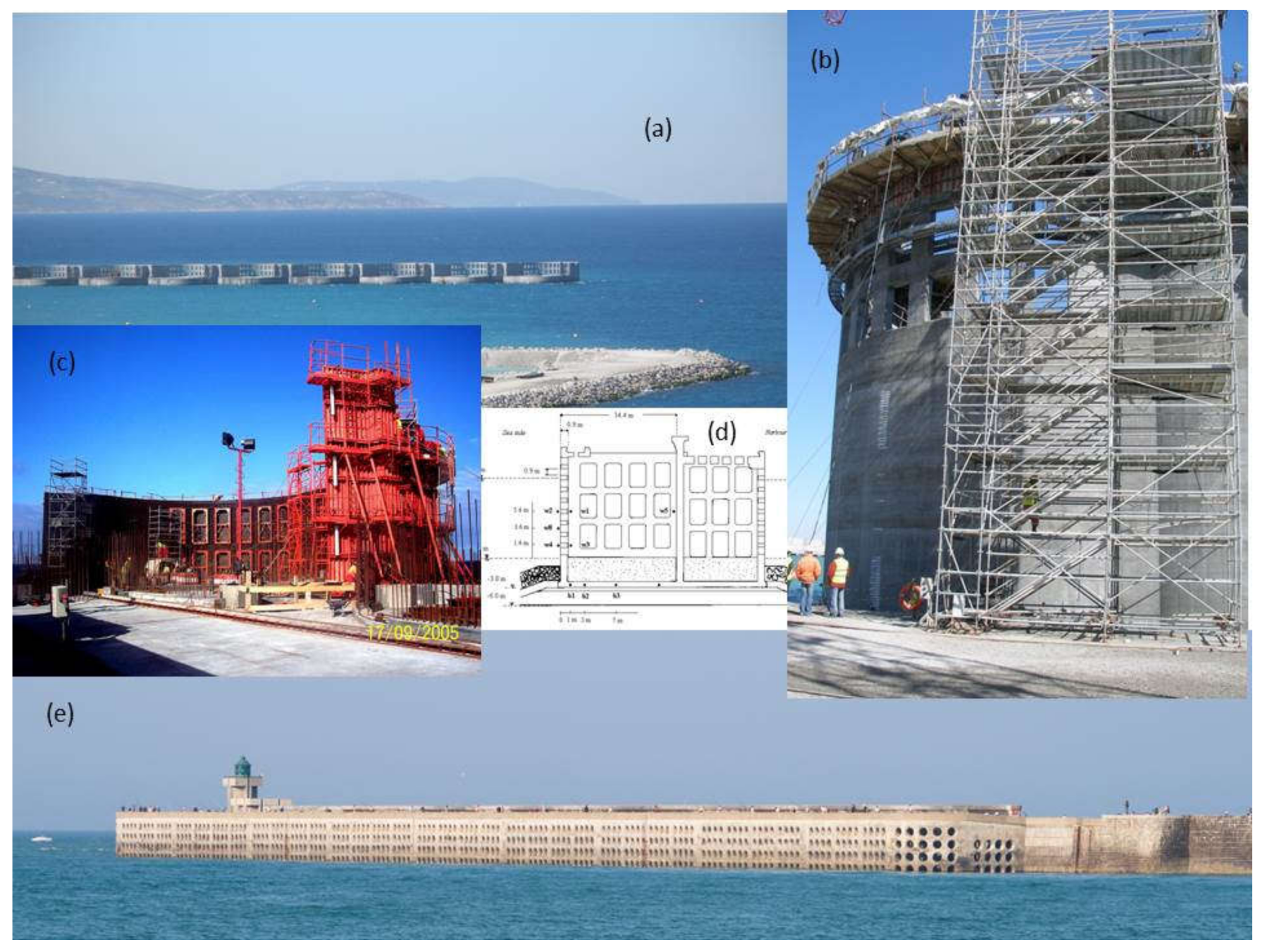
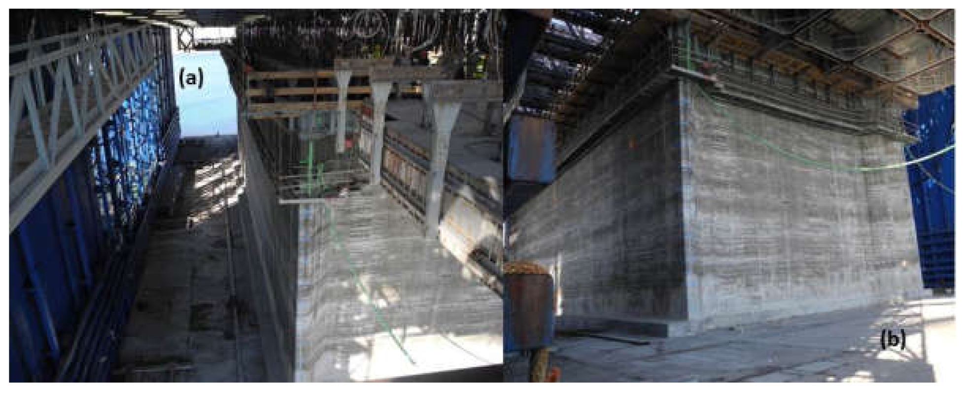
Caissons with windows have been made in Spain adapting both the form of the caisson and the windows to allow the floating dock’s formwork to slide or to finish the caisson and its windows with the caisson anchored next to the quay. This was the procedure in Castellón or Tarragona as well as constructing caissons in the port of Tangiers in 1997 (
Figure 6).
A walkway breakwater was built in the port of Beirut (Lebanon, 2004) using caissons of this type with a dual, interior dissipation chamber (ARC).
The floating dock technique will be used in the port of Monaco up to a certain level and the caisson cells will be finished next to the quay [
45] (
Figure 7).
In short, caisson forms keep on evolving due to the advance in investigation work and increasingly more powerful calculation tools. Caisson construction technology must also evolve to adapt to the new forms conceived.
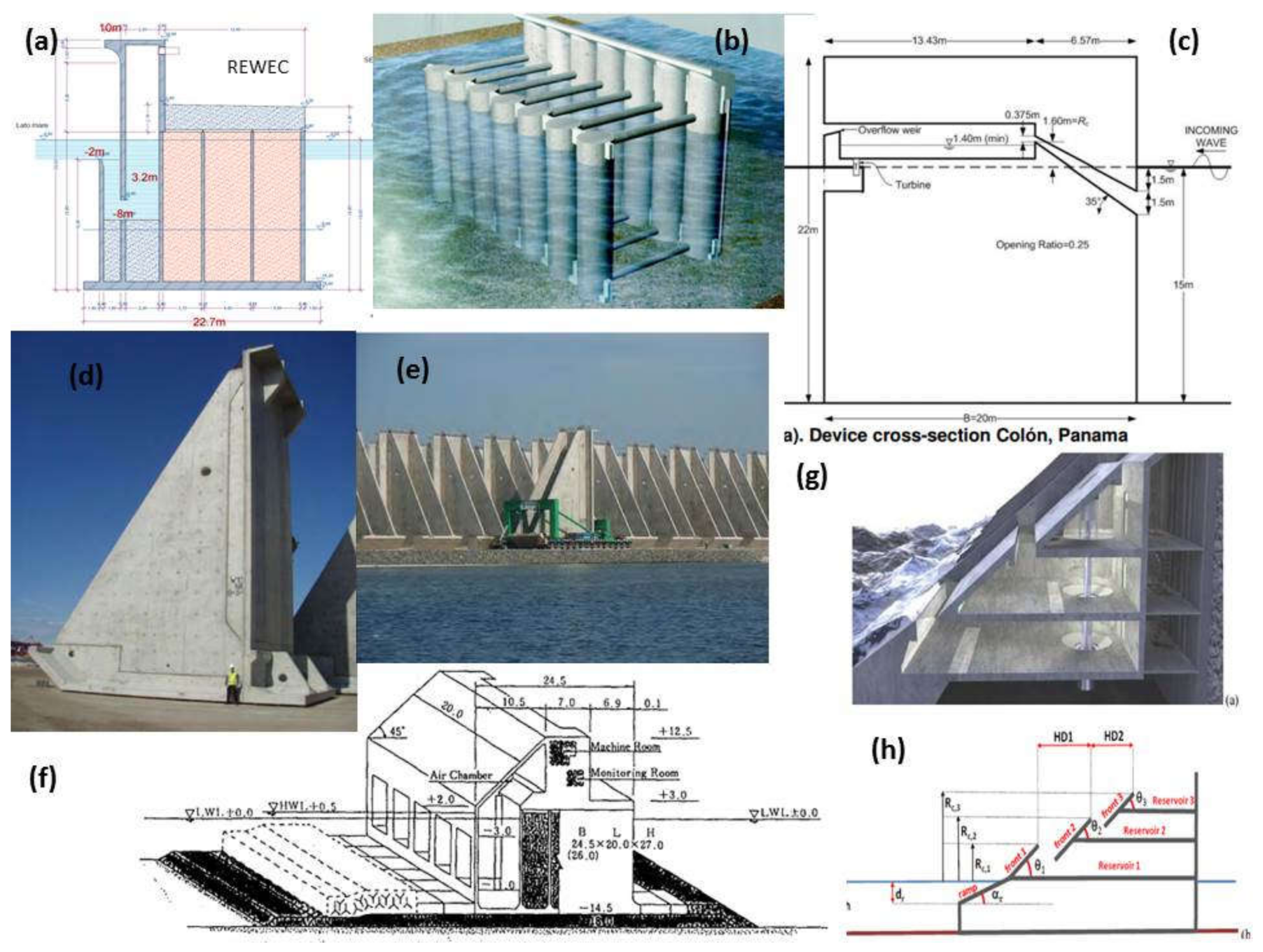
Figure 12 shows perforated cylindrical caissons designed to be built on a floating dock by a sliding form work such as an example of a new structure only existing in theory [
47].
In general, as Miguel Vázquez [
39] notes in his Thesis, the evolution of perforated caissons calls for a relatively greater width of the chamber (B/L) to diminish incident wave action reflection and it is, therefore, necessary to review construction processes beyond floating docks and to be more versatile than current drying methods.
Off-shore wind farms have a crescent importance in the world and some experiences with caissons have been developed [
48,
49,
50]. Since the foundation represents a big amount of the investment (35%) [
51] and considering that it is a very important element in the structure, that opens up another field for caisson technology.
2.4. Construction with Floating Dock
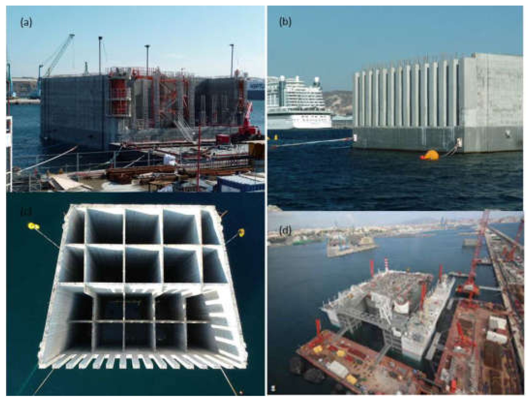
The increase in merchant ship sizes has led to increasing the necessary draught and, therefore, caisson depths. The length and beam of the latter have also increased through stability requirements.
Large construction companies have, therefore, had to take on increasingly larger floating docks allowing for rapid, industrialized construction [
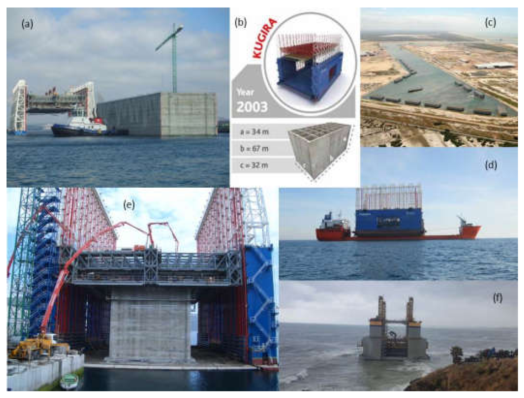
52]. In the case of Acciona with the Kugira, caissons can be built with maximum dimensions of 67 m in length, 32 m in beam, and 34 m in depth (
Figure 8). The largest built up to now measures 66.85 m in length, 24.6 m beam, and 34 m in depth at Isla Verde in Algeciras [
53].
At the beginning of the century, floating docks were used on which to build them and dry, like seen in
Figure 9 with a “small” caisson built with Kugira dry dock. With caisson sizes increasing, it became more and more necessary to have floating docks of greater dimensions or to evolve the techniques as was, in fact, achieved. This occurs in the case of the port of Rotterdam in 1929 [
31] (
Figure 3). In other cases, a platform was used where dry construction commenced and, later, the caisson was sunk and construction continued with the caisson moored to a quay and floating.
Successive evolutions have led to the modern series caisson construction using a floating dock provided with a sliding form work system called an umbrella. This technique became possible due to the evolution in materials and the study of concrete [
53].
The rate of sliding may be in the order of 5 m per day and a caisson may be built in approximately 10 days.
This caisson would be sunk with the dock as its depth grew and its weight increased. Hence, thereon construction would continue while keeping its freeboard constant.
In Spain, a large part of ports built since the 1980s has used this technology, building caissons of up to 14,000 tons.
The use of caissons and their types are still evolving and floating dock construction must adapt to them.
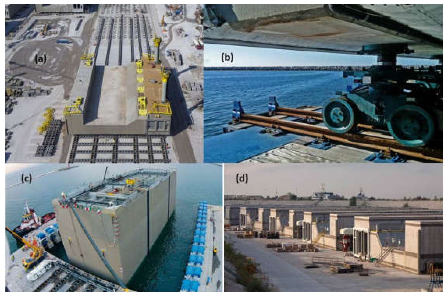
The alternative to building caissons on floating platforms is to use dry construction (whether in dry dock or on an esplanade). This makes the construction system far different to the floating dock method (
Figure 10a,b).
They are built like any structure on land with diverse stages of formwork or with climbing formwork.
This is still the only viable system in many places since regulations do not, under any concept, authorize curing with sea water. The floating dock system is, therefore, automatically discarded: in the sliding process for the port of Durban and keeping to British Standards and South African standards: “Under no circumstance shall seawater be used for mixing or curing concrete” [
24]. In other cases, the excessive size of the caisson or its form, which does not allow sliding, lead to this system being used.
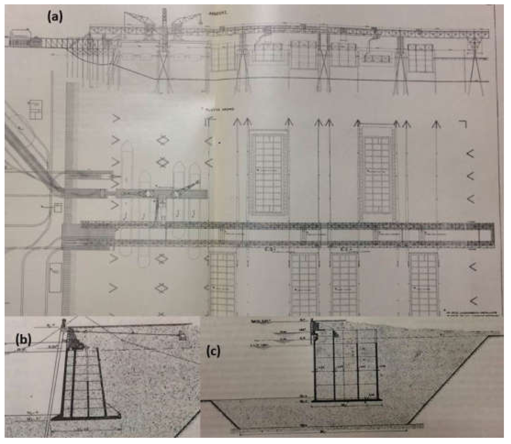
In the extension to the port of Abidjan in the Ivory Coast, the Chinese CHEC company is dry constructing caissons to launch them afterwards with the aid of a floating dock (
Figure 10c,d).
In the case of caissons built by Bouygues in the port of Tangiers [
41], where one part was dry constructed, they were launched by means of a keel block (Syncrolift) in order to finish the anti-reflective chambers with the caisson in the water.
Large sized caissons are also dry constructed. This is the case of the floating caisson for Monaco La Condamine built by Dragados and FCC with a length of 352.00 m, 28.00 m beam, and a depth of 19.00 m. It also has a 163,000 ton displacement [
55]. The same happens with the prestressed concrete caisson for Gas LNG called Adriatic built by Acciona with 180.00 m in length, 88.00 m beam, and 47.00 m in depth [
54]. They were both dry dock constructed in Algeciras.
The caissons for the retaining wall of the Venetian lagoon are also large sized and highly complex using the MOSE (
MOdulo Sperimentale Elettromeccanico), earmarked to housing flood containing gates. The largest is 60 m long, 48.3 m beam, and 11.5 m high [
15,
56] (
Figure 11).
2.5. Pros and Cons of Each System
Throughout the document, particularities of different systems have been exposed and it is useful to be able to compare them at a glance by analyzing pros and cons. The choice of method statement depends on many elements but, many of them, could be found in
Table 1.
Furthermore, this table could allow the making of a multi-criteria analysis based on quantitative parameters (the ones considered in this table), comparing numerically each one of the solutions. Decision-making will then be easier and more accurate.
2.6. Historical Analogies
Construction methods have evolved in keeping with the new materials used but the changes have not been conceptually significant.
Thus, in the
Table 2 below, it is shown how currently they are reproduced by some systems used for centuries with modern resources.
3. Present and Future of Caisson Breakwaters
Caissons with a great diversity of forms are currently being manufactured and, to do so, materials like fiber-filled concrete, pre-stressed concrete, or even composite materials are being used.
The most evolved caissons being currently built have orifices and cavities to attenuate wave action or to channel it for energy production.
There are also new, totally different types as in the case of the Port Botany walls with buttresses in Australia [
58].
Figure 12 also shows us how to appreciate different types of caisson designs: in the case of Apollonius, to attenuate wave action. In the case of REWEC and others, the caissons have cavities oriented towards pressure increases allowing for wave action produced energy.
Caissons being made are becoming more and more complex because flexibility is being imposed to build them and techniques favoring such versatility will come out on top. This is why dry work allowing for more complex formwork, if concrete is involved, or more moldable materials which could be composite, still have a long way to go.
The key word for the future of caissons would seem to be versatility. Therefore, construction processes needed are the ones that, at a reasonable price and in an industrial manner, allow the production of increasingly more complex parts with greater dimensions.
Who knows whether technology will manage to make caissons with 3D printers but this will have to wait for the moment because of the large sizes needed.
Numerous investigations state that ideal caisson forms are still not possible because of construction process limitations and this field has to be explored [
39]. Once more, a combination of naval technology and civil engineering may take us to interesting solutions: construction with composite materials allowing for different parts, which may be separately made to be assembled is a good starting point. The horizon is the building of large fiber ships (now being built in the shipbuilding industry) but with cavities to attenuate wave action or to house wave power producing turbines in the most economically and industrialized manner possible. Alliances with shipyards would lead us to externalize the caisson supply to a certain degree while radically changing the logistic configuration of maritime works construction.
The use of Finite Element Methods (FEM) to compare different structures and relationship of composite materials can save a lot of time and money in the optimization of the caisson. It is possible to compare classic structures in concrete, with concrete structures reinforced with fibers [
62], and with structures in composite materials (virgin or recycled). There can be seen examples of facades such as that of Chiara Bedon, 2017 [
63]. Very approximate models of reality are obtained in the laboratory in structures with composite materials so it is not to neglect the possibility of delving into the study of the different options through simulations in finite elements to go one step further and quantify the advantages of the different options.
4. The Contribution of Caissons to Sustainability
As it has been expounded, caissons have been used in maritime works construction throughout history. The reasons are diverse, whether bellicose (for swift construction and installation) or economic (for the system’s low prices in materials and shorter construction periods). This system may currently provide solutions to new challenges like sustainability and to another war (the 21st century’s: the struggle against Climate Change).
According to the definition of the UN’s “Bruntland report”, Our Common Future: “Sustainable development is development that meets the needs of the present without compromising the ability of future generations to meet their own needs”.
In the last few years, environmental and climate issues are at the top of international and European political and economic agendas.
The 17 Sustainable Development Goals (SDGs) were adopted on 25 September 2015. Among the 17 SDGs, some are directly related to environmental issues. Some others refer more indirectly to pollution or resource-efficiency and clean technologies (e.g., SDG 9, “Build resilient infrastructure, promote sustainable industrialization, and foster innovation”) [
64].
The objective of the Paris Agreement for this century, also reached in 2015, is to strengthen the global response to the threat of climate change by keeping a global temperature rise well below 2 degrees Celsius above pre-industrial levels and to pursue efforts to limit the temperature increase even further to 1.5 °C [
65].
Infrastructures are key to reach the objectives of both the SDGs and the Paris Agreement. Therefore, it is important to analyze how building materials and construction techniques can address environmental and climate issues. What follows analyzes the benefits of the caissons techniques for sustainability.
The different options exposed below must be evaluated quantitatively. There are currently databases in terms of CO2 emissions (as is the case of the HUECO2 database of Tecniberia, which can facilitate the calculations), but it is necessary to do a larger study to create the complete file and obtain EPD and analyze the entire life cycle and consider global warming (kg CO2), depletion of the ozone layer (kg CFC-11), acidification (kg SO2), eutrophication (kg PO4), the formation of the Photochemical ozone (C2H4), and the depletion of fossil fuels (MJ).
All these evaluations are becoming more and more common in the production stage, but, for caissons, the full cycle is needed, which includes the construction process, use, and end of life stages.
Some products of the market offer these values already, but not all, which means their calculation is still complex. Ideally, to achieve these values for the different options exposed below, it can be possible to see the optimal solution considering the complete life cycle.
4.1. Elimination of Rip-Rap Breakwaters
The first and major contribution of caissons to sustainability as against the traditional use of rip-rap breakwaters is that quarry material is far less used.
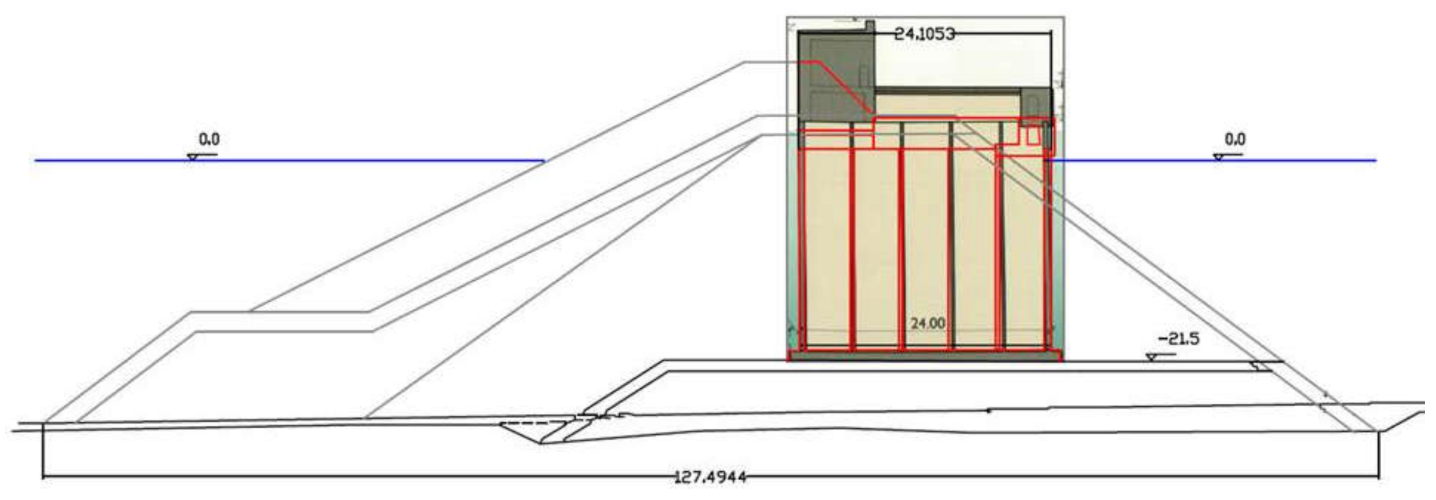
Figure 13 allows us to compare the breakwater initially planned for the port of Tarragona with rip-rap and the amount of materials necessary for correct termination. It is compared with an equivalent breakwater with concrete caissons, which performs the same shelter function as the rip-rap breakwater and was the one actually built. This leads us to caissons 66 m in length, 22.00 m in height, and a 24.00 m beam. They will allow the wave action existing in the area to be resisted (Hs = 7.50 m, Tp = 14 s, Hdesign = 13.17 m, Return period 300 years).
Savings in materials in this case would be approximately 80%. In one of the cases, rid-rap, blocks of mass concrete, and all-in-one material shall be used when, in the case of the caisson, reinforced concrete and much less quarry material shall be used. Quite frankly, this is more respectful with the environment than a rip-rap breakwater. We are trying to find a unique number (as could be, initially, the CO2 emissions value) to have a qualitative comparison of both systems. First, rough calculation shows us double CO2 emissions for rip-rap breakwaters than for caissons breakwaters.
The less occupied sea bed is an additional advantage as far as environmental impact is concerned.
Moreover, the inside of the caisson can be used to confine dangerous waste (by sealing) or it may be used as a dump with both impacts being positive.
4.2. A Search for a Reduction in Steel: Fiber Containing Concrete
The first evolution in the system was to reduce both the use of cement and the use of steel in the structure. This can be achieved, in a certain way, by adding fiber glass to the concrete which, despite its not replacing the main reinforcements [
1], does at least reduce the total amount of steel in allowing secondary reinforcements to be eliminated and to improve the characteristics of the cement and its compression and tensile strength. This also allows a reduction in the use of cement in the mix [
6].
4.3. Fiber Glass Bar Reinforced Concrete
Fiber glass bars began to be used in some structures as replacement for steel bars even though this option has not been applied to caissons so far. They have been used in maritime works such as the sea wall of the port of Escombreras for reinforcing the wave exposed surface [
66]. These bars are available on the market and, although they cost initially more than steel, there are more and more cases where this solution is cost effective [
67,
68], considering maintenance costs among others. This wall, on the sea side has fiber bars (22 kg/m
3, around 8 €/kg) and steel bars in the other side (19 kg/m
3, around 1 €/kg).
Using this type of reinforcement would allow steel to be eliminated (with the consequent advantages for corrosion and with less regulatory restrictions). In addition, savings in fresh water would be allowed since there would be no problem in using seawater. There would be no chloride-steel reactions.
4.4. Towards More Sustainable Materials: Composite Materials
This is the most “extreme” option for avoiding the use of quarried materials, cement, and steel since practically only composite materials would be used. This is the ultimate turn of the screw towards evolution in sustainability, which commences with the change in type to reinforced concrete caissons and finishes by using caissons with none of the classic materials currently used in the construction world (aggregate, cement, and steel).
Composite materials may significantly contribute to reducing both the Eco-footprint and CO
2 emissions since they usually make less impact than traditional materials [
69,
70].
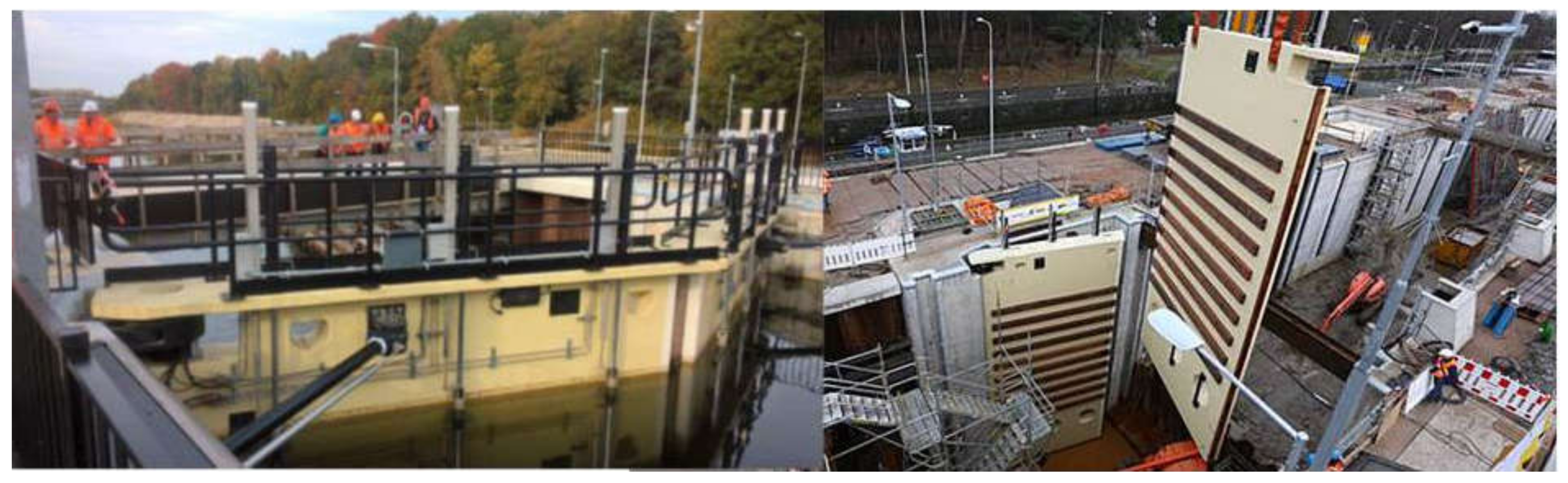
There are many examples for the use of composite materials in newly constructed structures (bridges, building, locks, and in all kinds of water structures such as Dolphins [
69] or lock gates [
70] (
Figure 14) and in sheet pile works). In concrete facades, the possibility of constructing complex forms is a strong point. The release of this structure would not reside so much in the permanent contact with water but with the need to consider a structure of enormous dimensions, which will be used first as a vessel and then must withstand in time the impact of the waves in situations of saturation in sea water.
The caissons will be in much more extreme conditions than what has been used so far since it is in a situation of saturation in an aggressive environment and permanently requested by the strong waves. They will also have two different functions since it initially floated and then the final and static function was resisting the impact of loads of wave actions in a rough climate.
Carbon fiber is also used but fiber glass has more ecological characteristics (less energy consumption for its production) [
73].
Through adaptation to more efficient and less contaminating construction systems and the use of new materials calling for less use of natural resources, civil engineering is used to develop beneficial infrastructures for improving the quality of life of human beings with less resource consumption and more sustainable development criteria.
Maritime works can be constructed in a more respectful way for the environment by replacing traditional materials.
5. Fiber Structures and the Circular Economy
As it has been before, fiberglass caissons are a very interesting option in terms of sustainability, which means it is possible to analyze the particularities of this material, how to fit them within the framework of the circular economy, and lastly see what solutions contribute this material to the equation between costs and sustainable development. One of them to take into account and to investigate is the construction of recycled fiberglass caissons for maritime structures.
5.1. Fiber Glass
Fiber glass represents 95% of the composite materials currently being produced. The most common type being used is E-glass. Silica is the main component in glass [
74], but specifically in E-glass, which is mainly composed of SiO
2 (55%) and CaO (22%) and in a minor degree of Al
2O
3 (14%), B
2O
3 (7%), and MgO (1%).
Silica is a semi-metal element and, after oxygen, the second most abundant element in the earth’s crust [
75,
76]. It is found in the form of silicate SiO
32− and in sand in the form of silica SiO
2. There shall be, therefore, no problems as to a lack of this material, but there are other reasons for reducing its use as a raw material.
Glass making is a high energy consuming industry [
77] and, despite the fact that the use of fiber glass is more sustainable than concrete, this process can also be optimized by energy saving in its production or, as it will be seen further on, by recycling fiber glass, which is the process that consumes much less energy [
78].
Both sand and quartz proceed from quarry workings and a reduction in their use will contribute to a reduction in the environmental impact of the process.
Fiber comes in many formats whether in groups of strands or fabrics [
79]. In the case of fabrics, they may be unidirectional, woven, non-woven, or multi-directional [
80].
5.2. Sustainability and Circular Economy in the European Union
Sustainability is in the DNA of the European Union. Article 11 of the Treaty on the Functioning of the European Union (TFEU) states that “Environmental protection must be integrated into the definition and implementation of the Union’s policies and activities with a view of promoting sustainable development.” In addition, Title XX (articles 191 to 193) establishes the objectives, principles, conditions, and procedures of environmental policy.
The European Union (EU) has endorsed both the SDGs and the Paris agreements. In its Communication Next steps for a sustainable European future, the European Commission considers that the SDGs are fully consistent with Europe’s vision and commits to “mainstream the Sustainable Development Goals into EU policies and initiatives with sustainable development as an essential guiding principle for all its policies” [
81].
The European Commission engages to lead the efforts to achieve the 21st Conference of the Parties (COP21) objectives, which encourages the transition towards a low-carbon, resource-efficient economy, which is seen as an opportunity for growth and jobs [
82].
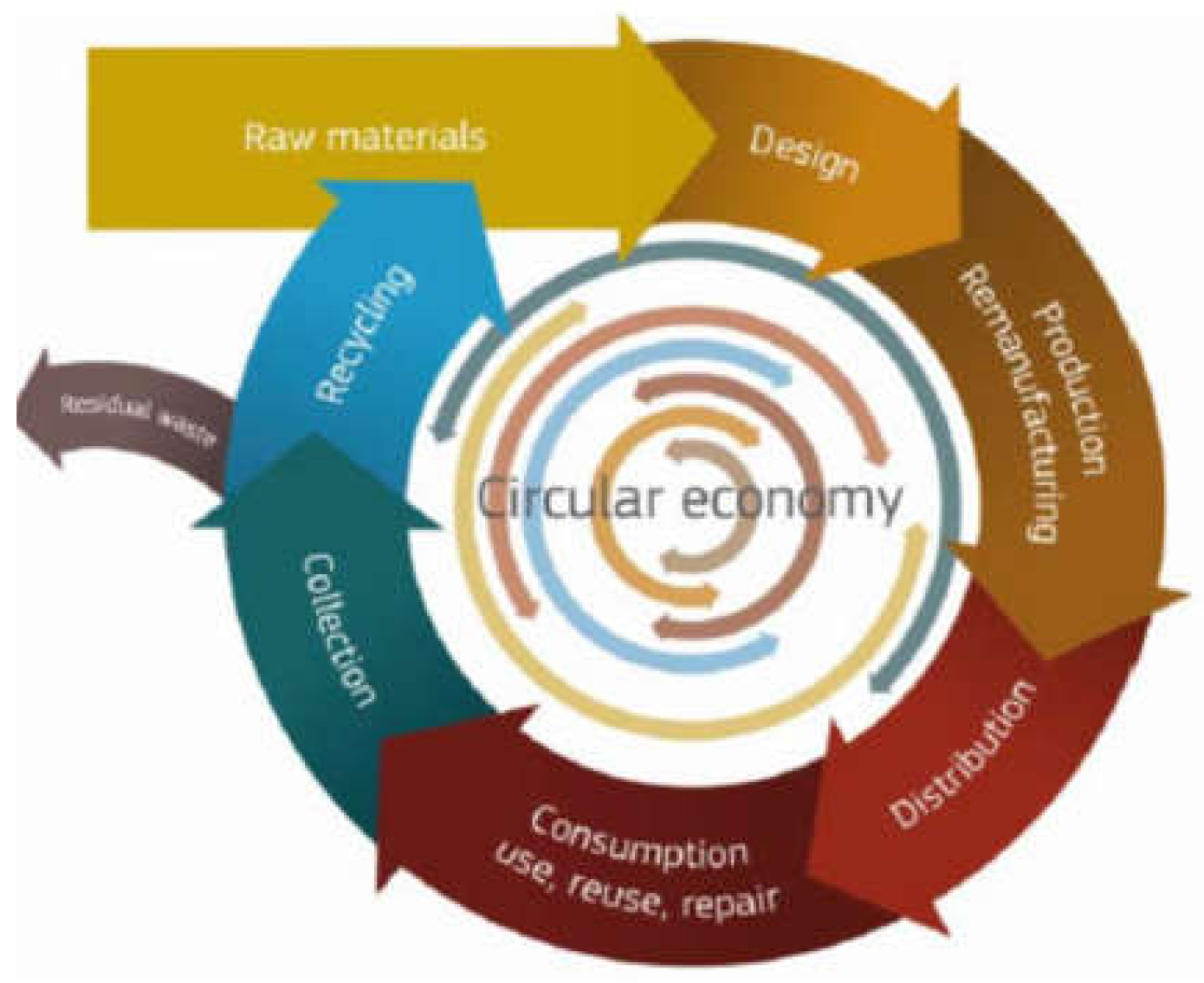
The EU’s commitment with the SDGs and the COP21 Paris Agreement is consistent with other strategies launched at almost the same time. This is particularly the case of the “Circular Economy Package” adopted in December 2015. The circular economy is perceived as a model to reach some of the above-mentioned goals. The objective of the “Circular Economy Package” is to push businesses and consumers to make the transition to a more circular economy where resources are used in a more sustainable way, which produces benefits for both the environment and the economy. It is deemed that such a transition will develop a sustainable, low-carbon, and resource efficient society by boosting EU’s competitiveness through the creation of new business opportunities and innovative and efficient ways of producing and consuming [
83].
The Circular Economy strategy consists of an EU Action Plan formulated in the European Commission Communication Closing the loop—An Action Plan for the Circular Economy [
84]. It announces a program of actions that cover the full life cycle of products: from production and consumption to waste management and the market for secondary raw materials. It also includes an annex, which sets out the timeline of actions to be completed, and benefits from financial support by the European Structural and Investment Funds (ESIF) and the EU program for Research and Innovation, Horizon 2020—The latter providing a support of €650 million between 2016 and 2017 and nearly one billion between 2018 and 2020. The rationale of the circular economy concept is presented in
Figure 15 [
37].
We can easily deduce that we shall be increasingly nearing the aim of a Circular Economy. The lesser the exit flow from the circuit, i.e., the lowest amount of residual waste is produced.
A new concept should, therefore, be introduced when designing. Thinking not only of the stage of the product’s use but also of optimum re-use of materials is important [
85].
The European Union prioritizes energy and resource efficiency and waste is considered as a potential resource that has to be treated according to the “waste hierarchy” defined in the Waste Framework Directive (Directive 2008/98/EC). This Directive explains when waste ceases to be waste and becomes a secondary raw material (so called end-of-waste criteria) and establishes that, in waste management, prevention must prevail, followed by preparation of waste for re-use, recycling, recovery, and, only finally, disposal. It is also worth noting the EU’s Raw Materials Initiative, which aims at ensuring a sustainable supply of raw materials for the European economy, resource efficiency, and the supply of “secondary raw materials” through recycling and, last but not least, ensuring access to raw materials from global markets.
This directive is clearly pointing towards the reuse of materials and makes great sense in the glass and carbon fiber market where, currently, the immense majority of products (vehicles, aero-generator blades) ends their useful lives in dumps or, in the best of cases, are burned to produce energy in cement making.
There is evidence supporting this approach. Today, over 80 billion tons of materials are extracted per year of which a mere 7% is reused or recycled by energy and industry [
86,
87]. It is estimated that promoting circular economy strategies can mitigate about half the emissions gap between national climate mitigation commitments for 2030 and the 1.5 degrees trajectory [
88] and that, by 2050, policies to improve resource efficiency could reduce global resource extraction by up to 28% relative to existing trends. Combined with ambitious global action on climate change, resource efficiency policies would cut global GHG emissions by around 63% and boost the value of economic activity by 1.5% [
89]. In Europe, the total energy savings potential from increased recycling represents around 5% of total primary energy consumption in the EU28, which may lead to GHG emission reductions representing 2.5% of the EU28 total. Other valuable resources such as water and land would also be saved [
90]. The reconfigure study [
91], focused on energy-intensive industries like steel, plastics, aluminum, and cement and two large use segments for these materials (passenger cars and buildings), estimates that circular economy measures could reduce EU industrial emissions by 56% (300 Mt) annually by 2050, which is more than half of what is necessary to achieve net zero emissions. Globally, the reductions could be 3.6 billion tons per year in the same period.
The Circular Economy Strategy includes a “Circular Economy Monitoring Framework” with indicators to follow-up the implementation of the strategy in Europe. One critical issue to estimate the environmental and climate footprint of products (and infrastructures) is to take into account their entire lifetime. For this, the EU promotes the use of Life Cycle Assessments, which would cover, for instance, the environmental and climate impact of extraction of raw materials, transport, transformation, and use until its transformation for re-use or recycling or disposal. LCAs imply applying a series of techniques and data collections, but allow comprehensive vision of environmental impacts and economic costs including externalities, in the long term, during the full life of products.
To put all this in order, for example, in the case of plastics, there are a number of measures planned to encourage, on the one hand, innovation and, on the other hand, to penalize depositing plastic waste in dumps and its incineration. This will allow recycling plastics in general and fiber glass in particular to be more competitive (EU strategy for plastics [
92]).
5.3. Fiber Glass Recycling
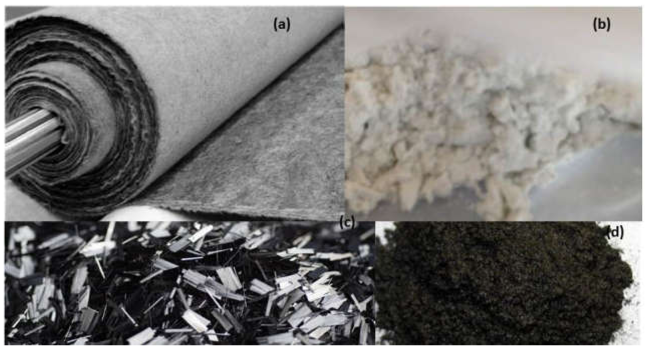
Still very incipient, in some cases, recycling is already being successfully performed by industrial processes. In the case of carbon fiber, which commenced its recycling process in 2015, the ELG Company, for example, produces non-woven mats and GRP dust from carbon fiber by grinding and then a chemical pyrolysis process, which can be seen in
Figure 16.
Now implanted in an industrial manner, this process may reduce the cost of the material by between 40% and 70% depending on whether it is combined with virgin carbon fiber in a greater or lesser proportion. Certain reductions occur in the material’s properties with 10% in tensile strength.
High temperatures are required for performing recycling processes, which consume a large amount of energy [
95] but less than that is required for making the virgin product.
In the case of fiber glass recycling, the most complex problem was found in thermo-setting resins (epoxy, polyester, and vinyl ester) since these materials cannot be remolded again due to cross linkages [
96]. The same does not occur in the case of thermoplastic resins (polyethylene, polyurethane, polypropylene, and polyvinyl chloride) whose processing is easily reversible.
The most usual solution for fiber glass waste both in Europe and in the United States is to take it to a dump [
96,
97], but the recent growth in recycling and encouragement from the circular economy is leading us to different types of recycling as well as to incineration whether producing energy or not [
96].
The growing importance of composite materials (20% of the 120 kg de plastic currently used in vehicles) [
96] also brings with them a growing problem of the generation of this type of waste, which reached 216,000 tons a year in 2005 [
96]. The annual demand for polymeric fibers (FRP) in the United States in 2017 came to 2 million metric tons and fiber glass represented 95% of the total [
98]. Bearing in mind that fiber glass is not a biodegradable material, the vast majority of the waste involved is taken to dumps.
Several options are open for reusing fiber glass composites. In one of these cases the “co-processing in cement kilns”, which is a different process to incineration [
70], advantage is taken of the high calorific value of thermosetting resins up to some 30,000 kJ/kg using this material. The organic fraction [
69] is used as an efficient fuel in cement kiln roasting and provides additional energy when most needed. The incombustible inorganic part is used as aggregate for the cement, which improves its properties. This enables us to make savings in fuel in the order of 10% [
96]. This procedure is economically viable and allows the ecological footprint in cement making to be improved [
69].
On co-processing composite material, silica is obtained, which may be added to the cement or re-used in new composites [
99].
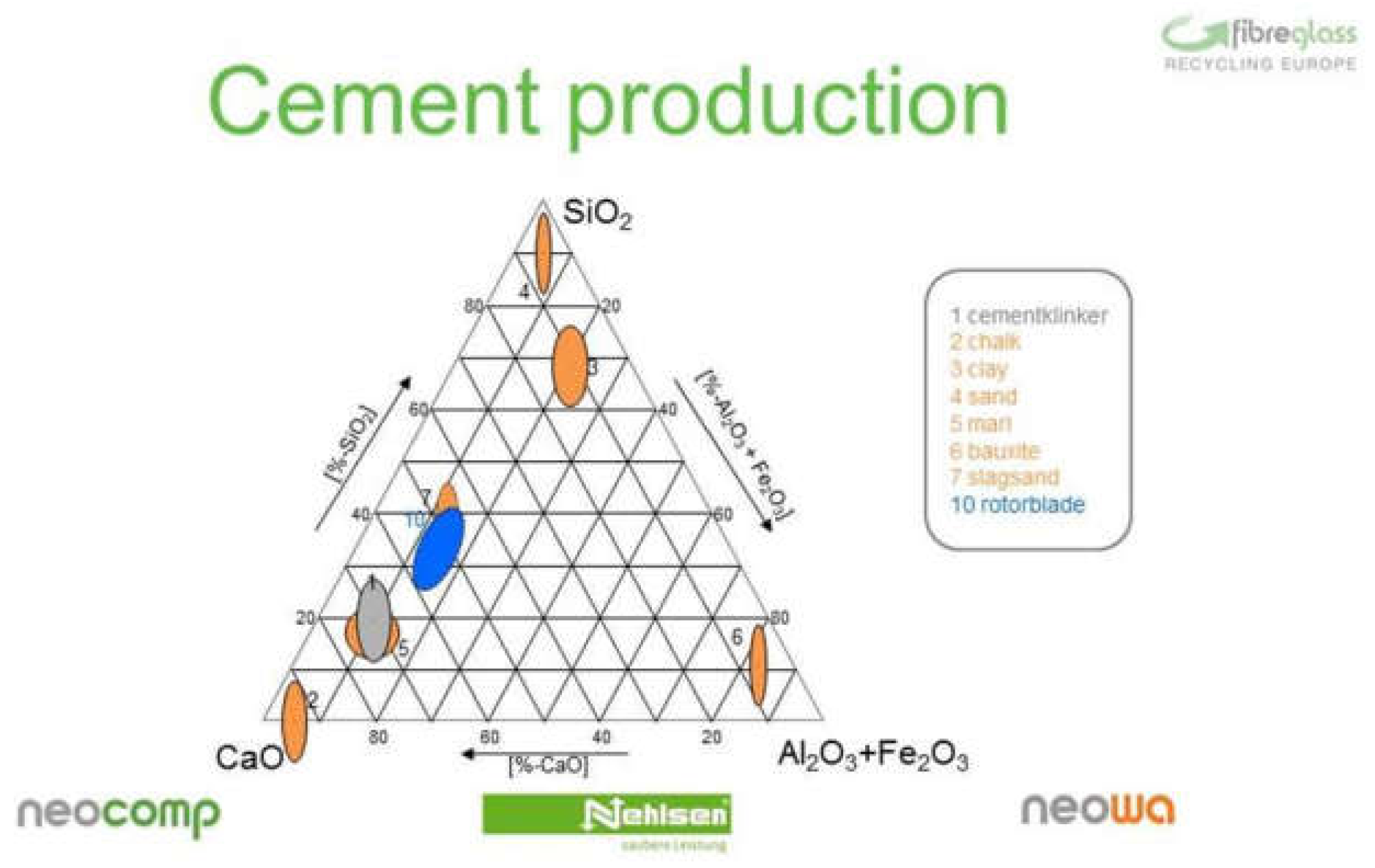
Using glass fiber thermoset regrind is ideal for making cement since it provides an optimal mixture of calcium oxide, silica, and aluminum oxide, which is very similar to that of clinker, as can be seen in
Figure 17 where the characteristics of wind blades give a very similar product in composition. Furthermore, CO
2 emissions are also very much lower in clinker production and may well reduce by up to 16% [
69]. Let us not forget that cement represents 7% of total CO
2 emissions from energy and industry, which means that any action on this material has a great global effect [
91].
This specific sector is important since the useful life of the first wind farms is coming to an end and the number of blades to be replaced will grow exponentially [
100]. A system which suitability recycles them will prevent much waste in dumps and will provide a large amount of reusable fiber.
As an example, the Neocomp company has been recognized by the Green Tec Awards in 2017 for its process for thermal recycling of GRPs and their reuse in cement production [
101].
By grinding, this same company produces a fine granulate which, when mixed with paper, is an ideal aggregate in cement production since it provides silica, which is a highly beneficial product for the cement’s properties [
100].
This procedure is one of the ways to prevent fiber glass waste ending up in dumps but also should be promoted technologies that reintroduce fiber glass as a secondary raw material. The most widespread technology to this effect is the production of smaller sized fibers by crushing and even grinding the fiber glass elements that have consumed their useful life. Other systems also exist even though, in some cases, only as a patent. These systems use chemical processes allowing fibers to be separated out from resins [
102]. This system would be the one to allow to reason more completely in terms of the circular economy since fiber glass would be reintroduced into the production system to make new parts.
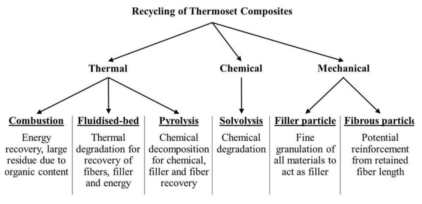
There are mechanical and chemical methods as well as thermal methods for treating waste for recycling [
97], which can be seen in
Figure 18. Recycling of thermoset resins is harder than thermoplastic ones [
95], but they are the most commonly used in composite materials [
99]. This is why many methods are used and investigated.
Mechanical methods are used commercially in the case of thermosetting polymers. They reduce the size of the recycled material and obtain fibrous elements or reduce them to dust. Energy consumed for this crushing is between 0.17 Mj/kg of material in the case of thermoplastic composites with polypropylene/flax as a natural fiber and 0.31 MJ/kg in the case of the fiber reinforced polymer sandwich [
97]. Let us recall that 75% of Fiber Glass (GFRP) is made up of thermosetting polymer composites [
98].
In the case of thermal methods both in the pyrolysis process and the fluidized bed thermal process, it is intended to separate reinforcing fibers from their polymer matrix. In the case of combustion, a thermal process and equal sized fibers are not obtained. On achieving a very high rise in temperature, these methods may lead to a major loss in product properties if very high temperatures have been reached (90% reduction in temperatures higher than 650 °C) [
96].
Pyrolysis is expounded as the only scalable thermal process on a commercial level [
99].
In the case of solvolysis, which is a chemical recycling process, the composite material is dissolved with different solvents and the resulting products are used as new raw material [
99].
As a statistic, which can be learned from Gutierrez and Bono [
97], 98% of fiber glass and only 2% of carbon fiber is found in composite material recycling.
5.4. Recycled Fiber Glass
The most exceptional procedures for composite material recycling, which could be of use in the evolution of port caissons, are described below.
The first is the use of cement proceeding from GRP combustion or the addition of ground GRP as an aggregate to the cement for caisson concrete. With better properties, this cement allows savings in proportioning [
69].
Another option is to replace the concrete’s aggregate for parts of crushed composite materials but the resulting concrete will lose mechanical strength and it shall not, therefore, be taken into consideration [
96].
Several companies offer recycling systems based on pyrolysis or on solvolysis and allow the carbon fiber or glass fiber to be recovered in the form of small elements or even to recover the fiber matrix in its initial state by extracting resins using a patented process (with some loss of properties depending on the procedure used: loss of mechanical properties between 18% and 30% between recycled and virgin fiber glass [
99]). Should the Fluidized Bed combustion process be used, working at high temperatures (450–500 °C), property losses in the fiber are high and its strength is reduced to half in comparison with virgin fibers [
99].
The possibility of recovering fiber matrices to be reused leads us to a much less expensive material as raw material. It has a mechanical characteristic sufficient to build a certain type of structure, which could be port caissons. The possibility might arise for using recycled carbon fiber due to its more affordable price.
In some cases, properties are lost in recycled material but the new products can be sized by taking these restrictions into account. As known, the main advantages are price and much less production energy consumption.
A field of application in civil engineering opens up for the use of composite materials at much more affordable prices. Whole series of elements with not too demanding structural requirements may be candidates for the use of these recycled materials and so actively contribute to the circular economy.
Contrary to the specific case of fiber caissons, weight is not a problem since the caisson’s floatability reserve is very high. In this case, what would hold sway would be the cost, which is one of the main handicaps of fiber glass. The simplicity of caissons as a structure and only the relative importance of their weight could make the solution of fiber against concrete economically viable.
6. Discussion
The evolution undergone in the last century in caisson construction in maritime works together with the use of new materials and new sustainability policies take us to a search for solutions in accordance with current needs with ever more environmentally-friendly materials.
The possibilities of composite materials may be considered as a useful system under certain conditions but too expensive for concrete. This is why it has not been taken into consideration with due attention except in point cases.
However, the possibility and need to reuse materials within the framework of an environmentally-friendly circular economy offers us a raw material with much more affordable and competitive prices with traditional solutions.
The possibilities of composite materials in caisson building are highly varied particularly bearing in mind the functional requirements of new caissons and desirable, increasingly larger sizes. This all clashes with the manifest limitations of concrete whether due to complex forms, size, or logistics, etc.
Concrete caissons have allowed for a great evolution in maritime technology and industrialization in the port construction process. However, they may advance as to size and complexity due to new materials.
Since the possibility of obtaining recycled composite materials allows for the price difference to be less determining, it is highly important to continue with the search for solutions using these materials.
The use of finite element techniques for the design of maritime structures with composite materials is already bearing fruit and offers results very close to laboratory tests. The greater complexity of the future structures will happen in any case by estimations in numerical models in order to not have to make expensive laboratory 3D models.
There is already a detailed methodology for calculating the life cycle of a product and there are already some examples of companies that calculate the EPD for complete works.
Therefore, a way to compare the most sustainable option according to our conditions (investment, environment, maintenance, durability, ...) would be to calculate by finite elements the different solutions as stated in the document (reinforced concrete with steel bars, reinforced with fiber bars and fiber only), to have a clear sizing, and to be able to establish the costs of each of the solutions and, thus, establish its EPD card.
It is a long process that, if systematized, will allow us to choose the best solution in terms of the circular economy, which establishes an environmental product declaration of the caisson.
7. Conclusions
Caisson technology developed spectacularly in the 20th century. This development was major because of the use of floating docks but also through the evolution of dry construction techniques.
Both systems were more industrial than civil in nature.
The problem involving the water/cement ratio and corrosion in building caissons may be a determining factor when using floating elements in caisson construction.
On its part, dry construction calls for large esplanades, machinery, and specialized equipment as well as specific launching and control systems.
The development of vertical breakwaters is leading to an evolution in structure forms. Caissons are becoming increasingly more complex and longer. This complexity makes both floating docks and dry dock construction increasingly more difficult to use and this technology has to evolve or give way to new techniques or materials complying with the new requirements. Experimental models carried out demand for new construction methods and materials since the present ones are not adapted to those new shapes.
These new processes seem to be leading to dry construction but with composite materials. Using the latter, large sized elements and complex forms may be industrially produced with lesser construction, launching, and control systems.
Caissons are already being dry constructed. They reach the maximum displacement capacity of naval shipyards and, therefore, the use of lighter materials will allow us to build much larger elements with the existing auxiliary resources.
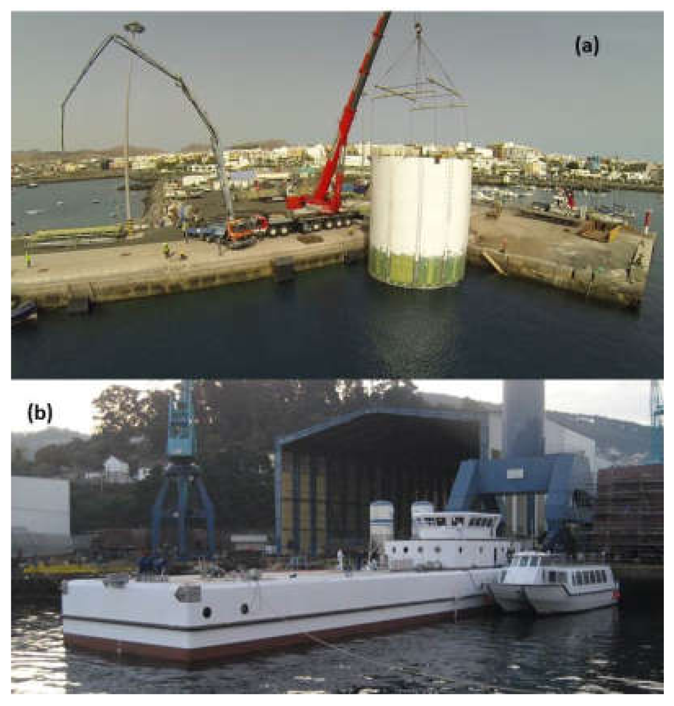
Currently, new materials are being used only in environments where maritime climate actions are limited such as the Port of Rosario’s dolphins [
103] and fiber glass pontoons (
Figure 19). Both experiences can, therefore, be used to evolve towards large dimensioned caissons for breakwaters. Composite caissons are perfectly adapted to this situation of permanent saturation in an aggressive environment and solicitation to waves.
The costs of these new materials may be positioned at this time very much above those of conventional materials derived from a lack of industries carrying out this process and the high price of materials, but there is a lot of leeway for improvement. Savings in maintenance of structure should be considered too to evaluate cost-effectivity.
Introducing the circular economy concept allows us to seriously consider the use of composite materials in their recycled version. This would give a major saving in supplies as well as greater sustainability in building maritime works.
The search for adapting to new forms by using suitable construction materials and systems opens up an enormous field of investigation, which will supplement the concern for obtaining optimum forms in designing vertical breakwaters.
The cheaper way to go forward is to calculate the different options by fast (or simplified) methods and establish the life cycle of each of the solutions. A broader vision will, thus, be obtained and will allow decision-making on the most appropriate solution in each project.
The next case is, therefore, to dimension the caissons for the different solutions (included with recycled fiber) and calculate their EPD in order to select the most suitable, which lays the foundations of the procedure to be followed in the future for the choice of the ideal solution in the framework of a multi-criteria analysis.

 ,
, 


