In this section, to calculate the ATR spectrum of the Kretschmann configuration to excite HSPPs, we firstly derive the reflectivity of a three-layer dielectric system (
/
/
) by means of the BPM, whose schematic diagram is shown in
Figure 1. Then, we make the expressions of the reflectivity extend to the Kretschmann configuration with a metal interlayer. Finally, the validity of the expressions for the reflectivity is proved by the FDTD method and the reported experimental result.
2.1. Reflectivity Expressions of the Kretschmann Configuration
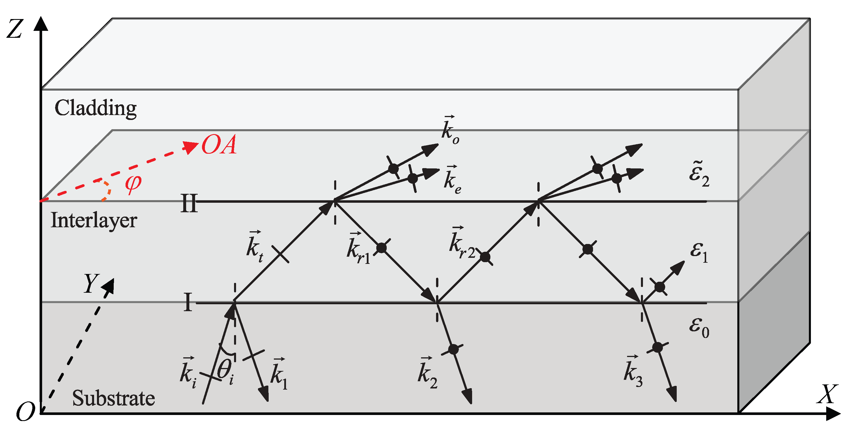
In
Figure 1, a uniaxial dielectric cladding and a rare isotropic dielectric film are deposited on a dense isotropic dielectric substrate, where their dielectric constants are
,
and
from up to down respectively. Their dielectric constants satisfy the relations:
, where
are the principal dielectric constants of the uniaxial dielectric cladding. The interface I exists between the substrate and the interlayer. The optical axis of the uniaxial dielectric cladding is parallel to the interface II between the uniaxial cladding and the interlayer dielectric. A monochromatic TM plane wave is incident from the substrate to the interlayer, where the complex amplitude of its electric field is expressed as
where
is a complex-constant amplitude and
is the incident wave vector propagating at an incident angle
.
Figure 1.
Reflection of a transverse magnetic (TM) plane wave in a three-layer dielectric system, where both the substrate and the interlayer are isotropic media, and the cladding is a uniaxial dielectric with optical axial (OA) parallel to the interface.
Figure 1.
Reflection of a transverse magnetic (TM) plane wave in a three-layer dielectric system, where both the substrate and the interlayer are isotropic media, and the cladding is a uniaxial dielectric with optical axial (OA) parallel to the interface.
At interface I, the incident wave is divided into the reflected wave
and the refracted wave
. The wave
incident at interface II is partly reflected back at interface I, and the other part gives rise to two refracted waves
in the cladding. The wave
is divided into the refractive wave
and reflected wave
. The process of the division of the wave remaining in the interlayer continues as described in
Figure 1. It is to be noted that, when a TM wave is incident from the interlayer to the cladding, the reflected fields at interface II are a superposition of TE and TM waves. In other words, in this system with anisotropic cladding, the polarization of reflected waves is different from that of incident waves. Similarly, for TE input light, the same results are expected. For analysis convenience, we divide the superposition fields emitted from the interlayer to the substrate into TM and TE waves.
In our three-layer dielectric system, we mark the amplitude reflection coefficient
r and the amplitude transmission coefficient
t as
and
, where subscripts i, j = 0,1,2, and the sequence order of i and j means that the former is an incident medium and the latter is a refractive medium. The subscripts p and q denote a TM or TE wave, respectively. The sequence order of p and q denotes that the former is the polarization state of the incident wave and the latter is the polarization state of the wave reflected or refracted. That is, p, q = TM, TE. It is well known that
r and
t are given by the Fresnel formulas [
13] at the interface between two kinds of isotropic media. While, for
r and
t at the interface between an isotropic medium and a uniaxial dielectric, one can refer to [
9].
For brevity in the derivation, we define the following coefficients
,
,
,
,
,
,
and
:
When a TM plane wave is incident from the substrate to the interplayer, the complex amplitudes of the TM waves reflected from the interlayer include the following terms:
,
,
,
,
, etc. Similarly, in the substrate, the complex amplitudes of the TE waves reflected from the interlayer are expressed as
,
,
,
, etc. The
δ is the phase difference between adjacent beams in the substrate
where
d is the thickness of the interlayer.
If all TM and TE reflected waves in the substrate are superimposed separately, the total complex amplitudes of TM and TE waves of the three-layer dielectric system can be expressed as
Therefore, the total reflectance in the three-layer dielectric system is given by the sum of TE and TM reflectance
where
φ is the azimuth angle between the direction of the optical axis in the interface and the plane of incident; and
and
represent the reflectance of TM and TE waves in the substrate for a TM incident wave, respectively. It is evident, when the thickness of the interlayer
d is of known, that the total reflectivity
is a function of the incident angle
and the azimuth angle of the optical axis
φ in this system.
As is well known, the theory of the multiple-beam interference with a plane-parallel plate keeps its validity for a three-layer system composed of a dense isotropic dielectric substrate, a plane-parallel metal film and a uniaxial dielectric cladding with the optical axis parallel to the interface, if it only involves linear relations between field vectors of a time-harmonic wave [
13]. Therefore, if the real dielectric constant
in expressions (2)–(12) is replaced by a complex dielectric constant of a metal film, we can get the reflectivity of the Kretschmann configuration with an anisotropic cladding in the case of a TM plane wave incident from the substrate.
2.2. Verification of the Reflectivity Expressions
In order to evaluate the accuracy of the analytical method, several key comparisons between two ATR curves based on the BPM and the FDTD method, and based on the BPM and an experiment reported in the paper [
2] are implemented. We firstly calculate the ATR spectrum of the Kretschmann configuration by the reflectivity expression (13). Then the numerical simulation by means of the FDTD method is performed by the commercial software FDTD Solution (FDTDS). A TM plane wave incident from the substrate is kept in the simulation and the parameters of materials chosen in the simulations are separated into two sets. The parameters of one set with the strongly anisotropic cladding are as follows [
7] :
- (1)
The substrate dielectric constant is = 12;
- (2)
The dielectric constant of Au at the wavelength 1.0 μm is i, and the thickness of the Au film is d = 50 nm;
- (3)
The principal dielectric constants of the uniaxial dielectric are and ;
- (4)
Considering the conditions for excitation of HSPPs, choose the azimuth angle of the optical axis , , , respectively, and change the incident angle from 0 to 90.
The parameters of the other set with the weakly anisotropic cladding are follows [
2]:
- (1)
The dielectric constant of ZF7 as the substrate is at = 650 nm.
- (2)
The dielectric constants of silver at the wavelength from 620 to 730 nm are from the experimental data [
14], and the thickness of the Ag film is
d = 57 nm.
- (3)
The azobenzene polymer is used as the cladding. When a pump laser irradiates the cladding, its principal dielectric constants are and . While, the dielectric constant without the pump light is , standing for an isotropic medium.
- (4)
As the same as the conditions of the paper [
2], we also set the condition that no pump,
,
, and
, respectively, and keep the incident angle
at a fixed value of
.
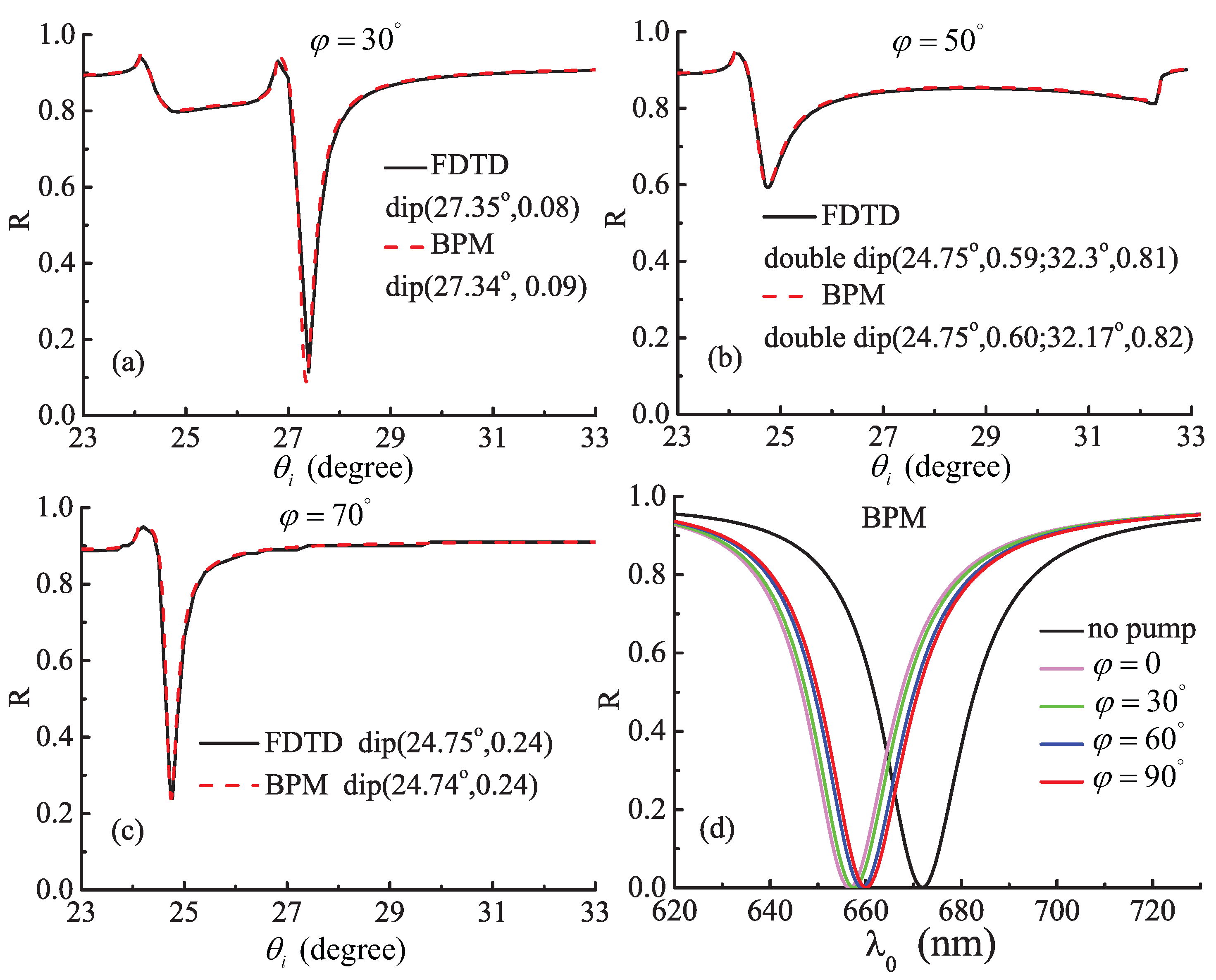
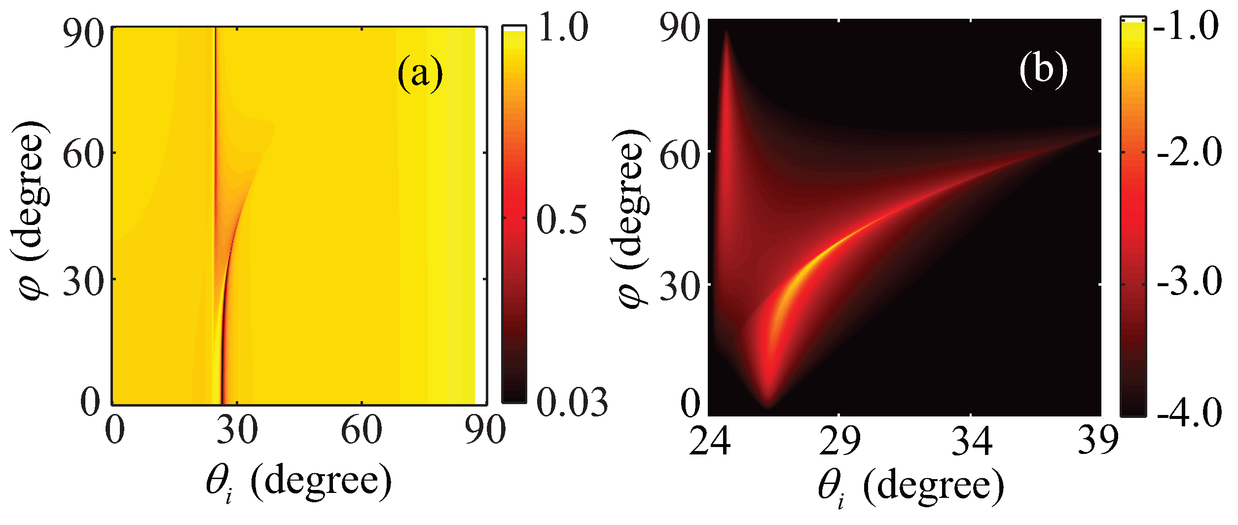
The total reflectivity
as a function of the incident angles
and the azimuth angle of the optical axis
φ is displayed in
Figure 2, when a TM light is incident this system. In the first three graphs
Figure 2a–c corresponding to the parameters of the first set materials, the black solid and the red dash lines are the results of the FDTDS and the expression (13) derived by the BPM, respectively. According to the resonance angle, the value of
in the dip of the reflectivity, and the shape of curves, it is evident that the results of the BPM excellently agree with the ones of the FDTD. The parameters of the last graph
Figure 2d are in accordance with those of the second set materials, and the color curves are calculated by the expression (13). Under different conditions with no pump,
,
,
, and
, the resonance wavelengths are 672, 656, 658, 659, 660 nm, respectively. Compared with the
Figure 3a in the paper [
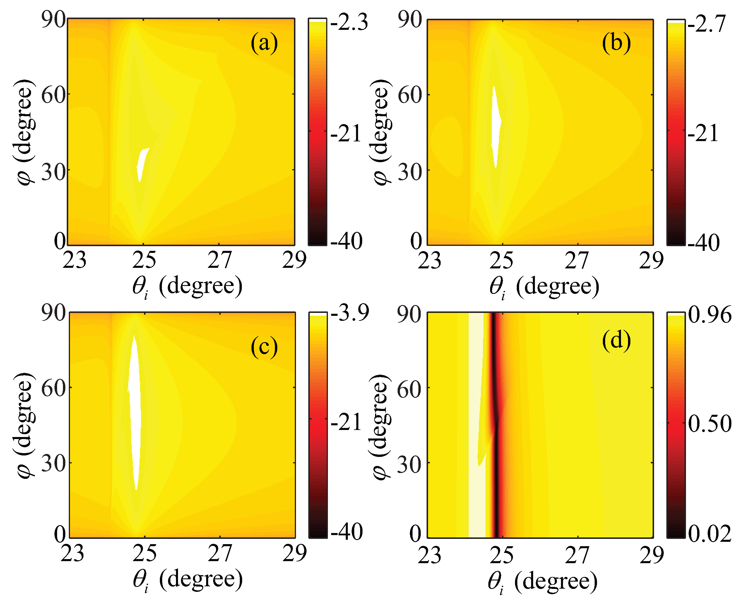
2], the change tendency of the resonance wavelengths is quite consistent, although the different values are approximately equal to 10 nm. The results indicate that the expressions (11)–(13) can accurately compute the ATR curves of this system for any parameters. Furthermore, using the analytical expressions it takes only several seconds to describe one ATR curve on a PC equipped with 8 Inter(R) Core i7-2600 CPUs @ 3.4 GHz and 16 GB RAM.
Figure 2.
Comparison between attenuated total reflection (ATR) curves from the beam propagation method (BPM) and the standard which are the finite-difference time-domain (FDTD) method and the results of the experiment in the paper [
2], respectively. The first three graphs compare with the result of FDTD method; while the last one may be compared with the result of the experiment in the paper [
2]. The total reflectivity
Rtotal of this system is a function of the azimuth angle of the optical axis
φ, incident angles
and the resonance wavelength
.

