
The Effect of Different Non-Metallic Inclusions on the Machinability of Steels


Abstract
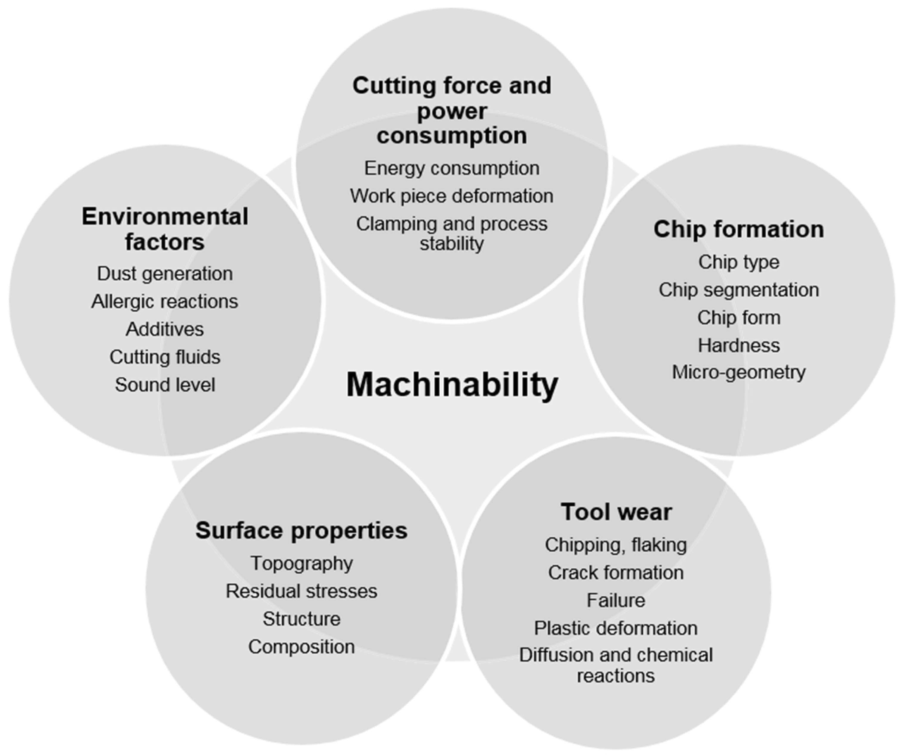
:1. Introduction

2. Metal Fracture during Machining
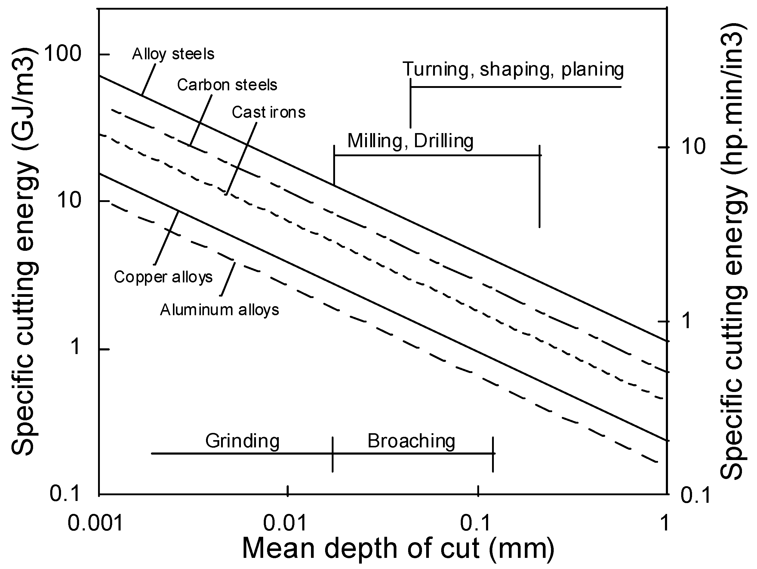
2.1. Different Techniques of Mechanical Machining


- Act as stress raisers in the shear plane, which cause a crack formation. This, in turn, leads to embrittled chips that are easily broken. In addition, the length of the contact zone between the chip and the cutting tool is reduced. Thus, is advantageous for the tool wear resistance.
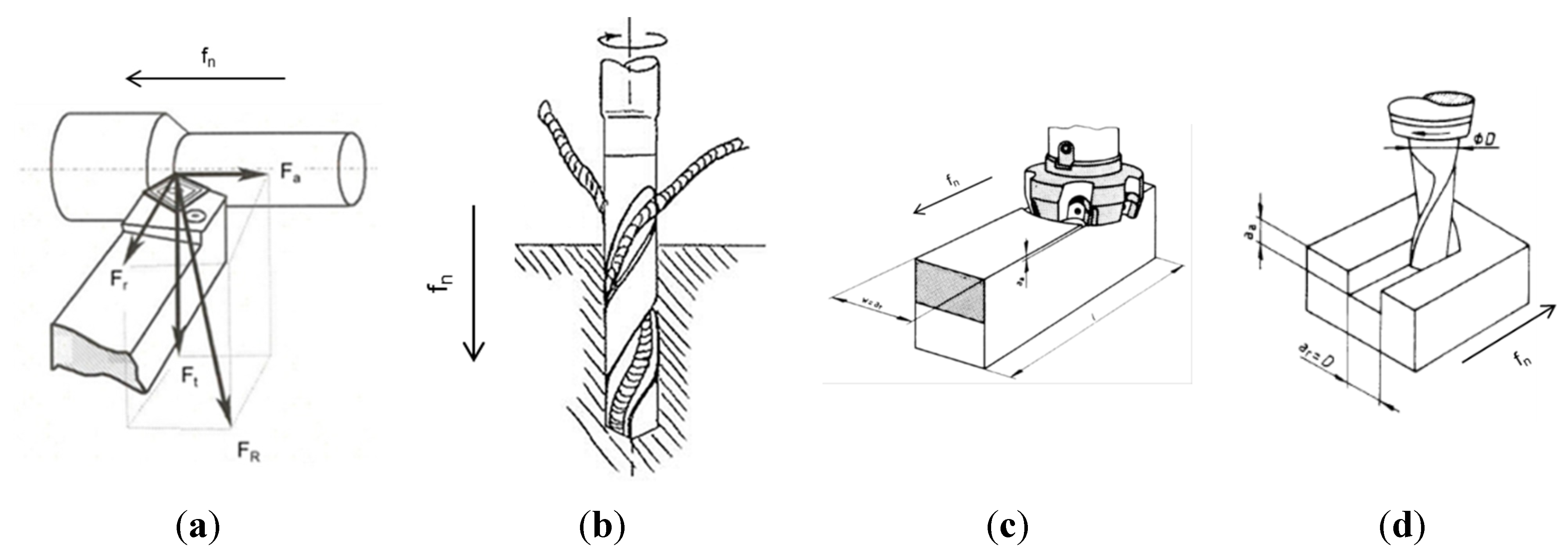
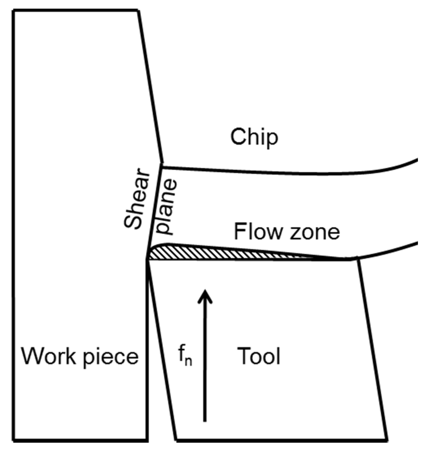
- Are active in the metal flow zone (see Figure 7, where fn is the feed direction) and contributes to shearing of the metal. However, an appropriate balance of inclusions is necessary to avoid an increased tool wear rate.
- Form a diffusion barrier, isolating the rake face from diffusion induced chemical tool wear at high temperatures.
- Act as lubricant which protects the flank face of a cutting tool from an abrasive wear.

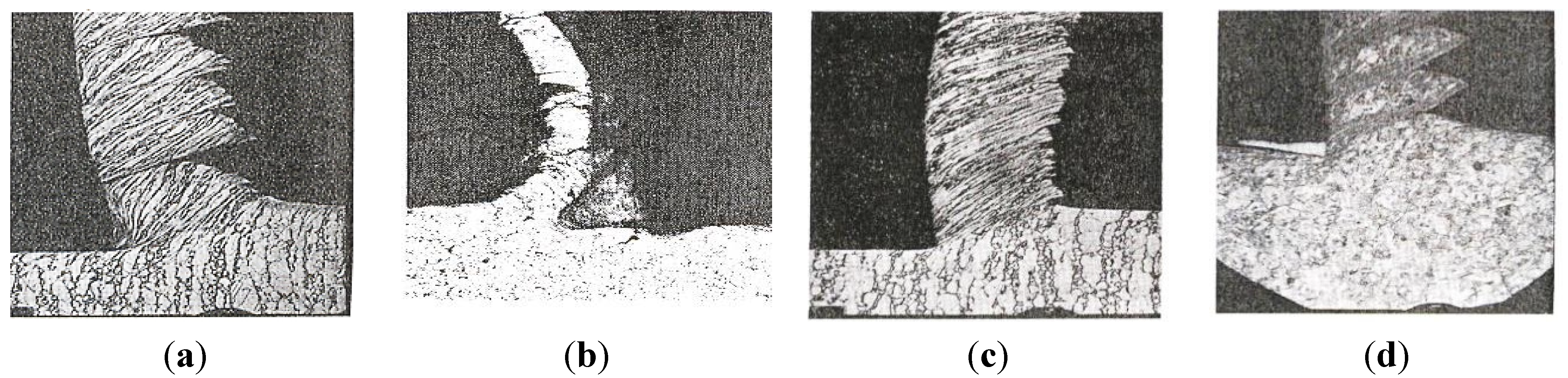
2.2. Behavior of Non-Metallic Inclusions in the Cutting Zone


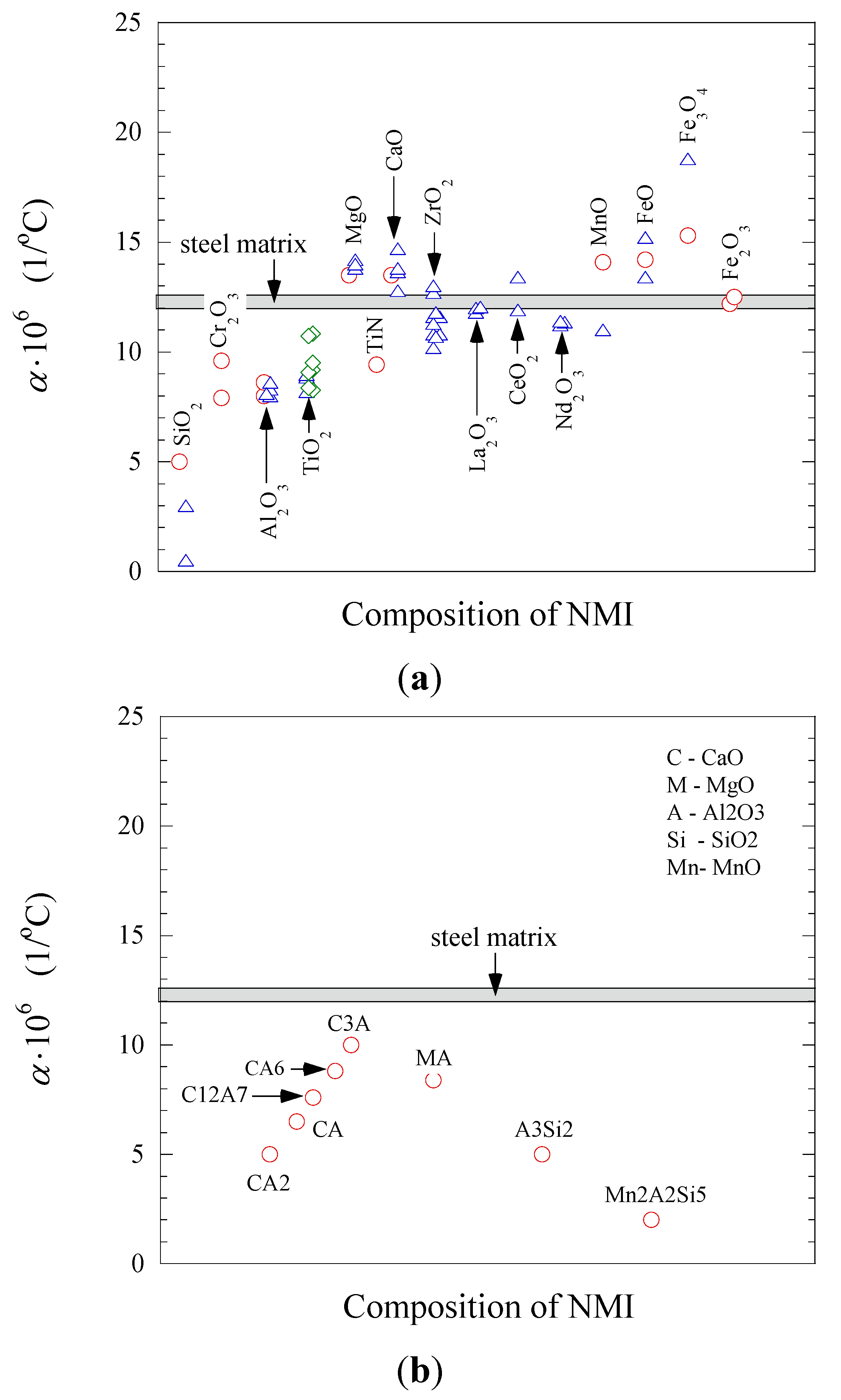
| Coefficient of Thermal Expansion | Group 1: αNMI < αsteel | Group 2: αNMI ~ αsteel | Group 3: αNMI > αsteel |
|---|---|---|---|
| Heating |  |  |  |
| Stress in NMI | No effect | Stress in steel matrix around NMI | |
| Cooling |  |  |  |
| Stress in steel matrix around NMI | No effect | Formation of cavity and pores around NMI |

| Operation | Si-Deoxidation | Al-Deoxidation | Ca-Treatment (Modification of Oxides) | Addition of S | Ca-Treatment (Modification of Sulfides) | REM-Addition (Modification of Sulfides) | Addition of Zr, Ti, V, Nb or B |
|---|---|---|---|---|---|---|---|
| Non-metallic inclusions (NMI) | SiO2, SiO2-MnO-... | Al2O3, Al2O3-MgO | CaO, CaO-Al2O3, CaO-Al2O3-... CaO-SiO2-… | MnS, (Mn,Fe)S | Ca(O,S), CaS, (Ca,Mn)S | REM-Ox, REM(O,S)x, REM-Sx | ZrN, Zr(N,C), TiN, Ti(N,C), BN, B(N,C), BC, etc. |
| Formation of NMI in steel | Partially in liquid steel. Partially during solidification of melt due to high content of soluble O (~60–80 ppm) | In liquid steel | In liquid steel | During solidification of melt (large size sulfides—mostly in final solidified zones) | In liquid steel | In liquid steel | Mostly during solidification of melt. Partially after solidification of melt |
| Size of NMI in cast metal | 1–8 µm | 0.1–8 µm | 1–25 µm | 0.5–30 µm | 1–5 µm | 1–3 µm | 0.01–7 µm |
| Condition/ Morphology * | Liquid or solid/SP and RE | Solid/Mostly RE and IR | Liquid or solid/Mostly SP | Solid/Mostly RE and IR | Solid/Mostly SP | Solid/SP and RE/IR | Solid/Mostly RE and IR |
| Distribution in steel | Mostly homogeneous | Mostly homogeneous | Mostly homogeneous | Mostly in final solidified zones, S inhomogeneity | Mostly homogeneous | Mostly homogeneous | Mostly on grain boundaries |
| Cluster formation | No | Very easy. Size of clusters 10–1000 µm | No | Dendrite or coral shape sulfides (Type II and IV), 10–100 µm | No | REM-oxides. Size of clusters 10–300 µm | TiN-“clusters”. Size of clusters 5–30 µm |
| Hardness of NMI (kg/mm2) | Middle/Low (~1600) | High (~3000) | Middle/Low (850–1200) | Low | Middle/Low | High | High |
| Deformability of NMI | Low at T < 900 °C High at T > 1000 °C | No at T < 1300 °C Low at T ≥ 1500 °C | No at T < 1200 °C High at T ≥ 1300 °C | Very high at T < 1000 °C | No at T < 1200 °C Low at T ≥ 1300 °C | Very low | Very low |
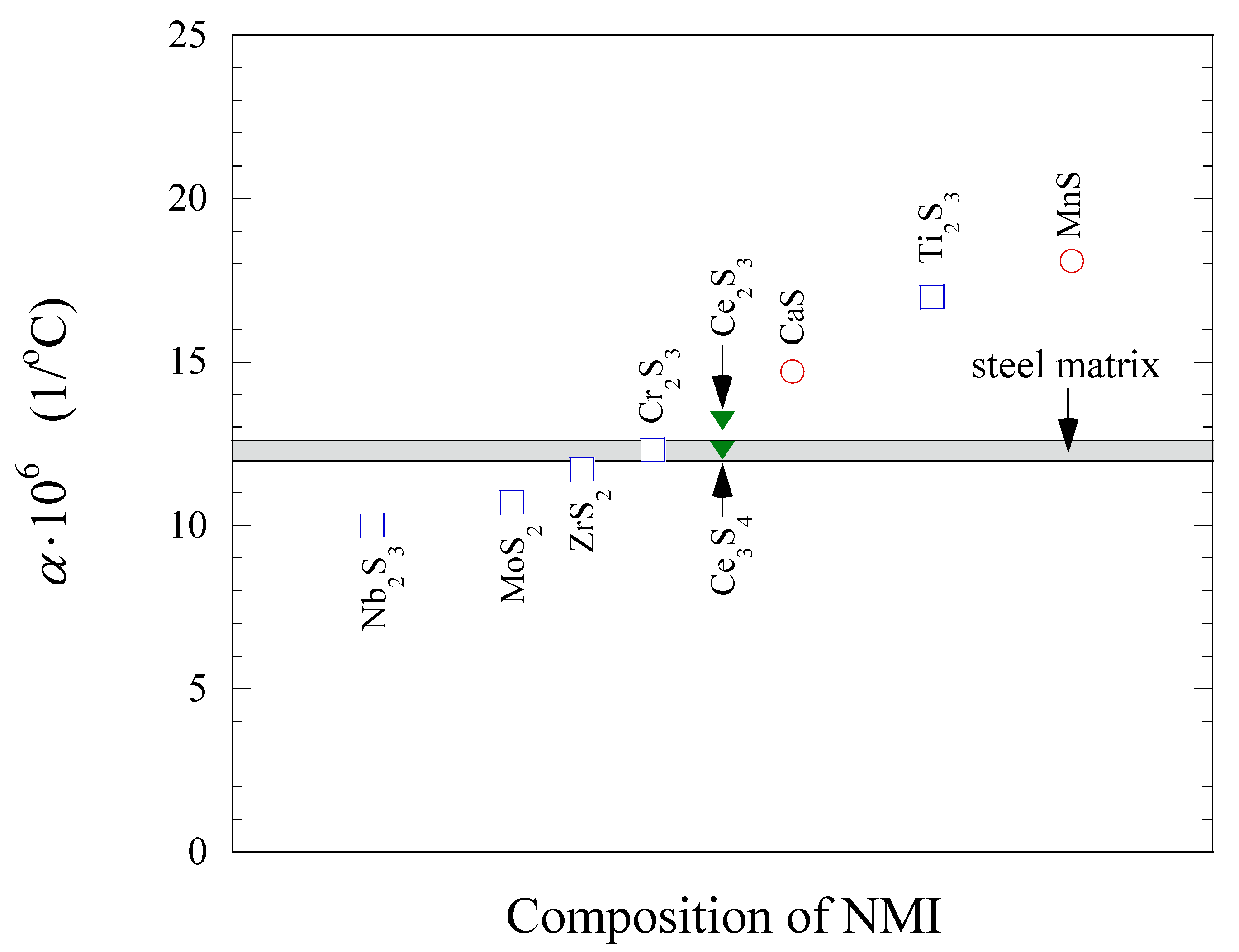
| Thermal expansion, α (×10−6 1/°C) | Very low (0.5–5.0) | Low (8.0–8.6) | Low/middle (for CaO-Al2O3 5.0–10.0) | MnS—high (18.1) | CaS—high (~14.7) | REM-Ox—middle (11.2–13.4) REM-Sx—middle (12.3–13.2) | TiN—low (~9.4) |
| Non-Metallic Inclusions (NMI) | SiO2, SiO2-MnO-... | Al2O3, Al2O3-MgO | CaO, CaO-Al2O3, CaO-Al2O3-..., CaO-SiO2-… | MnS, (Mn,Fe)S | Ca(O,S), CaS, (Ca,Mn)S | REM-Ox, REM(O,S)x, REM-Sx | ZrN, Zr(N,C), TiN, Ti(N,C), VN, V(N,C), BN, B(N,C), BC |
|---|---|---|---|---|---|---|---|
| Effect of NMI on the mechanical properties of steel. | No or some anisotropy of mechanical properties of steel due to low elongation of silicate inclusions during deformation. | No anisotropy of mechanical properties of steel. |
|
|
|
|
|
| Effect of NMI on the machinability of steel. |
|
|
|
|
|
|
|
3. Non-Metallic Inclusions in Different Steels and Their Link to Machinability Tests
| Ref. | Year | Steel Grade a | Inclusion Characteristics | Machinability Parameter b | Main Result |
|---|---|---|---|---|---|
| [25] | 1995 | “Clean”, carbon | (Mn,Ca)S, elongated, (CaO-Al2O3), globular | TL | Ca-treatment improves machinability |
| [26] | 1995 | “Clean”, carbon, M‑steel | (Mn,Ca)S, elongated, (CaOAl2O3), globular | TL, TW | Ca-treatment improves machinability |
| [27] | 1981 | Ca-treated, carbon, M‑steel | CaO-Al2O3, globular, CaO-Al2O3-SiO2, anorthite, globular | TL, TW | Ca-treatment improves machinability |
| [5] | 2007 | Ca-treated, medium carbon steel, 0.35%–0.40% C, 0.02%–0.04% S | Al2O3-MgO, regular, CaO-Al2O3, 12CaO-7Al2O3, globular | TW | Ca-treatment improves machinability |
| [28] | 1993 | SS 2541, Q & T | MnS, elongated, (Mn,Ca)S, globular, (CaO-Al2O3)-(Mn,Ca)S and CaO‑Al2O3-SiO2, globular | TL, TW | Decreased flank wear progression due to Ca‑treatment |
| [29] | 2013 | 42CrMo, Q&T, 0.42% C, 0.0067% S | BN, globular, 5–20 µm | TW, CC | BN improved the machinability (drilling) |
| [30] | 1999 | AISI 4140, Q&T, 0.0017%–0.0030% Ca, 0.4% C | MnS, (Ca,Mn)S, globular | TL, CF | Reduced torque and adhesion due to Ca-treatment |
| [1] | 1993 | SS2541, ~0.35% C, 0.035% S 825B BB, 1% C, 0.011% S | MnS, (Ca,Mn)S, (CaO-Al2O3)-MnS, AlCaMnS | TW, CF | The protective (Mn,Ca)S layer reduced the crater wear |
| [31] | 1984 | SS 2506, CH, S, Ca ~0.2% C, 0.04%–0.09% S, 0.0003%–0.0054% Ca | MnS, elongated, (Mn,Ca)S~elongated, (CaO-Al2O3)-(Mn,Ca)S and (CaO‑Al2O3-SiO2)-(Mn,Ca)S, globular | TL, TW | S and Ca-treatment improves machinability |
| [32] | 1986 | SS 2506, CH, Ca additions 0.04%–0.09% S | MnS, elongated, (Ca,Mn)S, (CaO-Al2O3)-(Mn,Ca)S, globular | TL, TW | Ca-treatment improves machinability |
| [33] | 2001 | 40 CrMnMo8 Carbon 0.4% C, 0.008%–0.067% S | MnS, elongated, 20–100 µm, oxides, globular, 10 µm | TL, TW, CC | S addition increased the machinability by 40% |
| [34] | 2001 | AISI 4340 ~0.4% C, 0.012%–0.034% S, 0–50 ppm O, 0–25 ppm Ca | (CaO-Al2O3)-(Mn,Ca)S, globular, 2–10 µm | TW, CF, CC | Ca-treatment indicates ridge formation after hard part turning |
| [35] | 1984 | Structural steel | S, Se, Pb, Ca | TL | Additions of S, Se, Pb, Ca improved the machinability |
| [36] | 1975 | Free mach, 0.3% S | MnS, elongated | TL, TW, CF | S additions improved the machinability |
| [37] | 1975 | Free mach., 0.1% S | MnS, elongated, Al2O3, globular | TL, TW | S additions improve machinability |
| [38] | 2006 | Free mach., 0.6% C, 0.3% S | MnS, elongated, 5–40 µm MnFe(Al,Si)S | CF, CC, SR | Cold deformation may improve machinability |
| [39] | 2012 | Free mach., ~0.08% C, ~0.4% S | MnS, elongated, 10–20 µm (MnO-Al2O3)-MnS, globular, 15 µm (MnO-SiO2)-MnS, elongated, 20 µm | TW, CC, SR | Increased oxygen content improved the machinability |
| [40] | 1997 | Free mach., 0.4% C, 0.1% S | (Mn,Ca)S, MnS, elongated, <10 µm, (RE,Ca)2S3-(Mn,Ca)S, Re2S3-MnS, globular, <10 µm | TW | Ca and RE additions increased the machinability of free‑cutting steels |
| [41] | 1996 | Free mach., stainless steel, 0.04%–0.08% C, <0.1% S, <0.01% Ca | CaO-Al2O3-SiO2-MnS, MnS, Gehlenite, Anorthite | TL, TW, CF | Ca and S additions increased the machinability of stainless steel |
| [42] | 1990 | Stainless steel, 316 L 0.020%–0.027% C, 0.022%–0.025% S. 0.0002%–0.0045% Ca | MnS, (Mn,Ca)S, Gehlenite: Ca2Al[AlSiO7] + MnS Anorthite + MnS, elongated phases | TW, CF, CC | Anorthite inclusions are favorable for machining of 316L stainless steel |
| [3] | 2010 | Super-duplex stainless steel, 0.017%–0.021% C, 0.005%–0.034% S. REM additions | REM-O, Oxy-sulfides, (Mn,Cr)S, globular, 2–10 µm | TL, TW | S and REM additions increased the tool life but the corrosion resistance was decreased |
| [43] | 2011 | Austenitic stainess steel, 0.10%–0.11% C, 0.02%–0.11% S. Cu, Bi, Ti additions | MnS, Ti4C2S2, CuO, Bi, globular | TW, CF, CC | S, Bi, Cu and Ti additives improved the machinability |
4. Control and Correction of Non-Metallic Inclusions for Improving the Machinability of Steel
4.1. Increasing the S Content of Steel
| AISI Steel Grade | C | S | Mn |
|---|---|---|---|
| 1010 | 0.07–0.14 | 0.05 (max) | 0.25–0.60 |
| 1110 | 0.08–0.13 | 0.08–0.13 | 1.00–1.30 |
| 1037 | 0.31–0.38 | 0.05 (max) | 0.70–1.00 |
| 1137 | 0.32–0.39 | 0.08–0.13 | 1.35–1.65 |
| 1045 | 0.42–0.50 | 0.05 (max) | 0.60–0.90 |
| 1144 | 0.40–0.48 | 0.24–0.33 | 1.35–1.65 |
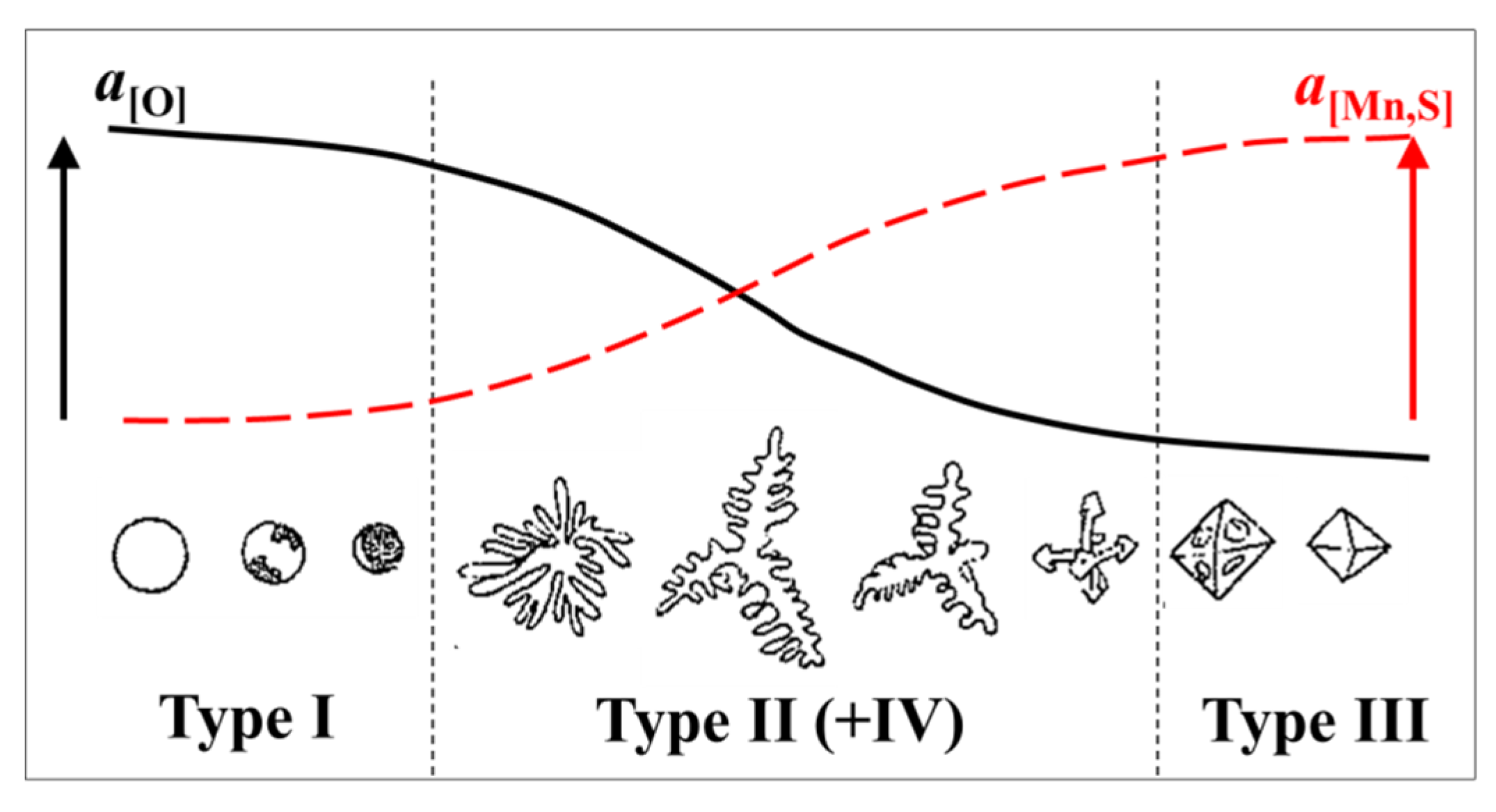
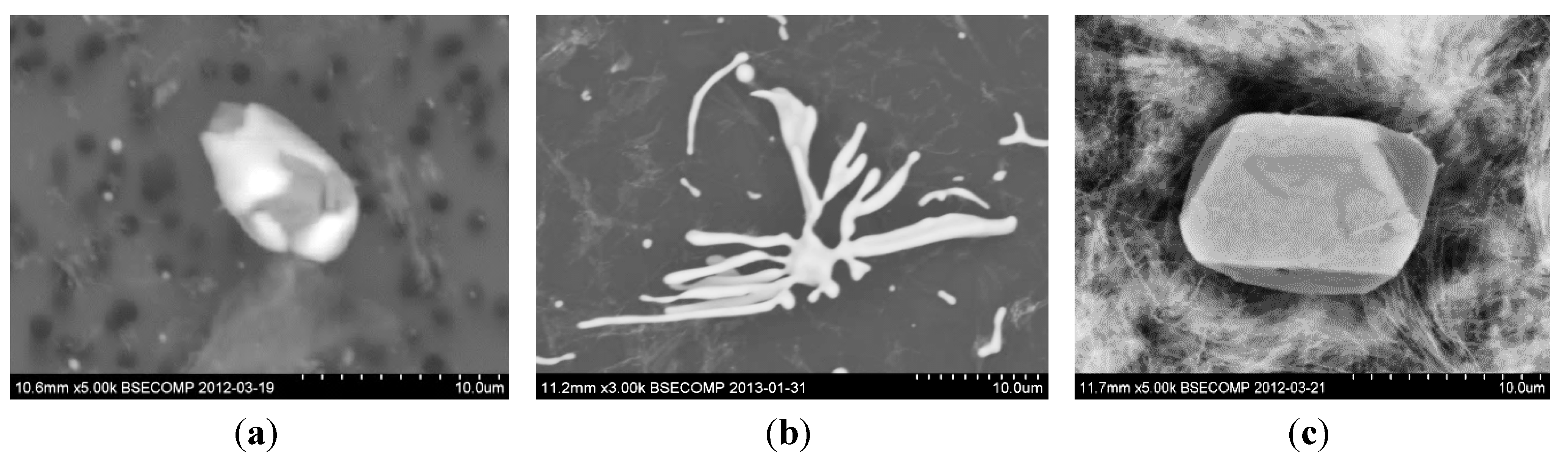
- Type I: globular, when the oxygen solubility is high and the sulfur solubility is relatively low. Such inclusions are formed by a monotectic reaction in rimmed and semi-killed steels (when aluminum in the steel is less than 0.001 wt.%).
- Type II: formed in the interdendritic spaces of austenite with a fan-like morphology. In addition, most commonly formed at grain boundaries of steel. These are formed in aluminum killed steels, without an excess amount of aluminum, as the aluminum content is about 0.007% in the steel.
- Type III: angular inclusions are formed as isolated particles in the interdendritic spaces, when excess aluminum is used for deoxidation resulting in about 0.038 wt.% aluminum in the steel.


4.2. Modification of Sulfide Inclusions by Addition of Ca, REM or Zr
- -
- change the composition and properties (physical and chemical) of sulfides;
- -
- change the sulfide morphology (globalization);
- -
- decrease the size of the modified sulfides;
- -
- obtain a homogeneous distribution of precipitated sulfides in the solidified steel.
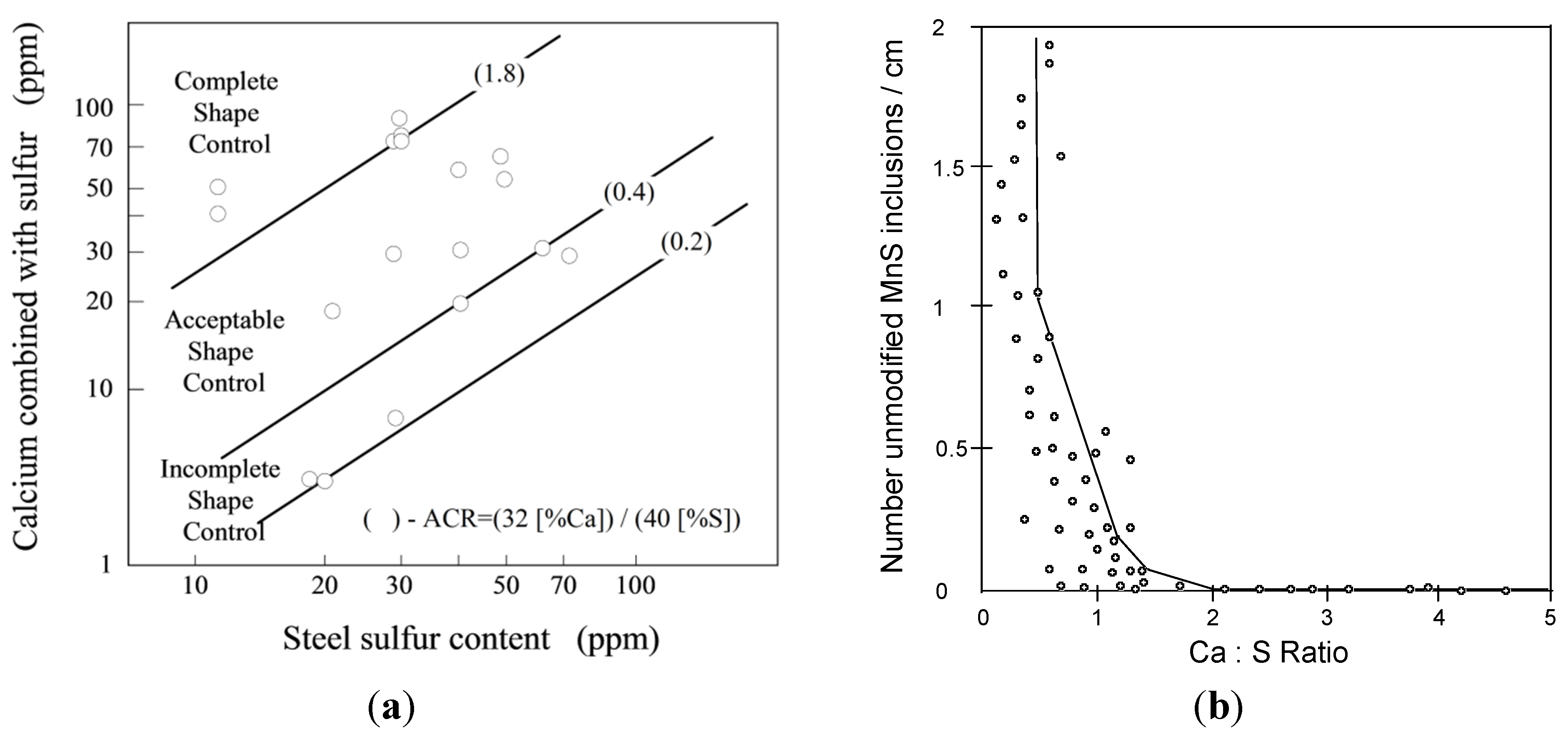
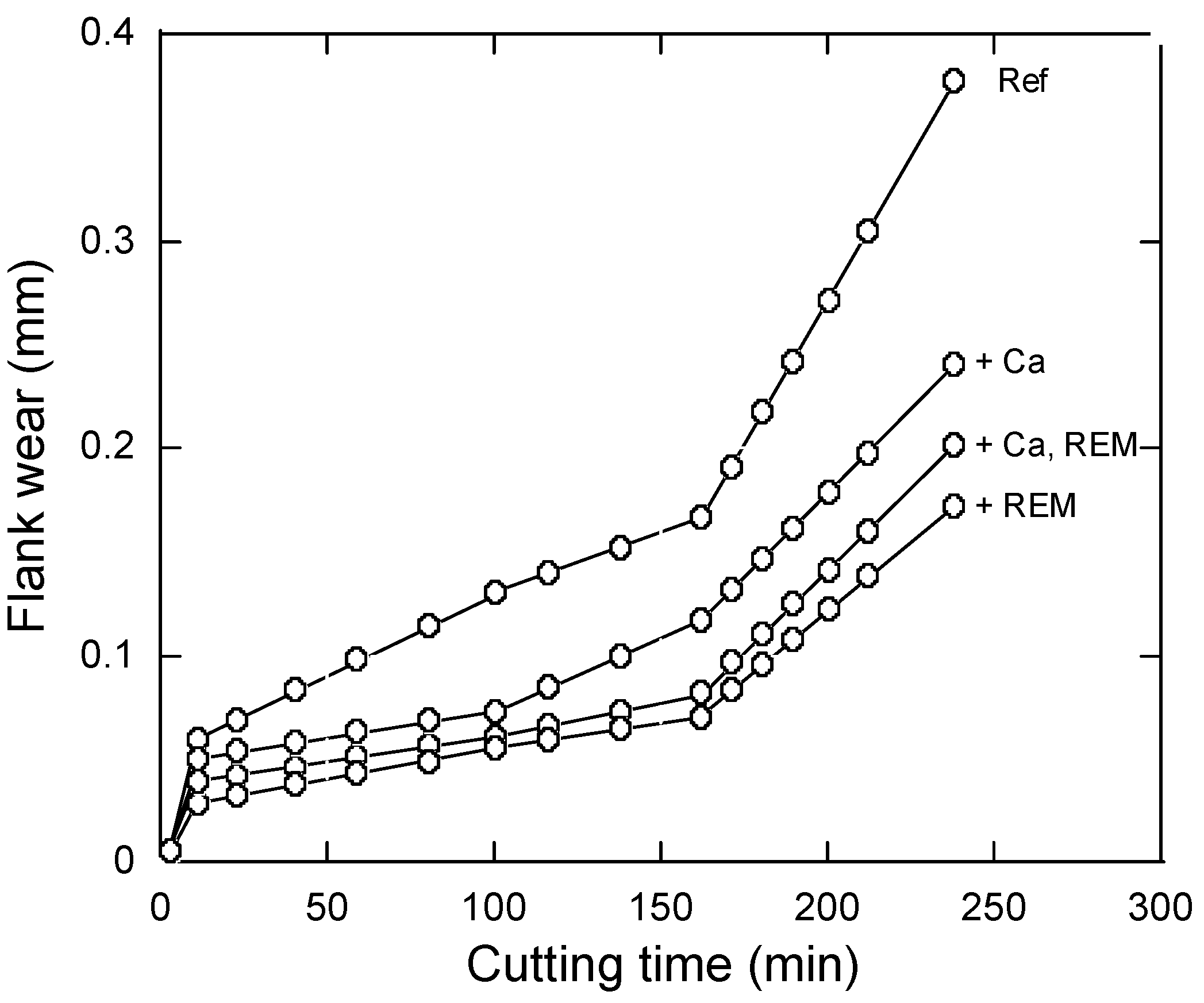
4.2.1. Calcium Treatment

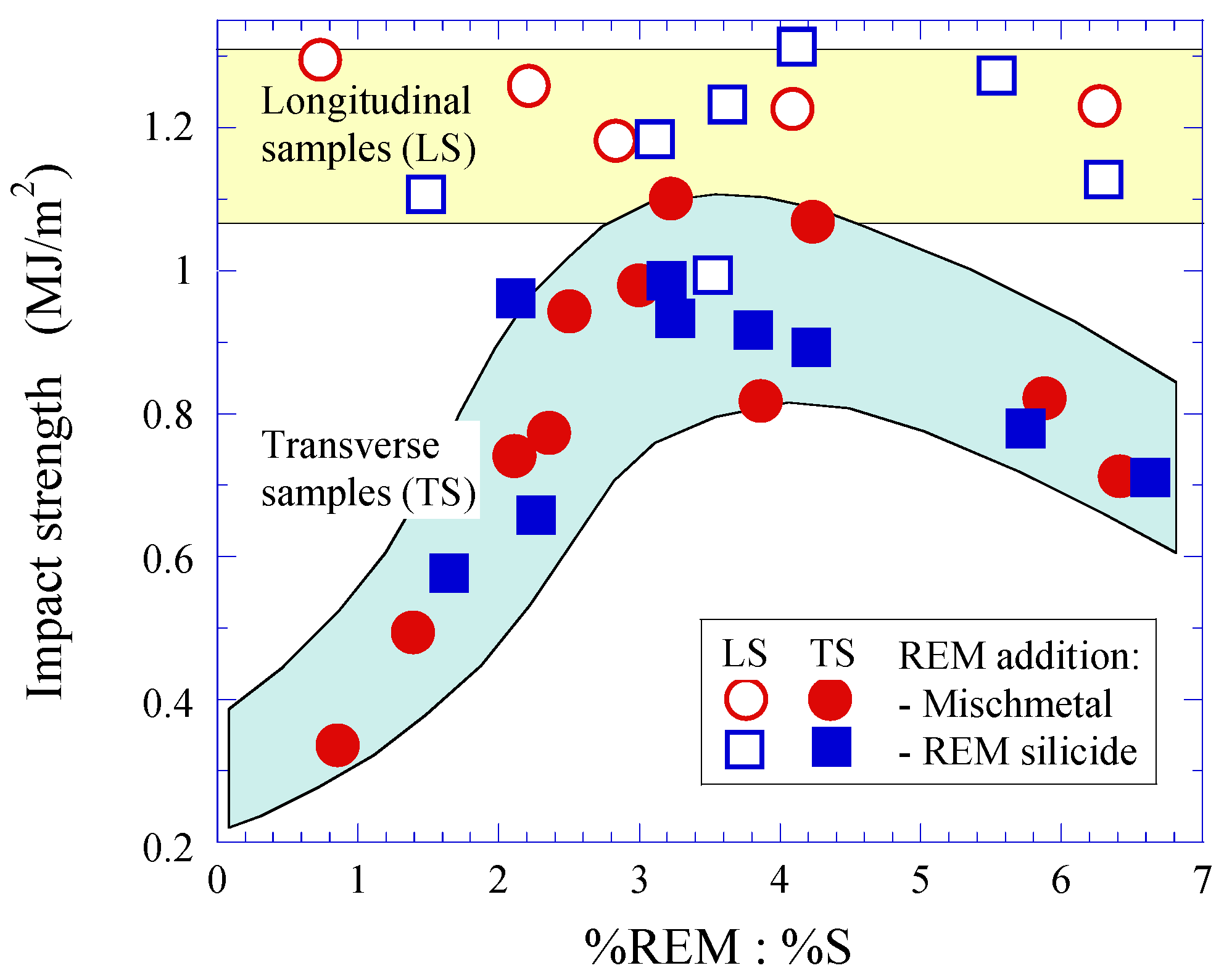
4.2.2. Rare-Earth-Metals (REM) Treatment


4.3. Modification of Oxide Inclusions by Addition of Ca
- (i)
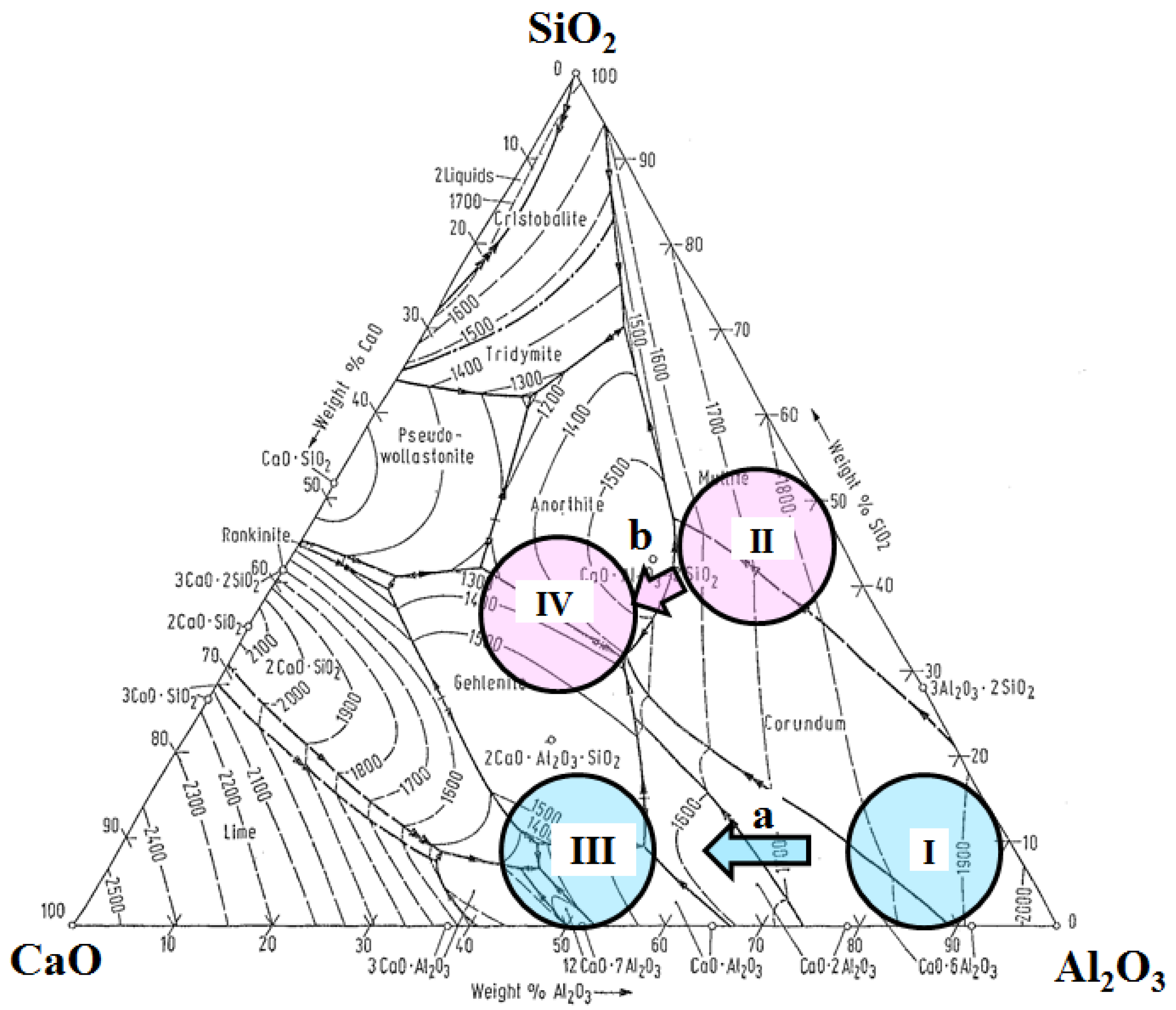
- to form the globular CaO-SiO2-... or CaO-Al2O3-... inclusions;
- (ii)
- to avoid the presence of SiO2 oxides, which have a high deformability at T > 1000 °C and which can increase the anisotropy of mechanical properties of steel after deformation;
- (iii)
- to avoid a formation of Al2O3 and Al2O3-MgO clusters in the liquid steel and clogging problems during casting;
- (iv)
- an application of relatively soft CaO-SiO2-… and CaO-Al2O3-… inclusions as natural lubricants for cutting tools during mechanical machining for improvements of the surface quality of machined steels and to increase the tool life (reducing the tool wear etc.).
| Steel | Ca-Addition | Main Type of Oxide | Main Type of Sulfide |
|---|---|---|---|
| 1 | No (Ref.) | Alumina, Al2O3 | MnS |
| 2 | Yes | Gehlenite, Ca2Al[AlSiO7] | MnS + (Mn,Ca)S |
| 3 | Yes | Anorthite, CaAl2Si2O8 | MnS |
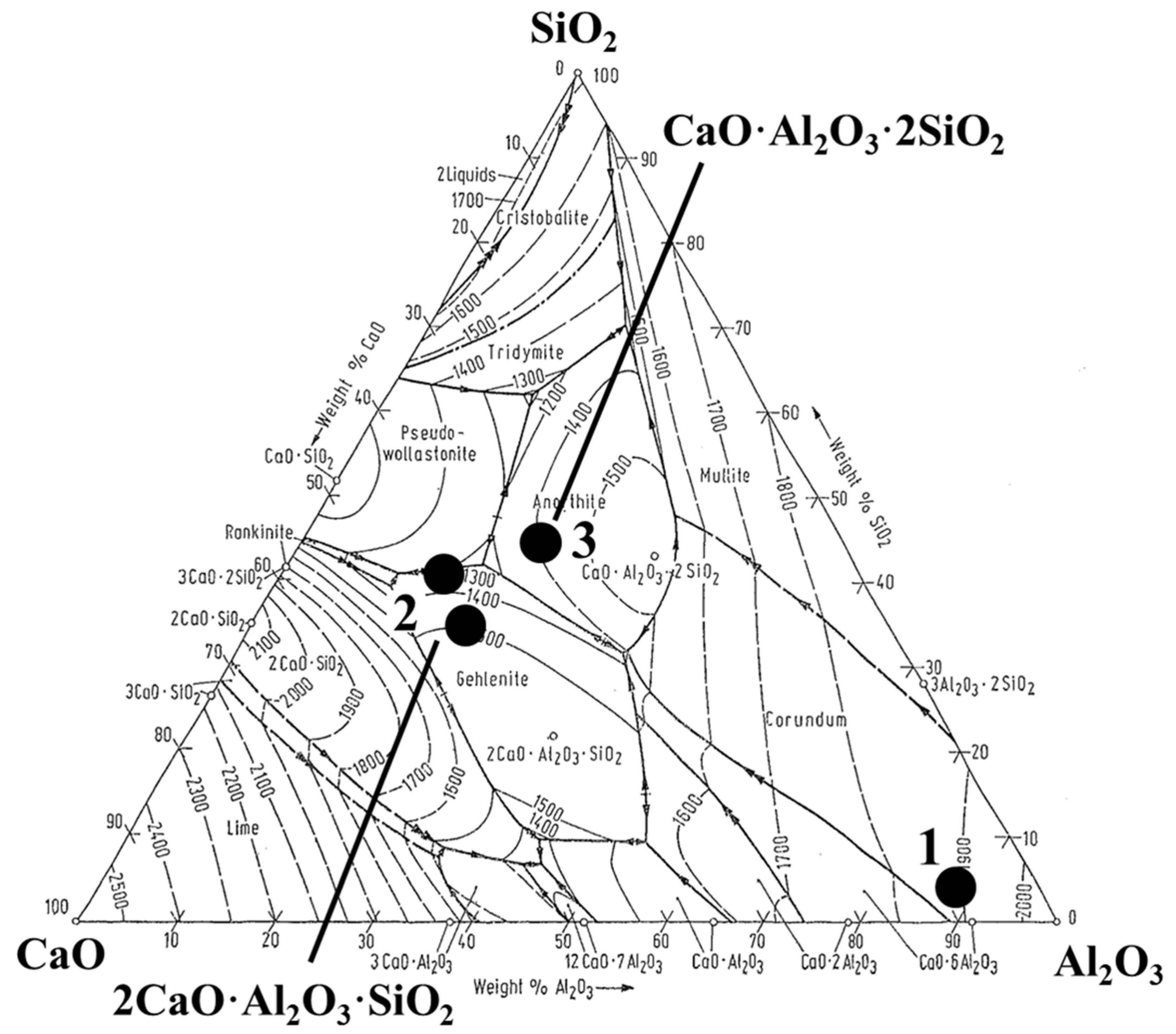
| Inclusion | Inclusion Stoichiometry | Hardness (kg/mm2) | Melting Temperature, Tm (°C) |
|---|---|---|---|
| Alumina | Al2O3 | 3000 | 2050 |
| Silicate | SiO2 | 1600 | 1720 |
| Calcium aluminates | (CaO)-(Al2O3) | 930 | 1330–1839 |
| Gehlenites | Ca2Al[AlSiO7] | 1200 | 1310–1590 |
| Anorthites | CaAl2Si2O8 | 850 | 1170–1550 |
5. Summary
Acknowledgments
Conflicts of Interest
References
- Thoors, H.; Chandrasekaran, H.; Ölund, P. Study of some active wear mechanisms in a titanium-based cermet when machining steels. Wear 1993, 162–164, 1–11. [Google Scholar] [CrossRef]
- Monnot, J.; Heritier, B.; Cogne, J.Y. Effect of Steel Manufacturing Process on the Quality of Bearing Steels; Hoo, J., Ed.; ASTM: Philadelphia, PA, USA, 1988; pp. 149–164. [Google Scholar]
- Jeon, S.-H.; Kim, S.T.; Lee, I.S.; Park, Y.S. Effects of sulfur addition on pitting corrosion and machinability behaviour of super duplex stainless steel containing rare earth metals: Part 2. Corros. Sci. 2010, 52, 3537–3547. [Google Scholar] [CrossRef]
- Tönshoff, H.K.; Stanske, C. High productivity machining: Materials and processes. In Proceedings of the International Conference on High Productivity Machining, Materials and Processing, New Orleans, LA, USA, 7–9 May 1985.
- Kirsch-Racine, A.; Bomont-Arzur, A.; Confente, M. Calcium treatment of medium carbon steel grades for machinability enhancement: From the theory to industrial practice. Rev. Métall. CIT 2007, 104, 591–597. [Google Scholar] [CrossRef]
- Ståhl, J.-E. Metal Cutting—Theories and Models; Division of Production and Materials Engineering, Lund University: Lund, Sweden, 2012; pp. 391–393. [Google Scholar]
- Ståhl, J.-E. Metal Cutting—Theories and Models; Division of Production and Materials Engineering, Lund University: Lund, Sweden, 2012; p. 105. [Google Scholar]
- Engineering Fundamentals. Available online: http://www.efunda.com/processes/machining/drill.cfm (accessed on 14 December 2014).
- Swedish Standard SS-ISO 8688–1: 1989 (E): Tool Life Test in Milling—Part 1: Face Milling; Swedish Standards Institution: Stockholm, Sweden, 1994.
- Swedish Standard SS-ISO 8688–2: 1989 (E): Tool Life Test in Milling—Part 2: End Milling; Swedish Standards Institution: Stockholm, Sweden, 1994.
- Ernst, H. Physics of metal cutting. In Machining of Metals; The American Society of Metals: Cleveland, OH, USA, 1938. [Google Scholar]
- Stephenson, D.A.; Agapiou, J.S. Metal Cutting Theory and Practice, 2nd ed.; CRC Press Taylor & Francis Group: Boca Raton, FL, USA, 2006. [Google Scholar]
- Kalpakjian, S. Manufacturing Processes for Engineering Materials; Addison-Wesley: Boston, MA, USA, 1984; p. 467. [Google Scholar]
- Kiessling, R. The influence of non-metallic inclusions on the properties of steel. J. Met. 1969, 21, 47–54. [Google Scholar]
- Mills, B.; Redford, A.H. Machinability of Engineering Materials; Applied Science Publishers: London, UK; New York, NY, USA, 1983; pp. 13–21. [Google Scholar]
- Swedish Standard, SS-ISO 3685:1993(E): Tool-Life Testing With Single-Point Turning Tools; Swedish Standards Institution: Stockholm, Sweden, 1994.
- Mills, B.; Redford, A.H. Machinability of Engineering Materials; Applied Science Publishers: London, UK; New York, NY, USA, 1983; pp. 11–12. [Google Scholar]
- Brooksbank, D.; Andrews, K.W. Production and application of clean steels. J. Iron Steel Inst. 1972, 210, 246. [Google Scholar]
- Samsonov, G.V. The Physical-Chemical Properties of Oxides; Metallurgy: Moscow, Russia, 1978; p. 130. [Google Scholar]
- Touloukian, Y.S. (Ed.) The Thermo-Physical Properties of High Temperatures of Solid Materials; Macmillan Co.: New York, NY, USA, 1967; Volume 4, p. 462.
- Dudnik, E.M.; Oganesyan, V.K. Thermal expansion of some sulfides of the transition metals. Porosk. Metall. 1966, 38, 60–62. [Google Scholar]
- Goryachev, Y.M.; Kutsenok, T.G. The coefficient of thermal expansion of alloyed cerium sulfide in the Ce2S3-Ce3S4 homogeneity region. Porosk. Metall. 1969, 77, 59–62. [Google Scholar]
- Material expansion coefficients. In Laser and Optics; Agilent Technologies: Santa Clara, CA, USA, 2002; pp. 17:6–17:9.
- Coefficient of Thermal Expansion for Various Materials at Different Temperatures; Technical Report TR-18(100-71-2), Rev. F/6/25/2004; Bal Seal Engineering Co.: Amsterdam, The Netherlands, 2004; pp. 1–6.
- Holappa, L.; Helle, A. Inclusion control in high-performance steels. J. Mater. Process. Technol. 1995, 53, 177–186. [Google Scholar] [CrossRef]
- Väinölä, R.; Holappa, L.; Karvonen, P. Modern steelmaking technology for special steels. J. Mater. Process. Technol. 1995, 53, 453–465. [Google Scholar] [CrossRef]
- Ollilainen, V. The effect of Calcium treatment on the machinability of steel. In Proceedings of the Swedish Symposium on Non-Metallic Inclusions in Steel, Hagfors, Sweden, 27–29 April 1981; pp. 429–449.
- Nordgren, A. Tool Wear and Inclusion Behaviour during Machining of Ca-Treated Steels. Licentiate Thesis, KTH Royal Institute of Technology, Stockholm, Sweden, May 1993. [Google Scholar]
- Wang, Y.-N.; Bao, Y.-P.; Wang, M.; Zhang, L.-C. Precipitation and control of BN inclusions in 42CrMo steel and their effect on machinability. Int. J. Miner. Metal. Mater. 2013, 20, 842–849. [Google Scholar] [CrossRef]
- Harju, E.; Kivivuori, S.; Korhonen, A. Formation of a wear resistant non-metallic protective layer on PVD-coated cutting and forming tools. Surf. Coat. Technol. 1999, 112, 98–102. [Google Scholar] [CrossRef]
- Svensson, S.; Nordgren, A.; Ollilainen, V. Material Characteristics and Machinability of Four Case-Hardening Steels; Report IM 26–6928; Swedish Institute for Metals Research: Stockholm, Sweden, 1984. [Google Scholar]
- Thoors, H.; Nordgren, A. Influence of Non-Metallic Inclusions on the Machinability of Four Case‑Hardening Steels in Turning—Metallographic Investigations; Report IM-2072; Swedish Institute for Metals Research: Stockholm, Sweden, 1986. [Google Scholar]
- Poulachon, G.; Dessoly, M.; Le Calvez, C.; Lebrun, J.L.; Prunet, V.; Jawahir, I.S. An investigation of the influence of sulphide inclusions on tool-wear in high speed milling of tool steels. Wear 2001, 250, 334–343. [Google Scholar] [CrossRef]
- Barry, J.; Byrne, G. Cutting tool wear in the machining of hardened steels Part 1: Alumina/TiC cutting tool wear. Wear 2001, 247, 139–151. [Google Scholar] [CrossRef]
- Zaslavskii, A.Y. Mechanism of improving the machinability of steel by inclusions. Metalloved. Term. Obrab. Metall. 1984, 9, 15–22. [Google Scholar]
- Mills, B.; Akhtar, S. A metallurgical and machining study of free machining and low carbon steels. In Influence of Metallurgy on Machinability; American Society for Metals: Geauga, OH, USA, 1975; pp. 73–88. [Google Scholar]
- Tasaka, K.; Akasawa, T.; Kuroiwa, K. Effect of oxides and sulfides on the machinability of steels. In Influence of Metallurgy on Machinability; American Society for Metals: Geauga, OH, USA, 1975; pp. 130–158. [Google Scholar]
- Ray, K.K.; Das, J.; Dixit, A.; Chakraborty, M.; Chakravorty, S.; Guha, S.N. Effect of cold deformation on the machinability of a free cutting steel. Mater. Manuf. Process. 2006, 21, 333–340. [Google Scholar] [CrossRef]
- Liu, H.; Chen, W. Effect of total oxygen content on the machinability of low carbon resulfurized free cutting steel. Steel Res. Int. 2012, 83, 1172–1179. [Google Scholar] [CrossRef]
- Lou, D.; Cui, K.; Jia, Y. Study on the machinability of resulfurized composite free-cutting steels. J. Mater. Eng. Perform. 1997, 6, 215–218. [Google Scholar] [CrossRef]
- Fang, X.D.; Zhang, D. An investigation of adhering layer formation during tool wear progression in turning of free-cutting stainless steel. Wear 1996, 197, 169–178. [Google Scholar] [CrossRef]
- Bletton, O.; Duet, R.; Pedarre, P. Influence of oxide nature on the machinability of 316L stainless steel. Wear 1990, 139, 179–193. [Google Scholar] [CrossRef]
- Tian, Y.; Li, Z. The influence of alloying additives on the machinability of austenitic stainless steels. Adv. Mater. Res. 2011, 189–193, 23–30. [Google Scholar] [CrossRef]
- ASM Handbook. Machinability of steels, properties and selection. In Irons, Steels, and High-Performance Alloys; ASM International: Geauga, OH, USA, 1990; pp. 591–602. [Google Scholar]
- Sims, C.E.; Dahle, F.B. The effect of aluminum on the properties of medium carbon cast steel. Trans. Am. Foundrym. Soc. 1938, 46, 65–132. [Google Scholar]
- Sims, C.E. The nonmetallic constituents of steel. Trans. Met. Soc. AIME 1959, 215, 367–393. [Google Scholar]
- Steinmetz, E.; Lindenberg, H.-U. Einfluß von Kohlenstoff, Silicium und Aluminium auf die Morphologie der Sulfide in Eisenwerkstoffen. Arch. Eisenhűttenwes. 1976, 47, 713–718. [Google Scholar]
- Itzkovich, G.M. Deoxidation of Steel and Modification of Nonmetallic Inclusions; Metallurgia: Moscow, Russia, 1981; p. 296. [Google Scholar]
- Karasev, A.; Inoue, R.; Tilliander, A.; Jönsson, P.G. Application of electrolytic extraction for three-dimensional investigation of inclusion characteristics in the steelmaking area. In ISIJ-VDEh-Jernkontoret Joint Symposium—14th VDEh-ISIJ Seminar on Science and Technology of Process Metallurgy, Proceedings of the 8th Japan-Nordic Countries Joint Symposium on Science and Technology of Process Metallurgy, Osaka, Japan, 15–16 April 2013; pp. 1–5.
- Karasev, A.; Bi, Y.; Jönsson, P. Three-Dimensional Investigation of Large-Size Inclusions and Clusters in Steels by Using the Electrolytic Extraction Technique. In AISTech-2013,Proceedings of the Iron and Steel Technology Conference, Pittsburgh, PA, USA, 6–9 April 2013; pp. 1–7.
- Niklasson, G. Standardized milling test. In Proceedings of the 3rd International MTDR Conference, Birmingham, UK, September 1962; Pergamon Press: Oxford, UK, 1963. [Google Scholar]
- Wranglen, G. Pitting and sulphide inclusions in steel. Corros. Sci. 1974, 14, 331–349. [Google Scholar] [CrossRef]
- Webb, E.G.; Suter, T.; Alkire, R.C. Microelectrochemical measurements of the dissolution of single MnS inclusions, and the prediction of the critical conditions for pit initiation on stainless steel. J. Electrochem. Soc. 2001, 148, B186–B195. [Google Scholar] [CrossRef]
- Williams, D.E.; Zhu, Y.Y. Explanation for initiation of pitting corrosion of stainless steels at sulfide inclusions. J. Electrochem. Soc. 2000, 147, 1763–1766. [Google Scholar] [CrossRef]
- Ha, H.Y.; Park, C.J.; Kwona, H.S. Effects of misch metal on the formation of nonmetallic inclusions and the associated resistance to pitting corrosion in 25% Cr duplex stainless steels. Scr. Mater. 2006, 55, 991–994. [Google Scholar] [CrossRef]
- Nicholson, A.; Gladman, T. Non-metallic inclusions and developments in secondary steelmaking. Ironmak. Steelmak. 1986, 13, 53–69. [Google Scholar]
- Leung, C.-H.; van Vlack, L. Solubility limits in binary (Ca,Mn) chalcogenides. J. Am. Ceram. Soc. 1979, 62, 613–616. [Google Scholar] [CrossRef]
- Jehan, M. Calcium metal granules injection in steel ladles—advantages, technological and metallurgical conditions and results in free silicon and special steels. In Scaninject 4—Part 2; MEFOS: Luleå, Sweden, 1986; pp. 26:1–26:27. [Google Scholar]
- Herbert, A.; Notman, G.K.; Morris, D.; Knowles, S.; Jemson, C. Experiences with powder and wire injection at british steel corporation, lackenby works, basic oxygen steelmaking plant. In Scaninject 4—Part 2; MEFOS: Luleå, Sweden, 1986; pp. 27:1–27:36. [Google Scholar]
- Kiessling, R. Non-Metallic Inclusions in Steel—Part V; The institute of metals: London, UK, 1989; p. 51. [Google Scholar]
- Nordgren, A.; Melander, A. Deformation behaviour of different types of inclusion during chip formation in turning of quenched and tempered steels. Mater. Sci. Technol. 1989, 5, 940–951. [Google Scholar] [CrossRef]
- Lu, W.K.; McLean, A. Thermodynamic behaviour of rare-earth elements in molten steel. Ironmak. Steelmak. 1974, 8, 228–237. [Google Scholar]
- Wilson, W.; Wells, R. Identifying inclusions in rare earth treated steels. Metal Prog. 1973, 104, 75–77. [Google Scholar]
- Wang, L.-M.; Lin, Q.; Yue, L.-J.; Liu, L.; Guo, F.; Wang, F.-M. Study of application of rare earth elements in advanced low alloy steels. J. Alloys Comp. 2008, 451, 534–537. [Google Scholar] [CrossRef]
- Waudby, P.E. Rare earth additions to steel. Int. Met. Rev. 1978, 23, 74–98. [Google Scholar] [CrossRef]
- Kang, S.K.; Gow, K.V. Mechanical properties of rare earth treated rail steels. Met. Trans. A 1979, 10A, 1800. [Google Scholar] [CrossRef]
- Kang, S.K.; Gow, K.V. Improved fatigue strength of rare earth metal treated axle steel. Met. Trans. A 1981, 12A, 907–910. [Google Scholar] [CrossRef]
- Väinölä, R.; Karvonen, P.; Helle, L.W. Establishment of Calcium treatment practices at Ovako—Historical development and evaluation of alternative methods. In Scaninject 4—Part 2; MEFOS: Luleå, Sweden, 1986; pp. 23:1–23:20. [Google Scholar]
- Larsson, A.; Ruppi, S. Structure and composition of built-up layers on coated tools during turning of Ca-treated steel. Mater. Sci. Eng. 2001, A313, 160–169. [Google Scholar] [CrossRef]
© 2015 by the authors; licensee MDPI, Basel, Switzerland. This article is an open access article distributed under the terms and conditions of the Creative Commons Attribution license (http://creativecommons.org/licenses/by/4.0/).
Share and Cite
Ånmark, N.; Karasev, A.; Jönsson, P.G. The Effect of Different Non-Metallic Inclusions on the Machinability of Steels. Materials 2015, 8, 751-783. https://doi.org/10.3390/ma8020751
Ånmark N, Karasev A, Jönsson PG. The Effect of Different Non-Metallic Inclusions on the Machinability of Steels. Materials. 2015; 8(2):751-783. https://doi.org/10.3390/ma8020751
Chicago/Turabian StyleÅnmark, Niclas, Andrey Karasev, and Pär Göran Jönsson. 2015. "The Effect of Different Non-Metallic Inclusions on the Machinability of Steels" Materials 8, no. 2: 751-783. https://doi.org/10.3390/ma8020751