Article

Influence of Orientation and Radiative Heat Transfer on Aluminum Foams in Buoyancy-Induced Convection

Department of Flow, Heat and Combustion Mechanics, Ghent University, Sint-Pietersnieuwstraat 41, Ghent 9000, Belgium
*
Author to whom correspondence should be addressed.
Materials 2015, 8(10), 6792-6805; https://doi.org/10.3390/ma8105340
Submission received: 30 July 2015 / Revised: 21 September 2015 / Accepted: 23 September 2015 / Published: 9 October 2015
(This article belongs to the Special Issue Metal Foams: Synthesis, Characterization and Applications)

Abstract

:
Two differently-produced open-cell aluminum foams were compared to a commercially available finned heat sink. Further, an aluminum plate and block were tested as a reference. All heat sinks have the same base plate dimensions of four by six inches. The first foam was made by investment casting of a polyurethane preform and has a porosity of 0.946 and a pore density of 10 pores per linear inch. The second foam is manufactured by casting over a solvable core and has a porosity of 0.85 and a pore density of 2.5 pores per linear inch. The effects of orientation and radiative heat transfer are experimentally investigated. The heat sinks are tested in a vertical and horizontal orientation. The effect of radiative heat transfer is investigated by comparing a painted/anodized heat sink with an untreated one. The heat flux through the heat sink for a certain temperature difference between the environment and the heat sink’s base plate is used as the performance indicator. For temperature differences larger than 30 C, the finned heat sink outperforms the in-house-made aluminum foam heat sink on average by 17%. Furthermore, the in-house-made aluminum foam dissipates on average 12% less heat than the other aluminum foam for a temperature difference larger than 40 C. By painting/anodizing the heat sinks, the heat transfer rate increased on average by 10% to 50%. Finally, the thermal performance of the horizontal in-house-made aluminum foam heat sink is up to 18% larger than the one of the vertical aluminum foam heat sink.

1. Introduction

Electronic components are omnipresent in daily life products, such as cars, computers and power converters. Hence, it is important to reduce the chance of premature electronics failure. The main causes of electronics failure are over-voltage, elevated operating temperature, moisture and electrostatic discharge (ESD) [1]. To avoid failures caused by elevated operating temperatures, electronic components are cooled. Besides the increased lifetime, some components, such as LEDs, are also more efficient at lower operating temperatures [2,3,4].
Due to the miniaturization of electronic devices and the resulting rise of heat fluxes [5,6], electronic devices need to be cooled by heat sinks. Two types of heat sinks can be distinguished: passive and active heat sinks. The passive heat sink dissipates heat by buoyancy-induced convection. The active heat sink is equipped with a fan to induce an air flow through it and thereby dissipates heat by forced convection. From an economic and ecological point of view, passive heat sinks are favorable over active heat sinks, because they are less expensive, more reliable, require less maintenance and do not use energy.
Current heat sinks use fins to increase their surface-to-volume ratio. These fin shapes can become quite complex, e.g., three-dimensional surface extensions [7,8,9]. One promising material that can be used as three-dimensional surface extensions is high-porous open-cell metal foam.
Open-cell metal foam is a porous media that has a very high volumetric porosity ϕ which is defined as:
ϕ = V total - V solid V total
The volumetric porosity is typically larger than 0.85. A high porosity will be beneficial for mobile applications due to the reduced weight of the heat sink.
The structure of high-porous open-cell metal foam can be found in Figure 1. The metal foam consists of cells that are connected through pores. Each cell is made of several struts, which connect in the nodes. The cell size of metal foam is commonly given as the pores per linear inch (PPI)-value. The porosity ϕ and the PPI-value are typically used to characterize open-cell metal foam in the literature. Nevertheless, other methods for characterizing metal foam exist [10].
Figure 1. The structure of open-cell metal foam.
Materials 08 05340 g001
The work of Ashby [11], Banhart [12] and Dukhan [13] describes the different production methods of open-cell metal foam. Two methods that are relevant to this work are investment casting of a polymer foam precursor and leachable bed casting. A product example of each production method is shown in Figure 2. In the first method, an open-cell polymer foam is made by reticulation of a polyurethane foam [14]. Then, the investment casting technique is used to make an exact metallic copy of this open-cell polymer foam. In the second method, metal is cast over a stacked bed of solvable spheres, e.g., salt spheres or sand with a polymer bonding agent [15]. After solidification, these spheres are removed.
Figure 2. An example of a metal foam produced by (a) investment casting of a polymer foam precursor and (b) leachable bed casting.
Materials 08 05340 g002
To date, metal foam used in forced convection is extensively described in the literature [16,17,18]. However, open literature considering buoyancy-induced convection is limited.
Aluminum foam in buoyancy-induced convection was first investigated by Bhattacharya et al. [19]. The authors tested different aluminum foam heat sinks in a horizontal and vertical orientation. Furthermore, their finned aluminum foam heat sink was compared to a commercially available finned heat sink. Qu et al. [20] developed a heat transfer correlation for copper foam in buoyancy-induced convection at an arbitrary orientation. Besides the orientation, the correlation also included the effects of the foam structure and the height of the heat sink. Recently, De Schampheleire et al. [21,22] investigated the influences of porosity, pore size, foam height and radiative heat transfer on the thermal performance of aluminum foam heat sinks in buoyancy-induced convection, both numerically and experimentally. Based on these results published in the open literature, the following conclusions can be drawn:
The heat transfer of highly-porous metal foam in buoyancy-induced convection increases with decreasing porosity [19,20,21];
The heat transfer of highly porous metal foam in buoyancy-induced convection decreases with increasing pore density [19,20,21];
The heat dissipated by the metal foam heat sink increases with increasing heat sink height until it reaches an asymptotic value. The asymptotic value is reached when the effect of the increasing viscous drag and the temperature drop along the heat sink’s height equals the effect of increasing surface area [20,21];
De Schampheleire et al. [22] indicated the importance of the radiative heat transfer of metal foam heat sinks in buoyancy-driven convection. The authors found that up to 30% of the total heat transfer of aluminum foam heat sinks in buoyancy-induced convection is due to thermal radiation;
The experimental data of both Bhattacharya et al. [19] and Qu et al. [20] suggest a non-significant effect of the orientation on the thermal performance of metal foam heat sinks.
The first aim of this study is to compare the thermal performance of an aluminum foam heat sink made by investment casting of a polymer precursor, an aluminum foam heat sink made by leachable bed casting and a finned heat sink in buoyancy-induced convection. To the best of our knowledge, an experimental comparison between a finned heat sink and an aluminum foam heat sink has not yet been done. Bhattacharya et al. [19] only compared a finned metal foam heat sink with the correlation of an optimal finned heat sink and concluded that the finned metal foam heat sink performed better. Further, the influence of thermal radiation on buoyancy-induced convection is investigated. In contrast to the work that has already been done, the influence of the foam production method and the height of the foam was investigated. Finally, this paper investigated the influence of the heat sink’s orientation on its thermal performance.

2. Methodology

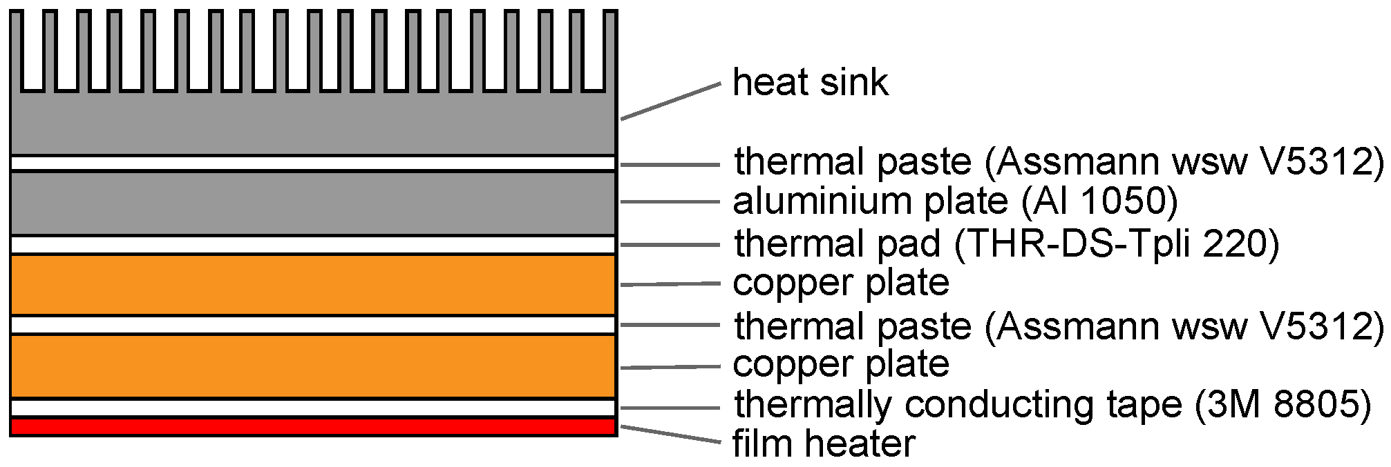
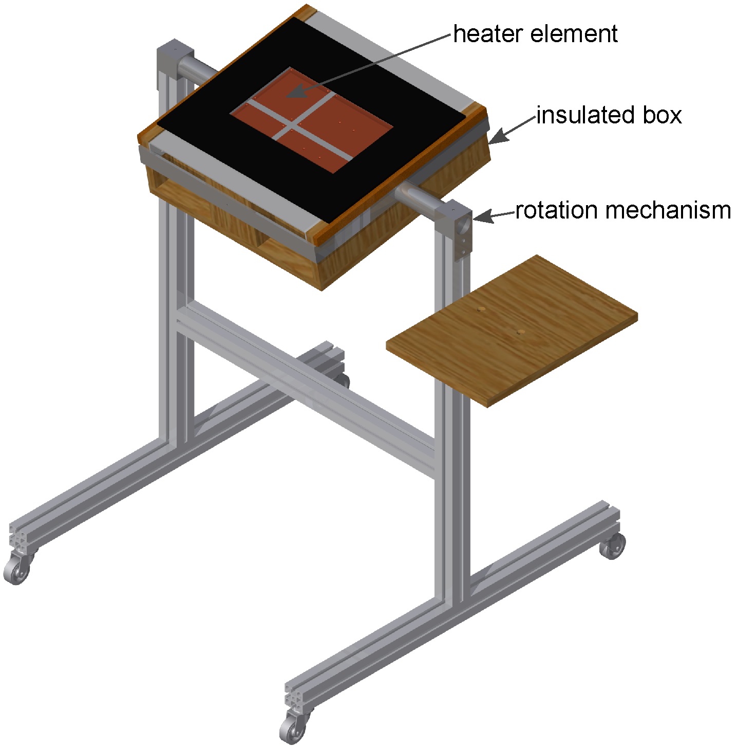
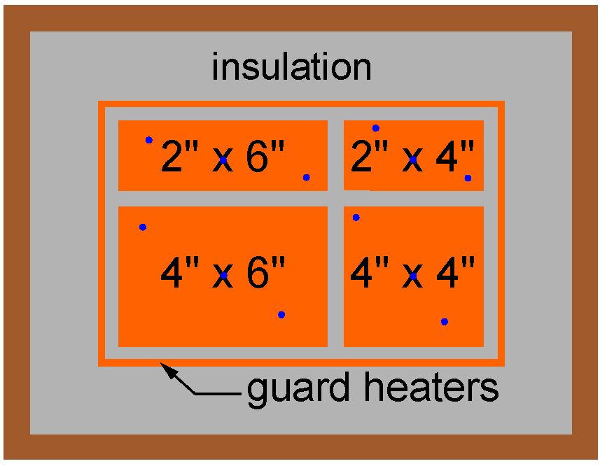
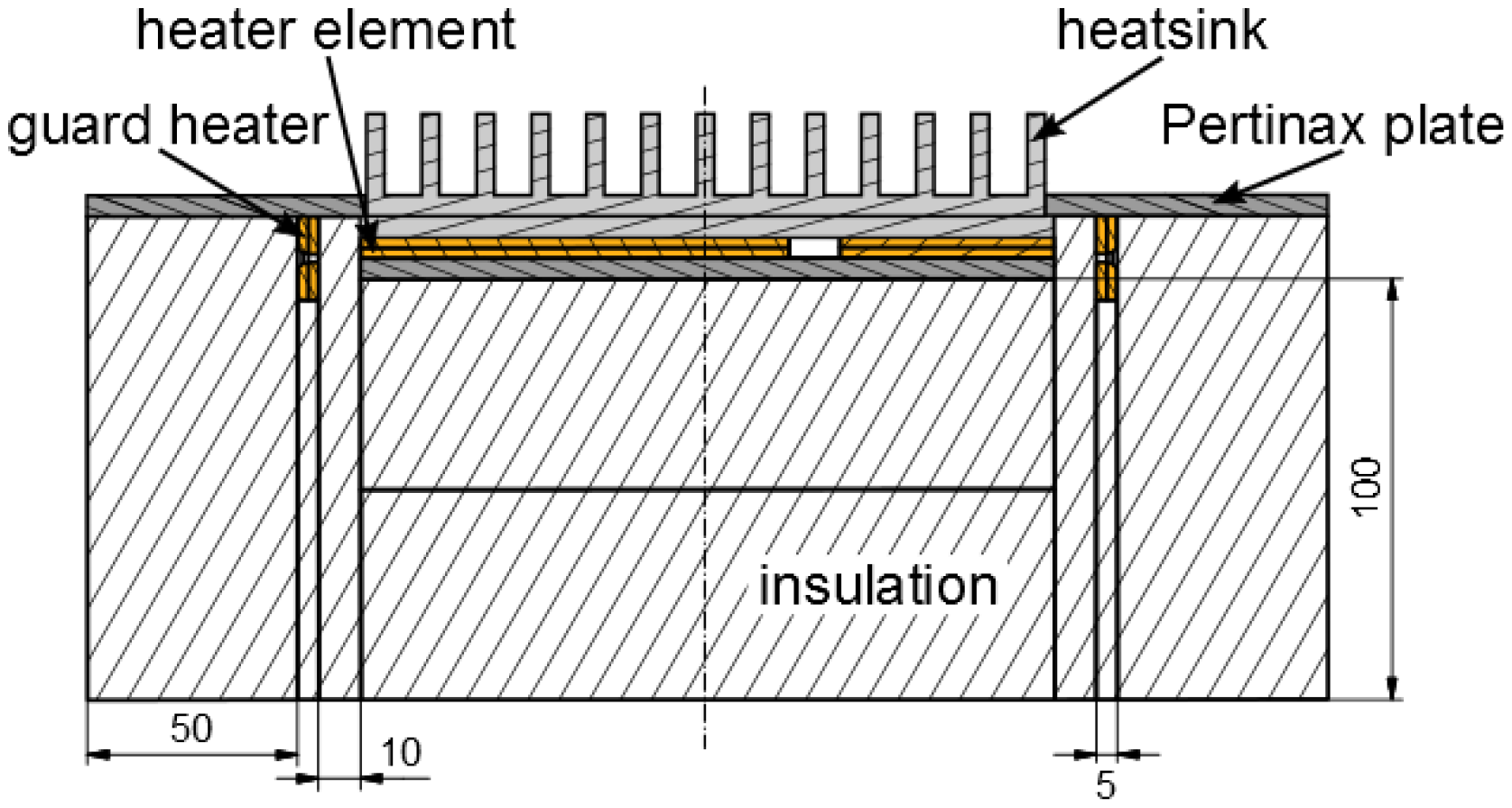
2.1. Experimental Setup
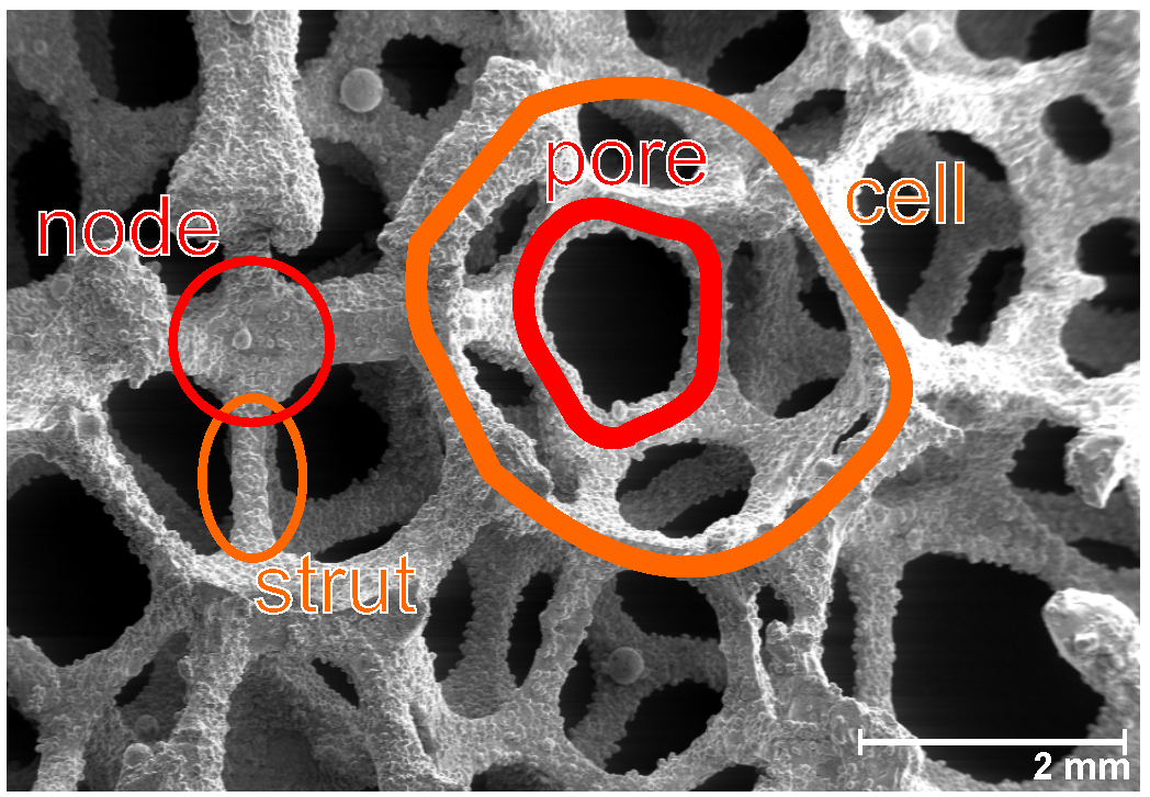
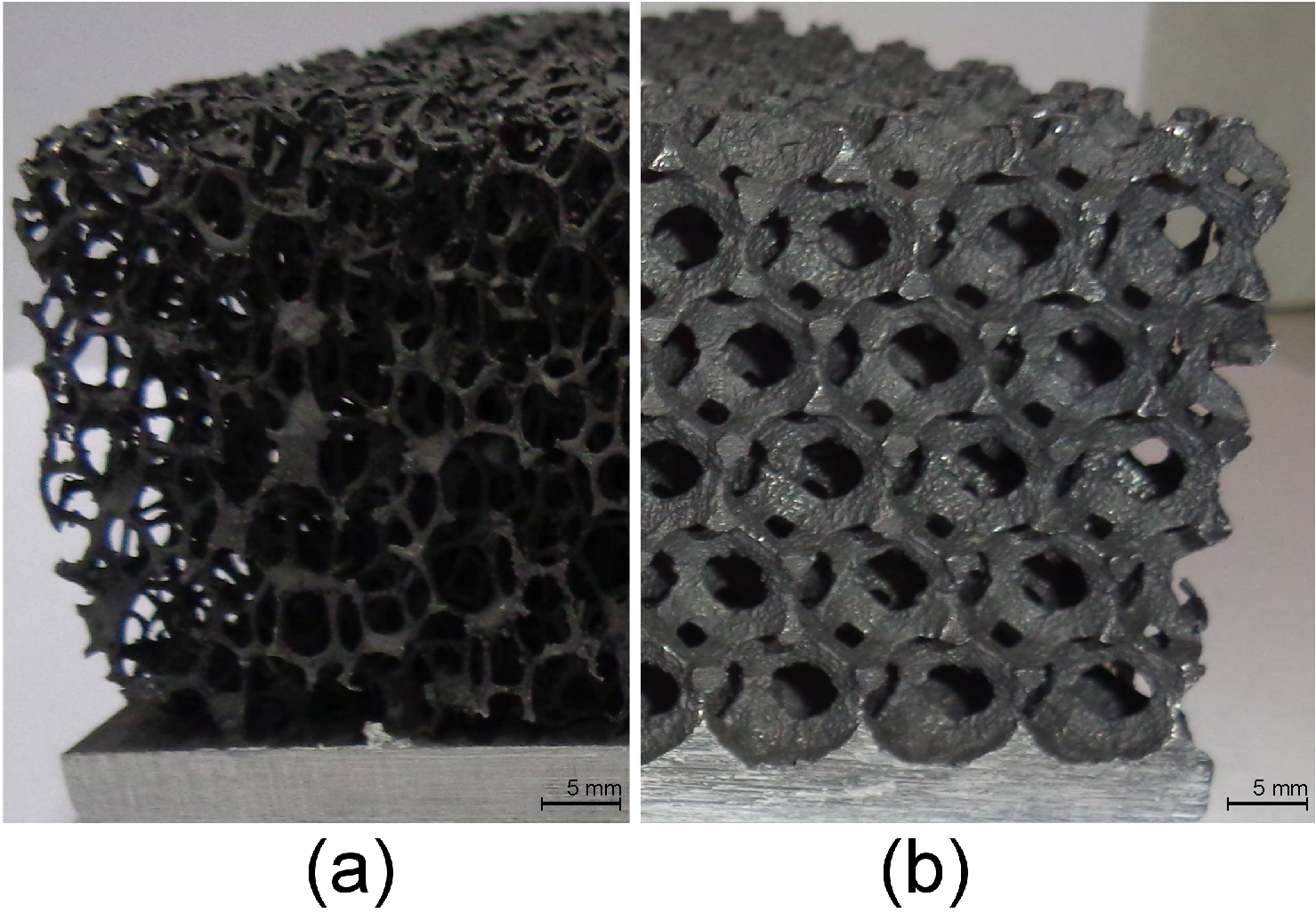
No standardized methodology exits for testing heat sinks in buoyancy-induced convection. Hence, the design of the experimental setup was based on experimental setups found in the literature [19,20,21,23,24]. The design of the experimental setup aimed to achieve a one-dimensional heat flux through the heat sink.
The experimental setup, depicted in Figure 3, consists of a frame, a rotation mechanism and an insulated box. The rotation mechanism enables the setup to test the heat sinks in different orientations.
Figure 4 and Figure 5 are a top view and a cross-section of the insulated box, respectively. To test different heat sink sizes in future work, four heater elements with different dimensions are placed in an array. The heat sink that will be tested is placed on top of one or multiple heater elements. In the current study, only the 4″ × 6″ heater element was used.
Figure 3. Overview of the experimental setup.
Materials 08 05340 g003
Figure 4. Top view of the insulated box. The blue dots indicate the locations of the thermocouples.
Materials 08 05340 g004
Figure 5. A cross-section of the insulated box.
Materials 08 05340 g005
Figure 6 represents the cross-section of one of the four heater elements. This heater element consists of a stack of metal plates and an electrical film heater (Omega® KH series, OMEGA Engineering, Inc., Stamford, CT, USA). The two copper plates ensure a uniform temperature distribution at the base plate of the heat sink, resulting in a uniform heat flux through the base plate. The uniform temperature distribution was verified using an IR-camera. The temperature uniformity was within the uncertainty of the camera. The copper plates are also used to fix the thermocouples in between them. The aluminum plate is added to compensate for different base plate thicknesses. Further, layers of thermal paste (k = 0.8 W/(m.K)) and thermal pads (k = 6 W/(m.K)) are added in between to avoid insulating air gaps between the metal plates. The two largest and the two smallest electrical film heaters are each respectively powered by an Elektro Automatik® PS 8160-04 2U (Helmholtzstrasse, Germany) and a TTi® PLH120-P (Fort Worth, TX, USA).
As depicted in Figure 5, guard heaters are only used at the sides, while the bottom surfaces of the heater elements are well insulated. The insulation material used is Microtherm (k = 0.0221 W/(m.K)). Below the main heaters, there is 100 mm of insulation. The thickness of insulation next to the guard heaters is 50 mm and in between the guard and main heater there is 10 mm of insulation.
Figure 6. Cross-section of a heater element.
Materials 08 05340 g006
The side guard heaters consist of 2 copper plates and an electrical film heater (Omega® KHLV series). These side guard heaters are powered by a TTi® PL303QMD-P. When only part of the main heaters is used, which is the case in this study, the other heater elements serve as extra guard heaters.
The heat sink is firmly pressed against the heaters by a 5 mm-thick plate of Pertinax® (k = 0.2 W/(m.K)), as shown in Figure 5. In addition, this plate forms one smooth surface with the base plate of the heat sink to avoid any disturbance of the air flow.
The temperature of each heater element is measured by 3 K-type thermocouples ( D j = 0.5 mm) and the temperature of each side guard heater is measured by 2 K-type thermocouples ( D j = 0.5 mm). In both cases, the thermocouples are placed between the two copper plates (Figure 5 and Figure 6) into a machined slot of 0.5 mm, which is not visible on the figure. The ambient temperature is measured by 4 K-type thermocouples ( D j = 0.75 mm). These 4 thermocouples are placed at the four corners of the experimental setup at a height of 15 cm above the Pertinax® plate (Fibox, Espoo, Finland). All thermocouples are read out by a data acquisition system (Keithley® 2700, Keithley Instruments Inc., Cleveland, OH, USA).

2.2. Test Samples

Table 1 lists the tested heat sinks. All tested heat sinks have the same base plate dimensions (4″ × 6″). First, a flat aluminum plate (= bare base plate) and two solid aluminum blocks were tested. Further, two different aluminum foams were tested. The first aluminum foam (reticulated22 and reticulated40) was made in-house by investment casting of a polymer foam precursor. This aluminum foam has a very high porosity (94.6%) and a moderate PPI-value (10 PPI). Both values are given by the manufacturer. The average cell diameters measured in two perpendicular directions are respectively 3.4 mm and 4.8 mm. The measured pore density is 6 PPI in one direction and 8 PPI in the perpendicular direction. This value is lower than specified by the manufacturer. The second aluminum foam tested (spheres40) was bought from Alveotec® (Venissieux, France) [25]. This foam was produced using leachable bed casting. This foam has a relatively low porosity (85%) and PPI-value (2.5 PPI). Both values are given by the manufacturer. The average cell diameters measured in two perpendicular directions are respectively 8.1 mm and 8.3 mm. The measured pore density is 2.5 PPI in one direction and 2.6 PPI in the perpendicular direction. Although the Alveotec heat sink consists only of 4 pores in the height direction, the heat sink is representative for the Alveotec foam properties. Brun [26] demonstrated that 4 pores in every direction are enough to construct a representative elementary volume for thermo-hydraulic calculations. For constructing the aluminum foam heat sinks, the aluminum foam was glued onto the base plate using thermal conductive epoxy (Loctite® ESP110, Düsseldorf, Germany). Finally, a finned heat sink (Type S120), which was produced by Aavid® (Aavid Thermalloy, Laconia, NH, USA) [27], was also put to the test. After the first experiments, all heat sinks, except the finned heat sink, were painted with Kontakt Chemie® (Jena, Germany) Graphit 33. For the finned heat sink, an anodized version was bought and tested.
Table 1. Overview of the test samples.
NameWidth (mm)Length (mm)Height (mm)# FinsPorosity (-)PPIσ (m 2 /m 3 )Material
plate150.3 ± 0.05101.4 ± 0.050----Al 1050
block22150.0 ± 0.0599.0 ± 0.0522.0 ± 0.05-0-79Al 1050
block40150.0 ± 0.0599.0 ± 0.0540.0 ± 0.05-0-59Al 1050
reticulated22150.0 ± 0.05100.9 ± 0.0522.2 ± 0.05-0.94610486Al 1050
reticulated40149.3 ± 0.05101.0 ± 0.0540.0 ± 0.05-0.94610486Al 1050
spheres40 [25]149.8 ± 0.0597.5 ± 0.0540.0 ± 0.05-0.852.5360Al 1050
finned22 [27]150.0 ± 0.05101.0 ± 0.0522.0 ± 0.05250.65-352Al 6060

2.3. Measuring Procedure

First, the temperature difference between the heat sink’s base plate and the ambient air was set between 10 C and 70 C. Then, the side guard heaters’ temperature was controlled to the average temperature of the heat sink’s base plate using a PID-controller. Finally, when the steady state was reached, the power dissipated by the heat sink was measured as a function of the temperature difference between the base plate of the heat sink and the ambient air. Steady state was attained when the standard deviation of 100 temperature measurements of the heat sink’s base plate at a sampling frequency of 0.17 Hz was below 0.02 K. Some of the experiments were repeated to confirm the consistency of the experimental results.
The results are reported as the heat dissipated by the heat sink as a function of the temperature difference between the heat sink’s base plate and the ambient air. This is used as a measure for the thermal performance of the heat sink. For the Alveotec® foam heat sink, the heat dissipated by the heat sink per base plate surface area was also calculated to compensate for the small differences in base plate dimensions.

2.4. Uncertainty Analysis

The uncertainty analysis used in this work follows the textbook of Taylor [28].
The dimensions of all components are measured using a caliper with an accuracy of 0.05 mm.
All thermocouples are calibrated using a dry-block calibrator (Druck® DBC 150, Rho, Italy) and a reference thermometer (Fluke® 1523, Everett, WA, USA). After calibration, the average uncertainty of the thermocouples is ±0.11 C., and the maximum uncertainty is ±0.2 C.
Q hs = P e - Q loss
Equation (2) gives the power dissipated by the heat sink. The power supplied by the electrical heaters ( P e ) is measured internally by the power supplies. The relative uncertainty of the power measurement depends on the actual power, which is measured and ranges between 4.7% (at 5 W) and 1.5% (at 50 W).
The heat loss through the insulation ( Q loss ) is estimated using a 3-dimensional finite elements conduction model. The geometry used in the model resembles the actual experimental setup, shown in Figure 5. Two parts were simplified in the model’s geometry. First, the heater elements were replaced by a solid block of copper at a constant temperature. Further, the tested heat sink was modeled as a flat plate with an equivalent convection coefficient. At the other boundaries, a fixed convection coefficient of 5 W/K was assumed. The free air temperature was set to 20 C, which was comparable to the real testing conditions. To verify the estimation of the heat loss, the results of the aluminum plate experiments were compared to correlations from the literature [29,30] (see Figure 7).
Figure 7. A comparison between a painted flat plate in horizontal and vertical orientation with the correlation found in the literature [29,30].
Materials 08 05340 g007

3. Results and Discussion

First, the thermal performance of the in-house-made aluminum foam heat sink was compared to that of the finned heat sink and of the solid aluminum block. Later, a comparison between the in-house-made aluminum foam and the Alveotec® foam was made. Then, the influence of painting was investigated. Finally, the effect of orientation on the thermal performance was studied.

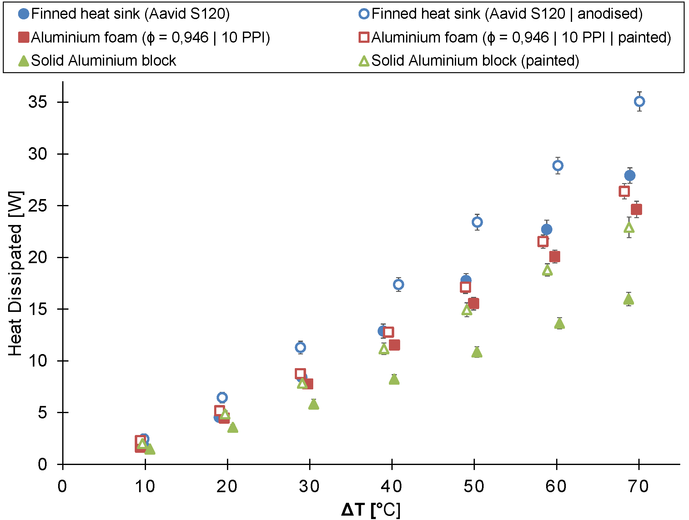
3.1. Comparison to Commercial Finned Heat Sink

The in-house-made aluminum foam heat sink (reticulated22) was compared to the finned heat sink (Aavid® S120) and the solid aluminum block in buoyancy-induced convection. All three tested heat sinks have the same height of 22 mm. Figure 8 shows the heat dissipated by the heat sink as a function of the temperature difference between the heat sink’s base plate and the ambient air for all three heat sinks.
Figure 8. The heat dissipated by the untreated and the painted/anodized heat sink as a function of the temperature difference between the ambient air and the heat sink’s base plate (heat sink’s height = 22 mm).
Materials 08 05340 g008
If the temperature difference is below 40 C, no significant difference exists between the heat dissipated by the finned and the aluminum foam heat sink. However, the heat dissipated by the finned heat sink is on average 17% larger for a temperature difference higher than 40 C. Both the finned and the aluminum foam heat sink clearly outperform the solid aluminum block, except for the lowest temperature difference measured.
The possible performance gain due to the higher surface-to-volume ratio (Table 1) of the aluminum foam heat sink compared to the finned heat sink is not found in the experimental results due to the higher hydraulic resistance of the aluminum foam heat sink.
The difference in performance between the finned and foamed heat sink (reticulated22) is explained by considering the smoke visualizations in Figure 9. The same technique was also used by Taji et al. [31] to visualize the air flow through a heat sink. In Figure 9, smoke generated by burning incense is used to visualize the air flow through the finned and aluminum foam heat sink. The smoke enters both heat sinks at the same location, i.e., at the side near the base plate. However, the exit location differs. In the finned heat sink, the smoke exits at the center of the heat sink. In the case of the aluminum foam heat sink, the smoke exits at the top of the heat sink before it reaches the heat sink’s center. After exiting the aluminum foam heat sink, the smoke deflects to the center to rise due to a chimney effect. Due to this deflection, cold air cannot enter the heat sink at the top; thus, no multi-chimney pattern [8] is formed. Hence, only part of the heat exchanging surface area of the aluminum foam adds to the convective heat transfer. Due to the higher hydraulic resistance of metal foam compared to fins, the heat exchanging surface area of foams is used less efficiently than in finned heat sinks. This explains why the metal foam, even though having a larger surface-to-volume ratio (see Table 1), has a smaller thermal performance than the finned heat sink. This shallow penetration by the air in the metal foam was also reported by De Schampheleire et al. [22], who performed numerical simulations. Moreover, a higher temperature difference induces a larger buoyancy force, but the air flow rate through the metal foam will increase less than the one of the finned heat sink, due to its higher hydraulic resistance. This will lower the local convection coefficient.
Figure 9. Visualization of the air flow through (a) the finned heat sink (Aavid ® S120) and (b) the in-house-made aluminum foam heat sink (reticulated22) using smoke ( Δ T = 70 C, horizontal orientation).
Materials 08 05340 g009

3.2. Comparison between the Alveotec® and the In-House-Made Aluminum Foam

Figure 10 compares the thermal performance of the in-house-made foam (reticulated40) to that of the Alveotec® foam (spheres40) [25]. The figure shows the heat dissipated by the heat sink as a function of the temperature difference between the heat sink’s base plate and the ambient air.
At temperature differences below 50 C, no significant difference in thermal performance exists between the Alveotec® and the in-house-made foam. Nevertheless, at larger temperature differences, the Alveotec® foam heat sink dissipates up to 12% more heat than the in-house-made aluminum foam heat sink. These results were expected based on the conclusions of previous studies [19,20,21]. These previous studies concluded that the thermal performance of metal foam in buoyancy-induced convection increased with decreasing porosity and PPI-value. A lower PPI-value results in larger pores and, thus, a lower hydraulic resistance, but also a lower surface-to-volume ratio. However, this decrease is partly compensated by the decrease of porosity, which increases the surface-to-volume ratio. Moreover, in buoyancy-induced convection, the hydraulic resistance has to be overcome by a small buoyancy force. Hence, a low hydraulic resistance has probably the most important influence on the thermal performance. Finally, it has to be noted that the in-house-made metal foam was bonded to the base plate using thermal conductive epoxy. This can lead to a higher contact resistance, thereby decreasing the thermal performance [32] according to De Schampheleire et al. [21], the influence of contact resistance is relatively low (<5%) in buoyancy-induced convection.
Figure 10. The heat dissipated by the unpainted and painted heat sink as a function of the temperature difference between the ambient air and the heat sink’s base plate (heat sink’s height = 40 mm).
Materials 08 05340 g010

3.3. Radiative Heat Transfer
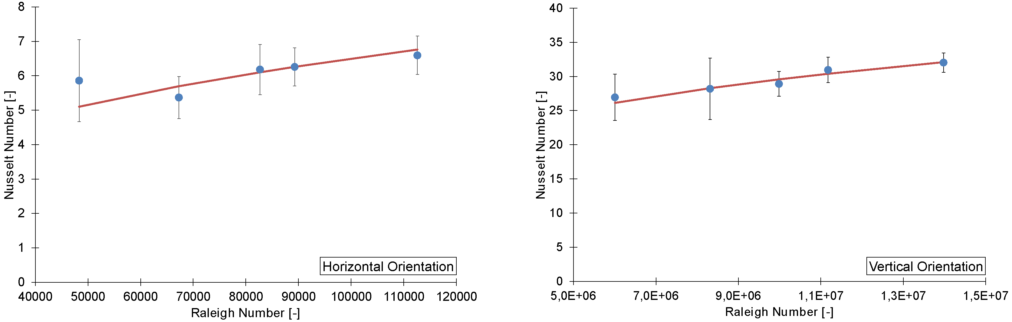
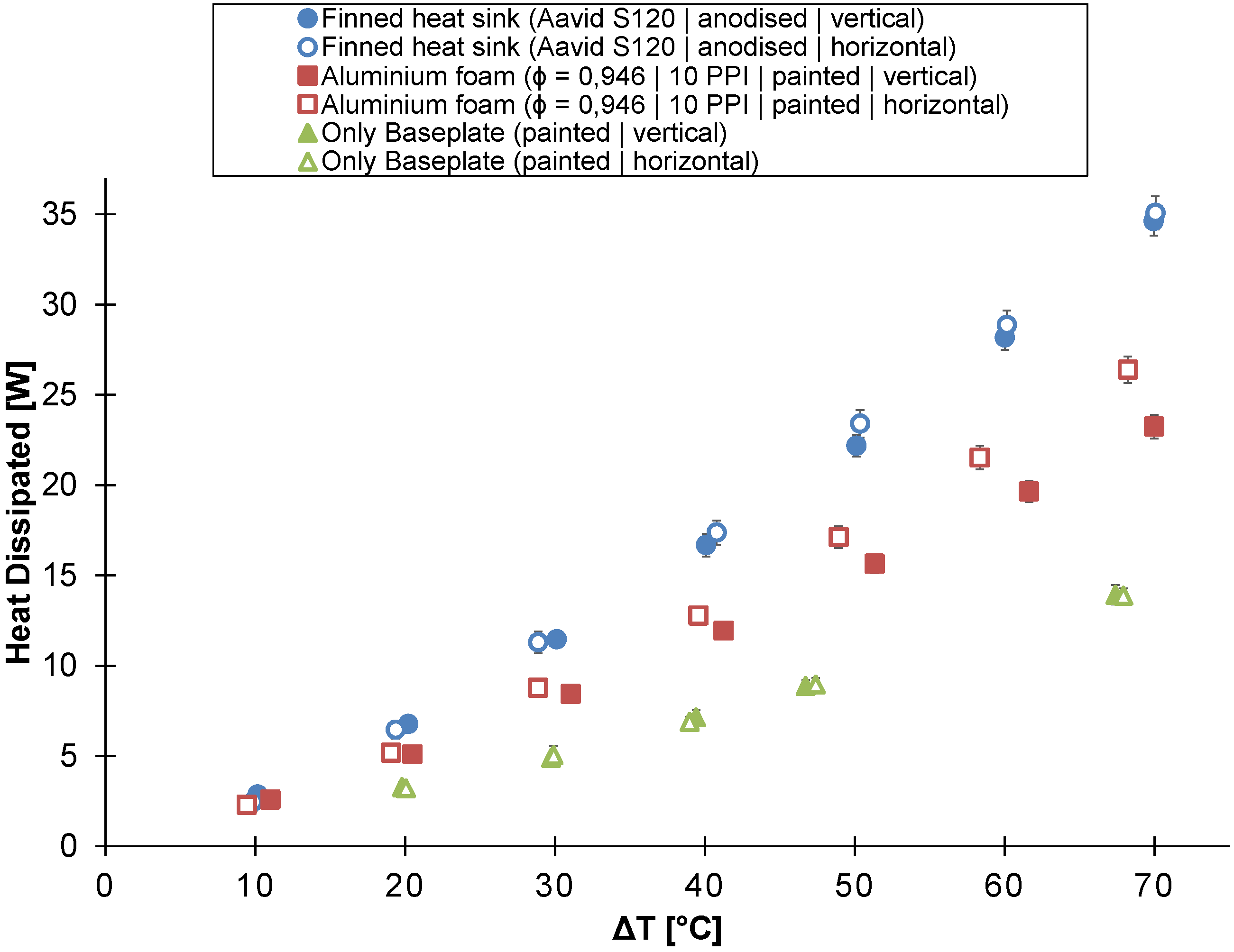
To test the influence of thermal radiation on the total heat transfer in buoyancy-induced convection, an untreated and painted/anodized version of each heat sink was tested. Both painting and anodizing increase the emissivity of the heat sink and, consequently, the heat transfer by thermal radiation. The emissivity of the in-house-made aluminum foam was experimentally determined for both the unpainted and painted version using a thermal emissivity measuring instrument (INGLAS® TIR 100-2, Friedrichshafen, Germany). The emissivity of the unpainted and painted in-house-made aluminum foam is, respectively, 0.540 ± 0.005 and 0.894 ± 0.005. The emissivity of the other heat sinks was not tested, but will be of the same order, except for the emissivity of the untreated finned heat sink and the untreated solid aluminum block. The emissivity of those will be much lower than the one of the in-house-made foam, because their surfaces are very smooth. This emissivity lies between 0.05 and 0.25 [33].
Figure 8 compares the thermal performance of the untreated finned heat sink, the 22 mm-high in-house-made aluminum foam heat sink (reticulated22) and the 22 mm-high solid aluminum block to that of their painted/anodized counterparts. By painting or anodizing, the thermal performance improved for each of the tested heat sinks. The aluminum foam heat sink, the finned heat sink and the aluminum block, respectively, dissipated on average 17%, 31% and 44% more heat after they were painted or anodized.
A comparison between the 40 mm-high in-house-made aluminum foam heat sink (reticulated40), the Alveotec® foam heat sink (spheres40) and the 40mm-high solid aluminum block and their painted counterparts is shown in Figure 10. This figure also indicates that the thermal performance of the tested heat sinks in buoyancy-induced convection increases by painting them. The painted version of the 40 mm-high aluminum foam heat sink, the Alveotec® foam heat sink and the 40 mm-high solid aluminum block, respectively, dissipate on average 11%, 21% and 51% more heat than their unpainted versions.
The relative contribution of the thermal radiation decreases with increasing temperature difference, as shown in both Figure 8 and Figure 10. This trend was also found by Sparrow and Vemuri [34] for pin-fin arrays.
Further, the relative contribution of thermal radiation to the total heat transfer decreases with increasing height of the in-house-manufactured aluminum foam heat sink. In contrast, the relative contribution of thermal radiation to the total heat transfer increases with increasing height for the solid aluminum block. According to De Schampheleire et al. [22], the highest aluminum foam has the largest influence by radiation. This conclusion is the opposite of the one found here. The major difference between the experiments of De Schampheleire et al. and the ones of this study are the dimensions of the base plate of the heat sink. The base plate in the study of De Schampheleire et al. [22] is 254 mm by 25.4 mm, whereas in this study, it is 150 mm by 101 mm. The different ratio between the surface area with a large view factor towards the environment and the total surface area could cause the difference in conclusions.
The improvement by painting/anodizing of the finned heat sink is larger compared to the one of the 22 mm-high in-house-manufactured aluminum foam heat sink (Figure 8). To explain this difference in improvement, the Stefan–Boltzmann law is used, which is defined as:
Q ˙ rad = A F ϵ σ b T h s 4 - T a m b 4
Equation (3) calculates the radiative heat transfer towards the environment ( Q ˙ rad ) given the total outer surface area of the subject (A), the view factor (F), the emissivity (ϵ) and the Stefan–Boltzmann constant ( σ b ).
The larger improvement by the finned heat sink can partly be explained by its larger increase in emissivity by painting. The increase in emissivity for the finned heat sink is almost twice as large as the one of the aluminum foam. According to Equation (3), the increase of thermal radiation should be higher for the finned heat sink.
Moreover, in the case of the aluminum foam heat sink, the absolute increase in dissipated heat by painting flattens with increasing temperature difference. This is not expected according to the Stefan–Boltzmann law (Equation (3)). This flattening is caused by the lower thermal conductivity of the metal foam itself. The average object’s wall temperature, which is an important variable in Equation (3), strongly depends on the thermal conductivity of the heat sink itself. The total heat dissipated by the heat sink increases with increasing temperature difference. This larger heat flux through the heat sink combined with a low thermal conductivity results in a large temperature gradient over the heat sink. This temperature gradient will lower the object’s wall temperature and, therefore, the radiative heat transfer. Because of the fourth power in Equation (3), the effect of the wall temperature is more pronounced than for convective heat transfer, reducing the relative contribution of radiative heat transfer to the total heat transfer in buoyancy-induced convection.

3.4. Orientation

Figure 11 represents the thermal performance of a flat plate (bare base plate), a finned heat sink (Aavid® S120) and the in-house-made aluminum foam heat sink, all having the same outer dimensions and all being painted/anodized, in two different orientations: horizontal and vertical. In the vertical orientation, the four-inch side is aligned with gravity.
The aluminum foam heat sink dissipates almost twice as much heat compared to the flat plate at a temperature difference of 70 C. The heat dissipated by the finned heat sink is about three times more than by the flat plate at a temperature difference of 70 C. For both the flat plate and the finned heat sink, no significant difference in thermal performance can be found between the horizontal and vertical orientation. Nonetheless, the thermal performance of the in-house-made aluminum foam heat sink in the horizontal orientation is up to 18% higher than in the vertical orientation for a temperature difference larger than 30 C.
Figure 11. The heat dissipated by the heat sink at different orientations as a function of the temperature difference between the ambient air and the heat sink’s base plate (heat sink’s height = 22 mm; the 4″-side is parallel with the gravity in the vertical orientation).
Materials 08 05340 g011
The results obtained in this study are different from those found in the literature [19,20]. Both Qu et al. [20] and Bhattacharya et al. [19] did not find any significant difference between the horizontal and vertical orientation. When this study is compared to the ones of Qu et al. [20] and Bhattacharya et al. [19], it is noted that the temperature test range, foam porosity and pore size are very similar. Yet, the foam used by Qu et al. [20] is made of copper instead of aluminum. Further, the experimental setups and the dimensions of the metal foam heat sinks are different for all three studies. Assuming that the experiments found in the literature are conducted correctly, the only difference that can explain the difference in results is the dimensions of the metal foam heat sink. In contrast to the heat sinks tested in this study, which have a rectangular base plate, the heat sinks tested by Qu et al. [20] have a square base plate of 100 mm by 100 mm. Furthermore, the height of the heat sinks tested by Qu et al. [20] is 55 mm, which is more than double the heat sink’s height in this study. No dimensions are specified in the paper of Bhattacharya et al. [19].
Figure 9 and Figure 12 shows that in both horizontal and vertical orientations, the metal foam is penetrated very shallowly by the air flow. This means that in the horizontal orientation, only the regions near the four sides of the foam have a large contribution to the convective heat transfer. Hence, having a rectangular base plate is probably beneficial due to the larger perimeter of the base plate for a given foam volume.
Figure 12. Visualization of the air flow through the in-house-made aluminum foam heat sink (reticulated22) using smoke ( Δ T = 70 C, vertical orientation).
Materials 08 05340 g012

4. Conclusions

In this study, the thermal performance of seven different aluminum heat sinks in buoyancy-induced convection was tested. All heat sinks had the same base plate dimensions (6″× 4″). During the experiments, the temperature difference between the ambient air and the heat sink’s base plate was varied from 10 C to 70 C in steps of 10 C. At each temperature difference, the power dissipated by the heat sink was measured. Based on these experiments, the following conclusions can be made:
At temperature differences higher than 30 C, significant differences in thermal performance exist between the finned and metal foam heat sinks at the tested conditions. The finned heat sink dissipates on average 17% more heat than the 22 mm-high in-house-manufactured aluminum foam heat sink. The Alveotec® foam heat sink dissipates 12% more heat than the 40 mm-high in-house-made foam heat sink.
By increasing the emissivity of a heat sink, the power dissipated by a heat sink in buoyancy-induced convection can be significantly increased by up to 50%. The relative attribution of radiative heat transfer to the total heat transfer decreases for all heat sinks with an increasing temperature difference.
For the tested conditions, metal foam heat sinks dissipate up to 18% more heat in the horizontal orientation.

Acknowledgments

Research funded by a Ph.D. grant (No. 141733) of the Agency for Innovation by Science and Technology (IWT).

Author Contributions

Marijn Billiet, Sven De Schampheleire and Henk Huisseune conceived and designed the experiments. Marijn Billiet performed the experiments and analyzed the data. Marijn Billiet, Sven De Schampheleire and Henk Huisseune wrote the paper. Michel De Paepe supervised the study.

Conflicts of Interest

The authors declare no conflict of interest.

References

  1. Burris, M. Component Failures: How They Fail and How to Identify Failed Components. Available online: http://components.about.com/od/Components/a/Component-Failures.htm (accessed on 30 July 2015).
  2. U.S. Department of Energy. Building Technologies Program: Solid-State Lighting Technology Fact Sheet. Available online: http://www.webcitation.org/6aKbWerxo (accessed on 30 July 2015).
  3. Meyaard, D.S.; Shan, Q.; Cho, J.; Fred Schubert, E.; Han, S.H.; Kim, M.H.; Sone, C.; Jae Oh, S.; Kyu Kim, J. Temperature dependent efficiency droop in GaInN light-emitting diodes with different current densities. Appl. Phys. Lett. 2012, 100. [Google Scholar] [CrossRef]
  4. CREE®; CREE Inc., Durham, NC, USA. Thermal Management of Cree® XLamp® LEDs. Available online: http://www.webcitation.org/6aKchRqUw (accessed on 30 July 2015).
  5. Kolar, J.; Drofenik, U.; Biela, J.; Heldwein, M.; Ertl, H.; Friedli, T.; Round, S. PWM Converter Power Density Barriers. In Proceedings of the Power Conversion Conference (PCC), Nagoya, Japan, 2–5 April 2007; pp. 9–29.
  6. Pop, E. Energy dissipation and transport in nanoscale devices. Nano Res. 2010, 3, 147–169. [Google Scholar] [CrossRef]
  7. Calamas, D.; Baker, J. Behavior of Thermally Radiating Tree-like Fins. Heat Transfer 2013, 135. [Google Scholar] [CrossRef]
  8. Dogan, M.; Sivrioglu, M.; Yılmaz, O. Numerical analysis of natural convection and radiation heat transfer from various shaped thin fin-arrays placed on a horizontal plate-a conjugate analysis. Energy Convers. Manage. 2014, 77, 78–88. [Google Scholar] [CrossRef]
  9. Bornoff, R.; Parry, J. An additive design heat sink geometry topology identification and optimisation algorithm. In Proceedings of the 31st Thermal Measurement, Modeling Management Symposium (SEMI-THERM), San Jose, CA, USA, 15–19 March 2015; pp. 303–308.
  10. De Jaeger, P.; T’Joen, C.; Huisseune, H.; Ameel, B.; de Paepe, M. An experimentally validated and parameterized periodic unit-cell reconstruction of open-cell foams. J. Appl. Phys. 2011, 109. [Google Scholar] [CrossRef]
  11. Ashby, F. Metal Foams: A Design Guide; Chemical Petrochemical & Process; Butterworth-Heinemann: Oxford, UK, 2000. [Google Scholar]
  12. Banhart, J. Manufacture, characterisation and application of cellular metals and metal foams. Prog. Mater Sci. 2001, 46, 559–632. [Google Scholar] [CrossRef]
  13. Dukhan, N. Metal Foams: Fundamentals and Applications; Destech Publications: Lancaster, PA, USA, 2013. [Google Scholar]
  14. Volz, R. Reticulated Polyurethane Foams and Process for Their Production. U.S. Patent 3,171,820, 2 March 1965. [Google Scholar]
  15. Jinnapat, A.; Kennedy, A. The Manufacture and Characterisation of Aluminum Foams Made by Investment Casting Using Dissolvable Spherical Sodium Chloride Bead Preforms. Metals 2011, 1. [Google Scholar] [CrossRef]
  16. Zhao, C. Review on thermal transport in high porosity cellular metal foams with open cells. Int. J. Heat Mass Transfer 2012, 55, 3618–3632. [Google Scholar] [CrossRef]
  17. Mancin, S.; Zilio, C.; Diani, A.; Rossetto, L. Air forced convection through metal foams: Experimental results and modeling. Int. J. Heat Mass Transfer 2013, 62, 112–123. [Google Scholar] [CrossRef]
  18. De Schampheleire, S.; de Jaeger, P.; Huisseune, H.; Ameel, B.; T’Joen, C.; de Kerpel, K.; de Paepe, M. Thermal hydraulic performance of 10 PPI aluminum foam as alternative for louvered fins in an HVAC heat exchanger. Appl. Therm. Eng. 2013, 51, 371–382. [Google Scholar] [CrossRef]
  19. Bhattacharya, A.; Mahajan, R.L. Metal Foam and Finned Metal Foam Heat Sinks for Electronics Cooling in Buoyancy-Induced Convection. J. Electron. Packag. 2005, 128, 259–266. [Google Scholar] [CrossRef]
  20. Qu, Z.; Wang, T.; Tao, W.; Lu, T. Experimental study of air natural convection on metallic foam-sintered plate. Int. J. Heat Fluid Flow 2012, 38, 126–132. [Google Scholar] [CrossRef]
  21. De Schampheleire, S.; de Jaeger, P.; Reynders, R.; de Kerpel, K.; Ameel, B.; T’Joen, C.; Huisseune, H.; Lecompte, S.; de Paepe, M. Experimental study of buoyancy-driven flow in open-cell aluminum foam heat sinks. Appl. Therm. Eng. 2013, 59, 30–40. [Google Scholar] [CrossRef]
  22. De Schampheleire, S.; de Kerpel, K.; de Jaeger, P.; Huisseune, H.; Ameel, B.; de Paepe, M. Buoyancy driven convection in open-cell metal foam using the volume averaging theory. Appl. Therm. Eng. 2015, 79, 225–233. [Google Scholar] [CrossRef]
  23. Sikka, K.; Torrance, K.; Scholler, C.; Salanova, P. Heat sinks with fluted and wavy plate fins in natural and low-velocity forced convection. IEEE Trans. Compon. Packag. Technol. 2002, 25, 283–292. [Google Scholar] [CrossRef]
  24. Khor, Y.K.; Hung, Y.M.; Lim, B.K. On the role of radiation view factor in thermal performance of straight-fin heat sinks. Int. Commun. Heat Mass Transfer 2010, 37, 1087–1095. [Google Scholar] [CrossRef]
  25. Alvéotec; Venissieux, France. Innovation Fonderie. Available online: http://www.alveotec.fr/en/our-news/unique-aluminum-foam-from-goodfellow_41.html (accessed on 24 March 2015).
  26. Brun, E. De L’Imagerie 3D des Structures a L’Etude des Mecanismes de Transport en Milieux Cellulaires; Institut Universitaire des Systèmes Thermiques Industriels, Aix-Marseille Université: Marseille, France, 2009. [Google Scholar]
  27. Aavid Thermalloy (Laconia, NH, USA). Available online: http://www.aavid.com/ (accessed on 24 March 2015).
  28. Taylor, J. An Introduction to Error Analysis: The Study of Uncertainties in Physical Measurements; University Science Books: Dulles, VI, USA, 1997. [Google Scholar]
  29. Churchill, S.W.; Chu, H.H. Correlating equations for laminar and turbulent free convection from a vertical plate. Int. J. Heat Mass Transfer 1975, 18, 1323–1329. [Google Scholar] [CrossRef]
  30. Nellis, G.; Klein, S. Heat Transfer; Cambridge University Press: Cambridge, UK, 2012. [Google Scholar]
  31. Taji, S.; Parishwad, G.; Sane, N. Experimental investigation of heat transfer and flow pattern from heated horizontal rectangular fin array under natural convection. Heat Mass Transfer 2014, 50, 1005–1015. [Google Scholar] [CrossRef]
  32. De Jaeger, P.; T’Joen, C.; Huisseune, H.; Ameel, B.; de Schampheleire, S.; de Paepe, M. Assessing the influence of four bonding methods on the thermal contact resistance of open-cell aluminum foam. Int. J. Heat Mass Transfer 2012, 55, 6200–6210. [Google Scholar] [CrossRef]
  33. Fluke®; Everett, WA, USA. Emissivity values of common materials. Available online: http://www.webcitation.org/6aKc191IN (accessed on 30 July 2015).
  34. Sparrow, E.; Vemuri, S. Orientation effects on natural convection/radiation heat transfer from pin-fin arrays. Int. J. Heat Mass Transfer 1986, 29, 359–368. [Google Scholar] [CrossRef]

