Applications of Piezoelectric Materials in Structural Health Monitoring and Repair: Selected Research Examples

Abstract
:1. Introduction
2. Piezoelectric Materials and Applications
3 Analysis and Applications of Piezoelectric Sensors and Actuators
3.1. Plain Piezoelectric Sensors and Actuators
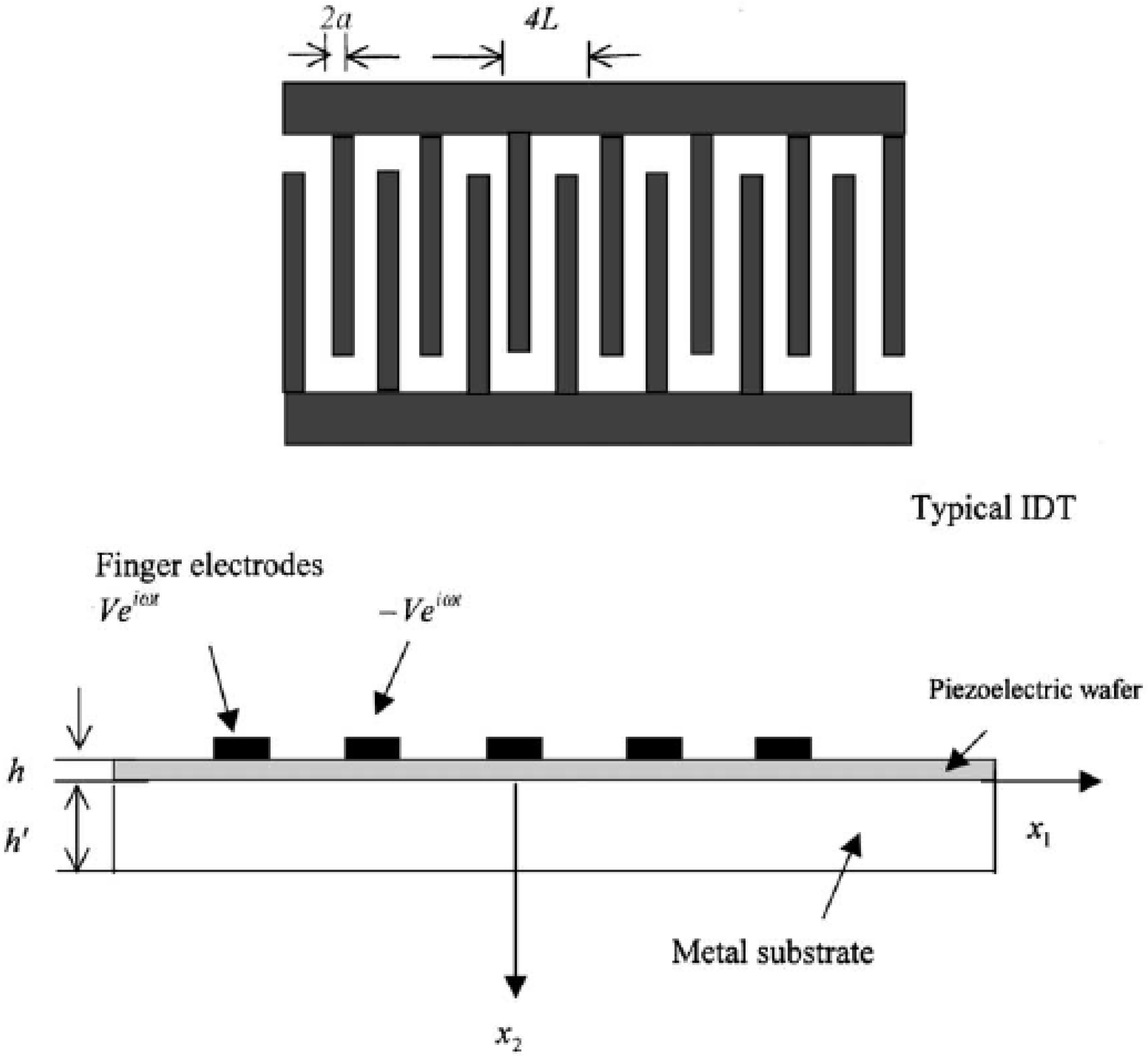
3.2. Interdigital Transducer
4. Structural Health Monitoring
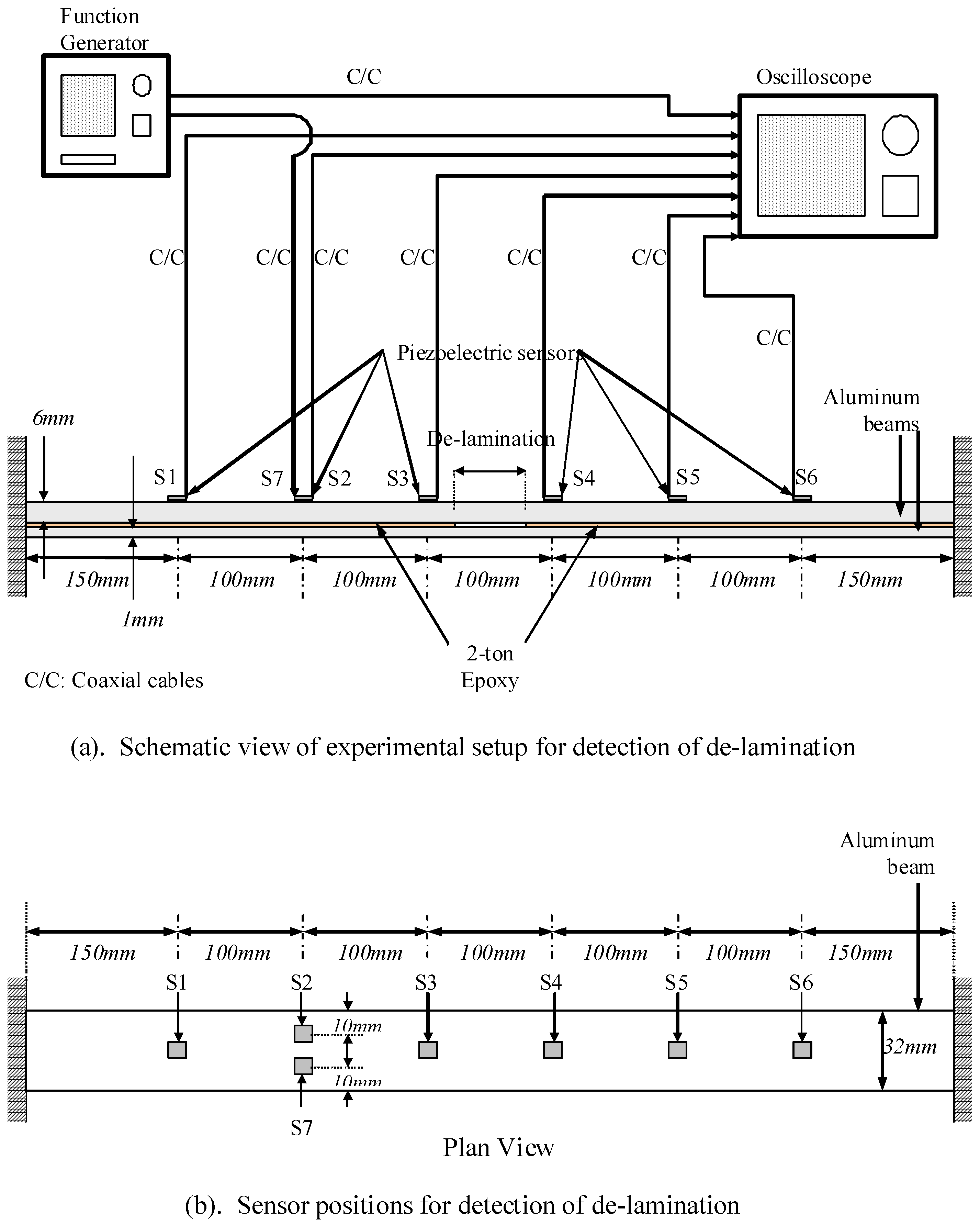
4.1. Beams


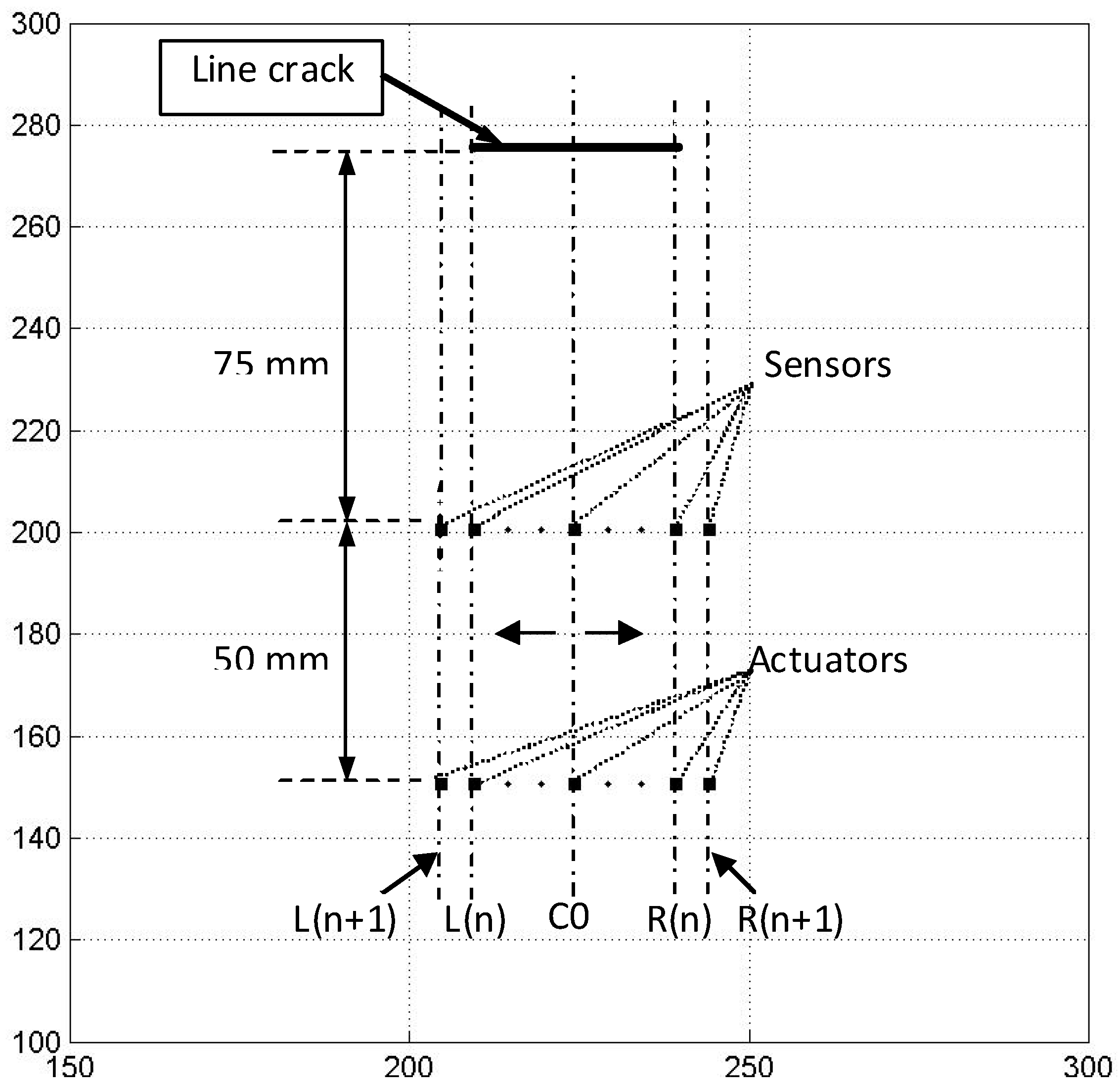
4.2. Plates


4.3. Pipes
5. Repair of Structures with Smart Materials
5.1. Beams

5.2. Plates


6. Conclusions
Acknowledgements
References and Notes
- Bourasseau, N.; Moulin, E.; Delebarre, C.; Bonniau, P. Radome health monitoring with Lamb waves: experimental approach. NDT E Int. 2000, 33, 393–400. [Google Scholar] [CrossRef]
- Ghosh, T.; Kundu, T.; Karpur, P. Efficient use of Lamb modes for detecting defects in large plates. Ultrasonics 1998, 36, 791–801. [Google Scholar] [CrossRef]
- Tan, K.S.; Guo, N.; Wong, B.S.; Tui, C.G. Comparison of Lamb waves and pulse echo in detection of near-surface defects in laminate plates. NDT E Int. 1995, 28, 215–223. [Google Scholar] [CrossRef]
- Salawu, O.S. Detection of structural damage through changes in frequency: A review. Eng. Struct. 1997, 19, 718–723. [Google Scholar] [CrossRef]
- Quek, S.T.; Wang, Q.; Zhang, L.; Ong, K.H. Practical issues in the detection of damage in beams using wavelets. Smart Mater. Struct. 2001, 10, 1009–1017. [Google Scholar] [CrossRef]
- Quek, S.T.; Wang, Q. On dispersion relations in piezoelectric coupled-plate structures. Smart Mater. Struct. 2000, 9, 859–867. [Google Scholar] [CrossRef]
- Wang, Q.; Quek, S.T. Dispersion relations in piezoelectric coupled beams. AIAA J. 2000, 38, 2357–2361. [Google Scholar] [CrossRef]
- Wang, Q.; Quek, S.T. Flexural vibration analysis of sandwich beam coupled with piezoelectric actuator. Smart Mater. Struct. 2000, 9, 103–109. [Google Scholar] [CrossRef]
- Quek, S.T.; Wang, Q.; Zhang, L.; Ang, K.K. Sensitivity analysis of crack detection in beams by wavelet technique. Int. J. Mech. Sci. 2001, 43, 2899–2910. [Google Scholar] [CrossRef]
- Wang, Q.; Quek, S.T.; Sun, C.T.; Liu, X. Analysis of piezoelectric coupled circular plate. Smart Mater. Struct. 2001, 10, 229–239. [Google Scholar] [CrossRef]
- Wang, Q.; Quek, S.T.; Varadan, V.K. Love waves in piezoelectric coupled solid media. Smart Mater. Struct. 2001, 10, 380–388. [Google Scholar] [CrossRef]
- Jin, J.; Wang, Q.; Quek, S.T. Lamb wave propagation in a metallic semi-infinite medium covered with piezoelectric layer. Int. J. Solids Struct. 2002, 39, 2547–2556. [Google Scholar] [CrossRef]
- Wang, Q.; Jin, J.; Quek, S.T. Propagation of a shear direction acoustic wave in piezoelectric coupled cylinders. J. Appl. Mech. 2002, 69, 391–394. [Google Scholar] [CrossRef]
- Wang, Q.; Varadan, V.K. Wave propagation in piezoelectric coupled plates by use of interdigital transducer Part 1. Dispersion characteristics. Int. J. Solids Struct. 2002, 39, 1119–1130. [Google Scholar] [CrossRef]
- Wang, Q.; Varadan, V.K. Wave propagation in piezoelectric coupled plates by use of interdigital transducer. Part 2: Wave excitation by interdigital transducer. Int. J. Solids Struct. 2002, 39, 1131–1144. [Google Scholar] [CrossRef]
- Wang, Q.; Varadan, V.K. Longitudinal wave propagation in piezoelectric coupled rods. Smart Mater. Struct. 2002, 11, 48–54. [Google Scholar] [CrossRef]
- Jin, J.; Quek, S.T.; Wang, Q. Analytical solution of excitation of Lamb waves in plates by inter-digital transducers. P Roy. Soc. A-Math. Phy. 2003, 459, 1117–1134. [Google Scholar] [CrossRef]
- Quek, S.T.; Tua, P.S.; Wang, Q. Detecting anomalies in beams and plate based on the Hilbert-Huang transform of real signals. Smart Mater. Struct. 2003, 12, 447–460. [Google Scholar] [CrossRef]
- Quek, S.T.; Jin, J.; Tua, P.S. Comparison of plain piezoceramics and inter-digital transducer for crack detection in plates. In Proceedings of Smart Structures and Materials 2004: Smart Structures and Integrated Systems, San Diego, CA, USA, 2004; Flatau, A.B., Ed.; pp. 542–551.
- Tua, P.S.; Quek, S.T.; Wang, Q. Detection of cracks in plates using piezo-actuated Lamb waves. Smart Mater. Struct. 2004, 13, 643–660. [Google Scholar] [CrossRef]
- Jin, J.; Quek, S.T.; Wang, Q. Wave boundary element to study Lamb wave propagation in plates. J. Sound Vibr. 2005, 288, 195–213. [Google Scholar] [CrossRef]
- Jin, J.; Quek, S.T.; Wang, Q. Design of interdigital transducers for crack detection in plates. Ultrasonics 2005, 43, 481–493. [Google Scholar] [CrossRef] [PubMed]
- Tua, P.S.; Quek, S.T.; Wang, Q. Detection of cracks in cylindrical pipes and plates using piezo-actuated Lamb waves. Smart Mater. Struct. 2005, 14, 1325–1342. [Google Scholar] [CrossRef]
- Tua, P.S.; Quek, S.T.; Wang, Q. Detection of crack in thin cylindrical pipes using piezo-actuated lamb waves. In Proceedings Smart Structures and Materials 2005: Sensors and Smart Structures Technologies for Civil, Mechanical, and Aerospace, Pts 1 and 2. San Diego, CA, USA, 2005; Tomizuka, M., Ed.;
- Wang, Q.; Quek, S.T.; Varadan, V.K. Analytical solution for shear horizontal wave propagation in piezoelectric coupled media by interdigital transducer. J. Appl. Mech.-Trans. ASME 2005, 72, 341–350. [Google Scholar] [CrossRef]
- Quek, S.T.; Tua, P.S.; Jin, J. Comparison of plain piezoceramics and inter-digital transducer for crack detection in plates. J. Intel. Mat. Syst. Str. 2007, 18, 949–961. [Google Scholar] [CrossRef]
- Zou, Y.; Tong, L.; Steven, G.P. Vibration-based model-dependent damage (delamination) identification and health monitoring for composite structures - A review. J. Sound Vib. 2000, 230, 357–378. [Google Scholar] [CrossRef]
- Tay, T.E.; Tan, V.B.C.; Deng, M. Element-failure concepts for dynamic fracture and delamination in low-velocity impact of composites. Int. J. Solids Struct. 2003, 40, 555–571. [Google Scholar] [CrossRef]
- Kitamura, T.; Hirakata, H.; Itsuji, T. Effect of residual stress on delamination from interface edge between nano-films. Eng. Fract. Mech. 2003, 70, 2089–2101. [Google Scholar] [CrossRef]
- Turon, A.; Camanho, P.P.; Costa, J.; Davila, C.G. A damage model for the simulation of delamination in advanced composites under variable-mode loading. Mech. Mater. 2006, 38, 1072–1089. [Google Scholar] [CrossRef]
- Li, S.; Wang, J.; Thouless, M.D. The effects of shear on delamination in layered materials. J. Mech. Phys. Solids 2004, 52, 193–214. [Google Scholar] [CrossRef]
- Todoroki, A.; Ueda, M. Low-cost delamination monitoring of CFRP beams using electrical resistance changes with neural networks. Smart Mater. Struct. 2006, 15, N75–N84. [Google Scholar] [CrossRef]
- Baker, A.A.; Rose, L.R.F.; Jones, R. Advances in The Bonded Composite Repair of Metallic Aircraft Structure, 1st ed.; Elsevier: Amsterdam, the Netherlands, 2002. [Google Scholar]
- Sohn, H.; Park, G.; Wait, J.R.; Limback, N.P.; Farrar, C.R. Wavelet-based active sensing for delamination detection in composite structures. Smart Mater. Struct. 2004, 13, 153–160. [Google Scholar] [CrossRef]
- Ip, K.H.; Mai, Y.W. Delamination detection in smart composite beams using Lamb waves. Smart Mater. Struct. 2004, 13, 544–551. [Google Scholar] [CrossRef]
- Chrysochoidis, N.A.; Saravanos, D.A. Assessing the effects of delamination on the damped dynamic response of composite beams with piezoelectric actuators and sensors. Smart Mater. Struct. 2004, 13, 733–742. [Google Scholar] [CrossRef]
- Webster, J.G. The measurement, instrumentation, and sensors handbook; (The electrical engineering handbook series); CRC Press and IEEE Press: Boca Raton, Fl, USA, 1999. [Google Scholar]
- Gururaja, T.R. Piezoelectrics for medical ultrasonic-imaging. Am. Ceram. Soc. Bull. 1994, 73, 50–55. [Google Scholar]
- Liang, C.; Sun, F.P.; Rogers, C.A. Coupled electromechanical analysis of adaptive material systems - determination of the actuator power-consumption and system energy-transfer. J. Intel. Mat. Syst. Str. 1994, 5, 12–20. [Google Scholar] [CrossRef]
- Giurgiutiu, V.; Reynolds, A.; Rogers, C.A. Experimental investigation of E/M impedance health monitoring for spot-welded structural joints. J. Intel. Mat. Syst. Str. 1999, 10, 802–812. [Google Scholar] [CrossRef]
- Giurgiutiu, V.; Zagrai, A.N. Characterization of piezoelectric wafer active sensors. J. Intel. Mat. Syst. Str. 2000, 11, 959–976. [Google Scholar] [CrossRef]
- Zagrai, A.N.; Giurgiutiu, V. Electro-mechanical impedance method for crack detection in thin plates. J. Intel. Mat. Syst. Str. 2001, 12, 709–718. [Google Scholar] [CrossRef]
- Giurgiutiu, V.; Zagrai, A.N. Embedded self-sensing piezoelectric active sensors for on-line structural identification. J. Vib. Acoust.-Trans. ASME 2002, 124, 116–125. [Google Scholar] [CrossRef]
- Duan, W.H.; Quek, S.T.; Wang, Q. A novel ring type ultrasonic motor with multiple wavenumbers: design, fabrication and characterization. Smart Mater. Struct. 2009, 18, 125025. [Google Scholar] [CrossRef]
- Duan, W.H.; Quek, S.T.; Lim, S.P. Finite element solution for intermittent-contact problem with piezoelectric actuation in ring type USM. Finite Elem. Anal. Des. 2007, 43, 193–205. [Google Scholar] [CrossRef]
- Wang, S.Y.; Tai, K.; Quek, S.T. Topology optimization of piezoelectric sensors/actuators for torsional vibration control of composite plates. Smart Mater. Struct. 2006, 15, 253–269. [Google Scholar] [CrossRef]
- Wang, S.Y.; Quek, S.T.; Ang, K.K. Dynamic stability analysis of finite element modeling of piezoelectric composite plates. Int. J. Solids Struct. 2004, 41, 745–764. [Google Scholar] [CrossRef]
- Wang, S.Y.; Quek, S.T.; Ang, K.K. Vibration control of smart piezoelectric composite plates. Smart Mater. Struct. 2001, 10, 637–644. [Google Scholar] [CrossRef]
- Wang, S.Y.; Quek, S.T.; Ang, K.K. LQR vibration control of piezoelectric composite plates. In Proceedings of Smart Structures and Devices, San Diego, CA, USA, 2001; Sood, D.K., Lawes, R.A., Varadan, V.V., Eds.; pp. 375–386.
- Wang, Q.; Quek, S.T. Enhancing flutter and buckling capacity of column by piezoelectric layers. Int. J. Solids Struct. 2002, 39, 4167–4180. [Google Scholar] [CrossRef]
- Wang, Q.; Quek, S.T.; Liew, K.M. On the repair of a cracked beam with a piezoelectric patch. Smart Mater. Struct. 2002, 11, 404–410. [Google Scholar]
- Wang, Q.; Duan, W.H.; Quek, S.T. Repair of notched beam under dynamic load using piezoelectric patch. Int. J. Mech. Sci. 2004, 46, 1517–1533. [Google Scholar] [CrossRef]
- Wang, Q.; Quek, S.T. Repair of delaminated beams via piezoelectric patches. Smart Mater. Struct. 2004, 13, 1222–1229. [Google Scholar] [CrossRef]
- Wang, Q.; Quek, S.T. Repair of cracked column under axially compressive load via piezoelectric patch. Comput. Struct. 2005, 83, 1355–1363. [Google Scholar] [CrossRef]
- Wang, Q.; Zhou, G.Y.; Quek, S.T. Repair of delaminated beams subjected to compressive force via piezoelectric layers. Adv. Struct. Eng. 2005, 8, 411–425. [Google Scholar] [CrossRef]
- Duan, W.H.; Quek, S.T.; Wang, Q. Finite element analysis of the piezoelectric-based repair of a delaminated beam. Smart Mater. Struct. 2008, 17, 015017. [Google Scholar] [CrossRef]
- Wu, N.; Wang, Q. Repair of vibrating delaminated beam structures using piezoelectric patches. Smart Mater. Struct. 2010, 19. [Google Scholar]
- Wu, N.; Wang, Q. Repair of a delaminated plate under static loading with piezoelectric patches. Smart Mater. Struct. 2010, 19, 105025. [Google Scholar] [CrossRef]
- Rabinovitch, O. Piezoelectric control of edge debonding in beams strengthened with composite materials: Part II - Failure criteria and optimization. J. Compos Mater. 2007, 41, 657–677. [Google Scholar] [CrossRef]
- Rabinovitch, O. Piezoelectric control of edge debonding in beams strengthened with composite materials: Part I - Analytical modeling. J. Compos Mater. 2007, 41, 525–546. [Google Scholar] [CrossRef]
- Ariaei, A.; Ziaei-Rad, S.; Ghayour, M. Repair of a cracked Timoshenko beam subjected to a moving mass using piezoelectric patches. Int. J. Mech. Sci. 2010, 52, 1074–1091. [Google Scholar] [CrossRef]
- Liu, T.J.C. Crack repair performance of piezoelectric actuator estimated by slope continuity and fracture mechanics. Eng. Fract. Mech. 2008, 75, 2566–2574. [Google Scholar] [CrossRef]
- Alaimo, A.; Milazzo, A.; Orlando, C. Boundary elements analysis of adhesively bonded piezoelectric active repair. Eng. Fract. Mech. 2009, 76, 500–511. [Google Scholar] [CrossRef]
- Song, G.; Mo, Y.L.; Otero, K.; Gu, H. Health monitoring and rehabilitation of a concrete structure using intelligent materials. Smart Mater. Struct. 2006, 15, 309–314. [Google Scholar] [CrossRef]
- Pohl, J.; Herold, S.; Mook, G.; Michel, F. Damage detection in smart CFRP composites using impedance spectroscopy. Smart Mater. Struct. 2001, 10, 834–842. [Google Scholar] [CrossRef]
- Cheng, J.Q.; Taheri, F. A smart single-lap adhesive joint integrated with partially distributed piezoelectric patches. Int. J. Solids Struct. 2006, 43, 1079–1092. [Google Scholar] [CrossRef]
- Crawley, E.F.; Deluis, J. Use of piezoelectric actuators as elements of intelligent structures. AIAA J. 1987, 25, 1373–1385. [Google Scholar] [CrossRef]
- Lee, C.K.; Moon, F.C. Laminated piezopolymer plates for torsion and bending sensors and actuators. J. Acoust. Soc. Am. 1989, 85, 2432–2439. [Google Scholar] [CrossRef]
- Curtis, R.G.; Redwood, M. Transverse surface waves on a piezoelectric material carrying a metal layer of finite thickness. J. Appl. Phys. 1973, 44, 2002–2007. [Google Scholar] [CrossRef]
- Cheng, N.C.; Sun, C.T. Wave propagation in two - layered piezoelectric plates. J. Acoust. Soc. Am. 1975, 57, 632–638. [Google Scholar] [CrossRef]
- Sun, C.T.; Cheng, N.C. Piezoelectric waves on a layered cylinder. J. Appl. Phys. 1974, 45, 4288–4294. [Google Scholar] [CrossRef]
- Wang, S.Y.; Quek, S.T.; Ang, K.K. Optimal placement of piezoelectric sensor/actuator pairs for vibration control of composite plates. In Proceedings of Smart Structures and Materials 2002: Modeling, Signal Processing, and Control, San Diego, CA, USA, 2002; Rao, V.S., Ed.; pp. 461–471.
- Wang, Q.; Wang, C.M. A controllability index for optimal design of piezoelectric actuators in vibration control of beam structures. J. Sound Vibr. 2001, 242, 507–518. [Google Scholar] [CrossRef]
- Wang, Q.; Quek, S.T. A model for the analysis of beams with embedded piezoelectric layers. J. Intel. Mat. Syst. Str. 2002, 13, 61–70. [Google Scholar] [CrossRef]
- Liu, X.; Wang, Q.; Quek, S.T. Analytical solution for free vibration of piezoelectric coupled moderately thick circular plates. Int. J. Solids Struct. 2002, 39, 2129–2151. [Google Scholar] [CrossRef]
- Wang, Q.A. SH wave propagation in piezoelectric coupled plates. IEEE Trans. Ultrason. Ferroelectr. Freq. Control 2002, 49, 596–603. [Google Scholar] [CrossRef] [PubMed]
- Duan, W.H.; Quek, S.T.; Wang, Q. Free vibration analysis of piezoelectric coupled thin and thick annular plate. J. Sound Vibr. 2005, 281, 119–139. [Google Scholar] [CrossRef]
- Wang, Q.; Liew, K.M. Analysis of wave propagation in piezoelectric coupled cylinder affected by transverse shear and rotary inertia. Int. J. Solids Struct. 2003, 40, 6653–6667. [Google Scholar] [CrossRef]
- Wang, Q. Axi-symmetric wave propagation in a cylinder coated with a piezoelectric layer. Int. J. Solids Struct. 2002, 39, 3023–3037. [Google Scholar] [CrossRef]
- Wang, Q. Wave propagation in a piezoelectric coupled cylindrical membrane shell. Int. J. Solids Struct. 2001, 38, 8207–8218. [Google Scholar] [CrossRef]
- Tzou, H.S.; Tseng, C.I. Distributed piezoelectric sensor actuator design for dynamic measurement control of distributed parameter-systems - a piezoelectric finite-element approach. J. Sound Vibr. 1990, 138, 17–34. [Google Scholar] [CrossRef]
- Ha, S.K.; Keilers, C.; Chang, F.K. Finite-element analysis of composite structures containing distributed piezoceramic sensors and actuators. AIAA J. 1992, 30, 772–780. [Google Scholar] [CrossRef]
- Hwang, W.S.; Park, H.C. Finite-element modeling of piezoelectric sensors and actuators. AIAA J. 1993, 31, 930–937. [Google Scholar] [CrossRef]
- Lam, K.Y.; Peng, X.Q.; Liu, G.R.; Reddy, J.N. A finite-element model for piezoelectric composite laminates. Smart Mater. Struct. 1997, 6, 583–591. [Google Scholar] [CrossRef]
- Bent, A.A.; Hagood, N.W.; Rodgers, J.P. anisotropic actuation with piezoelectric fiber composites. J. Intel. Mat. Syst. Str. 1995, 6, 338–349. [Google Scholar] [CrossRef]
- Bent, A.A.; Hagood, N.W. Piezoelectric fiber composites with interdigitated electrodes. J. Intel. Mat. Syst. Str. 1997, 8, 903–919. [Google Scholar] [CrossRef]
- Varadan, V.K.; Varadan, V.V. Microsensors, microelectromechanical systems (MEMS), and electronics for smart structures and systems. Smart Mater. Struct. 2000, 9, 953. [Google Scholar] [CrossRef]
- Morgan, D.P. History of saw devices. In Proceedings of the 1998 IEEE International Frequency Control Symposium, Pasadena, CA, USA, 1998.
- White, R.M. Acoustic sensors for physical, chemical and biochemical applications. In Proceedings of the 1998 IEEE International Frequency Control Symposium, Pasadena, CA, USA, 1998.
- Auld, B.A. Acoustic Fields and Waves in Solids, 2nd ed.; Krieger Publishing Company: Malabar, FL, USA, 1990. [Google Scholar]
- Parton, V.Z.; Kudriavtsev, B.A.; Senik, N.A. Electromagnetoelasticity; Hemisphere Pub. Corp: New York, NY, USA, 1990. [Google Scholar]
- Curtis, R.G.; Redwood, M. Transverse surface-waves on a piezoelectric material carrying a metal layer of finite thickness. J. Appl. Phys. 1973, 44, 2002–2007. [Google Scholar] [CrossRef]
- Feng, H.H.; Li, X.J. Shear-horizontal surface-waves in a layered structure of piezoelectric ceramics. IEEE Trans. Ultrason. Ferroelectr. Freq. Control 1993, 40, 167–170. [Google Scholar] [CrossRef] [PubMed]
- Feng, H.H.; Li, X.J. Shear-horizontal surface-waves in the layered structure. In Proceedings of IEEE 1991 Ultrasonics Symposium, Lake buena vista, FL, USA, 1991; McAvoy, B.R., Ed.; Volumes 1 and 2, pp. 415–418.
- Kielczynski, P.J.; Pajewski, W.; Szalewski, M. Shear-horizontal surface-waves on piezoelectric ceramics with depolarized surface-layer. IEEE Trans. Ultrason. Ferroelectr. Freq. Control 1989, 36, 287–293. [Google Scholar] [CrossRef] [PubMed]
- Wang, Q. Wave propagation in a piezoelectric coupled solid medium. J. Appl. Mech.-Trans. ASME 2002, 69, 819–824. [Google Scholar] [CrossRef]
- Milsom, R.F.; Reilly, N.H.C.; Redwood, M. Analysis of generation and detection of surface and bulk acoustic-waves by interdigital transducers. IEEE Trans. Sonics Ultrason. 1977, 24, 147–166. [Google Scholar] [CrossRef]
- Tseng, C.C. Frequency response of an interdigital transducer for excitation of surface elastic waves. IEEE Trans. Electron Devices 1968, ED15, 586–594. [Google Scholar] [CrossRef]
- Coquin, G.A.; Tiersten, H.F. Analysis of excitation and detection of piezoelectric surface waves in quartz by means of surface electrodes. J. Acoust. Soc. Am. 1967, 41, 921–939. [Google Scholar] [CrossRef]
- Joshi, S.G.; White, R.M. Excitation and detection of surface elastic waves in piezoelectric crystals. J. Acoust. Soc. Am. 1969, 46, 17–27. [Google Scholar] [CrossRef]
- Hasegawa, K.; Koshiba, M. Finite-element solution of Rayleigh-wave scattering from reflective gratings on a piezoelectric substrate. IEEE Trans. Ultrason. Ferroelectr. Freq. Control 1990, 37, 99–105. [Google Scholar] [CrossRef] [PubMed]
- Xu, G.S. Direct finite-element analysis of the frequency response of a Y-Z lithium niobate SAW filter. Smart Mater. Struct. 2000, 9, 973–980. [Google Scholar] [CrossRef]
- Hashimoto, K. Simulation of surface acoustic wave devices. Jpn. J. Appl. Phys. Part 1 - Regul. Pap. Brief Commun. Rev. Pap. 2006, 45, 4423–4428. [Google Scholar] [CrossRef]
- Cho, Y.H.; Rose, J.L. A boundary element solution for a mode conversion study oil the edge reflection of Lamb waves. J. Acoust. Soc. Am. 1996, 99, 2097–2109. [Google Scholar] [CrossRef]
- Cho, Y.H.; Hongerholt, D.D.; Rose, J.L. Lamb wave scattering analysis for reflector characterization. IEEE Trans. Ultrason. Ferroelectr. Freq. Control 1997, 44, 44–52. [Google Scholar] [CrossRef] [PubMed]
- Zhao, X.L.; Rose, J.L. Boundary element modeling for defect characterization potential in a wave guide. Int. J. Solids Struct. 2003, 40, 2645–2658. [Google Scholar] [CrossRef]
- Balasubramanyam, R.; Quinney, D.; Challis, R.E.; Todd, C.P.D. A finite-difference simulation of ultrasonic Lamb waves in metal sheets with experimental verification. J. Phy. D Appl. Phys. 1996, 29, 147–155. [Google Scholar] [CrossRef]
- Yuan, X.J.; Borup, D.; Wiskin, J.; Berggren, P.; Johnson, S.A. Simulation of acoustic wave propagation in dispersive media with relaxation losses by using FDTD method with PML absorbing boundary condition. IEEE Trans. Ultrason. Ferroelectr. Freq. Control 1999, 46, 14–23. [Google Scholar] [CrossRef] [PubMed]
- Hosokawa, A. Simulation of ultrasound propagation through bovine cancellous bone using elastic and Biot's finite-difference time-domain methods. J. Acoust. Soc. Am. 2005, 118, 1782–1789. [Google Scholar] [CrossRef] [PubMed]
- Fink, M. Time-reversal of ultrasonic fields .1. basic principles. IEEE Trans. Ultrason. Ferroelectr. Freq. Control 1992, 39, 555–566. [Google Scholar] [CrossRef]
- Fink, M.; Cassereau, D.; Derode, A.; Prada, C.; Roux, P.; Tanter, M.; Thomas, J.L.; Wu, F. Time-reversed acoustics. Rep. Prog. Phys. 2000, 63, 1933–1995. [Google Scholar] [CrossRef]
- Kagawa, Y.; Yamabuchi, T.; Mori, A. Finite-element simulation of an axisymmetric acoustic transmission-system with a sound absorbing wall. J. Sound Vibr. 1977, 53, 357–374. [Google Scholar] [CrossRef]
- Alnassar, Y.N.; Datta, S.K.; Shah, A.H. Scattering of lamb waves by a normal rectangular strip weldment. Ultrasonics 1991, 29, 125–132. [Google Scholar] [CrossRef]
- Moulin, E.; Assaad, J.; Delebarre, C.; Osmont, D. Modeling of Lamb waves generated by integrated transducers in composite plates using a coupled finite element-normal modes expansion method. J. Acoust. Soc. Am. 2000, 107, 87–94. [Google Scholar] [CrossRef] [PubMed]
- Liew, K.M.; Wang, Q. Application of wavelet theory for crack identification in structures. J. Eng. Mech.-ASCE 1998, 124, 152–157. [Google Scholar] [CrossRef]
- Kishimoto, K.; Inoue, H.; Hamada, M.; Shibuya, T. Time frequency analysis of dispersive waves by means of wavelet transform. J. Appl. Mech.-Trans. ASME 1995, 62, 841–846. [Google Scholar] [CrossRef]
- Wang, Q.; Deng, X.M. Damage detection with spatial wavelets. Int. J. Solids Struct. 1999, 36, 3443–3468. [Google Scholar] [CrossRef]
- Huang, N.E.; Shen, Z.; Long, S.R.; Wu, M.L.C.; Shih, H.H.; Zheng, Q.N.; Yen, N.C.; Tung, C.C.; Liu, H.H. The empirical mode decomposition and the Hilbert spectrum for nonlinear and non-stationary time series analysis. P Roy. Soc. A-Math. Phy. 1998, 454, 903–995. [Google Scholar]
- Huang, N.E.; Shen, Z.; Long, S.R. A new view of nonlinear water waves: The Hilbert spectrum. Anne. Rev. Fluid Mech. 1999, 31, 417–457. [Google Scholar] [CrossRef]
- Huang, N.E.; Wu, M.L.C.; Long, S.R.; Shen, S.S.P.; Qu, W.D.; Gloersen, P.; Fan, K.L. A confidence limit for the empirical mode decomposition and Hilbert spectral analysis. P. Roy. Soc. A-Math. Phy. 2003, 459, 2317–2345. [Google Scholar] [CrossRef]
- Koh, S.J.A.; Maalej, M.; Quek, S.T. Damage Quantification of Flexurally Loaded RC Slab Using Frequency Response Data. Struct. Health Monit. 2004, 3, 293–311. [Google Scholar] [CrossRef]
- Shih, C.F.; Moran, B.; Nakamura, T. Energy-release rate along a 3-dimensional crack front in a thermally stressed body. Int. J. Fract. 1986, 30, 79–102. [Google Scholar]
© 2010 by the authors; licensee MDPI, Basel, Switzerland. This article is an open access article distributed under the terms and conditions of the Creative Commons Attribution license (http://creativecommons.org/licenses/by/3.0/).
Share and Cite
Duan, W.H.; Wang, Q.; Quek, S.T. Applications of Piezoelectric Materials in Structural Health Monitoring and Repair: Selected Research Examples. Materials 2010, 3, 5169-5194. https://doi.org/10.3390/ma3125169
Duan WH, Wang Q, Quek ST. Applications of Piezoelectric Materials in Structural Health Monitoring and Repair: Selected Research Examples. Materials. 2010; 3(12):5169-5194. https://doi.org/10.3390/ma3125169
Chicago/Turabian StyleDuan, Wen Hui, Quan Wang, and Ser Tong Quek. 2010. "Applications of Piezoelectric Materials in Structural Health Monitoring and Repair: Selected Research Examples" Materials 3, no. 12: 5169-5194. https://doi.org/10.3390/ma3125169