
Analysis of Chemical, Microstructural and Mechanical Properties of a CuAlBe Material Regarding Its Role as a Non-Sparking Material

 ,
,  ,
,  , , and
Abstract
:1. Introduction
2. Experimental Materials
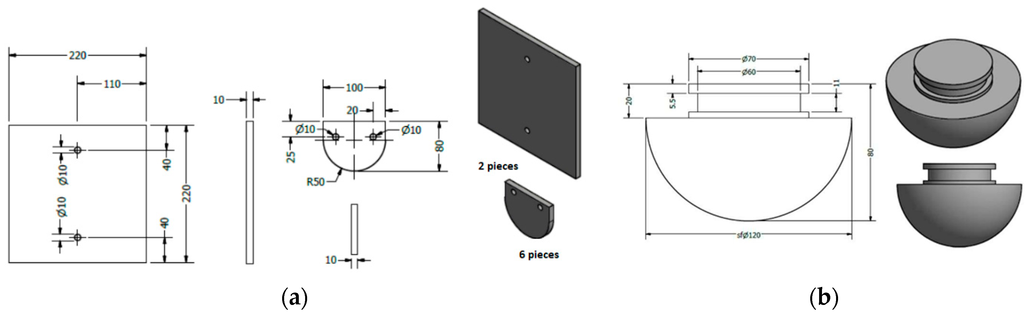
3. General Testing Procedure
4. Experimental Results and Discussions
4.1. XRD Analysis
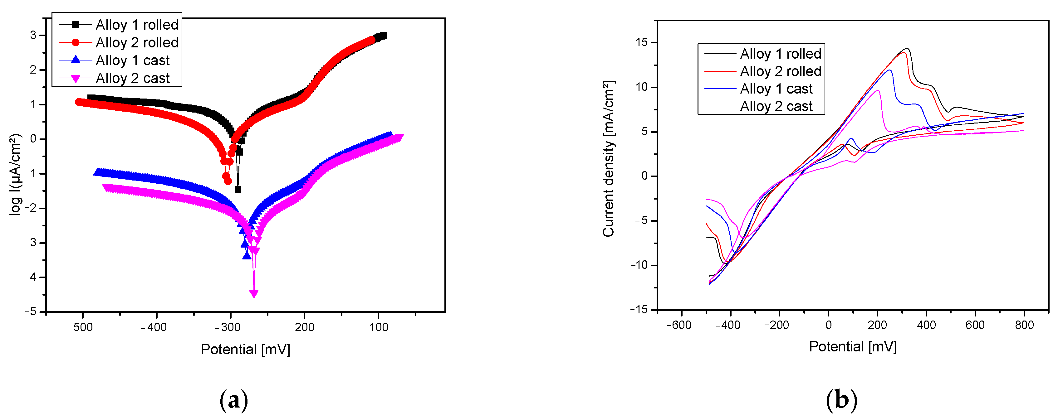
4.2. Electro-Chemical Corrosion Resistance
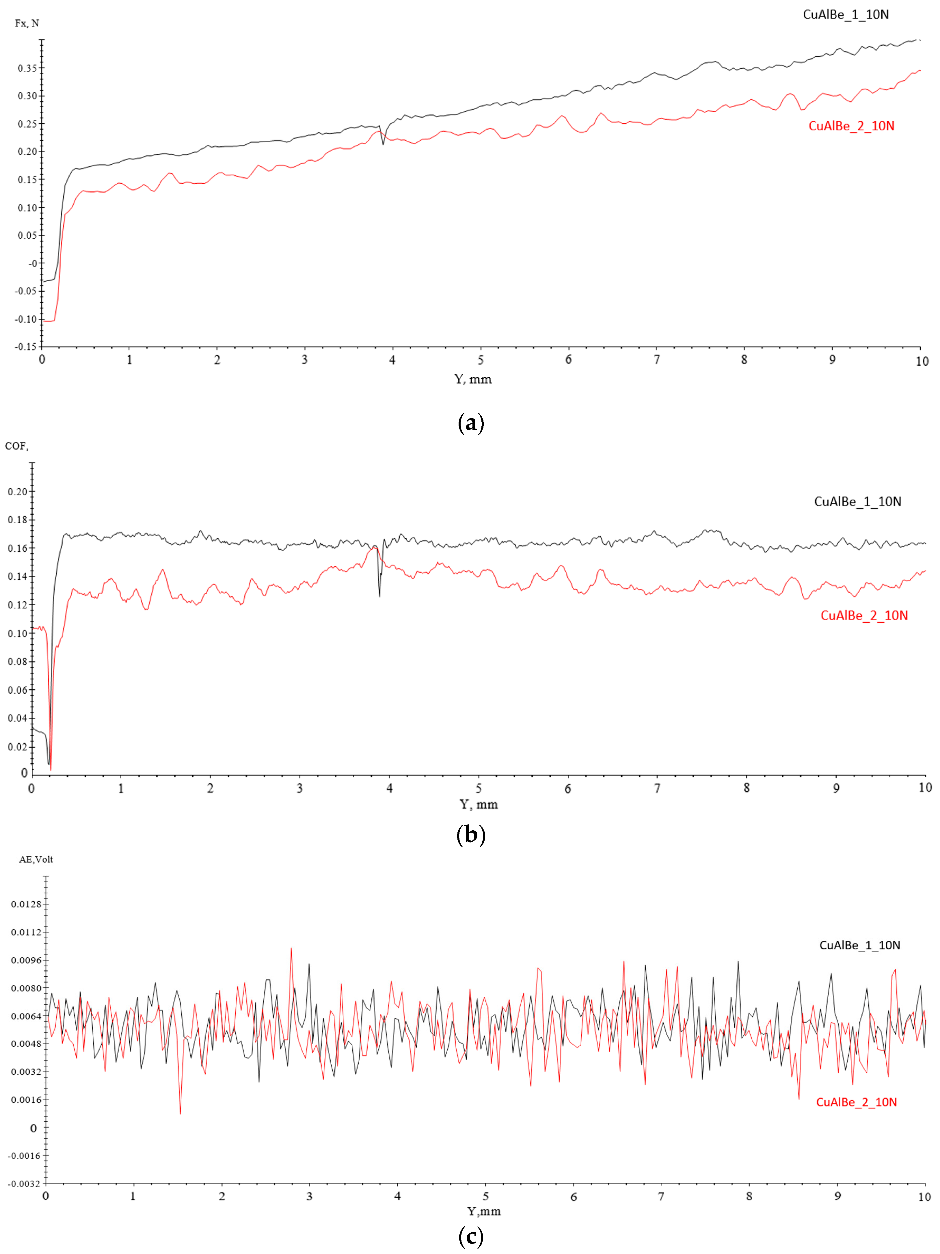
4.3. Scratch Tests Results
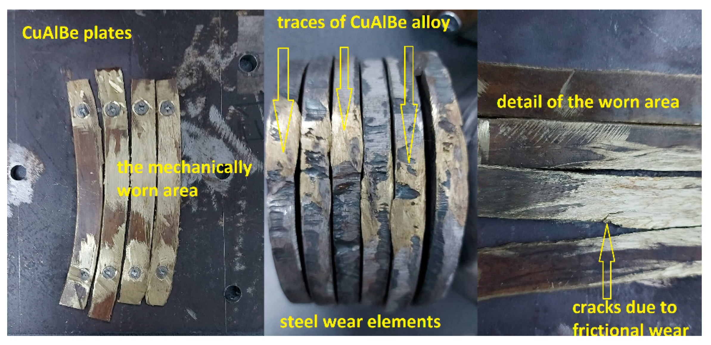
4.4. Results of Wear Tests for Hot Spark Generation
- -
- There was no ignition during the first 16,000 friction cycles in the explosive mixture;
- -
- No more than eight ignitions occurred during the next 16,000 friction cycles in the explosive mixture enriched with oxygen up to 25%.
5. Conclusions
- -
- In addition to serving as dedicated materials for non-sparking metallic parts, CuAlBe alloys can be used as non-sparking materials for various industrial applications involving potentially explosive atmospheres;
- -
- Using alloys in a rolled state without heat treatment does not affect the type of sparks produced;
- -
- Following the hot rolling of the alloys, their corrosion resistance increases at least eight times, reducing the chances of producing sparks capable of causing explosions;
- -
- The small percentage variation of Be in the tested alloy does not significantly affect its corrosion resistance or mechanical properties;
- -
- The severe wear experiments performed over 16,000 cycles and including material transfer did not produce sparks causing explosions, regardless of the component phases of the alloy.
Author Contributions
Funding
Institutional Review Board Statement
Informed Consent Statement
Data Availability Statement
Conflicts of Interest
References
- Kalyanam, S.; Sankaran, P.N. Accidental Histories in Composite Propellant Processing and Safety Measures; Report No. ISRO-SHAR-TR-08–059-91; Shar Centre: Sriharikota, India, 1991. [Google Scholar]
- Bond, J. Sources of Ignition: Flammability Characteristics of Chemicals and Chemical Products; Butterworth–Heinemann: Oxford, UK, 1991. [Google Scholar]
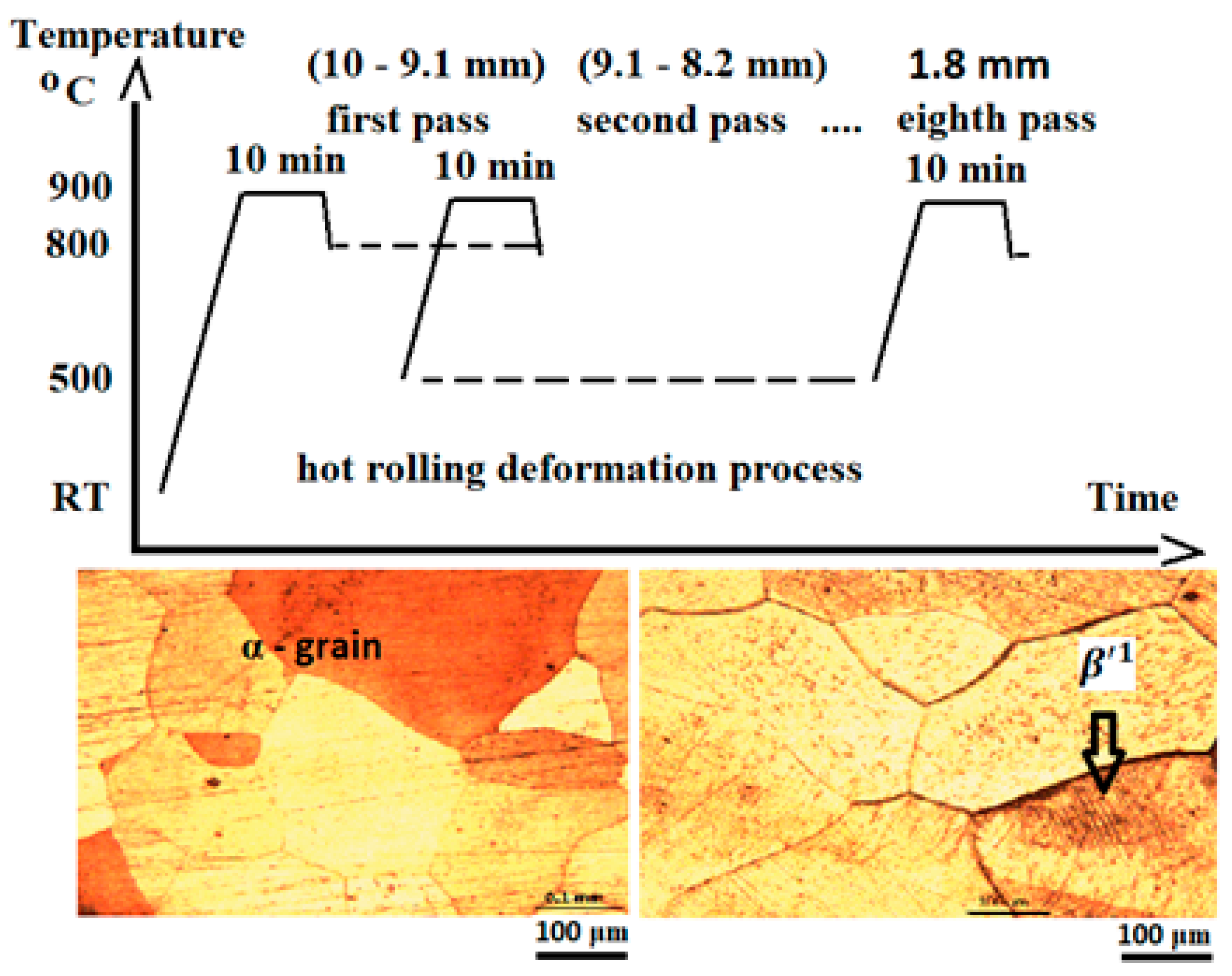
- Chelariu, G.R.; Cimpoesu, N.; Paraschiv, P.; Prisecariu, B.A.; Rusu, I.; Stirbu, I.; Sandu, G.I.; Benchea, M.; Bejinariu, C. Structural and Mechanical Properties of Hot Rolled CuAlBe Non-Spark Alloy. Arch. Metall. Mater. 2024, 69, 263–268. [Google Scholar] [CrossRef]
- Huang, L.D.; Yan, C.; Zhou, Y.; Yan, W. Multi-directional forging and aging treatment effects on friction and wear characterization of aluminium-bronze alloy. Mater. Charact. 2020, 167, 110511. [Google Scholar]
- Andrusca, L.; Goanta, V.; Barsanescu, P.D.; Savin, A. Experimental characterization of materials subjected to combined loading conditions. Mater. Sci. Eng. 2016, 147, 012092. [Google Scholar] [CrossRef]
- Chelariu, R.G.; Cimpoeșu, N.; Cazac, A.M.; Bernevig, M.A.; Bejinariu, C. Optical evaluation of the surfaces of the CuAlBe samples after the test of resistance to harsh wear stresses in an explosive atmosphere. MATEC Web Conf. 2024, 389, 00067. [Google Scholar] [CrossRef]
- Singh, R.K.; Murigendrappa, S.; Kattimani, S. Investigation on Properties of Shape Memory Alloy Wire of Cu-Al-Be Doped with Zirconium. J. Mater. Eng. Perform. 2020, 29, 11. [Google Scholar] [CrossRef]
- Canbay, A.C.; Oktay, K.; Ünlü, N.; Özkul, I. Study on Basic Characteristics of CuAlBe Shape Memory Alloy. Braz. J. Phys. 2020, 51, 13–18. [Google Scholar] [CrossRef]
- Cimpoesu, R.H.; Pompilian, G.O.; Baciu, C.; Cimpoesu, N.; Nejneru, C.; Agop, M.; Gurlui, S.; Focsa, C. Pulsed laser deposition of poly (L-Lactide) acid on nitinol substrate. Optoelectron. Adv. Mat. 2010, 4, 2148–2153. [Google Scholar]
- Da Mota Candidoa, G.V.; Ferreira de Oliveira, D.; Brito, I.C.A.; Evaristo Caluête, R.; da Silva Andrade, B.H.; Guedes de Lima Cavalcante, D. Effect of Hot Rolling on the Thermomechanical Properties of a Superelastic Cu-Al-Be-Cr Alloy. Mat. Res. 2020, 23, e20190542. [Google Scholar] [CrossRef]
- STAS 10449-86; Electrical Equipment for Potentially Explosive Atmospheres Impact and Friction Testing. The Romanian Standardization Institute: Bucharest, Romania, 1986.
- SR EN ISO/IEC 17025; General Requirements for the Competence of Testing and Calibration Laboratories. The Romanian Standardization Institute: Bucharest, Romania, 2018.
- Bejinariu, C.; Darabont, D.C.; Baciu, E.R.; Ionita, I.; Sava, M.A.B.; Baciu, C. Considerations on the Method for Self Assessment of Safety at Work. Environ. Eng. Manag. J. 2017, 16, 1395–1400. [Google Scholar]
- Pedrosa, M.; Silva, D.; Brito, I.; Alves, R.; Caluête, R.; Gomes, R.; Oliveira, D. Effects of hot rolling on the microstructure, thermal and mechanical properties of CuAlBeNbNi shape memory alloy. Thermochim. Acta 2022, 711, 179188. [Google Scholar] [CrossRef]
- Montecinos, S.; Cuniberti, A. Effects of grain size on plastic deformation in a β CuAlBe shape memory alloy. Mater. Sci. Eng. A 2014, 600, 176–180. [Google Scholar] [CrossRef]
- Montecinos, S.; Simison, S. Corrosion behavior of Cu-Al-Be shape memory alloys with different compositions and microstructures. Corros. Sci. 2013, 74, 387–395. [Google Scholar] [CrossRef]
- Darabont, D.-C.; Moraru, R.I.; Antonov, A.E.; Bejinariu, C. Managing new and emerging risks in the context of ISO 45001 standard. Qual.-Access Success 2017, 18, 11–14. [Google Scholar]
- Aksu Canbay, C.; Aydoğdu, A. Thermal analysis of Cu-14.82 wt% Al-0.4 wt% Be shape memory alloy. J. Therm. Anal. Calorim. 2013, 113, 731–737. [Google Scholar] [CrossRef]
- Canbay, C.A.; Karaduman, O.; Özkul, İ. Investigation of varied quenching media effects on the thermodynamical and structural features of a thermally aged CuAlFeMn HTSMA. Phys. B Cond. Matt. 2019, 557, 117–125. [Google Scholar] [CrossRef]
- Desroches, R.; Smith, B. Shape memory alloys in seismic resistant design and retrofit: A critical review of their potential and limitations. J. Earthq. Eng. 2003, 7, 1–15. [Google Scholar] [CrossRef]
- Jani, J.M.; Leary, M.; Subic, A.; Gibson, M.A. A review of shape memory alloy research, applications and opportunities. Mater. Des. 2014, 56, 1078–1113. [Google Scholar] [CrossRef]
- Montecinos, S.; Simison, S.N. Study of the corrosion products formed on a multi-phase CuAlBe alloy in a sodium chloride solution by micro-Raman and in situ AFM measurements. Appl. Surf. Sci. 2011, 257, 7732–7738. [Google Scholar] [CrossRef]
- Montecinos, S.; Klímek, P.; Sláma, M.; Suarez, S.; Simison, S. Corrosion behavior of a β CuAlBe shape memory alloy containing stress induced martensite. Appl. Surf. Sci. 2018, 466, 165–170. [Google Scholar] [CrossRef]
- Kear, G.; Barker, B.D.; Walsh, F.C. Electrochemical corrosion of unalloyed copper in chloride media—A critical review. Corros. Sci. 2004, 46, 109–135. [Google Scholar] [CrossRef]
- Hrituc, A.; Ermolai, V.; Mihalache, A.M.; Andrusca, L.; Dodun, O.; Nagît, G.; Boca, M.A.; Slatineanu, L. Compressive Behavior of Some Balls Manufactured by 3D Printing from Ceramic-Polymer Composite Materials. Micromachines 2024, 15, 150. [Google Scholar] [CrossRef]
- Cimpoesu, N.; Axinte, M.; Hanu, R.C.; Nejneru, C.; Achitei, D.C.; Stanciu, S. Behavior simulation of a copper-based shape memory alloy under an external solicitation. JOAM 2010, 12, 1772–1776. [Google Scholar]
- Wasmer, P.M.; Mussot-Hoinard, G.; Berveiller, S.; Patoor, E.; Eberhardt, A. Kinetics of precipitation and mechanical behavior of CuAlBe single crystal drawn-wires. ESOMAT 2009, 2009, 06023. [Google Scholar]
- Montecinos, S.; Cuniberti, A.; Sepúlveda, A. Grain size and pseudoelastic behaviour of a Cu-Al-Be alloy. Mater. Charact. 2008, 59, 117–123. [Google Scholar] [CrossRef]
- Hautcoeur, A.; Eberhardt, A.; Patoor, E.; Berveiller, M. Thermomechanical behaviour of monocrystalline Cu-Al-Be shape memory alloys and determination of the me-tastable phase diagram. J. Phys. IV 1995, 5, 459–464. [Google Scholar]
- Hugo de Albuquerque, V.; Antonio de Melo, T.; Gomes, R.; Jackson de Lima, S.; Tavares, T.M. Grain size and temperature influence on the toughness of a CuAlBe shape memory alloy. Mater. Sci. Eng. A 2010, 528, 459–466. [Google Scholar] [CrossRef]
- De Oliveira, D.F.; De Lima, J.S.G.; Brito, I.C.A.; Gomes, R.M.; Melo, T.A. Mechanical strength evaluation of a CuAlBe shape memory alloy under different thermal conditions. MSF 2010, 643, 105–111. [Google Scholar] [CrossRef]
- Al-Haidary, J.T.; Mustafa, A.M.; Hamza, A.A. Effect of Heat Treatment of Cu-Al-Be Shape Memory Alloy on Microstructure, Shape Memory Effect and Hardness. J. Mat. Sci. Eng. 2017, 6, 6. [Google Scholar] [CrossRef]


| Chemical Composition | Cu % | Al % | Be % | Others % | |||
|---|---|---|---|---|---|---|---|
| wt | at | wt | at | wt | at | wt% | |
| Alloy 1 | 90.5 | 78 | 8.5 | 17.2 | 0.8 | 4.8 | 0.2 |
| Alloy 2 | 91.0 | 79.2 | 8.4 | 17.3 | 0.4 | 2.5 | 0.2 |
| Alloy | Corrosion Process Parameters | |||||
|---|---|---|---|---|---|---|
| E (I = 0) (mV) | icorr (µA/cm) | Rp (kohm/cm) | vcorr (μm/an) | −βc (mV/dec) | βa (mV/dec) | |
| Alloy 1, cast | −278.9 | 31.6 | 1.86 | 436.0 | 378.0 | 122.2 |
| Alloy 2, cast | −268.5 | 30 | 3.77 | 414.5 | 725.2 | 123.8 |
| Alloy 1, rolled | −290.3 | 3.73 | 5.84 | 51.45 | 314.4 | 122.3 |
| Alloy 2, rolled | −306.1 | 3.49 | 14.53 | 48.11 | 379.6 | 83.0 |
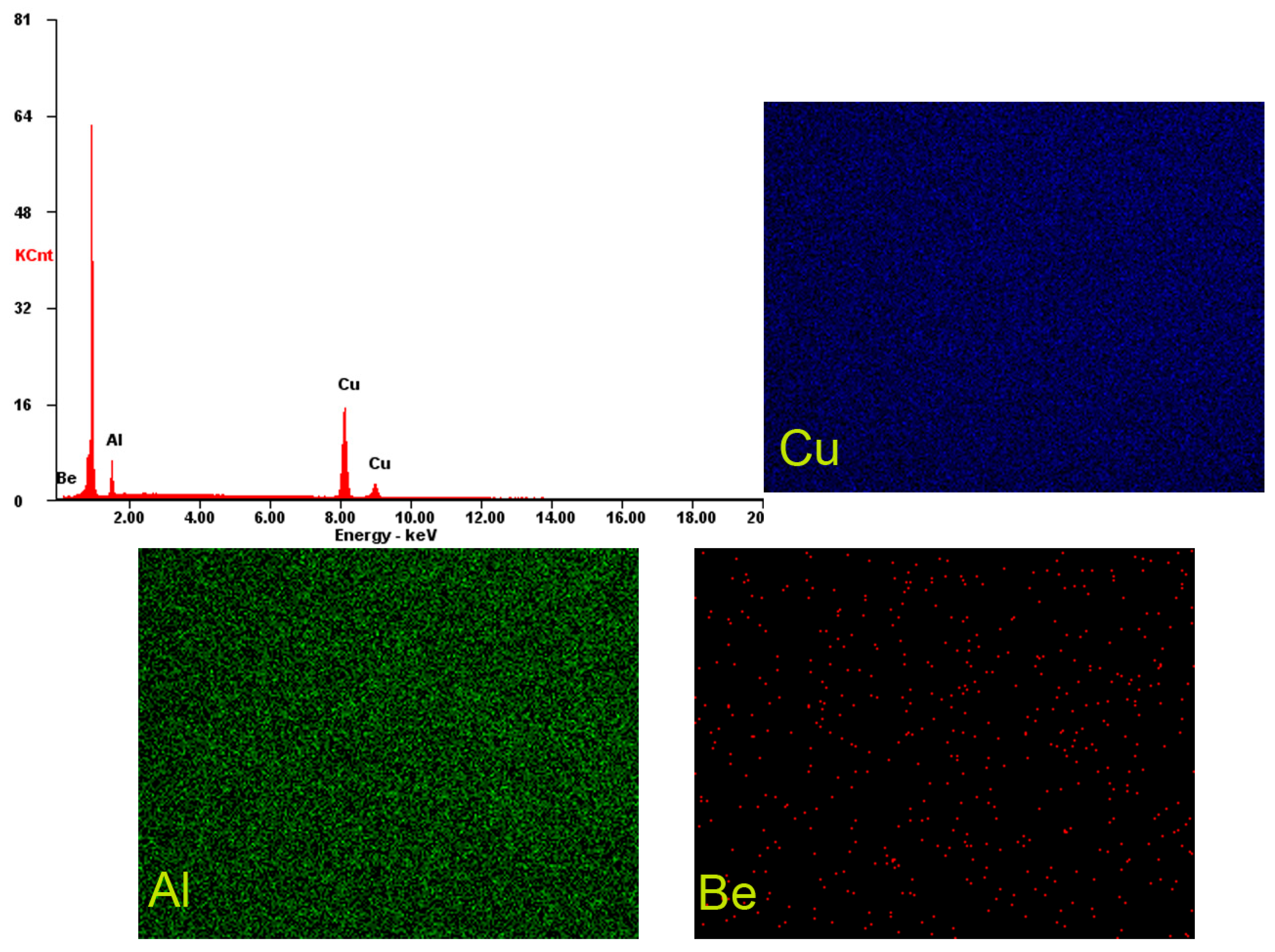
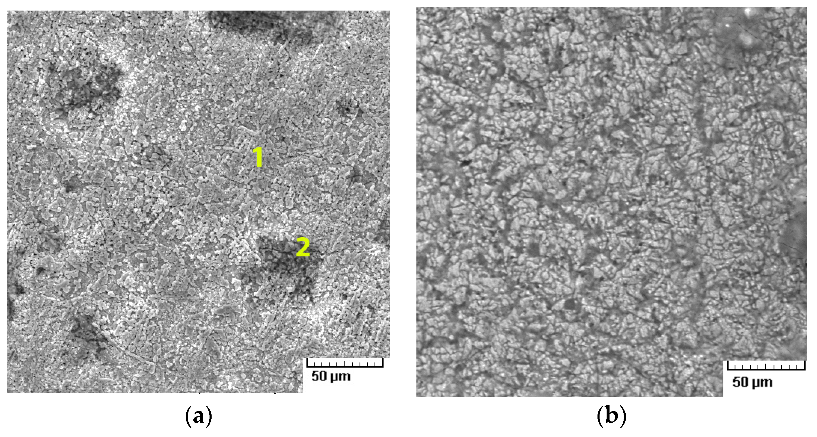
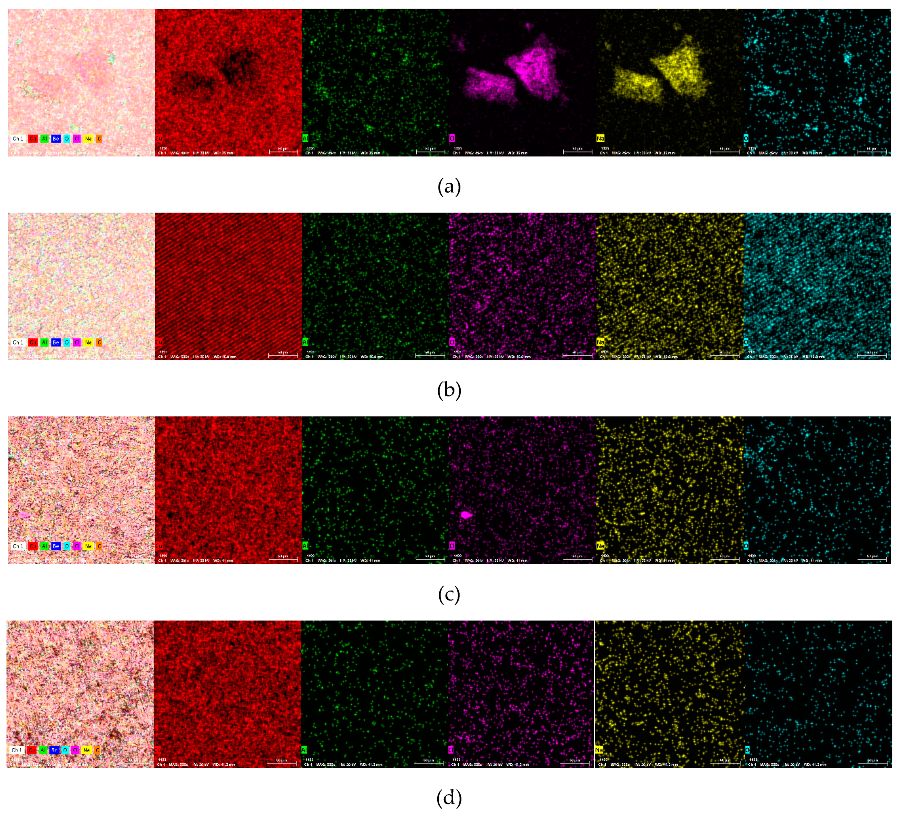
| Surface | Alloy 1 Cast | Alloy 2 Cast | Alloy 1 Hot-Rolled | Alloy 2 Hot-Rolled | EDS Error % | |
|---|---|---|---|---|---|---|
| Cu % | wt | 79.79 | 68.05 | 87.39 | 86.45 | 1.5 |
| at | 53.24 | 34.45 | 56.68 | 55.64 | ||
| Al % | wt | 0.55 | 0.89 | 0.32 | 0.17 | 0.1 |
| at | 0.86 | 1.06 | 0.48 | 0.26 | ||
| Be % | wt | - | - | 3.23 | 2.69 | 0.01 |
| at | - | - | 14.75 | 12.22 | ||
| Na % | wt | 9.02 | 4.88 | 1.23 | 2.01 | 3.93 |
| at | 16.65 | 6.82 | 2.21 | 3.58 | ||
| C % | wt | 6.13 | 9.82 | 6.91 | 7.51 | 10 |
| at | 21.65 | 26.32 | 23.70 | 25.60 | ||
| Cl % | wt | 2.98 | 1.38 | 0.16 | 0.18 | 1.2 |
| at | 3.57 | 1.26 | 0.18 | 0.20 | ||
| O % | wt | 1.54 | 14.98 | 0.77 | 0.97 | 0.5 |
| at | 4.04 | 30.11 | 1.98 | 2.50 | ||
| Materials | Fx [N] | AE [V] | CoF | Ff [N] | −Fz [N] |
|---|---|---|---|---|---|
| CuAlBe_1_10N | 0.043 | 0.0058 | 0.179 | 1.043 | 5.24 |
| CuAlBe_2_10N | 1.71 | 0.006 | 0.274 | 1.713 | 5.47 |
| Nr. Crt. | Sample Type | Explosive Mixture (10% H2) or 6.5%CH4 | Pair of Materials | Occurrence of Ignition during the First 16,000 Friction Cycles in Explosive Mixture (YES/NO) | Occurrence of Ignition during the First 16,000 Friction Cycles in Explosive Mixture Enriched with O2 up to 25% (YES/NO) |
|---|---|---|---|---|---|
| 1. | Samples CuAlBe_1 | 10% H2 | F1-CuAlBe_1 and steel | NO | NO |
| 2. | Samples CuAlBe_2 | 10% H2 | F1-CuAlBe_2 and steel | NO | NO |
Disclaimer/Publisher’s Note: The statements, opinions and data contained in all publications are solely those of the individual author(s) and contributor(s) and not of MDPI and/or the editor(s). MDPI and/or the editor(s) disclaim responsibility for any injury to people or property resulting from any ideas, methods, instructions or products referred to in the content. |
© 2024 by the authors. Licensee MDPI, Basel, Switzerland. This article is an open access article distributed under the terms and conditions of the Creative Commons Attribution (CC BY) license (https://creativecommons.org/licenses/by/4.0/).
Share and Cite
Chelariu, R.G.; Cimpoesu, R.; Jurca, A.M.; Popa, C.M.; Benchea, M.; Badarau, G.; Istrate, B.; Cazac, A.M.; Cimpoesu, N.; Pintilie, D.-D.; et al. Analysis of Chemical, Microstructural and Mechanical Properties of a CuAlBe Material Regarding Its Role as a Non-Sparking Material. Materials 2024, 17, 2220. https://doi.org/10.3390/ma17102220
Chelariu RG, Cimpoesu R, Jurca AM, Popa CM, Benchea M, Badarau G, Istrate B, Cazac AM, Cimpoesu N, Pintilie D-D, et al. Analysis of Chemical, Microstructural and Mechanical Properties of a CuAlBe Material Regarding Its Role as a Non-Sparking Material. Materials. 2024; 17(10):2220. https://doi.org/10.3390/ma17102220
Chicago/Turabian StyleChelariu, Romeo Gabriel, Ramona Cimpoesu, Adrian Marius Jurca, Catalin Mihai Popa, Marcelin Benchea, Gheorghe Badarau, Bogdan Istrate, Alin Marian Cazac, Nicanor Cimpoesu, Dan-Dumitru Pintilie, and et al. 2024. "Analysis of Chemical, Microstructural and Mechanical Properties of a CuAlBe Material Regarding Its Role as a Non-Sparking Material" Materials 17, no. 10: 2220. https://doi.org/10.3390/ma17102220