
Preparation of Sr2CeZrO6 Refractory and Its Interaction with TiAl Alloy
by
 and
and
Fuli Bian
1,
Zheyu Cai
2,
Jian Liu
2,
Yu Liu
2,
Man Zhang
2,
Yixin Fu
2,
Kailiang Zhu
1,
Guangyao Chen
2,3,4,* and
Chonghe Li
2,3,4,* 1
Fire Research Institute of Shanghai of MEM, Shanghai 200032, China
2
State Key Laboratory of Advanced Special Steel & Shanghai Key Laboratory of Advanced Ferrometallurgy & School of Materials Science and Engineering, Shanghai University, Shanghai 200444, China
3
Shanghai Special Casting Engineering Technology Research Center, Shanghai 201605, China
4
Zhejiang Institute of Advanced Materials, Shanghai University, Jiaxing 314100, China
*
Authors to whom correspondence should be addressed.
Materials 2023, 16(23), 7298; https://doi.org/10.3390/ma16237298
Submission received: 18 October 2023
/
Revised: 10 November 2023
/
Accepted: 21 November 2023
/
Published: 23 November 2023
(This article belongs to the Special Issue Heat Treatments and Performance of Alloy and Metal)
Abstract
:Vacuum induction melting in a refractory crucible is an economical method to produce TiAl-based alloys, aiming to reduce the preparation cost. In this paper, a Sr2CeZrO6 refractory was synthesized by a solid-state reaction method using SrCO3, CeO2 and ZrO2 as raw materials, and its interaction with TiAl alloy melt was investigated. The results showed that a single-phase Sr2CeZrO6 refractory could be fabricated at 1400 °C for 12 h, and its space group was Pnma with a = 5.9742(3) Å, b = 8.3910(5) Å and c = 5.9069(5) Å. An interaction layer with a 40μm thickness and dense structure could be observed in Sr2CeZrO6 crucible after melting TiAl alloy. Additionally, the interaction mechanism showed that the Sr2CeZrO6 refractory dissolved in the alloy melt, resulting in the generation of Sr3Zr2O7, SrAl2O4 and CeO2−x, which attached to the surface of the crucible.
1. Introduction
TiAl alloys have been considered as novel lightweight construction materials due to their low density (approximately 4.0 g/cm3) and high specific strength [1]. They have the potential to replace heavier Ni-based superalloys, resulting in weight reduction and enhancing the thrust-to-weight ratio [2,3]. Although TiAl alloys have substantial performance advantages, their elevated production costs are a factor limiting their further development [4,5].
Investment casting technology with induction skull melting (ISM) has been the commercial method for the manufacture of TiAl alloy parts [6]. However, the implementation of ISM significantly influences the ultimate cost of the casting products, which has contributed to the elevated levels of casting rejections. This is because this method does not easily achieve suitable superheating. In order to solve this problem, a suitable preheat temperature for the casting mold should be used. This results in the occurrence of the melt–mold interaction, and solidification defects are thus also introduced. Vacuum induction melting (VIM) of TiAl alloys using the refractory crucibles offers a viable approach to attaining optimal superheating and reducing the production expenses. However, the key problems are the selection of exceptionally stable and cost-effective refractory in crucible manufacturing [7,8,9,10].
Until now, researchers have explored various oxide materials as refractory crucibles for melting TiAl alloys, such as Y2O3 [11], CaO [12], ZrO2 [13] and Al2O3 [14]. However, these refractory materials applied for melting TiAl alloy also have shortcomings [15]. Toshimitsu demonstrated the feasibility of melting TiAl alloys in crucibles made of Y2O3, ZrO2, and Al2O3 [13]. Notably, the oxygen levels in the TiAl alloy were relatively low (0.12 wt.%) using the Y2O3 crucible. In contrast, the absorption of oxygen from the ZrO2 and Al2O3 crucibles occurred at a notably higher level (0.96 and 1.57 wt.%, respectively). Koichi’s work presented that the oxygen concentration could be controlled at 0.1–0.13 wt.% with a holding smelting time ranging from 5 to 20 min in the CaO crucible [16]. From a thermodynamic perspective, Y2O3 and CaO had higher stability than that of Al2O3 and ZrO2. Thus, they were more suitable for melting TiAl alloys. However, there are significant challenges that need to be addressed before industrial-scale manufacture. For instance, Y2O3 has an inherent drawback of poor thermal shock resistance, and CaO exhibits a hygroscopic nature [17,18]. Given these considerations, it becomes imperative to explore and develop a new stable refractory for the melting of TiAl alloys.
Novel alkaline earth zirconate materials, such as Sr-Zr oxides, exhibit the essential properties for melting titanium alloys. For example, SrZrO3 was an attractive candidate material due to its exceptional resistance to corrosion, especially in alkaline melts and vapors [19]. Generally, compounds with perovskite ABX3 structure are very well-known inorganic materials. The A and B sites in perovskite materials possess the capability to accommodate diverse metal cations, providing an avenue to regulate both the chemical compositions and the properties of perovskite materials. Substituting elements on the B sites can lead to the formation of double perovskite A2B′B″O6 compounds, where A represents an alkaline-earth metal, and B′ and B″ represent two different transition metal elements. The positioning of B′ and B″ cations within the crystal structure can vary, either occupying indistinguishable sites or distinct sites, contingent upon their charge and ionic radii. Double perovskites exhibit a wide array of intriguing properties owing to their diverse compositions and structures, prompting extensive investigations into their structural characteristics [20]. In order to develop an Sr-Zr series perovskite oxide refractory for melting titanium alloys, our group attempted to prepare a novel refractory by doping rare earth elements, followed by evaluating their stability for melting titanium alloys [21]. The rare oxide such as CeO2 has a high melting point (nearly 1950 °C). It is typically stable at high temperatures, making it potentially useful in high-temperature applications, such as in high-temperature lubricants or coating materials [22]. In this study, CeO2 was introduced into the preparation of the Sr-Zr oxide refractory. It could be considered that the Ce dopant could replace the position of Zr elements in the Sr-Zr oxides. Thus, a double perovskite structure Sr2CeZrO6 refractory was fabricated, and then its interaction with melting TiAl alloys was investigated. Until now, there have not been any prior exploration into utilizing Sr2CeZrO6 refractory for preparing TiAl alloys.
In this paper, firstly, the manufacturing process involved the synthesis of a Sr2CeZrO6 refractory through a solid-state approach utilizing industrial-grade SrCO3, CeO2 and ZrO2 raw materials. Subsequently, the formation of the Sr2CeZrO6 crucible was achieved via shaping and sintering. Utilizing XRD and SEM, the synthesized powders were analyzed to ascertain the phase composition and microstructure. The structure of Sr2CeZrO6 refractory was investigated through the Rietveld method. Subsequently, TiAl alloy was melted in the Sr2CeZrO6 crucible, facilitating an exploration into the interaction between the TiAl alloy and Sr2CeZrO6 crucible, along with an investigation into the corresponding interaction mechanism.
2. Experiment
SrCO3 (99.9%), ZrO2 (99.9%) and CeO2 (99.9%) raw materials were employed for the preparation of a SrCeZrO6 refractory according to the solid-state reaction. The XRD (Bruker GADDS, Cambridge, MA, USA) patterns for the raw materials are shown in Figure 1. The raw materials were accurately measured following a mole ratio of n(SrCO3): n(ZrO2): n(CeO2) = 2:1:1. Subsequently, they were subjected to ball milling (MD-2 L, Nanjing, China), followed by drying at 120 °C for 12 h. Then, the discs with φ20 mm × 3 mm were fabricated at 120 MPa, holding for 2 min. Finally, the unfired discs were heat-treated at 1400 °C for 12 h.
Prior to the phase analysis, the sintered discs were ground into powders and then sieved through a 400-mesh sieve. XRD was used to analyze the phase structure of the powders through Rietveld refinement via GSAS-II software (https://subversion.xray.aps.anl.gov/trac/pyGSAS). Microstructure analysis was carried out using scanning electron microscopy (FEI Nova nano SEM450, Sydney, Austria).
The Sr2CeZrO6 refractory material underwent cold isostatic pressing to form crucibles using a U-shaped steel mandrel measuring 3.5 cm in width and 4.5 cm in height. in this shaping process, a pressure of 120 MPa was applied for a duration of 3 min. Then, the crucible biscuits were sintered at 1700 °C and held for 4 h. The slow heating rate of 2 °C/min was carefully controlled to prevent the formation of cracks.
Our goal was to assess the interface stability between the Sr2CeZrO6 refractory and the TiAl alloy melt. Before the melting experiment, a TiAl master alloy with an equimolar ratio was prepared using Al pellets (>99.99%) and sponge Ti (>99.9%) in a water-cooled copper crucible. In the VIM furnace, the space surrounding the crucible was filled with Al2O3 ramming mass. Then, the master alloy was inserted into the crucible. The furnace chamber was evacuated to 10−3 mbar. The high-purity argon gas was backfilled into the chamber at least three times. This effectively prevented oxygen contamination during the melting. As the molten alloy became visible, high-purity argon gas was reintroduced, and the temperature was slowly raised to 1600 °C and maintained for 5 min. Then, the alloy melt was allowed to cool in the crucible. X-ray diffraction was used to analyze the crucible surface in order to examine the interaction products between them. The interaction behavior was investigated after the fabrication of the samples using a buzz saw. Selected sections underwent examination using a digital microscope (VHX-1000). Interaction analyses for the microstructure were conducted using a scanning electron microscope with an energy dispersive spectrometer (EDS).
3. Results and Discussion
3.1. Synthesis of Sr2CeZrO6 Powder
Figure 2 shows the powder synthesized using SrCO3, CeO2 and ZrO2 after sintering at 1400 °C for 12 h. The sintered powder exhibited a significant sintering phenomenon, as shown in Figure 2a. After the crushing process, the edges of the powder were distinct, indicating that this synthesized condition was sufficient for preparing this refractory. Figure 2b depicts the backscatter electron (BSE) image from Figure 2a. It can be seen that the synthesis degree of this compound was good. Furthermore, chemical element mapping of Sr, Ce, Zr, and O was carried out (Figure 2b–f). The uniform distribution of these elements is evident, showing no signs of accumulation or segregation.
To further confirm the crystal structure of Sr2CeZrO6, the XRD pattern of the sintered powder was refined by the Rietveld method. The Rietveld refinement of the XRD data of the powder in the 2θ° angle 10~120° is shown in Figure 3. Indexing of the XRD spectra by Jade 6.0 program revealed that Sr2CeZrO6 had a similar peak pattern to SrCeO3 (Pnma 62). Therefore, the XRD data of the Sr2CeZrO6 sample were refined using the orthogonal structure Pnma space group. In this structural model, Sr atoms occupied the 4c position at coordinates (0.45, 025, 0), while both Ce and Zr atoms occupied the 4a position (0, 0, 0) with an equal occupancy of 0.5:0.5. O atoms were positioned at 4c (0, 0.25, 0) and 8d (0, 0, 0.2). Figure 3 illustrates the refined structural model of the Sr2CeZrO6. The experimental intensity (depicted by the green dotted line) of the Sr2CeZrO6 coincided with the simulated intensity (shown as the red continuous line). The lattice constants were a = 5.9742(3) Å, b = 8.3910(5) Å, c = 5.9069(5) Å, respectively, with a unit cell volume of 296.11(6) Å3 using the least-squares method. The reliability factors Rwp and GOF stood at 8.94% and 1.57, respectively. This indicated that the Rietveld refinements were conducted at a reasonably high standard. Table 1 outlines the refined structural parameters of the Sr2CeZrO6.
3.2. Phase Constitution of Sr2CeZrO6 Crucible
The SEM picture of the Sr2CeZrO6 crucible surface after sintering at 1700 °C and holding for 4 h is shown in Figure 4. The backscatter electron (BSE) picture in Figure 4a showed that the crucible consisted of a single phase. The sintering process of the crucible was undertaken in a silicon molybdenum rod furnace with an air atmosphere. During the prolonged calcination process, substances inside the furnace lining could volatilize and deposit on the surface of the crucible, resulting in the formation of some impurities. Table 2 indicates the EDS results of spots 1 and 2. It can be seen that the grains in the crucible surface consisted of Sr, Ce, Zr and O elements, which was consistent with the theoretical ratio. The XRD pattern in Figure 4b shows that only the Sr2CeZrO6 phase could be detected on the crucible surface, confirming the analysis in Figure 4a.
3.3. Interfacial Interaction
The macroscopic picture of the cooled alloy and the crucible is shown in Figure 5. Evidently, the alloy was separated from the crucible matrix. In the process of the melting, the alloy with its high chemical activity was able to permeate into the crucible refractory, resulting in the generation of a black area (contact layer). Due to the rapid heating rate during the melting process, some cracks were generated. In the future, decreasing the heating rate should be considered in order to reduce the occurrence of cracks. Additionally, the integrity of the crucible was not changed. The detailed analysis is described below.
The macroscopic pictures of the cross-sections of the crucibles before and after melting are shown in Figure 6. Before the melting, the crucible displayed a glossy yellow sheen, and the inner wall of the crucible was flat, as shown in Figure 6a. From Figure 6b, it can be seen that the crucible exhibited a black-gray color. Additionally, there was no significant erosion layer observed.
Figure 7 shows the microstructure of the crucible surface before and after the melting. As shown in Figure 7a, a smooth surface could be observed before the melting, and the boundaries were obvious. However, after the melting, the crucible surface appeared uneven, and the grain boundaries had disappeared. Evidently, during the melting, the crucible surface corroded. Figure 7c shows the magnified picture of area A in Figure 7b. A combination of block and strip grains appeared on the crucible surface, as shown in Figure 7c. Table 3 exhibited that the grains with the block shapes consisted of Sr, Zr, Ce and O elements. The XRD pattern for the crucible surface in Figure 7d shows that it consisted of Sr3Zr2O7, CeO2−x and SrAl2O4 phases. This can be elucidated in conjunction with the suggested interaction model outlined below.
The SEM pictures of the cross-section of the crucibles before and after melting are shown in Figure 8. As shown in Figure 8a, the inner wall of the crucible was flat, and some pores were observed in the crucible matrix. EDS results in Table 4 show that the crucible matrix (spots 8 and 9) consisted of an Sr2CeZrO6 phase. After melting, an interaction layer (~40 μm thickness) and dense structure could be observed in the crucible, as shown in Figure 8b. EDS results indicated that the crucible matrix (spot 10) exhibited a different elementary composition from the interaction layer (spots 11 and 12). As shown in Figure 8d–f, there was a large number of Al elements, which were enriched in the interaction layer. Additionally, the Zr elements exhibited a clear downward trend in the interaction layer in comparison with those in the crucible matrix. It can be concluded that a movement of Al and Zr elements occurred during the interaction between them. Actually, because of the similar structures of the Zr and Ti elements, both of them exhibited excellent compatibility, resulting in the easy dissolution of Zr elements into the alloy melt. From the analysis in Figure 7, it can be seen that the Al reacted with the decomposed refractory to generate SrAl2O4, resulting in the enrichment of Al elements in the interaction layer. Additionally, there were essentially no Ti elements, which were residual along the crucible sidewall. This indicated that this refractory exhibited a good non-wettability during the alloy melts, consistent with the analysis in Figure 7c.
The detailed electronic states of the constituent elements in the interaction layer were characterized by X-ray photoelectron spectroscopy (XPS) measurements, as shown in Figure 9. It can be seen that the valence states of Sr and Zr were both in the positive tetravalent state, corresponding to the valence states in SrTiO3 and ZrO2, respectively. However, the coexistence of Ce4+ and Ce3+ was observed in this layer. This indicates that there was non-stoichiometric CeO2 in the interaction layer (i.e., CeO2−x). Evidently, the interaction between the refractory and the alloy melt caused the phase change in the interaction layer. The detailed interaction mechanism is described next.
Figure 10 illustrates the dependence of vs. the temperature for the formation of TiO2, TiO, Al2O3, CeO, ZrO2, SrO and Sr3Zr2O7, according to results obtained from the HSC software (Version 6.1). The Gibbs free energy of Sr2CeZrO6 was not confirmed. Because no interaction products, such as TiO2 and TiO, could be detected (see Figure 7d), it can be concluded that the interaction mechanism between them was still the dissolution of the crucible refractory in the alloy melt. The dissolution Equation (1) is described below:
From Figure 10, it can be seen that the decomposed product of Sr3Zr2O7 exhibited a better stability than that of TiO2 and TiO. Thus, due to the high chemical activity of the TiAl alloy melt, it further dissolved in the alloy melt, leading to the generate of SrO and the solution of Zr and O elements into the alloy melt. Additionally, CeO2 exhibited a worse stability than that of TiO. It reacted with the alloy melt, resulting in the generation of TiO. However, this reaction occurred along the solid–liquid interface, and the Ti melt exhibited a relatively high solubility with the O elements. Thus, no TiO could be detected in the crucible. The Equations (2) and (3) were showed as follows.
As the O elements dispersed along the interface between the crucible and the alloy melt, it further combined with the Al elements to generate Al2O3 products. Then, Al2O3 reacted with SrO, resulting in the generation of SrAl2O4. The reaction Equations (4) and (5) are presented below.
4. Conclusions
In this study, a novel perovskite SrCeZrO6 refractory was synthesized using the solid-state method. The interaction of the SrCeZrO6 refractory with a TiAl alloy melt was investigated. Conclusions were obtained as follows:
- (1)
- The pure compound Sr2CeZrO6 was successfully synthesized by a solid-state reaction after sintering at 1400 °C for 12 h. The Sr2CeZrO6 phase showed Pnma space group symmetry with a = 5.9742(3) Å, b = 8.3910(5) Å, c = 5.9069(5) Å.
- (2)
- The Sr2CeZrO6 refractory crucible maintained an intact shape after contacting with the TiAl alloy melt, and the thickness of the interaction layer was about 40 μm.
- (3)
- The Sr2CeZrO6 refractory decomposed into Sr3Zr2O7, SrAl2O4 and CeO2−x. The products were generated by the dissolution of the Sr2CeZrO6 refractory in the alloy melt, which was the main factor responsible for the interaction mechanism between them. This study provides some theoretical guidance for the development of new refractory materials for melting titanium alloys in the future.
Author Contributions
Conceptualization, K.Z., G.C. and C.L.; formal analysis, Z.C.; investigation, J.L.; resources, Y.L. and M.Z.; data curation, Y.F.; writing—original draft preparation, F.B.; writing—review and editing, F.B.; supervision, G.C.; project administration, F.B. All authors have read and agreed to the published version of the manuscript.
Funding
This research was supported by Science and Technology plan projects of Fire Research Institute of Shanghai (No. 22SX34), National Natural Science Foundation of China (Nos. 52001297; 52104305).
Institutional Review Board Statement
Not applicable.
Informed Consent Statement
Not applicable.
Data Availability Statement
Data are contained within the article.
Conflicts of Interest
The authors declare no conflict of interest.
References
- Wu, X. Review of alloy and process development of TiAl alloys. Intermetallics 2007, 14, 1114–1122. [Google Scholar] [CrossRef]
- Clemens, H.; Mayer, S. Design, Processing, Microstructure, Properties, and Applications of Advanced Intermetallic TiAl Alloys. Adv. Eng. Mater. 2013, 15, 191–215. [Google Scholar] [CrossRef]
- Chen, S.H.; Schumacher, G. The application of transformation matrices on the determination of γ/γ interface types in a γ-TiAl alloy. Scr. Mater. 2004, 50, 31–34. [Google Scholar] [CrossRef]
- Kim, Y.W. Trends in the development of gamma TiAl alloys. In Gamma Titanium Aluminides; Kim, Y.W., Ed.; Minerals, Metals and Materials Society: Warrendale, PA, USA, 1995; pp. 637–652. [Google Scholar]
- Yamaguchi, M. High temperature intermetallics—With particular emphasis on TiAl. Mater. Sci. Technol. 1992, 8, 299–307. [Google Scholar] [CrossRef]
- Noda, T. Application of cast gamma TiAl for automobiles. Intermetallics 1998, 6, 709–713. [Google Scholar] [CrossRef]
- Liu, K.; Ma, Y.C.; Gao, M.; Rao, G.B.; Li, Y.Y.; Wei, K.; Wu, X.H.; Loretto, M.H. Single step centrifugal casting TiAl automotive valves. Intermetallics 2005, 13, 925–928. [Google Scholar] [CrossRef]
- Sung, S.Y.; Kim, Y.J. Economic net-shape forming of TiAl alloys for automotive parts. Intermetallics 2006, 14, 1163–1167. [Google Scholar] [CrossRef]
- Lan, L.; Xin, R.Y.; Jin, X.Y.; Gao, S.; He, B.; Rong, Y.H.; Min, N. Effects of Laser Shock Peening on Microstructure and Properties of Ti–6Al–4V Titanium Alloy Fabricated via Selective Laser Melting. Materials 2020, 13, 3261. [Google Scholar] [CrossRef] [PubMed]
- Cristescu, N.D.; Craciun, E.M.; Soós, E. Mechanics of Elastic Composites; Chapman and Hall/CRC: Boca Raton, FL, USA, 2004. [Google Scholar]
- Cui, R.J.; Tang, X.X.; Gao, M.; Zhang, H.; Gong, S.K. Interactions between TiAl alloys and ytrria refractory material in casting process. J. Mater. Process. Technol. 2010, 210, 1190–1196. [Google Scholar]
- Barbosa, J.; Ribeiro, C.S.; Monteiro, A.C. Influence of superheating on casting of γ-TiAl. Intermetallics 2007, 15, 945–955. [Google Scholar] [CrossRef]
- Tetsui, T.; Kobayashi, T.; Mori, T.; Kishimoto, T.; Harada, H. Evaluation of Ytrria Applicability as a Crucible for Induction Melting of TiAl Alloy. Mater. Trans. 2010, 51, 1656–1662. [Google Scholar] [CrossRef]
- Zhang, H.R.; Tang, X.X.; Zhou, C.G.; Zhang, H.; Zhang, S.W. Comparison of directional solidification of TiAl alloys in conventional Al2O3 and novel Y2O3-coated Al2O3 crucibles. J. Eur. Ceram. Soc. 2013, 33, 925–934. [Google Scholar] [CrossRef]
- Tetsui, T.; Kobayashi, T.; Ueno, T.; Hiroshi, H. Consideration of the influence of contamination from oxide crucibles on TiAl cast material, and the possibility of achieving low-purity TiAl precision cast turbine wheels. Intermetallics 2012, 31, 274–281. [Google Scholar] [CrossRef]
- Sakamoto, K.; Yoshikawa, K.; Kusamichi, T.; Onoye, T. Changes in Oxygen Contents of Titanium Aluminides by Vacuum Induction, Cold Crucible Induction and Electron Beam Melting. Trans. Iron Steel Inst. Jpn. 1992, 32, 616–624. [Google Scholar] [CrossRef]
- Tetsui, T.; Kobayashi, T.; Kishimoto, A.; Harada, H. Structural optimization of an yttria crucible for melting TiAl alloy. Intermetallics 2012, 20, 16–23. [Google Scholar] [CrossRef]
- Li, Z.H.; Wang, Y.; Xu, K.; Yang, J.Z.; Niu, S.B.; Yao, H. Effect of steam on CaO regeneration, carbonation and hydration resistance for CO2 capture. Fuel Process. Technol. 2016, 151, 101–106. [Google Scholar] [CrossRef]
- Uwanyuze, R.S.; Yavas, B.; Zhang, J.Y.; Kanyo, J.E.; Frame, L.D.; Hebert, R.J.; Schaffoner, S.; Al, S.P. High-temperature interactions between titanium alloys and strontium zirconate refractories. J. Mater. Eng. Perform. 2023, 32, 1–11. [Google Scholar] [CrossRef]
- Zhang, Y.; Xu, X.J. Modeling oxygen ionic conductivities of ABO3 Perovskites through machine learning. Chem. Phys. 2022, 558, 111511. [Google Scholar] [CrossRef]
- Xiao, Y.B.; Chen, G.Y.; Yu, F.H.; Hou, X.; Zhang, Y.; Zou, X.L.; Lu, X.G.; Li, C.H. Preparation of a novel Sr-Zr oxide refractory for induction melting of high-activity alloy. J. Eur. Ceram. Soc. 2021, 41, 6738–6743. [Google Scholar] [CrossRef]
- Zhou, B.; Ke, Q.L.; Wen, M.J.; Ying, T.B.; Cui, G.K.; Gu, Z.Y.; Lu, H.F. Catalytic combustion of toluene on Pt/Al2O3 and Pd/Al2O3 catalysts with CeO2, CeO2-Y2O3 and La2O3 as coatings. J. Rare Earths 2023, 41, 1171–1178. [Google Scholar] [CrossRef]
Figure 1.
XRD patterns for the raw materials. (a) CeO2; (b) SrCO3; (c) ZrO2.

Figure 2.
(a) The SEM pictures of synthesized powder after maintenance at 1400 °C for 12 h; (b–f) EDS elemental mapping pictures of Sr Lα, Ce Lα, Zr Lα and O Kα.
Figure 2.
(a) The SEM pictures of synthesized powder after maintenance at 1400 °C for 12 h; (b–f) EDS elemental mapping pictures of Sr Lα, Ce Lα, Zr Lα and O Kα.
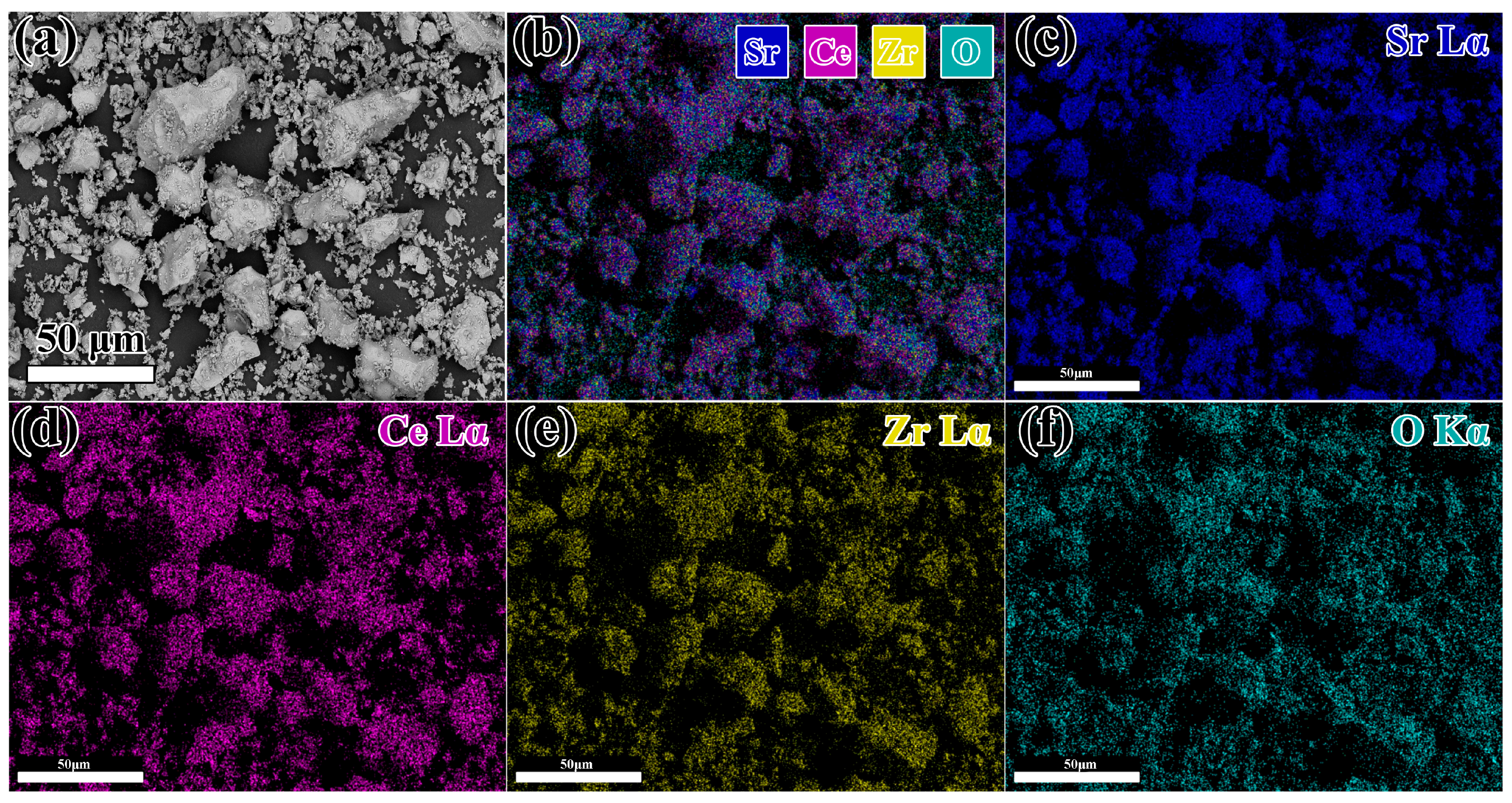
Figure 3.
Experimentally observed (dots), Rietveld-calculated (continuous line), and difference (continuous bottom line) profiles for Sr2CeZrO6 after Rietveld analysis for the XRD data using the Pnma space group. The vertical tick marks above the difference plot showed the Bragg peak positions.
Figure 3.
Experimentally observed (dots), Rietveld-calculated (continuous line), and difference (continuous bottom line) profiles for Sr2CeZrO6 after Rietveld analysis for the XRD data using the Pnma space group. The vertical tick marks above the difference plot showed the Bragg peak positions.
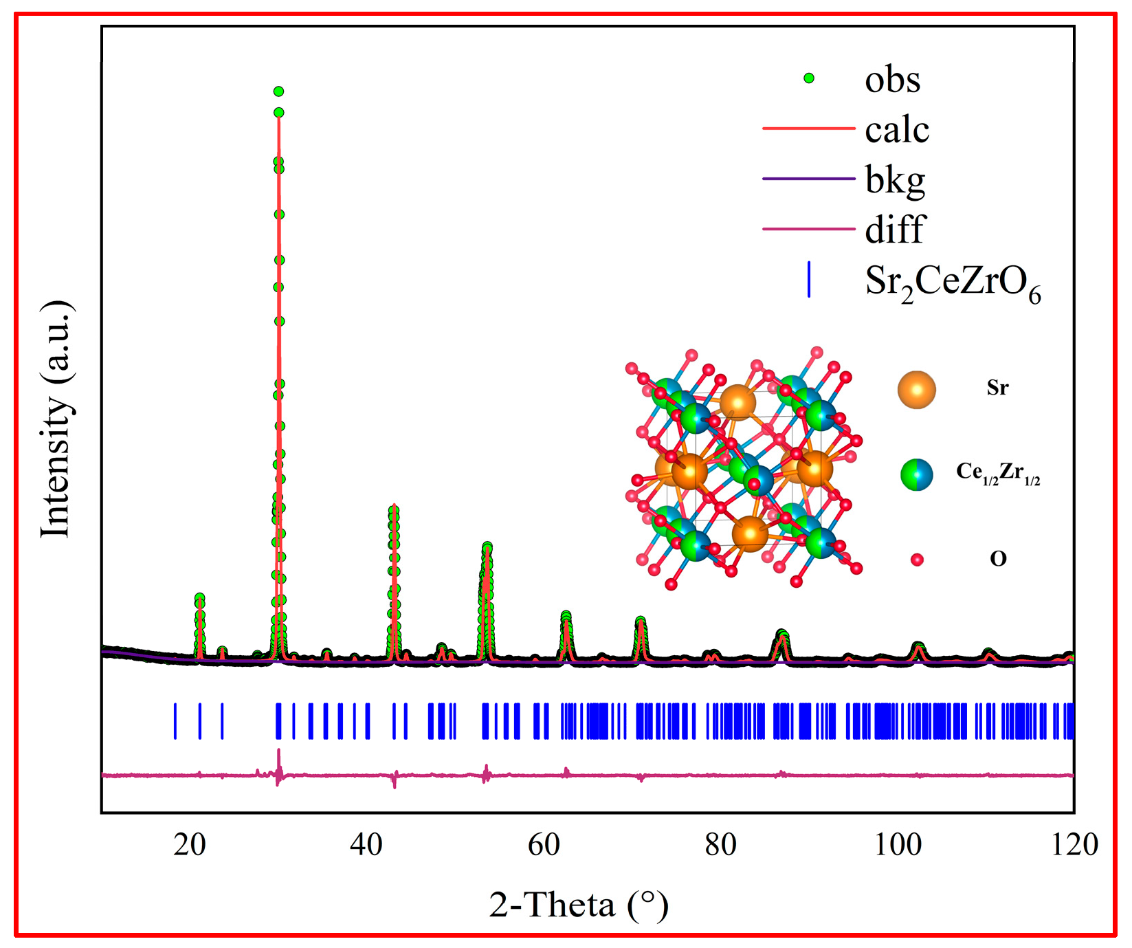
Figure 4.
(a) The SEM picture of Sr2CeZrO6 crucible surface; (b) XRD pattern of the crucible surface.
Figure 4.
(a) The SEM picture of Sr2CeZrO6 crucible surface; (b) XRD pattern of the crucible surface.
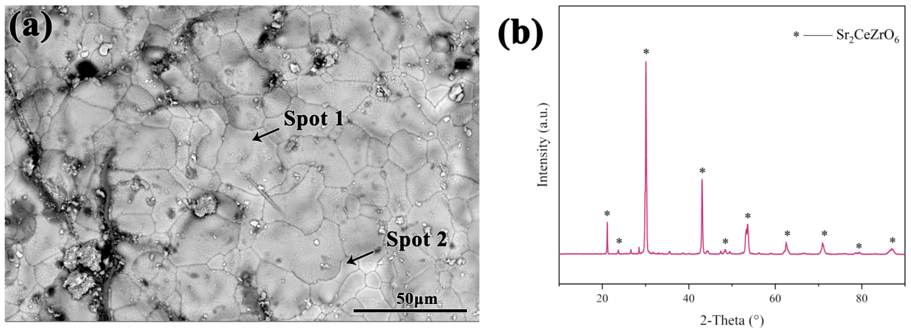
Figure 5.
The macroscopic picture of the TiAl alloy cooled in Sr2CeZrO6 crucible.
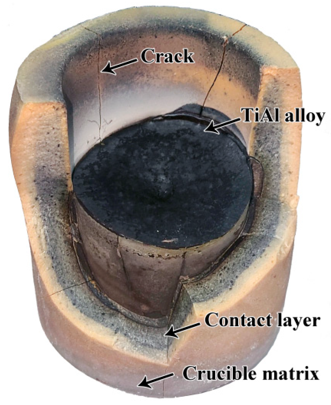
Figure 6.
Macroscopic pictures of the crucibles: (a) before the melting, (b) after the melting.

Figure 7.
(a) SEM pictures of the crucible surface before melting; (b) SEM pictures of the crucible surface after melting; (c) the magnified picture of area A in (b); (d) XRD pattern of the crucible surface after melting.
Figure 7.
(a) SEM pictures of the crucible surface before melting; (b) SEM pictures of the crucible surface after melting; (c) the magnified picture of area A in (b); (d) XRD pattern of the crucible surface after melting.
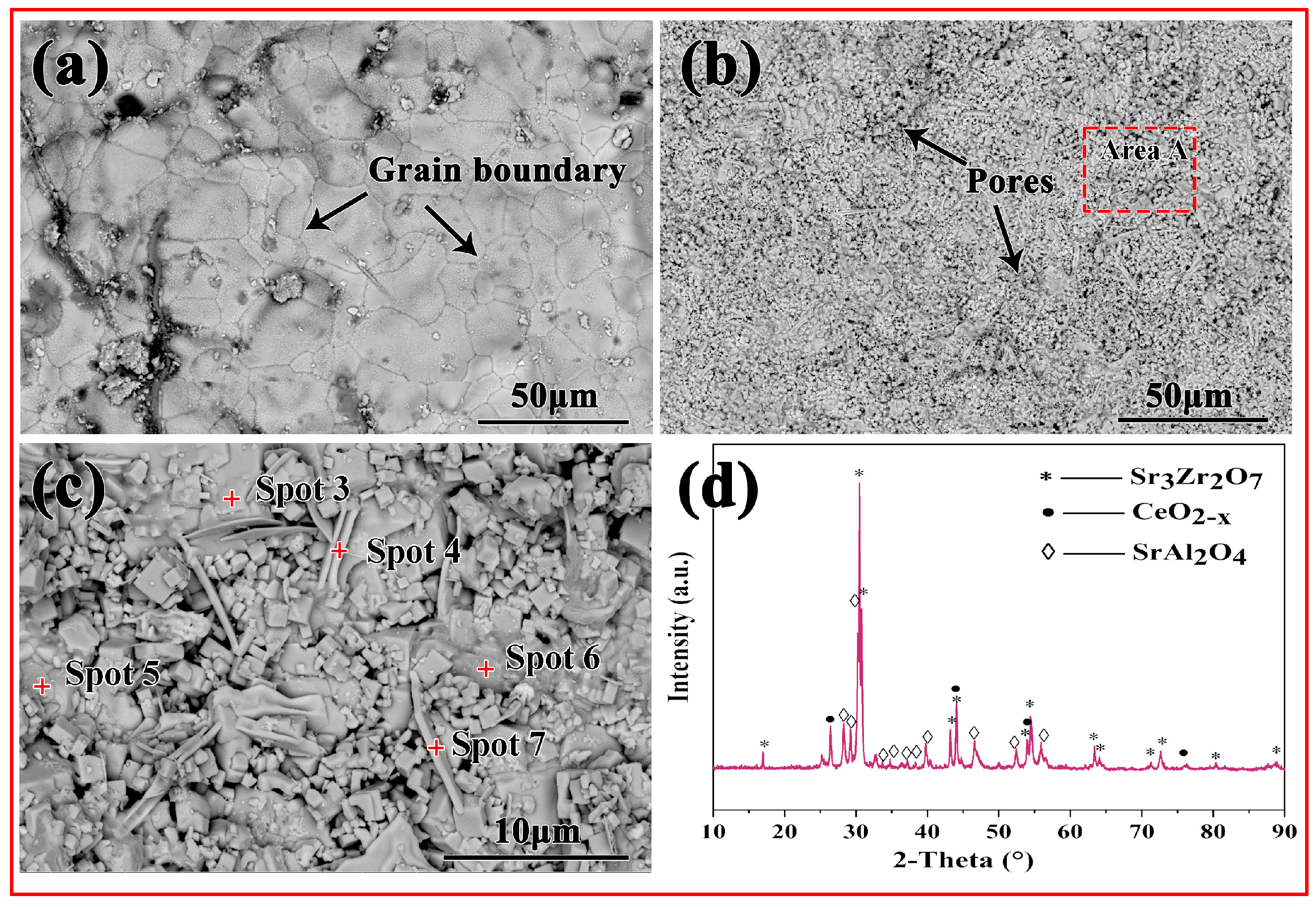
Figure 8.
Map scanning image of the sidewall of the crucible before and after melting of the alloy; (a) the cross-section of the crucibles before melting; (b) the cross-section of the crucible after melting; (c) the combination of all elements in (b); (d–i) the EDS element mapping images for Sr, Ce, Zr, O, Zr and Ti.
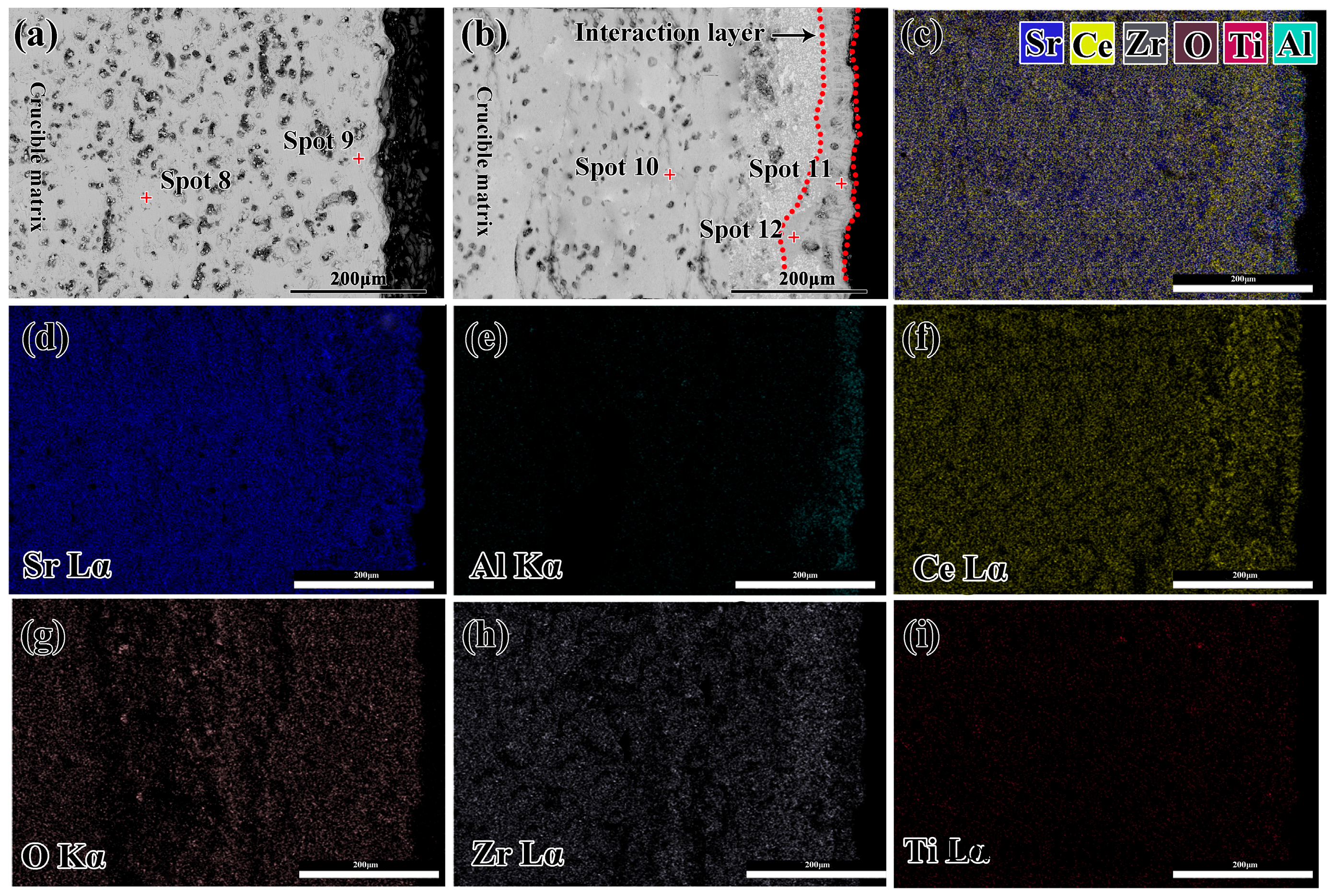
Figure 9.
High-resolution X-ray photoelectron spectroscopy (XPS) spectra of C1s, Sr3d, Ce3d and Zr3d for the interaction layer.
Figure 9.
High-resolution X-ray photoelectron spectroscopy (XPS) spectra of C1s, Sr3d, Ce3d and Zr3d for the interaction layer.
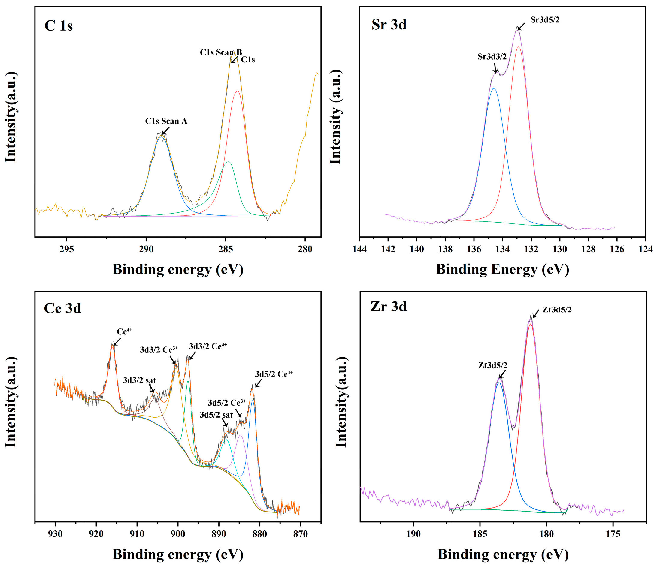
Figure 10.
Gibbs free energy for the formation of TiO2, TiO, Al2O3, CeO, ZrO2, SrO and Sr3Zr2O7.


Table 1.
Refined structural parameters of Sr2CeZrO6 by Rietveld refinement of the orthorhombic structure in the Pnma space group (No. 62).
Table 1.
Refined structural parameters of Sr2CeZrO6 by Rietveld refinement of the orthorhombic structure in the Pnma space group (No. 62).
| Atom | Wyckoff Position | x | y | z | Site Occ | Biso |
|---|---|---|---|---|---|---|
| Sr | 4c | 0.46569 | 0.25000 | −0.00795 | 1.0000 | 0.1780(7) |
| Ce | 4a | 0.00000 | 0.00000 | 0.00000 | 0.5000 | 0.00805(2) |
| Zr | 4a | 0.00000 | 0.00000 | 0.00000 | 0.5000 | 0.00810(2) |
| O | 4c | 0.02400 | 0.25000 | 0.09200 | 1.00000 | 0.03900(2) |
| O | 8d | 0.02874 | −0.04360 | 0.20730 | 1.00000 | 0.02960(3) |
Crystal structure: orthorhombic; space group (No. 62): Pnma, a = 5.9742(3) Å, b = 8.3910(5) Å, c = 5.9069(5) Å, volume of unit cell = 296.11(6) Å3; Rwp = 8.94%, GOF = 1.57, bond lengths (Å): Sr–O = 2.9809(5) Å × 12, (Sr/Zr)–O = 2.8639(3) Å × 6.
Table 2.
EDS results of spots 1 and 2 in Figure 4a.
Table 2.
EDS results of spots 1 and 2 in Figure 4a.
| Element at% | ||||
|---|---|---|---|---|
| Sr | Ce | Zr | O | |
| Spot 1 | 13.99 | 8.56 | 7.53 | 69.92 |
| Spot 2 | 17.36 | 6.97 | 7.15 | 68.52 |
Table 3.
EDS results of spots 3–7 in Figure 7.
Table 3.
EDS results of spots 3–7 in Figure 7.
| Element at% | ||||||
|---|---|---|---|---|---|---|
| Sr | Ce | Zr | O | Al | Ti | |
| Spot 3 | 19.50 | 9.30 | 1.95 | 40.12 | 26.02 | 3.11 |
| Spot 4 | 13.84 | 13.94 | 2.61 | 57.14 | 11.99 | 0.48 |
| Spot 5 | 24.34 | 1.32 | 16.07 | 55.03 | 3.12 | 0.12 |
| Spot 6 | 10.04 | 6.97 | 2.05 | 65.72 | 14.10 | 1.12 |
| Spot 7 | 11.28 | 7.81 | 2.16 | 62.75 | 13.84 | 2.16 |
Table 4.
EDS results of spots 8~12 in Figure 8.
Table 4.
EDS results of spots 8~12 in Figure 8.
| Element at% | ||||||
|---|---|---|---|---|---|---|
| Sr | Ce | Zr | O | Al | Ti | |
| Spot 8 | 19.86 | 11.31 | 10.44 | 58.39 | / | / |
| Spot 9 | 20.27 | 10.83 | 10.86 | 58.04 | / | / |
| Spot 10 | 21.61 | 10.57 | 11.49 | 56.33 | / | / |
| Spot 11 | 10.53 | 26.40 | 3.68 | 59.39 | / | / |
| Spot 12 | 20.46 | 3.94 | 14.48 | 57.02 | 4.10 | / |
Disclaimer/Publisher’s Note: The statements, opinions and data contained in all publications are solely those of the individual author(s) and contributor(s) and not of MDPI and/or the editor(s). MDPI and/or the editor(s) disclaim responsibility for any injury to people or property resulting from any ideas, methods, instructions or products referred to in the content. |
© 2023 by the authors. Licensee MDPI, Basel, Switzerland. This article is an open access article distributed under the terms and conditions of the Creative Commons Attribution (CC BY) license (https://creativecommons.org/licenses/by/4.0/).
Share and Cite
MDPI and ACS Style
Bian, F.; Cai, Z.; Liu, J.; Liu, Y.; Zhang, M.; Fu, Y.; Zhu, K.; Chen, G.; Li, C. Preparation of Sr2CeZrO6 Refractory and Its Interaction with TiAl Alloy. Materials 2023, 16, 7298. https://doi.org/10.3390/ma16237298
AMA Style
Bian F, Cai Z, Liu J, Liu Y, Zhang M, Fu Y, Zhu K, Chen G, Li C. Preparation of Sr2CeZrO6 Refractory and Its Interaction with TiAl Alloy. Materials. 2023; 16(23):7298. https://doi.org/10.3390/ma16237298
Chicago/Turabian StyleBian, Fuli, Zheyu Cai, Jian Liu, Yu Liu, Man Zhang, Yixin Fu, Kailiang Zhu, Guangyao Chen, and Chonghe Li. 2023. "Preparation of Sr2CeZrO6 Refractory and Its Interaction with TiAl Alloy" Materials 16, no. 23: 7298. https://doi.org/10.3390/ma16237298
Note that from the first issue of 2016, this journal uses article numbers instead of page numbers. See further details here.