
Morphological Evolution of TiB2 and TiAl3 in Al–Ti–B Master Alloy Using Different Ti Adding Routes


1
College of Resources, Environment and Materials, Guangxi University, Nanning 530004, China
2
Guangxi Key Laboratory of Processing for Non-ferrous Metal and Featured Materials, Guangxi University, Nanning 530004, China
3
AECC South Industry Co., Ltd., Zhuzhou 412002, China
*
Author to whom correspondence should be addressed.
Materials 2022, 15(6), 1984; https://doi.org/10.3390/ma15061984
Submission received: 8 February 2022
/
Revised: 26 February 2022
/
Accepted: 27 February 2022
/
Published: 8 March 2022
Abstract
:Three different Ti addition routes were used to prepare an Al–5Ti–B Master Alloy: the halide salt route, the Ti-sponge route, and the partial Ti-sponge route. In the halide salt route, the raw materials were Al + KBF4 + K2TiF6; K2TiF6 was completely replaced by pure titanium for the Ti-sponge route versus the halide salt route; in the partial Ti-sponge route, K2TiF6 was partially replaced by pure titanium. Here, 30% Ti-sponge or 60% Ti-sponge route means that 30% or 60% K2TiF6 was replaced by pure titanium, respectively. The above Ti addition routes have a significant influence on the growth pattern and morphological evolution of TiAl3 and TiB2, which greatly affect the refining performance of Al–Ti–B Master Alloy. When using the halide salt route, a streamlined “rich Ti, B area” exists in the aluminum melt, which is a complex compound of (Tix, Al1−x) By. The “rich Ti, B area” is essential for the nucleation and growth of TiAl3 and TiB2. Blocky TiAl3 was obtained and its average size was 4.7 μm based on the halide salt route. In the Ti-sponge route, the nucleation of TiAl3 mainly depends on the mutual diffusion of Al and Ti, and TiAlx forms around pure Ti particles, i.e., the so-called Ti–TiAlx mechanism. The average size of the blocky TiAl3 was 9.8 μm based on the Ti–TiAlx mechanism. For the partial Ti-sponge route, the “rich Ti, B area” gradually decreases with the increase in Ti powder’s contents, and large TiAl3 coexists with the small TiAl3. Compared with the Ti-sponge route, the halide salt route can form smaller TiAl3. In the Ti-sponge route, there is a small amount of “rich Ti, B area” due to the influence of the Ti–TiAlx mechanism, which does not meet the requirements of TiB2 growth. In the halide salt route, there is sufficient “rich Ti, B area”, which is conducive to the formation of TiB2. Both the crystal defects and the crowded growth environment caused by the “rich Ti, B area” are fundamental reasons for the fragility and the irregular shape of the TiB2. The refining effect of the Al–Ti–B Master Alloy prepared by the halide salt route is better than the Ti-sponge route. The refining effect of 30% Ti-sponge route is better than that of Ti-sponge route and worse than that of halide salt route.
1. Introduction
Al–Ti–B Master Alloy is an essential grain refiner and can strongly refine the microstructure and prevent the formation of coarse and equiaxed grains as well as columnar grains during the casting process of aluminum and aluminum alloy. It can also make the ingot’s microstructure become uniform, reduce segregation, and inhibit cracks. This greatly improves the mechanical and physical properties of aluminum and aluminum alloys [1,2,3,4,5]. The refinement mechanisms of Al–Ti–B Master Alloy are complicated and mainly include carbide–boride particle theory [6], peritectic reaction theory [7], peritectic hulk theory [8], and the duplex nucleation mechanism [9]. Of these, the duplex nucleation theory has attracted extensive attention [10]. The theory shows that after the Al–Ti–B was added into the aluminum melt, the melting of TiAl3 releases Ti. Ti then segregates toward TiB2 surface, which leads to an increase in the Ti concentration around TiB2 and formation of TiAl3 outside of TiB2. In this theory, the TiB2 phase plays an indirect nucleation role. The duplex nucleation mechanism indicates that a smaller size of TiB2 and TiAl3 leads to a more uniform distribution of the second phase—this in turn leads to better refining of the Al–Ti–B Master Alloy.
The preparation methods of Al–Ti–B mainly include the halide salt route [11,12], the Ti-sponge route [13], the self-propagating high-temperature synthesis method [14,15], and the reprecipitated TiB2 particles method [16]. The halide salt route and the Ti-sponge route are the primary methods for preparing. The halide salt route adds K2TiF6 and KBF4 into the aluminum melt according to the Ti/B value of the required product. The related reactions during the halide salt route are shown in Formulas (1)–(3) [17]. It is low-cost, simple production equipment and offers continuous production of stable and efficient refining effects for Al–Ti–B [13,18]. The Ti-sponge route replaces the K2TiF6 in the halide salt route with Ti powder, as shown in Formulas (4) and (5) [19]. The formation and evolution mechanisms of TiAl3 and TiB2 are different for the halide salt route and the Ti-sponge route.
Liu [20] studied the relationship between the morphology of TiAl3 and the smelting temperature for the halide salt route. Low-temperature smelting can form block-shaped TiAl3, while high-temperature smelting can quickly form rod-shaped TiAl3 crystals. Xie [21] also found that TiAl3 mainly has two morphologies: block-shaped and rod-shaped; the solute Ti grows easily around the agglomerate TiAl3, and TiB2 also has specific morphological evolution. TiB2 particles are hexagonal and independent when Al–Ti–B Master Alloy was prepared by the halide salt route [22]. The reaction temperature does not influence the morphology of TiB2. However, TiB2 particles showed different morphologies at different reaction temperatures when the Master Alloy was prepared by the Ti-sponge route [12]. The TiB2 particles are larger than 5 μm when the reaction temperature is 850 °C. When the reaction temperature reached 1200 °C, TiB2 particles gradually changed into layered stacking morphology and even a dendritic morphology. Zhang [23] confirmed by kinetic analysis that TiB2 particles are not stable in Al melt and Ti addition can suppress the dissolution of TiB2 particles. TiB2 may coarsen during the holding temperature and grow during the cooling of the melt. Wang [24] demonstrates a strong epitaxial growth of TiAl3 on the surface of TiB2 particles. Fan et al. also found that a layer of TiAl3 was formed on the surface of TiB2 and that TiAl3 can significantly improve the stability of TiB2 [25]. TiAl3 and TiB2 also interact with each other. Wang et al. also proved that TiB2 is critical to grain refinement of aluminum and aluminum alloys [26]. TiB2 particles react with aluminum slowly and release Ti into the melt. The TiAl3 particles then combine with Ti in the melt to form a dynamic Ti-rich layer on the surface of (Ti, Al) B2. This layer offers a low crystal mismatch with α-Al and promotes the nucleation of aluminum grains.
The Ti-sponge route replaces K2TiF6 in the halide salt route with Ti powder. According to the addition amount of raw materials, the amount of K2TiF6 needed, for the same content of Ti, is five times that of Ti powder. The preparation of 1 ton of Al–5Ti–B master alloy needs 0.3665 tons of mixed fluoride salt of K2TiF6 and KBF4 but only 0.1665 tons of Ti powder and KBF4. The liquid salt slags and fluoride gas produced by Ti-sponge route are much lower than that of the halide salt route. Therefore, the fluoride pollution of halide salt route is much more serious than that of the Ti-sponge route. The partial Ti-sponge route of combining the halide salt route and the Ti-sponge route may have a better refining effect and improved environmental effects. It is necessary to explore the refining effect of Al–Ti–B Master Alloy using different Ti adding routes.
The growth pattern and morphology distribution of the TiAl3 and TiB2 for different preparation processes have not been thoroughly studied. The difference between the Ti-sponge route and halide salt route is quite rarely analyzed. Here, an Al–Ti–B Master Alloy was prepared using different Ti addition routes including the halide salt route, the Ti-sponge route, and the partial Ti-sponge route. The growth pattern and morphological evolution of the TiAl3 and TiB2 were analyzed, and the refining effects using different Ti adding routes were also discussed.
2. Experimental
Table 1 shows the experimental parameters of Al–5Ti–B Master Alloy prepared by the halide salt route. Pure aluminum, KBF4, and K2TiF6 were all added at a nominal composition of the Al–5Ti–B Master Alloy (Al:Ti:B = 100:12.4:26.6, weight ratio). The dried pure aluminum was heated to 800 °C in a graphite crucible until the metal was soft-crushed. A coating agent (10.8% calcium fluoride + 72.8% magnesium chloride + 16.4% chlorinated calcium) was then covered on the surface of the aluminum melt. The slag was removed after a hexachloroethane refiner was added at 720 °C and held for 1200 S. When increasing temperature to the experimental reaction temperature (Table 1), mixed fluoride salt (KBF4 and K2TiF6 were premixed before adding) was added into the aluminum melt, stirred evenly, and held for 10–1800 S (Table 1). The melt was then poured into a preheated steel mold to obtain a cubic ingot (160 × 100 × 12 mm).
Table 2 shows the experimental parameters of Al–5Ti–B Master Alloy prepared by the partial Ti-sponge route and Ti-sponge route. Based on the halide salt route, K2TiF6 was gradually replaced by pure Ti. The Ti-sponge route means that K2TiF6 was totally replaced by pure Ti. The 30% Ti-sponge route and 60% Ti-sponge route mean that K2TiF6 was partially replaced by 30% Ti and 60% Ti, respectively.
The microstructure samples were cut from the center of the ingots at the center height, mounted, and mechanically polished. The samples were then etched using Keller’s reagent for 10 s. The microstructures were characterized using a Leica DMR research optical microscope (OM) and a SU-8020 field emission gun scanning electron microscope (FEG SEM) operating at 45 kV and a tube current of 40 μA. A D/max 2500V X-ray diffractometer equipped with Ni-filtered Cu Kα radiation source scanning over a range of 2θ = 20–80° was used to analyze TiB2 and TiAl3.
3. Results
3.1. “Rich Ti, B Area” and Morphology of TiAl3, TiB2 in Halide Salt Route
The possible reactions during the Al–Ti–B Master Alloys prepared by the halide salt route are shown in Formulas (1)–(3). These reactions are the main sources of TiAl3 and TiB2. Figure 1 shows the microstructure and composition of Al–Ti–B prepared by the halide salt route at 800 °C with different reaction times. There are obvious filamentous areas in Figure 1a. According to the EDS analysis, the filamentous areas were rich in elemental Ti but did not contain element F. This indicates that these areas should be the product areas of the fluoride salt reaction. The ratio of Ti to Al at point 2 is about 34.5%, which is nearly equal to the mass fraction of Ti in TiAl3 (about 36.96%). Considering that Al may be oxidized, point 2 should be TiAl3. Point 1 contains Ti and the energy spectrometer cannot detect the existence of B; therefore, we infer that the filamentous area is at least rich in Ti. The filamentous area gradually disappeared with longer reaction times. The filamentous area greatly reduced at 30 S (Figure 1b), and TiAl3 of thin rods or small blocks and aggregative TiB2 appeared. The filamentous area disappeared at 60 S (Figure 1c). At this point, the TiAl3 became thick rods and large blocks, and TiB2 dispersed into coarse grains. When the reaction time was extended to 600 s, the TiB2 further dispersed into fine particles (Figure 1d), thus distributing in the Al matrix. TiB2 was generated in the incipient filamentous area, which suggests that the filamentous Ti-rich area was also rich in B. Therefore, the filamentous area should be called the “rich Ti, B area”.
The XRD spectra at 800 °C for different reaction times are shown in Figure 2 to further confirm the “rich Ti, B area”. The main phases of all samples were Al, TiAl3, and TiB2, and no prominent excess peaks were observed. The intensity of the TiAl3 peak is basically the same from 10 S to 1800 S, which indicates that TiAl3 generated at the initial stage of the halide salt reaction. The TiB2 peak obviously changed from weak to strong. There is no TiB2 peak in the XRD pattern at 10 S and a weak TiB2 peak appears at 15 S, thus indicating that the formation of TiB2 is slower than that of TiAl3 or it generates too little to detect in the early stage. The TiB2 and AlB2 have a similar crystal structure, and thus, diffraction peaks may be broadened or separated in XRD diffraction. If the value of Ti/B is greater than 2.2, then excess B will form AlB2 [27]. Therefore, the peaks in the two square frames in Area1 were considered to be AlB2, which are very close to the strong peak of TiB2. A small amount of AlB2 also exists in the early stage of the reaction. Some studies have reported the nonhomogenous distribution of solutes B and Ti close to the salts/Al melt interface during the reaction of the fluoride salts and Al melt. These form unstable AlB2. The AlB2 transforms to TiB2 via diffusion of solutes Ti and B in the aluminum melt in the subsequent holding temperature process [28,29]. The essence of filamentous areas (Figure 1a) is a complex compound (Tix, Al1−x)By; this area was called the “rich Ti, B area”. In the early stage of the halide salt reaction, the streamlined “rich Ti, B area” existed in the aluminum melt (Figure 1a). The formation of TiAl3 was very fast (less than 10 S). The “rich Ti, B area” was the birthplace of the nucleation and growth of initial TiAl3 and TiB2 for the halide salt route.
Figure 3 clearly shows the morphology of the TiB2 in the Al–Ti–B Master Alloy prepared by the halide salt route at 800 °C for 300 S. The white shadow on the particle’s edge shows that TiB2 is hexagonal with a certain thickness. The maximum section size of these hexagons is 0.5–1.0 μm. In the statistics of T.E. Quested [28], the size of TiB2 particles in conventional Al–Ti–B Master Alloy is about 5 μm, and the size of most TiB2 is 0.5–1.5 μm. Figure 3b shows the irregular TiB2; they may be the side cuts of the hexagonal TiB2; however, the mutual “crashing” during fragile TiB2′s growth also may lead to the forming of the irregular shape (Figure 3c).
Figure 4 shows the morphology of TiAl3 prepared by the halide salt route at 800 °C for 15 S, 30 S, or 60 S. At 800 °C for 15 S, the TiAl3 was granular or elongated rod-shaped. When the reaction time was extended to 30 S, the strip phase became a thick rod. TiAl3 was blocky when the reaction time was 60 S.
3.2. Morphology of TiAl3, TiB2 in the Ti-Sponge and Partial Ti-Sponge Route
The reactions of preparing Al–Ti–B Master Alloy by the Ti-sponge route are shown in Formulas (4) and (5). Reaction (4) occurred spontaneously at the temperature range of 800–900 °C [19]. The mass ratio of Ti to B is 4.43:1 in reaction (4). The mass ratio of Ti/B added to the reaction is 5:1. Therefore, reaction (5) also occurred. Figure 5 shows the X ray diffraction pattern of the Al–Ti–B Master Alloy prepared by the Ti-sponge route with reaction times of 15 S, 300 S, and 1800 S. The diffraction peaks of the TiB2 were observed at 15 S. AlB2 and TiB2 existed in the matrix simultaneously at 15 S (consistent with Formula (5)) for TiB2 diffraction peaks broadening.
The microstructure and EDS of Al–Ti–B Master Alloys prepared by the Ti-sponge route and partial Ti-sponge route at 800 °C for different times are shown in Figure 6 and Figure 7. Figure 6a1,a2 shows different parts of the same sample. Owing to the short reaction time of 15 S, some Ti powders did not have enough time to diffuse. Therefore, the irregular white blocky TiAl3 was observed in Figure 6a1. Other Ti powders are relatively dispersed to form fine, rod-shaped TiAl3 (Figure 6a2). At a reaction time of 300 S, the whole block dispersed into small, irregular pieces (Figure 6b). The original fine, rod-shaped structure disappeared. The energy spectrum analysis indicated the white phase in Figure 6b should be pure Ti, and the surrounding gray phase should be TiAlx. The concentration of Al in the gray phase decreased gradually from inside to outside while Ti increased. The value of Ti/Al at point 3 was closer to 36.96%, which is TiAl3.
There are both blocky and rod-shaped TiAl3 in Figure 8. Further, it was found that TiB2 was embedded in blocky TiAl3 (Figure 7b). The hexagonal holes appeared in the rod-shaped TiAl3 and were eroded by pure Al (Figure 7a). If B was added into the Al–Ti alloy melt containing TiAl3, then B could form TiB2 on the TiAl3 and cause the TiAl3 to break or even dissolve [29]. The resulting TiB2 will be agglomerated between the TiAl3 and Al matrix. The reaction equation is as follows:
3.3. Refining Effect of Al–Ti–B Master Alloy
The Al–Ti–B Master Alloy obtained at 800 °C for 1800 S using different routes was used to refine pure aluminum ingot; the refined microstructure is shown in Figure 8. The average grain sizes of pure aluminum ingot refined by halide salt route, 30% Ti-sponge route, and Ti-sponge route are 98.3 μm, 105.4 μm, and 111.8 μm, respectively. The refining effect of 30% Ti-sponge route is better than that of Ti-sponge route and worse than that of halide salt route.
The size of TiAl3 obtained using the Ti-sponge route was larger than that using the halide salt route; they are 9.83 μm (Figure 6) and 4.7 μm (Figure 4), respectively. In the 30% Ti-sponge or 60% Ti-sponge route, the large-sized granular TiAl3 was coexistent with the small-sized TiAl3 (Figure 4). The size of TiB2 particles is about 5 μm, and the size of most TiB2 is 0.5–1.5 μm (Figure 3). The refining effect of Al–Ti–B Master Alloy is related to the size and distribution of TiAl3 and TiB2. A finer size and more uniform distribution of TiAl3 and TiB2 causes the Al–Ti–B Master Alloy to have a better grain-refining effect.
4. Discussion
4.1. Nucleation and Growth of TiAl3 and TiB2 in Different Ti Adding Routes—The Ti–TiAlx Mechanism
The nucleation of TiAl3 mainly depends on the mutual diffusion of Al and Ti for the Ti-sponge route. This diffusion process makes TiAlx form around the pure Ti particles first, as shown in Figure 6b. As diffusion progresses, the external TiAlx is separated into single TiAl3, but the concentration of internal Ti remains high (Figure 6a1). Finally, the TiAlx completely converted into separated TiAl3 after 300 S reaction at 800 °C (Figure 6b). This mechanism is called the Ti–TiAlx mechanism for the Ti-sponge route, as shown in Figure 9. Sunda [30] proposed that Ti–Al’s interdiffusion coefficient (D) is a function of composition and temperature; D increases with increasing temperature when the composition is constant. The diffusion activation energy of aluminum (Q) is different in different phases, but Q is substantially constant and independent of the concentration. We have the following order: Q[TiAl3] > Q[TiAl] > Q[α-Ti(Al)] > Q[β-Ti(Al)]. Obviously, the diffusion coefficient of Al in Ti3Al is smaller than that in Ti particles. Therefore, Al enriched on the Ti particle’s surface passed through the TiAl3 layer (Figure 9) resulting in a high concentration of Al surrounding the surface of the Ti particles. Thus, TiAlx is constantly formed and eventually converted into separate TiAl3.
The nucleation mechanism of the rod-shaped TiAl3 (Figure 6a2) is different from the Ti–TiAlx mechanism. The atomic ratio of Ti to KBF4 is 1:1 in reaction (4). Actually, the ratio of Ti to KBF4 is about 1.13:1 in this experiment so that KBF4 can react completely. The rod-shaped TiAl3 comes from reaction (4) and is easy to dissolve versus blocky TiAl3; therefore, it almost disappeared after 300 S of reaction (4), as shown in Figure 6b. For the Ti-sponge route, Ti is involved in the transition of Ti–TiAlx to produce TiAl3, which leads to the deficiency of Ti and excess of B. The B can form TiB2 on the TiAl3 and cause TiAl3 to break and be dissolved. The long, rod-shaped TiAl3 is more easily dissolved than the block-shaped TiAl3 [31]. Therefore, in the Ti-sponge route, the initial formation of the rod-shaped TiAl3 does not stay easily in the melt, which is different from the characteristic of the halide salt route. However, there is still a rod-shaped TiAl3 in the microstructure of the Al–Ti–B Master Alloy prepared by the 30% Ti-sponge route with the reaction temperature of 800 °C for 900 S. The total amount of Ti is constant, and with less free Ti content, there is less of a Ti–TiAlx mechanism. When there is less excess B, some of the rod-shaped TiAl3 are retained and less Ti is consumed in the melt.
Section 3.1 shows that the “rich Ti, B area” is the birthplace of the nucleation and growth of initial TiAl3 and TiB2 for the halide salt route. Similarly, the “rich Ti, B area” are also found in the partial Ti-sponge route as shown in Figure 10b. The “rich Ti, B area” gradually decreased with increasing Ti powder content; only a small amount of filamentous and small strip regions were formed in the Ti-sponge route. In Ti-sponge route, a lot of Ti powder is directly involved in the formation of TiAl3 by the Ti–TiAlx mechanism. During the nucleation and growth of TiAl3, the blocky Ti powder seriously hindered the diffusion of Ti into the Al melt, thus resulting in insufficient Ti in the melt. The insufficient diffusion of Ti also severely reduced the amount of Ti involved in the reaction (4), thus reducing the “rich Ti, B area” in the melt.
The Ti addition routes have greatly influenced the morphology and size of TiAl3. The size of TiAl3 formed based on the Ti–TiAlx mechanism in the Ti-sponge route is coarse. Ti and Al diffused mutually in the TiAlx around the Ti particles, and the outer TiAl3 is mainly separated into small blocks. The “rich Ti, B area” in the Ti-sponge route under the influence of the Ti–TiAlx mechanism is a small amount that cannot meet the TiB2 growth well. Due to the Ti–TiAlx mechanism, the diffusion efficiency of Ti in Ti-sponge route is much lower than halide salt route. TiAl3 formed based on the chemical reaction (4) is long and rod-shaped. The long, rod-shaped TiAl3 cannot exist stably in the melt due to the excess B and lack of Ti in the pre-reaction melt. Therefore, it does not appear in the final microstructure.
4.2. Evolution Mechanism of TiB2 with Irregular Polygon
In addition to reaction (1), the following reaction may produce TiB2 when the Al–Ti–B Master Alloy is prepared by the halide salt route [32]:
Here, TiB2 is nucleated by the fluorination reaction and grown in the rich Ti and B area based on the above two reactions. Figure 11 shows the microstructure of the TiB2 when the mixed fluoride salt is added into the aluminum melt at 800 °C for 10 S–600 S using the halide salt route.
The TiB2 was an irregular small particle at the initial stage of the reaction (10 S and 15 S). Regular hexagonal TiB2 particles appeared with longer reaction times to 20 S and 30 S, and the size of TiB2 was about 0.5 μm. At 60 S, the size of TiB2 particle continued to increase. At 5 min, some TiB2 collided together and cracks appeared along the junction of particles. At a reaction time of 10 min, the size of TiB2 particles reached 1.5 μm and there were a lot of lug boss’ around the TiB2 particles. According to the reaction (7), the filamentous AlB2 (corresponding to (Tix, Al1−x)By in Figure 1a) was more likely to be destroyed when it was transformed into TiB2 [33]. Therefore, TiB2 was more easily crushed with increasing reaction time.
The crushing of TiB2 is related to the crystal structure. Figure 12a,c represent the crystal growth model of TiB2 [34]. TiB2 belongs to hexagonal system (the lattice parameters a = 0.3030 nm, c = 0.3232 nm, c/a = 1.0818). The growth direction extends longitudinally in the direction of <0001> or extends laterally in the direction of <100>. The growth rate is the slowest because the {0001} surface has the highest atomic density and the lowest surface energy. Thus, the longitudinal growth rate of TiB2 is lower than the lateral expansion speed. The lug boss in <0001> direction and the projecting lug in <100> direction were also observed, as shown in Figure 12b,d,e.
In the nucleation of TiB2, the generation and expansion mechanism of lug boss plays a significant role. The contents of Ti and B in the “rich Ti, B area” are sufficient, and the TiB2 (0001) surface is small and provides favorable conditions for the formation of lug boss. When the lug boss is generated in the [1] direction, the lug boss rapidly expands the entire (0001) plane, and the thickness and size of the TiB2 quickly increase. The nucleation of TiB2 is similar to the layered stacking pattern according to the above mechanism (Figure 12a,b). There may be parallel surface defects between the new layer formed by the lug boss and the original layer. The formation and expansion mechanism of the projecting lug play a significant role during the TiB2 growth. The Ti and B in the “rich Ti, B area” were partially consumed at TiB2 growth stage. The growth of the {0001} plane requires larger surface energy, which makes the formation and expansion of the lug boss difficult. Therefore, the thickness of the TiB2 does not change. The growth of TiB2 is the lug generation and expansion in the direction <100>.
Figure 12c–e show that many lugs in the {1100} plane are prone to producing crystal defects during simultaneous growth. When the two lugs grow in parallel, there may be a planar defect parallel to the {1100} plane between the upper and lower lugs. When the two lugs grow side by side, between the left and right lugs, it is possible to form a planar defect perpendicular to the {1100} plane. The {1100} plane is not flat when the lug stops the growth eventually due to the lack of Ti and B.
The crushing of the TiB2 is also related to the growth environment. Figure 13 shows the microstructure of the “rich Ti, B area” for the halide salt route at 800 °C for 60 S. The TiB2 was rich in “rich Ti, B area” and many TiB2 particles were clustered together during the growth process. This aggregation phenomenon can also crush TiB2. It is difficult to ensure uniform growth in all directions; thus, TiB2 has an irregular morphology.
5. Conclusions
- (1)
- The fluorine salt reaction occurred very fast when Al–Ti–B was prepared by the halide salt route (<10 S). A streamlined “rich Ti, B area” exists in the aluminum melt in the initial stage of the reaction ((800 °C, <30 S). This is a complex compound of (Tix, Al1−x) By. The “rich Ti, B area” is essential for the nucleation and growth of TiAl3 and TiB2.
- (2)
- The Ti addition route greatly influences the morphology of TiAl3. The formation of TiAl3 using the Ti-sponge route is based on the Ti–TiAlx mechanism. The nucleation of TiAl3 mainly depends on the mutual diffusion of Al and Ti powder, and TiAlx formed around the Ti particles. The TiAl3 formed based on the Ti–TiAlx mechanism is mainly block-shaped and the average size is 9.83 μm. In the halide salt route, TiAl3 formation is based on the reaction of Ti powder and KBF4 to form a rod-shaped TiAl3. The long, rod-shaped TiAl3 disappeared due to excess B and a lack of Ti in the aluminum melt. Finally, small blocks of TiAl3 formed with an average size of 4.7 μm.
- (3)
- TiB2 particles showed different morphologies at different reaction times when the Master Alloy was prepared by the halide salt route. The TiB2 was an irregular and small particle at the initial stage of the reaction (10 S and 15 S). Regular hexagonal TiB2 particles appeared as the reaction time increased to 20 S and 30 S. The size of TiB2 was about 0.5 μm. The size of TiB2 particle continued to increase at 60 S. Some TiB2 collided together at 5 min. Both the crystal defects and the crowded growth environment caused by the “rich Ti, B area” are the fundamental reasons for the fragility and irregular shape of the TiB2.
Author Contributions
Conceptualization, Y.Z., W.Y. and Z.L.; methodology, Z.L., L.M., Z.H. and W.Y.; formal analysis, Y.Z., Z.L. and L.M.; writing—original draft preparation, Z.L. and Y.Z.; paper revision, Y.Z. and Z.L.; project administration, Y.Z. and Z.H. All authors have read and agreed to the published version of the manuscript.
Funding
This research was supported by Development of Science and Technology of Nanning, grant number 20201045, Innovation Drive Development Foundation of Guangxi, grant number GKAA17202011, GKZ14122001-3 and Guangxi Key Laboratory Project for Processing Non-ferrous Metals and Characteristic Materials, grant number GXYSSF1809.
Acknowledgments
The authors gratefully acknowledge the equipment managers of Guangxi Key Laboratory Project for Processing Non-ferrous Metals and Characteristic Materials.
Conflicts of Interest
The authors declare no conflict of interest.
References
- Li, J.H.; Hage, F.S.; Ramasse, Q.M.; Schumacher, P. The nucleation sequence of α-Al on TiB2 particles in Al-Cu alloys. Acta Mater. 2021, 206, 116652. [Google Scholar] [CrossRef]
- Fan, Z.; Gao, F.; Jiang, B.; Que, Z. Impeding Nucleation for More Significant Grain Refinement. Sci. Rep. 2020, 10, 9448. [Google Scholar] [CrossRef] [PubMed]
- Li, Y.; Hu, B.; Liu, B.; Nie, A.; Li, Q. Insight into Si poisoning on grain refinement of Al-Si/Al-5Ti-B system. Acta Mater. 2020, 187, 51–65. [Google Scholar] [CrossRef]
- Ding, W.W.; Zhao, X.Y.; Chen, T.L.; Zhang, H.X.; Liu, X.X.; Cheng, Y.; Lei, D.K. Effect of rare earth Y and Al-Ti-B master alloy on the microstructure and mechanical properties of 6063 aluminum alloy. J. Alloys Compd. 2020, 830, 154685. [Google Scholar] [CrossRef]
- Peeratatsuwan, C.; Chowwanonthapunya, T. Investigation of the grain refining performance of Al-5Ti-1B master alloy on the recycling process of A356 alloy. Materialwiss. Werkst. 2020, 51, 1346–1352. [Google Scholar] [CrossRef]
- Mi, L.; Wang, J.J.; Hu, Z.L. The Research Progress of TiB2 Impacts on the Refining Effect of Al-Ti-B Master Alloy. Appl. Mech. Mater. 2014, 574, 391–395. [Google Scholar] [CrossRef]
- Crossley, F.A.; Mondolfo, L.F. Mechanism of Grain Refinement in Aluminum Alloys. JOM 1951, 191, 1143–1148. [Google Scholar] [CrossRef]
- Backerud, L.; Gustafson, P.; Johnsson, M. Grain Refining Mechanisms in Aluminum as a Result of Additions of Titanium and Boron. Aluminium 1991, 67, 780. [Google Scholar]
- Wang, X.; Han, Q. Grain Refinement Mechanism of Aluminum by Al-Ti-B Master Alloys. In Light Metals; Springer: Cham, Switzerland, 2016. [Google Scholar]
- Kashyap, K.T.; Chandrashekar, T. Effects and mechanisms of grain refinement in aluminium alloys. Bull. Mater. Sci. 2001, 24, 345–353. [Google Scholar] [CrossRef] [Green Version]
- Zhang, L.; Jiang, H.; Zhao, J.; He, J. Microstructure and grain refining efficiency of Al-5Ti-1B master alloys prepared by halide salt route. J. Mater. Process. Technol. 2017, 246, 205–210. [Google Scholar] [CrossRef]
- Yi, H.; Ma, N.; Zhang, Y.; Li, X.; Wang, H. Effective elastic moduli of Al-Si composites reinforced in situ with TiB2 particles. Scr. Mater. 2006, 54, 1093–1097. [Google Scholar] [CrossRef]
- Birol, Y. Production of Al-Ti-B master alloys from Ti sponge and KBF4. J. Alloys Compd. 2007, 440, 108–112. [Google Scholar] [CrossRef]
- Pourbagheri, H.; Aghajani, H. SHS-Produced Al-Ti-B Master Alloys: Performance in Commercial Al Alloy. Int. J. Self-Propagating High-Temp. Synth. 2018, 27, 245–254. [Google Scholar] [CrossRef]
- Chai, L.; Wang, H.; Chen, Z.; Cui, Y. Evaluation of Microstructure and Refining Effect of Al-TiB2 and Al-5Ti-1B Grain Refiners. Phys. Eng. Met. Mater. 2019, 217, 295–306. [Google Scholar]
- He, M.; Zhang, L.; Jiang, H.; He, J.; Zhao, J. Improved grain refinement in aluminium alloys by re-precipitated TiB2 particles. Mater. Lett. 2022, 312, 131657. [Google Scholar]
- Bian, X.F. Cast Metal Genetics; Shandong Science and Technology Press: Jinan, China, 1999. [Google Scholar]
- Auradi, V.; Kori, S.A. Preparation and Characterization of Al-1Ti-3B Master Alloys by Salt Route and Evaluation of their Grain Refining Performance on Al-7Si Alloys. Mater. Sci. Forum 2014, 790–791, 173–178. [Google Scholar] [CrossRef]
- Lan, Y.; Zhang, J.; Zhu, Z.; Guo, P. Melt reaction mechanism of Al-Ti-B system. Spec. Cast. Nonferrous Alloys 2006, 26, 12–14. [Google Scholar]
- Liu, X.F.; Bian, X.F.; Yang, Y. The formation law of TiAl3 morphologies in AlTi5B master alloy. Spec. Cast. Nonferrous Alloys 1997, 5, 4–6. [Google Scholar]
- Xie, H.; Lv, J. Precipation of TiAl3 in remelting Al-5Ti-1B and the grain refinement of 7050 alloy. Mater. Res. Express 2021, 8, 066513. [Google Scholar] [CrossRef]
- Li, P.; Li, Y.; Nie, J.; Liu, X. Influence of forming process on three-dimensional morphology of TiB2 particles in Al-Ti-B alloys. Trans. Nonferrous Met. Soc. China 2012, 22, 564–570. [Google Scholar] [CrossRef]
- Zhang, L.L.; Jiang, H.X.; Jie, H.E.; Zhao, J.Z. Kinetic behaviour of TiB2 particles in Al melt and their effect on grain refinement of aluminium alloys. Trans. Nonferrous Met. Soc. China 2020, 30, 2035–2044. [Google Scholar] [CrossRef]
- Wang, X.; Song, J.; Vian, W.; Ma, H.; Han, Q. The Interface of TiB2 and Al3Ti in Molten Aluminum. Metall. Mater. Trans. B 2016, 47, 3285. [Google Scholar] [CrossRef]
- Fan, Z.; Wang, Y.; Zhang, Y.; Qin, T.; Zhou, X.R.; Thompson, G.E.; Pennycook, T.; Hashimoto, T. Grain refining mechanism in the Al/Al-Ti-B system. Acta Mater. 2015, 84, 292–304. [Google Scholar] [CrossRef]
- Wang, X.; Liu, Z.; Dai, W.; Han, Q. On the Understanding of Aluminum Grain Refinement by Al-Ti-B Type Master Alloys. Metall. Mater. Trans. B 2015, 46, 1620–1625. [Google Scholar] [CrossRef]
- Hong, M.A.; Jian, L.I.; Zhang, B.; Fang, H. Analysis of microstructures in Al-Ti-B alloy. Chin. J. Nonferrous Met. 2001, 5, 801–805. [Google Scholar]
- Quested, T.E.; Greer, A.L. The effect of the size distribution of inoculant particles on as-cast grain size in aluminium alloys. Acta Mater. 2004, 52, 3859–3868. [Google Scholar] [CrossRef]
- Emamy, M.; Mahta, M.; Rasizadeh, J. Formation of TiB2 particles during dissolution of TiAl3 in Al-TiB2 metal matrix composite using an in situ technique. Compos. Sci. Technol. 2006, 66, 1063–1066. [Google Scholar] [CrossRef]
- Sun, D.; Wang, L. Calculation of Interdiffusion Coefficient between a Ti Substrate and an A1 Film. Shanghai Nonferrous Met. 1992, 2, 1–5. [Google Scholar]
- Hou, B. Pay Attention to Some Problem in Using Al-Ti-B Refiner during Aluminium Continuous Cast-rolling Process. Light Alloy Fabr. Technol. 2004, 32, 14–17. [Google Scholar]
- Ramesh, C.S.; Pramod, S.; Keshavamurthy, R. A study on microstructure and mechanical properties of Al 6061-TiB2 in-situ composites. Mater. Sci. Eng. A 2011, 528, 4125–4132. [Google Scholar] [CrossRef]
- Fjellstedt, J.; Jarfors, A.E.W. On the precipitation of TiB2 in aluminum melts from the reaction with KBF4 and K2TiF6. Mater. Sci. Eng. A 2005, 413–414, 527–532. [Google Scholar] [CrossRef]
- Zhang, H.; Gao, W.L.; Zhang, E.L.; Zeng, S.Y. Morphology evolution and growth mechanism of TiB2 in Ti-54Al-xB alloys. Acta Metall. Sin.-Chin. Ed. 2002, 38, 699–702. [Google Scholar]
Figure 1.
Microstructure and EDS of Al–Ti–B Master Alloy prepared by the halide salt route with different reaction times at 800 °C: (a) 10 S; (b) 30 S; (c) 60 S; (d) 600 S.
Figure 1.
Microstructure and EDS of Al–Ti–B Master Alloy prepared by the halide salt route with different reaction times at 800 °C: (a) 10 S; (b) 30 S; (c) 60 S; (d) 600 S.
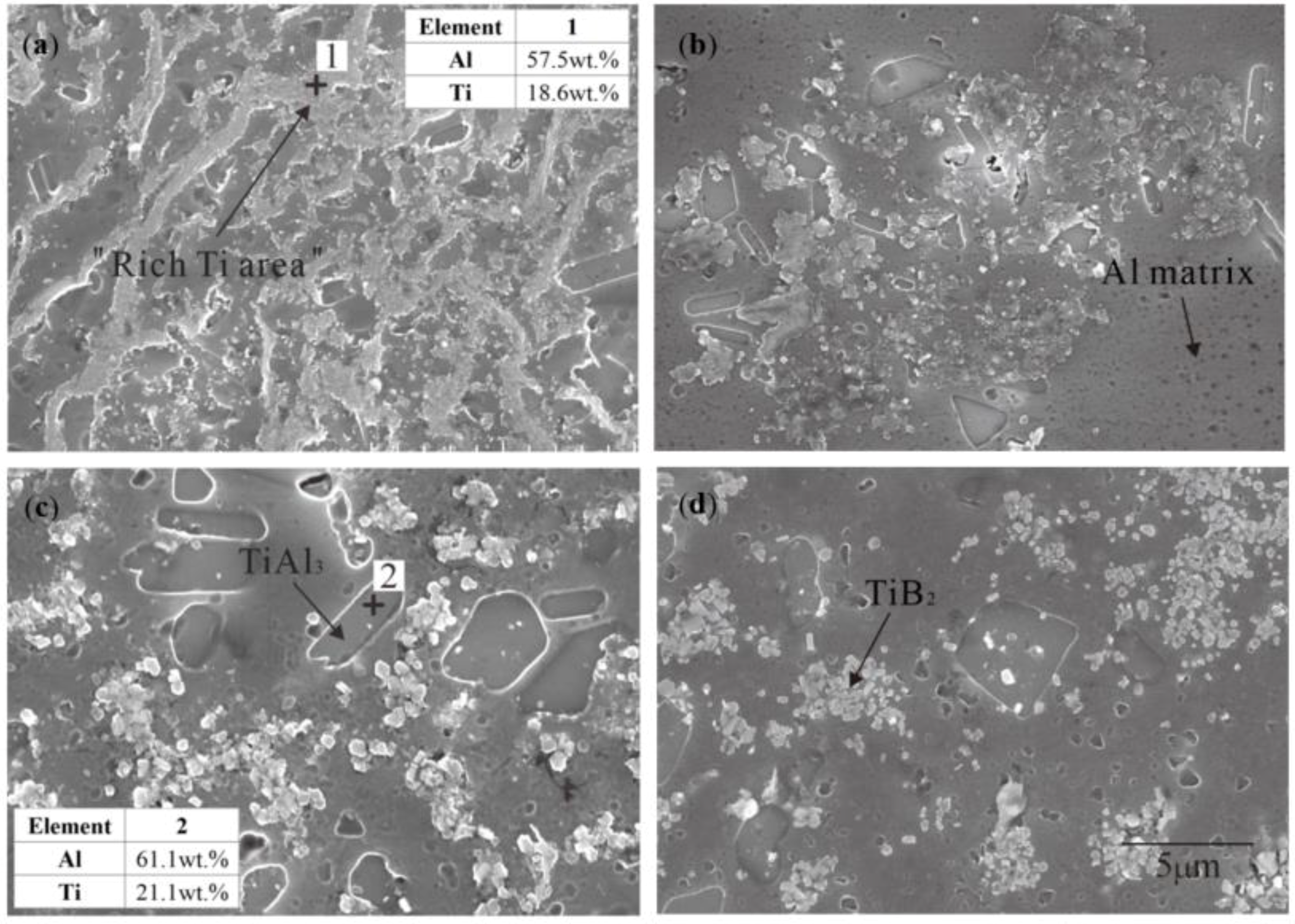
Figure 2.
XRD pattern of Al–Ti–B Master Alloy prepared by the halide salt route at 800 °C for different reaction times.
Figure 2.
XRD pattern of Al–Ti–B Master Alloy prepared by the halide salt route at 800 °C for different reaction times.

Figure 3.
Morphology of TiB2 in the Al–Ti–B Master Alloy prepared by the halide salt route at 800 °C for 600 s: (a) hexagonal TiB2; (b) irregular polygon TiB2; (c) mutual ”crashing” of fragile TiB2.
Figure 3.
Morphology of TiB2 in the Al–Ti–B Master Alloy prepared by the halide salt route at 800 °C for 600 s: (a) hexagonal TiB2; (b) irregular polygon TiB2; (c) mutual ”crashing” of fragile TiB2.
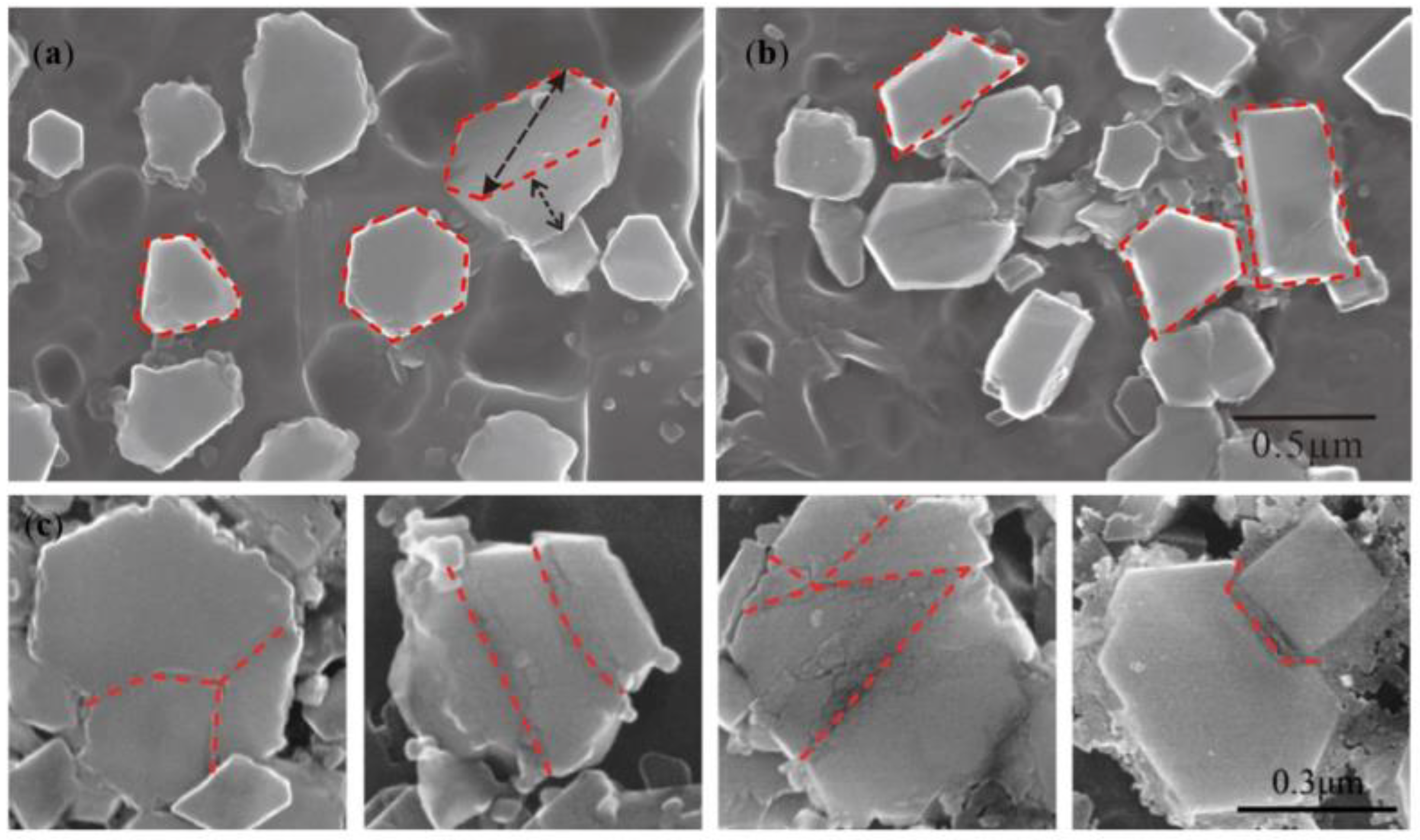
Figure 4.
Morphology of TiAl3 in the Al–Ti–B Master Alloy prepared by the halide salt route after different reaction times at 800 °C: (a) 15 S; (b) 30 S; (c) 60 S.
Figure 4.
Morphology of TiAl3 in the Al–Ti–B Master Alloy prepared by the halide salt route after different reaction times at 800 °C: (a) 15 S; (b) 30 S; (c) 60 S.

Figure 5.
XRD analysis of Al–Ti–B Master Alloy prepared by Ti-sponge route at 800 °C with different reaction times.
Figure 5.
XRD analysis of Al–Ti–B Master Alloy prepared by Ti-sponge route at 800 °C with different reaction times.
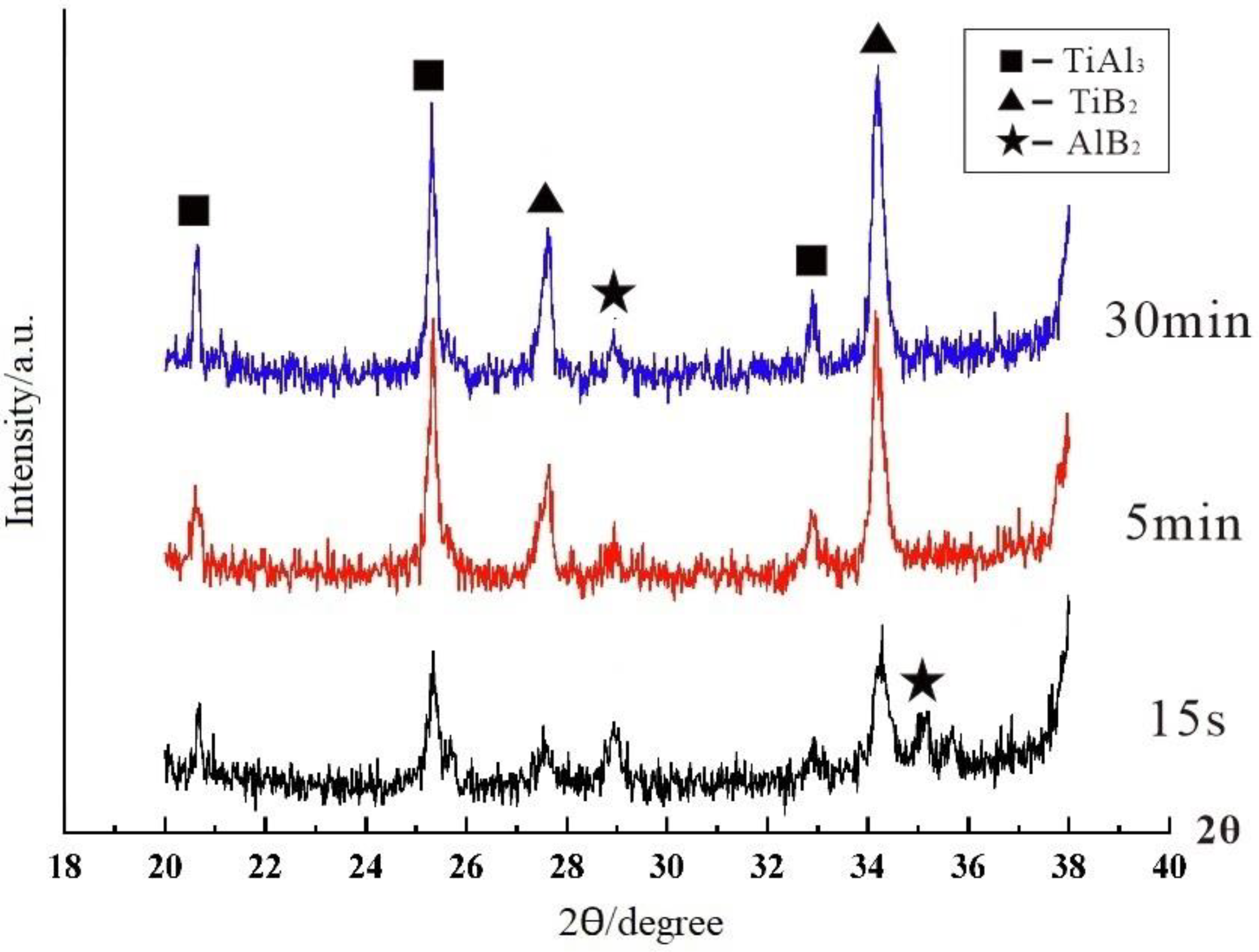
Figure 6.
The microstructure and EDS of Al–Ti–B Master Alloy prepared by the Ti-sponge route at 800 °C: (a1) 15 S reaction time—irregular blocky TiAl3; (a2) 15 S reaction time—fine, rod-shaped TiAl3; (b) 300 S reaction time.
Figure 6.
The microstructure and EDS of Al–Ti–B Master Alloy prepared by the Ti-sponge route at 800 °C: (a1) 15 S reaction time—irregular blocky TiAl3; (a2) 15 S reaction time—fine, rod-shaped TiAl3; (b) 300 S reaction time.
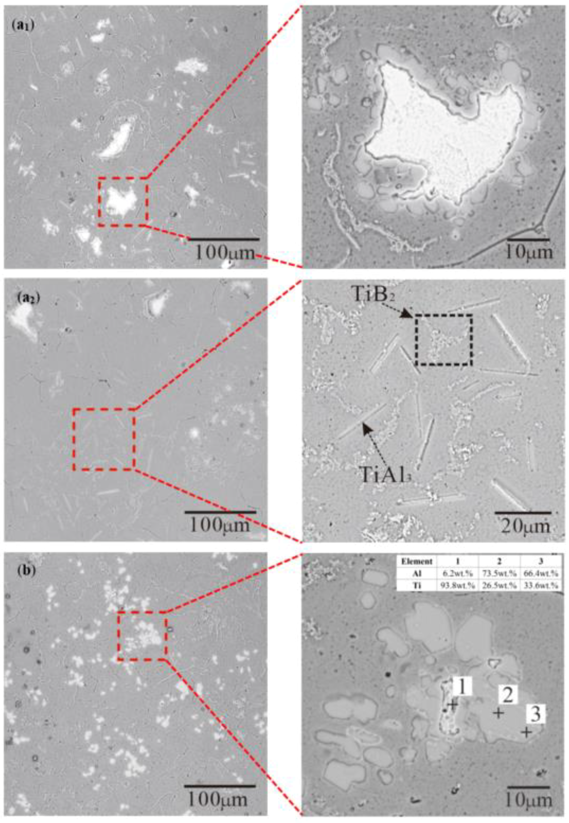
Figure 7.
Microstructure of Al–Ti–B Master Alloy prepared by partial Ti-sponge route at 800 for 300 S: (a) 30% Ti-sponge route; (b) 60% Ti-sponge route.
Figure 7.
Microstructure of Al–Ti–B Master Alloy prepared by partial Ti-sponge route at 800 for 300 S: (a) 30% Ti-sponge route; (b) 60% Ti-sponge route.
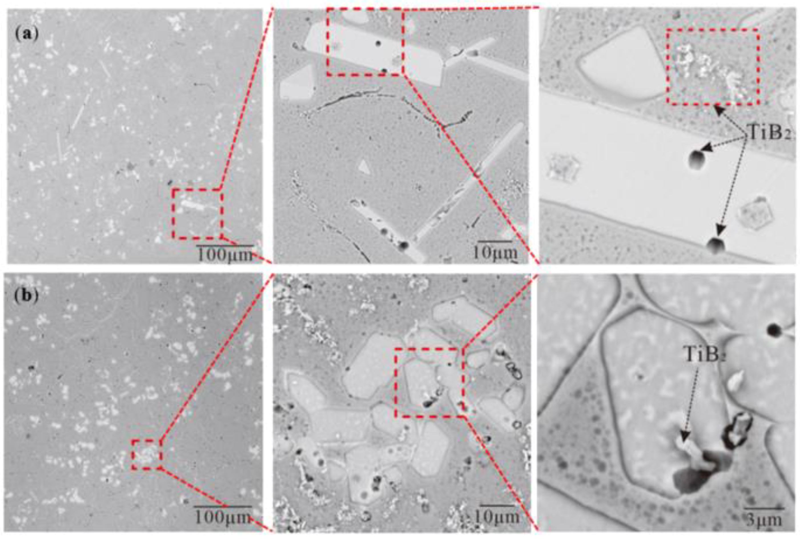
Figure 8.
The refining effect of different Al–Ti–B Master Alloy on pure aluminum: (a) Pure aluminum; (b) 30% Ti-sponge route; (c) Ti-sponge route; (d) halide salt route.
Figure 8.
The refining effect of different Al–Ti–B Master Alloy on pure aluminum: (a) Pure aluminum; (b) 30% Ti-sponge route; (c) Ti-sponge route; (d) halide salt route.
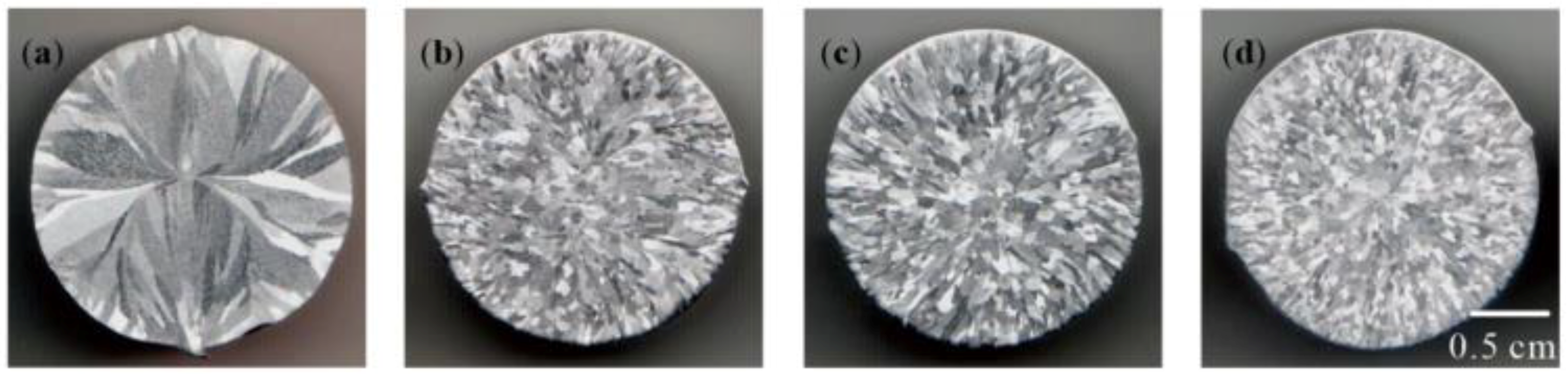
Figure 9.
The Ti–TiAlx mechanism in Ti-sponge route to prepare Al–Ti–B Master Alloy.
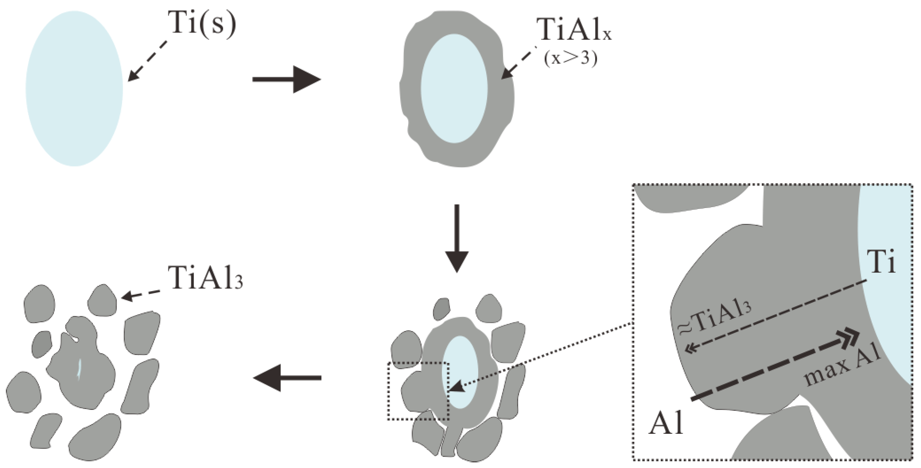
Figure 10.
The “rich Ti, B area” in different Al–Ti–B Master Alloy prepared routes at 800 °C for 15 S: (a) halide salt route; (b) 60% Ti-sponge route; (c) Ti-sponge route.
Figure 10.
The “rich Ti, B area” in different Al–Ti–B Master Alloy prepared routes at 800 °C for 15 S: (a) halide salt route; (b) 60% Ti-sponge route; (c) Ti-sponge route.
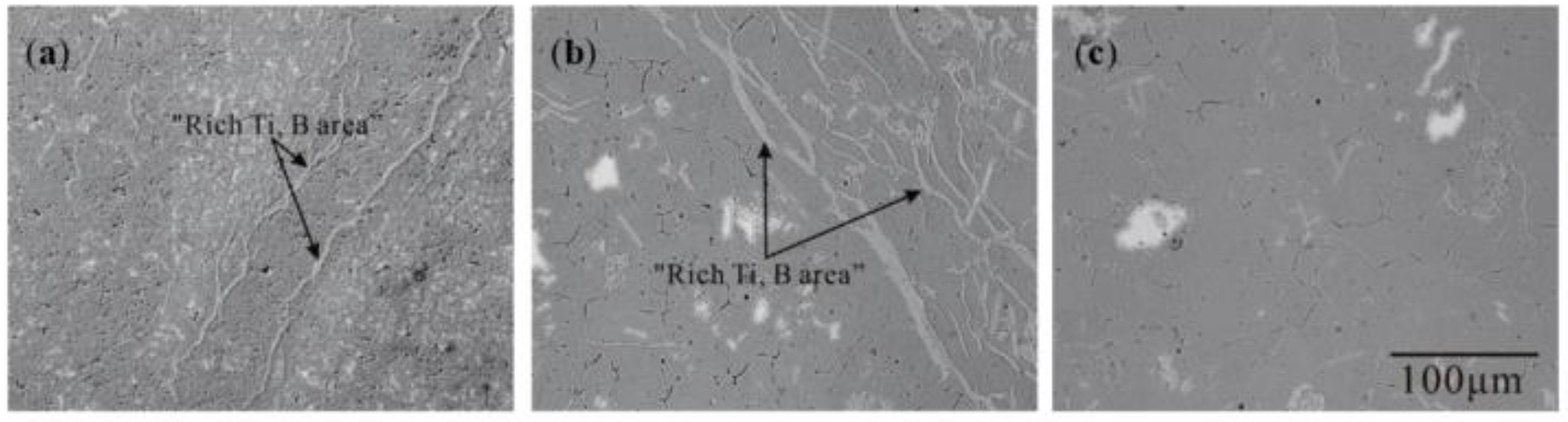
Figure 11.
Morphology of TiB2 for the halide salt route at 800 °C for different reaction times.
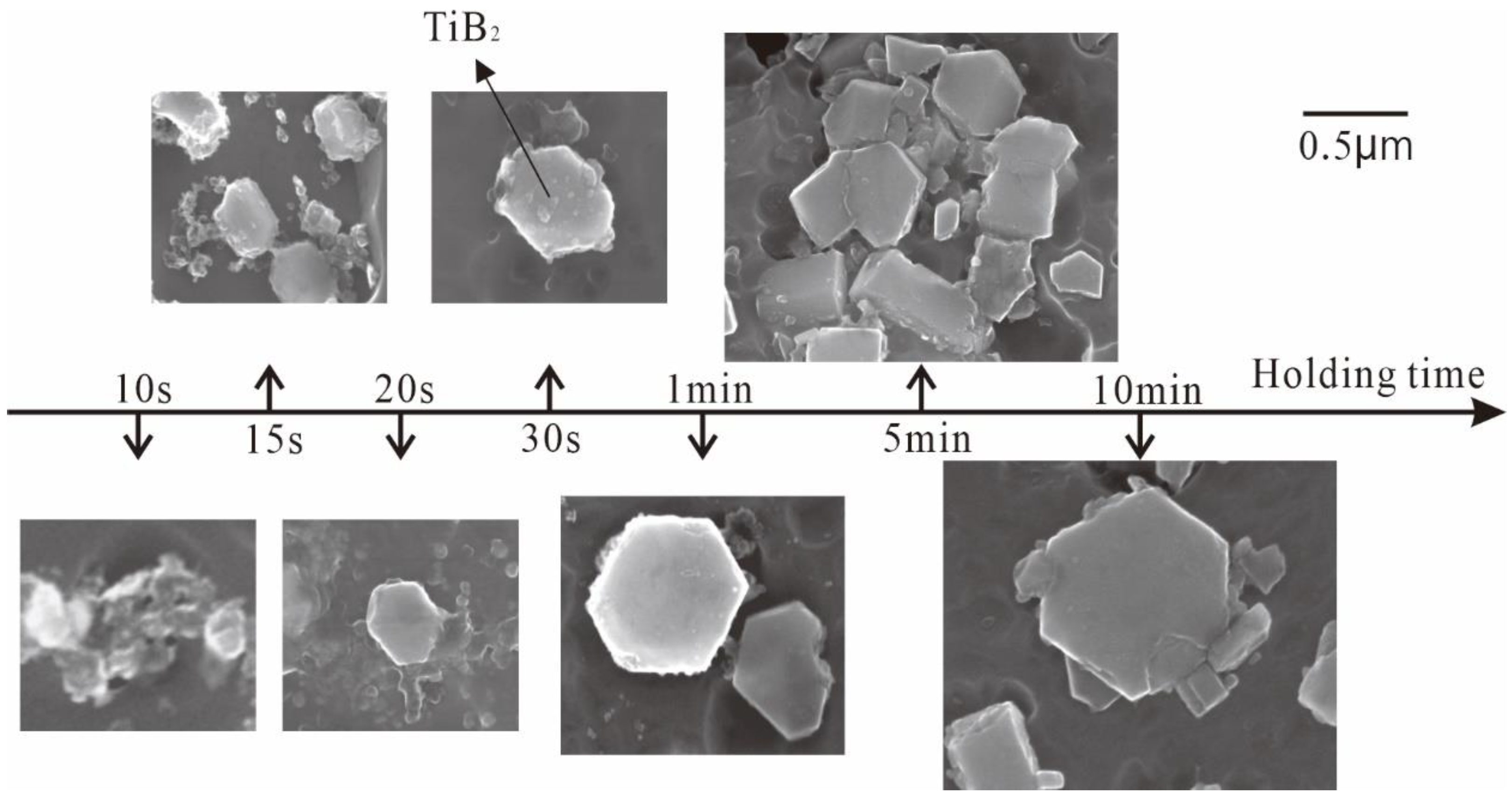
Figure 12.
Schematic diagram and microstructure of possible defects in the earlier and later growth stage of TiB2 for the Al–Ti–B Master Alloy prepared by the halide salt route: (a) earlier TiB2 crystal growth model; (b) earlier actual growth of TiB2; (c) later TiB2 crystal growth model; (d,e) later actual growth of TiB2.
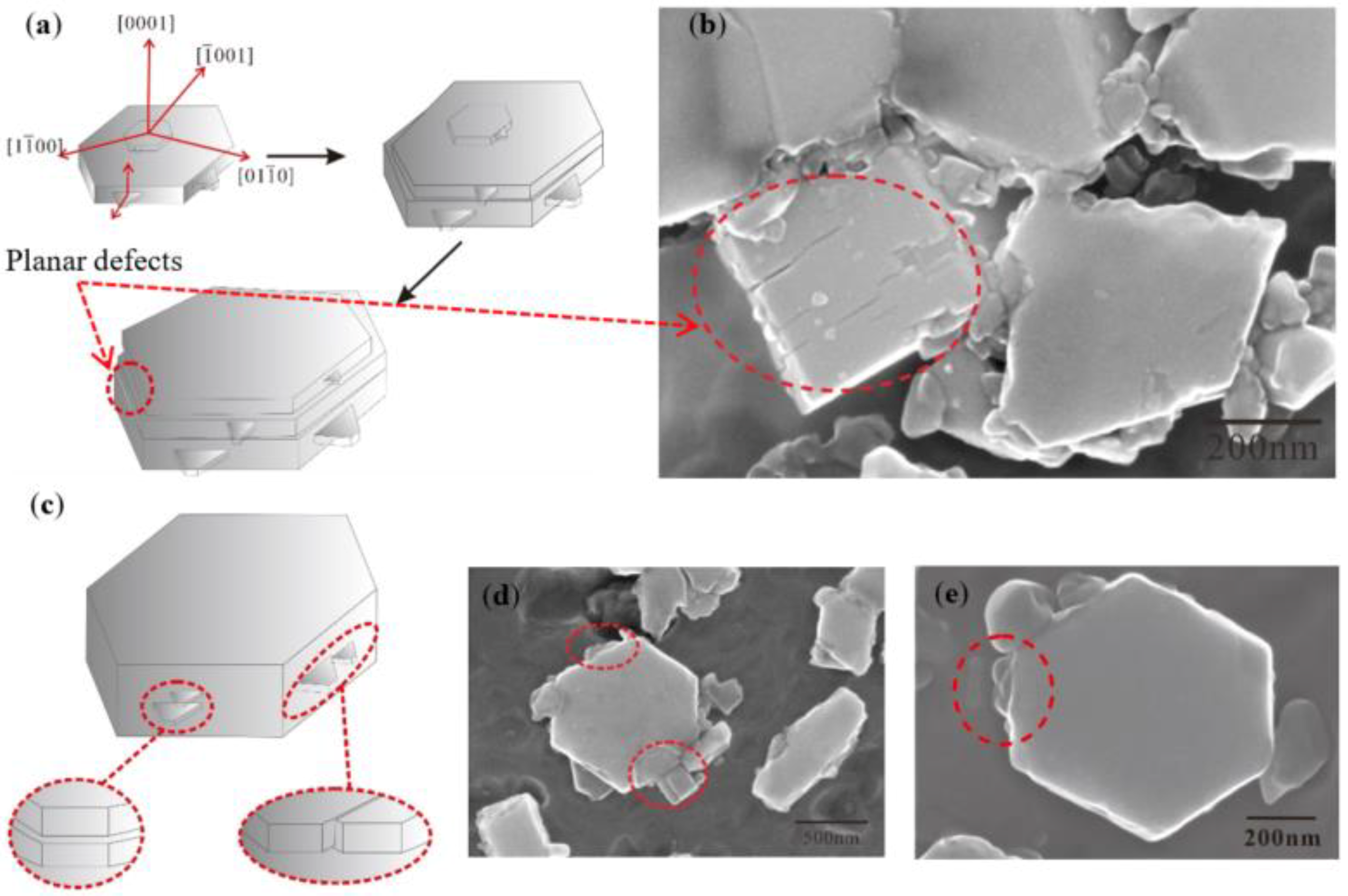
Figure 13.
SEM of the “rich Ti, B area” and TiB2 in the Al–Ti–B Master Alloy prepared by the halide salt route at 800 °C for 60 S.
Figure 13.
SEM of the “rich Ti, B area” and TiB2 in the Al–Ti–B Master Alloy prepared by the halide salt route at 800 °C for 60 S.


Table 1.
Experiment parameters for Al–5Ti–B Master Alloy prepared by the halide salt route.
| Temperature | Reaction Time | |||||||
|---|---|---|---|---|---|---|---|---|
| 800 °C | 10 S | 15 S | 20 S | 30 S | 60 S | 300 S | 600 S | 1800 S |
Table 2.
Experimental parameters for the partial Ti-sponge route and the Ti-sponge route.
| Content of Ti | Reaction Time | ||
|---|---|---|---|
| 30% Ti-sponge route | 15 S | 300 S | 1800 S |
| 60% Ti-sponge route | |||
| Ti-sponge route | |||
Publisher’s Note: MDPI stays neutral with regard to jurisdictional claims in published maps and institutional affiliations. |
© 2022 by the authors. Licensee MDPI, Basel, Switzerland. This article is an open access article distributed under the terms and conditions of the Creative Commons Attribution (CC BY) license (https://creativecommons.org/licenses/by/4.0/).
Share and Cite
MDPI and ACS Style
Zhao, Y.; Lu, Z.; Mi, L.; Hu, Z.; Yang, W. Morphological Evolution of TiB2 and TiAl3 in Al–Ti–B Master Alloy Using Different Ti Adding Routes. Materials 2022, 15, 1984. https://doi.org/10.3390/ma15061984
AMA Style
Zhao Y, Lu Z, Mi L, Hu Z, Yang W. Morphological Evolution of TiB2 and TiAl3 in Al–Ti–B Master Alloy Using Different Ti Adding Routes. Materials. 2022; 15(6):1984. https://doi.org/10.3390/ma15061984
Chicago/Turabian StyleZhao, Yanjun, Zepeng Lu, Li Mi, Zhiliu Hu, and Wenchao Yang. 2022. "Morphological Evolution of TiB2 and TiAl3 in Al–Ti–B Master Alloy Using Different Ti Adding Routes" Materials 15, no. 6: 1984. https://doi.org/10.3390/ma15061984
Note that from the first issue of 2016, this journal uses article numbers instead of page numbers. See further details here.