

Chemically Synthesized Iron-Oxide-Based Pure Negative Electrode for Solid-State Asymmetric Supercapacitor Devices
1
Department of Automotive Engineering, Yeungnam University, 280 Daehak-ro, Gyeongsan 38541, Korea
2
Division of Biotechnology, Daegu Gyeongbuk Institute of Science and Technology (DGIST), Daegu 42988, Korea
*
Author to whom correspondence should be addressed.
†
These authors contributed equally to this work.
Materials 2022, 15(17), 6133; https://doi.org/10.3390/ma15176133
Submission received: 27 May 2022
/
Revised: 23 July 2022
/
Accepted: 29 August 2022
/
Published: 3 September 2022
(This article belongs to the Special Issue Surface and Electrochemical Characterization of Nanomaterials)
Abstract
:Among energy storage devices, supercapacitors have received considerable attention in recent years owing to their high-power density and extended cycle life. Researchers are currently making efforts to improve energy density using different asymmetric cell configurations, which may provide a wider potential window. Many studies have been conducted on positive electrodes for asymmetric supercapacitor devices; however, studies on negative electrodes have been limited. In this study, iron oxides with different morphologies were synthesized at various deposition temperatures using a simple chemical bath deposition method. A nanosphere-like morphology was obtained for α-Fe2O3. The obtained specific capacitance (Cs) of α-Fe2O3 was 2021 F/g at a current density of 4 A/g. The negative electrode showed an excellent capacitance retention of 96% over 5000 CV cycles. The fabricated asymmetric solid-state supercapacitor device based on α-Fe2O3-NF//Co3O4-NF exhibited a Cs of 155 F/g and an energy density of 21 Wh/kg at 4 A/g.
1. Introduction
Currently, energy storage and conversion are the major issues in sustainable development, and renewable energy sources are sufficient to fulfill the increasing demand for global energy [1]. In the case of conventional energy storage devices, few limitations exist in the development of energy storage devices with good performance and efficiency [2]. Compared to conventional energy storage devices, supercapacitors are emerging energy storage devices with good cyclic stability, a rapid charge–discharge rate with high-power density, enhanced temperature range, and long cycle life, which may meet the ever-growing demand for energy storage devices [3]. Depending on the charge storage mechanism, supercapacitors are mainly categorized into two types: (1) electric double-layer (EDLC) supercapacitors and (2) pseudocapacitors [4]. EDLCs predominantly exhibit capacitance developed from charge accumulation (non-Faradaic) that occurs at the electrode–electrolyte interface [5]. In pseudocapacitors, pseudocapacitance is mainly caused by the redox reactions that occur in electrolytes and the electrically active surface of the electrode material [6]. In particular, transition metal oxides and polymers have predominantly been studied as pseudocapacitor materials [7]. The transition metal oxides, such as NiO, Co3O4, and MnO2, and double metal oxides, such as MCo2O4 (M = Mn, Ni, Fe), are used as positive electrodes [7,8,9,10,11]. However, in the case of an asymmetric solid-state supercapacitor (ASC) device, the performance depends on both positive and negative electrodes. The capacitance of the cell was measured using the following formula [12]:
where C+ and C− are the specific capacitances (Cs) of the anode and cathode, respectively. According to a study, the Cs values observed in the case of the anode are higher than those of the cathode [13]. Therefore, identifying negative electrode materials with an enhanced electrochemical performance is challenging. Among the transition metal oxides, iron oxide has emerged as a potential negative electrode material. Fe2O3 is a naturally abundant metal oxide; it shows a more negative working potential with higher stability in alkaline electrolytes, in addition to a high theoretical capacity (3625 F/g) [9,14]. In the case of Fe2O3, the charges are mainly stored using Faradaic redox reactions that occur between the Fe3+ and Fe2+ ions and the electrolyte at the interface of the electrode and electrolyte [15,16,17,18]. Compared to other metallic oxides, α-Fe2O3 is a good pseudocapacitive material. This may be due to its special crystal structure, such as α-Fe2O3 (hematite), which has a steadier hexagonal-like crystal structure [19]. However, there are a few limitations in the usage of α-Fe2O3 as an electrode material, such as low electrical conductivity, and the particle size of α-Fe2O3 increases with the number of charge–discharge cycles [20].
Therefore, efforts are prevailing to design different nanostructured morphologies of iron oxide directly grown on conducting nickel foam (NF) substrates. The nanostructured porous morphology of α-Fe2O3 is suitable for improving the electrochemical performance because of the presence of a large number of active sites, which provide a large active surface area for charging–discharging reactions [18,19]. These active sites help in reducing the diffusion length and transfer resistance of electrons, which helps sustain a constant rate capability at high resistance [21]. Herein, α-Fe2O3 films were grown directly on NF substrates using a simple chemical bath deposition (CBD) method at different deposition temperatures. At 363 K, porous nonspherical particles of α-Fe2O3 were formed directly on the conducting NF substrate. For the fabrication of the ASC device, Co3O4-NF was used as the positive electrode, and the synthesized α-Fe2O3-NF electrode was used as the negative electrode. This ASC device showed a good energy density of 21.5 Wh k/g. The negative electrode show a good stability of 96% with improved Cs of 1037 F/g for KOH-based electrolytes.
2. Materials and Methods
2.1. Synthesis of Negative α-Fe2O3-NF Electrode
The α-Fe2O3 thin films were synthesized using a simple CBD method. Briefly, 0.1 M [Fe(NO3)2∙6H2O] (ferric nitrate) was dissolved in 25 mL of deionized water (DI) and kept under continuous stirring, and then 0.2 M [CO(NH2)2] (urea) was dissolved in the mixture and stirred for 25 min to form a uniform reaction mixture. A thoroughly cleaned NF substrate was then inserted into the solvent mixture. The beaker containing the reaction mixture was then kept in a constant-temperature water bath at different deposition temperatures, such as 353 (S1), 363 (S2), and 373 K (S3), for 3 h [22].
After deposition, the brown thin film was removed from the bath, washed repeatedly with DI water, and dried at room temperature for 5 h. A schematic of the synthesis of α-Fe2O3 is shown in Scheme 1. In addition, the brown Fe2O3 thin film confirmed the formation of α-Fe2O3 nanoparticles.
2.2. Synthesis of the Positive Co3O4-NF Electrode
In the facile synthesis of the positive electrode, Co3O4-NF was synthesized using a previously reported CBD method [23]. A reaction mixture of 0.1 M [Co(NO3)2] (cobalt nitrate) and 0.2 M [CO(NH2)2] (urea) was formed in 25 mL of DI water. This reaction mixture and the cleaned NF substrate were maintained at 363 K for 5 h. The as-deposited thin films were dried in air and annealed at 623 K.
3. Results and Discussion
3.1. Structural and Morphological Characterization of the Negative α-Fe2O3-NF Electrode
The XRD patterns of the S1, S2, and S3 thin films are shown in Figure 1a. The observed high-intensity peaks correspond to (012), (104), (110), (113), (024), (116), (214), and (300) planes and match well with the JCPDS card no. 79-0007. The α phase of the Fe2O3 thin film formation is confirmed by the peak position [24]. The different deposition temperatures affected the nucleation rate, surface structure, and growth direction of the α-Fe2O3 thin films. For the S2 sample, the observed high-intensity peaks correspond to the (013), (104), and (115) planes. Further, the intensities of the XRD peaks for the S1 sample decreased due to the incomplete growth of particles, while in the case of the S3 sample, the film peeled up from the NF substrate; therefore, it showed a low intensity [25]. The crystal structure of α-Fe2O3 was reproduced using the VISTA software, as shown in Figure 1b. The brown and red balls represent the Fe and O elements, respectively, and the CIF file was downloaded from the crystallography open database [26]. XPS analysis was performed to study the composition and bonding of α-Fe2O3. The survey scan spectra of α-Fe2O3 are shown in Figure 1c. The high-resolution survey scan spectra confirmed the presence of Fe 2p, O 1s, and C 1s. The Fe 2p spectrum shows two pronounced peaks positioned at 711.4 (Fe 2p3/2) and 724.4 eV (Fe 2p1/2), respectively (Figure 1d). The binding energy difference between the two peaks is 13.5 eV, which agrees well with the previously reported literature for the Fe 2p spectrum [27]. The two satellite peaks are present near the main peak at the binding energies of 719.2 and 732.4 eV, which shows that the oxidation phase is Fe3+. The O 1s core-level peak was resolved into two peaks at binding energies of 529.4 and 531.2 eV (Figure 1e) [28]. The peak at 529.4 eV was mainly due to lattice oxygen (FeO), and that at 531.2 eV was due to surface hydroxyl (–OH) [29,30].
Figure 2 shows the surface morphologies of the α-Fe2O3 thin films (S1, S2, and S3). At low temperatures, the rhombohedra with connected edge-like morphologies were obtained for the S1 sample (Figure 2a–c). In addition, owing to the low reaction temperature, the rate of reaction was reduced, which affected the process of thin-film formation, such as nucleation, aggregation, and growth [31,32]. A further increase in deposition temperature resulted in nanosphere-like morphology, as shown in Figure 2d–f. The particle size was found in the range of 30–40 nm from the SEM observation. This nanosphere-like morphology mainly enhances the electrochemical properties. At higher temperatures, agglomeration of the particles occurred (Figure 2g–i). The morphology of α-Fe2O3 was further confirmed using TEM. Figure 3a,b show the TEM images of S2, which are in good agreement with the SEM data.
3.2. Electrochemical Performance of the α-Fe2O3-NF Electrode
Figure 4a shows the CV curves of the S1, S2, and S3 samples at 100 mV/s. The area under the curve for the S2 sample was greater than that of the S1 and S3 samples. The electrochemical study for the negative α-Fe2O3-NF electrode(S2) was tested in a 2 M KOH electrolyte in the operating potential window range from 0.0 to −1.0 V Ag/AgCl. The CVs of the α-Fe2O3-NF electrodes were studied at various scan rates (Figure 4b). The CV curves for α-Fe2O3-NF at −1 and −1.2 V are shown in Figure A1. The shape of the CV curve was semi-rectangular, owing to the reversible redox reactions occurring between the Fe3+ and Fe2+ ions in the KOH electrolyte. This study substantiates the pseudocapacitive nature of the α-Fe2O3 electrode [32]. At lower scan rates, such as 5 mV/s, the available duration for the OH− ions in the electrolyte (KOH) to intercalate with the electrode material (α-Fe2O3-NF) is the maximum, which may be responsible for the enhancement of Cs. The charging mechanism in the α-Fe2O3-NF electrode is shown in the following reaction [33,34]:
The GCD curves for α-Fe2O3 at various current densities in the operating window, ranged from 0.0 to −1.0 V Ag/AgCl, are shown in Figure 4c. The GCD curve shows the nonlinear nature of the discharge curve owing to the redox reactions occurring at the interface. The Cs value of the α-Fe2O3 electrode at a current density of 4 A/g was 2125 F/g, which was calculated using Equation (A1) in the Appendix. The cyclic stability performance also decreased after 5000 GCD cycles, as shown in Figure A2. Figure 4d shows the variations in Cs with various current densities. The inset of Figure 4e shows the stability of the α-Fe2O3-NF electrode, tested using CV cycling at 100 mV/s (scan rate) for 5000 CV cycles. Figure 4e shows the plot of capacity retention vs. cycle number, and the observed electrochemical stability of the α-Fe2O3-NF electrode was 96%. The improved performance of the α-Fe2O3-NF electrode was predominantly due to its porous morphology, which decreases the diffusion length and increases the rate capability. In addition, the α-Fe2O3 nanospheres were strongly attached to the conductive NF substrate, which prevented the loss of the active material during the cyclic stability performance study. The electrochemical performance of the α-Fe2O3-NF electrode is given in Table A1 (Appendix A). Therefore, the nanosphere-like α-Fe2O3-NF electrode is suitable for use as a negative electrode in the fabrication of ASC devices. The calculated b-value is 0.7 at the cathodic potential, which is close to 0.5, rather than 1, proving that the charge storage mechanism originates from the dominant diffusion-controlled process, as shown in Figure A3a. In addition, Figure A3b shows the capacitive and diffusive current-controlled distribution for the α-Fe2O3 electrode [35].
3.3. Structural and Morphological Characterization of the Positive Co3O4-NF Electrode
A nanowire-like Co3O4-NF thin film was synthesized using a facile CBD method. The XRD pattern of the deposited Co3O4 is shown in Figure 5a. The peaks observed at 31.4°, 36.9°, 44.9°, 59.4°, and 65.3° are indexed to planes corresponding to (220), (311), (400), (422), and (511), respectively, according to JCPDS card no:42-1467. Figure 5b shows the FE-SEM image for Co3O4-NF. The observed nanowire-like morphology is uniformly distributed on the surface of the NF substrate. The nanowire-like morphology of Co3O4-NF provides less resistance value and porous structure, which improves the reaction rate [36]. Figure 5c,d show the TEM images of the Co3O4-NF electrode, which substantiates its nanowire-like nature.
3.4. Electrochemical Performance of the Positive Co3O4-NF Electrode
The electrochemical study of the Co3O4-NF electrode was conducted in a 2 M KOH electrolyte. The CV curves of the Co3O4-NF electrode are shown in Figure 6a. The CV curves for the Co3O4-NF electrode show the presence of a pair of redox peaks, which originate from the Faradaic reactions that occur at the electrode surface, and are presented below [37,38,39]:
The GCD curve of the Co3O4-NF electrode is shown in Figure 6b. The GCD curve exhibits a nearly symmetric nature with the same charging and discharging times and a low value of internal resistance [39]. Figure 6c displays Cs observed at various current densities. The Cs value observed at 4 A/g is approximately 1032 F/g. The cyclic stability of the Co3O4-NF electrode studied for the 5000th CV cycle is presented in Figure 6d, and the inset shows the stability study at 5000 CV cycles for the Co3O4-NF thin film. The observed b-value is 0.45 at the cathodic potential, which is close to 0.5, rather than 1, as shown in Figure A3c. This indicates that the charge storage contributions originate from the dominant diffusion-controlled processes. Figure A3d shows the capacitive and diffusion-controlled contributions of the Co3O4-NF electrode. As the scan rate increased, the capacitive contribution to the total charge increased. A major diffusion-controlled process for the Co3O4-NF electrode was observed at all of the scan rates, which is consistent with the battery-type nature of the electrode during the charge/discharge process.
3.5. Supercapacitive Performance of the Solid-State Co3O4-NF//α-Fe2O3-NFASC Device
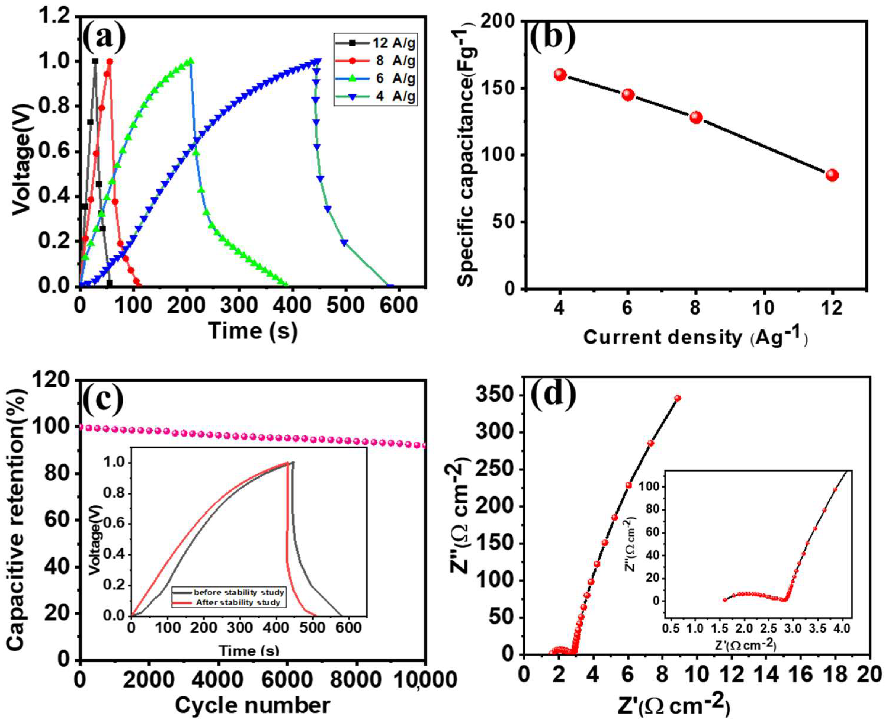
In this study, an ASC device was fabricated using Co3O4-NF and α-Fe2O3-NF as the positive and negative electrodes, respectively, with PVA-KOH as the solid-state electrolyte (Figure 7a). The charges across the Co3O4-NF and α-Fe2O3-NF electrodes were balanced using Equation (1). The mass loaded on both positive (Co3O4-NF) and negative electrodes (α-Fe2O3-NF) are 1.85 and 2.15 mg/cm2, respectively. Figure 7b shows the CV profile of the Co3O4-NF//α-Fe2O3-NF ASC device at various scan rates in the potential window of 0–1.0 V. The specific capacitance calculated for the Co3O4-NF//α-Fe2O3-NF device was approximately 164 F/g, as shown in Figure 7c. In the case of electrochemical double-layer capacitance, the ideal shape of the CV is rectangular, and the mirror image and current density are independent of the operating potential of the energy storage device during the discharge process [40]. The CV curves for the ASC device at different angles, such as 0°, 45°, 90°, 120°, and 180°, are shown in Figure A4a (Appendix A). The shape of the CV curve is not an ideal rectangular redox peak, and the shapes of the CV curves do not change [41,42,43]. The GCD curves for the Co3O4-NF//α-Fe2O3-NF ASC device at current densities of 4–12 A/g are shown in Figure 8a. The GCD curves show nearly symmetric charge–discharge curves. In addition, the voltage plateaus observed in all of the GCD curves confirm the contribution of the capacitance originating from the pseudocapacitive nature of the electrode [42]. The Cs values calculated from the GCD curves were plotted as a function of the current density (Figure 8b). The device delivered a high Cs of 160 F/g at 4 A/g. Figure A4b shows the Ragone plot of the energy density vs. power density for the fabricated Co3O4-NF//α-Fe2O3-NF ASC device. The maximum energy density of the device was observed up to 21.5 Wh/kg at a power density of 158.2 W/kg and a current density of 4 g−1. Table A2 in Appendix A shows the electrochemical performance of the ASC device, based on Co3O4-NF//α-Fe2O3-NF. The stability of the Co3O4-NF//α-Fe2O3-NF ASC device was tested using the GCD technique for 10,000 cycles. The capacitance retention of the Co3O4-NF//α-Fe2O3-NF ASC device is approximately 92%, as shown in Figure 8c. In addition, no significant difference was observed in the GCD curves before and after the stability study (Figure 8c). Furthermore, the electrochemical properties of the Co3O4-NF//α-Fe2O3-NF ASC device were studied using EIS. Figure 8d shows the Nyquist plot for the Co3O4-NF//α-Fe2O3-NF ASC device in the frequency range of 5 kHz to 50 MHz (5 mV), and the inset shows the high-frequency region. The obtained values of series resistance (Rs) and charge transfer resistance (Rct) for the Co3O4-NF//α-Fe2O3-NF ASC device are 0.15 and 2.5 Ω/cm2, respectively. Thus, the ACS device based on Co3O4-NF//α-Fe2O3-NF exhibited good electrochemical properties.
4. Conclusions
Nanosphere-like α-Fe2O3 was uniformly deposited on an NF substrate using a simple CBD technique. The porous nature of α-Fe2O3 contributed to its good specific capacitance with enhanced cyclic stability. The Co3O4-NF//α-Fe2O3-NF device, fabricated using Co3O4-NF and α-Fe2O3-NF as the positive and negative electrodes, respectively, shows the maximum specific capacitance (Cs) of 164 F/g at a current density of 4 A/g. The maximum energy density of the device was observed up to 21.5 Wh/kg at a power density of 158.2 W/kg, with excellent rate capability. In addition, the Co3O4-NF//α-Fe2O3-NF ASC device showed a capacitance retention of 92% after 10,000 cycles of GCD. The outstanding performance of α-Fe2O3-NF makes it one of the favorable negative electrode materials for high-performance energy storage devices.
Author Contributions
Conceptualization, S.-W.K.; methodology, A.A.Y.; formal analysis, A.A.Y.; investigation, A.A.Y. and S.K.; resources, S.-W.K.; writing—original draft preparation, A.A.Y.; writing—review and editing, A.A.Y., Y.M.H. and S.-W.K.; supervision, S.-W.K.; validation, S.K.; visualization, S.K.; project administration, S.-W.K.; funding acquisition, S.-W.K. All authors have read and agreed to the published version of the manuscript.
Funding
This work was supported by the National Research Foundation of Korea (NRF) grant funded by the Korean government (MSIT) (No. 2019R1A5A8080290). In addition, this work was partly supported by the Korea Institute of Energy Technology Evaluation and Planning (KETEP) grant funded by the Korean government (MOTIE) (20214000000010, Gyeongbuk Regional Wind Energy Cluster Human Resources Development Project).
Institutional Review Board Statement
Not applicable.
Informed Consent Statement
Not applicable.
Data Availability Statement
The data presented in this study are available on request from the corresponding author. The data are not publicly available.
Conflicts of Interest
The authors declare no conflict of interest.
Appendix A
Appendix A.1. Materials Characterization
The formation of α-Fe2O3-NF and Co3O4-NF was confirmed by X-ray diffraction (XRD, Bruker AXS D8 advance model) analysis. The surface morphology of α-Fe2O3-NF and Co3O4-NF was examined by field emission scanning electron microscopy (FE-SEM) and transmission emission electron microscopy (TEM). X-ray photoelectron spectroscopy (XPS) analysis of the powdered sample (~1–5 mg) of α-Fe2O3-NF was performed to determine the chemical composition and oxidation states (X-ray source: monochromatic AI Kα, ultimate energy resolution and It = 0.50 eV FWHM, Ag3d intensity curve).
Appendix A.2. Electrochemical Characterization
The electrochemical performances of the α-Fe2O3-NF and Co3O4-NF electrodes were tested using a three-electrode system on a ZIVE SP2 battery cycler. In the case of the three-electrode system, α-Fe2O3-NF and Co3O4-NF electrodes (1 cm2) were used as the working electrodes, platinum wire as the counter electrode, and Ag/AgCl as the reference electrode. The electrochemical properties were tested in a 2 M KOH electrolyte. The specific capacity (Qs) and specific capacitance (Cs) were calculated from the discharge curve using the following formulas [43]:
where i, Δt, m, and ΔV are the discharge current density (A), discharge time (s), mass of the active material (g), and potential window (V), respectively.
Appendix A.3. Asymmetric Supercapacitor Device Based on α-Fe2O3-NF//Co3O4-NF
To fabricate a flexible asymmetric supercapacitor device, α-Fe2O3-NF and Co3O4-NF electrodes were used as the negative and positive electrodes, respectively. PVA-KOH was used as the gel polymer electrolyte and separator. The PVA-KOH electrolyte was prepared using a previously reported method [44]. The α-Fe2O3-NF and Co3O4-NF electrodes were painted with the PVA-KOH electrolyte and allowed to solidify at room temperature. This process was repeated 2 to 3 times to ensure that a sufficient amount of electrolyte was coated on the electrode surface. After the solidification process, the two electrodes were sandwiched, and the device was packed and tested. The Cs, energy density, and power density values were calculated using a previously reported formula [42]. The charges between the cathode and anode can be balanced for excellent electrochemical results for the ASC device using the theory of mass balance as per the following equation:
where m(+ or −), ΔV(+ or −), and C(+ or −) are the mass of the active material (g), potential window (ΔV), and Cs (F/g) of the positive and negative electrodes, respectively. The mass ratio calculated between the positive and the negative electrodes is 1:1.56. The specific capacitance (Csc, F/g), specific energy (E, Wh/kg), and specific power (P, W/kg) of the ASC cell were calculated using the following equations:
Figure A1.
CV curves for α-Fe2O3-NF in −1 V and −1.2 V at 100 mV/s.
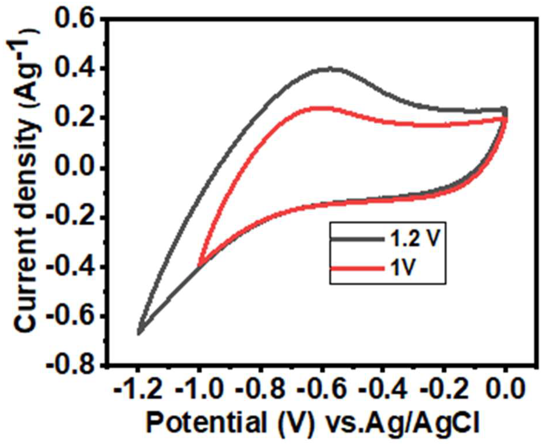
Figure A2.
Stability test results for 5000 charge–discharge cycles at a current density of 5 A/g.
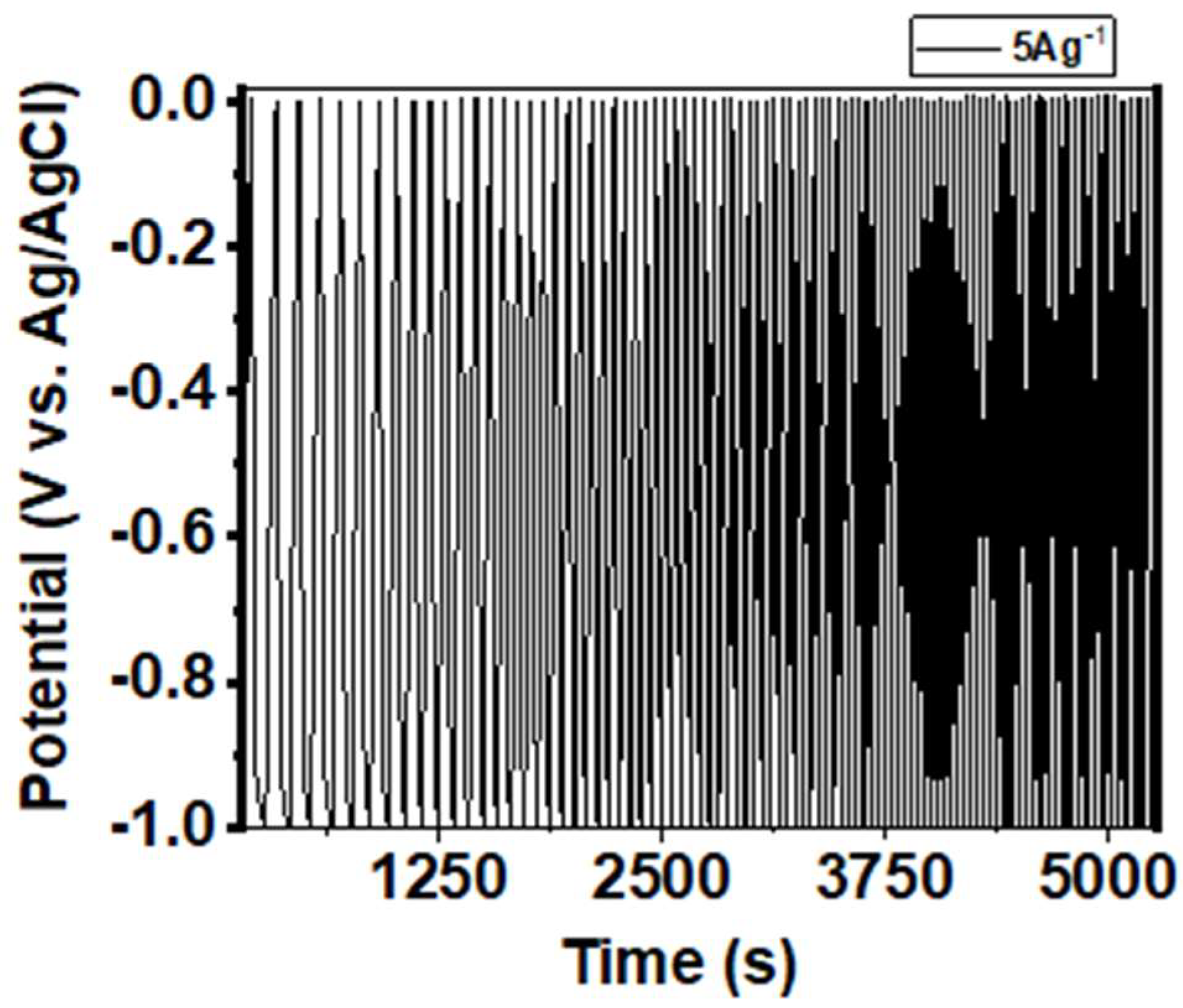
Figure A3.
(a,c) Plot of current vs. scan rate in log-scale to calculate the b-value, (b,d) the plot of capacitive and diffusion-controlled current contributions with scan rates corresponding to Fe2O3 and Co3O4, respectively.
Figure A3.
(a,c) Plot of current vs. scan rate in log-scale to calculate the b-value, (b,d) the plot of capacitive and diffusion-controlled current contributions with scan rates corresponding to Fe2O3 and Co3O4, respectively.
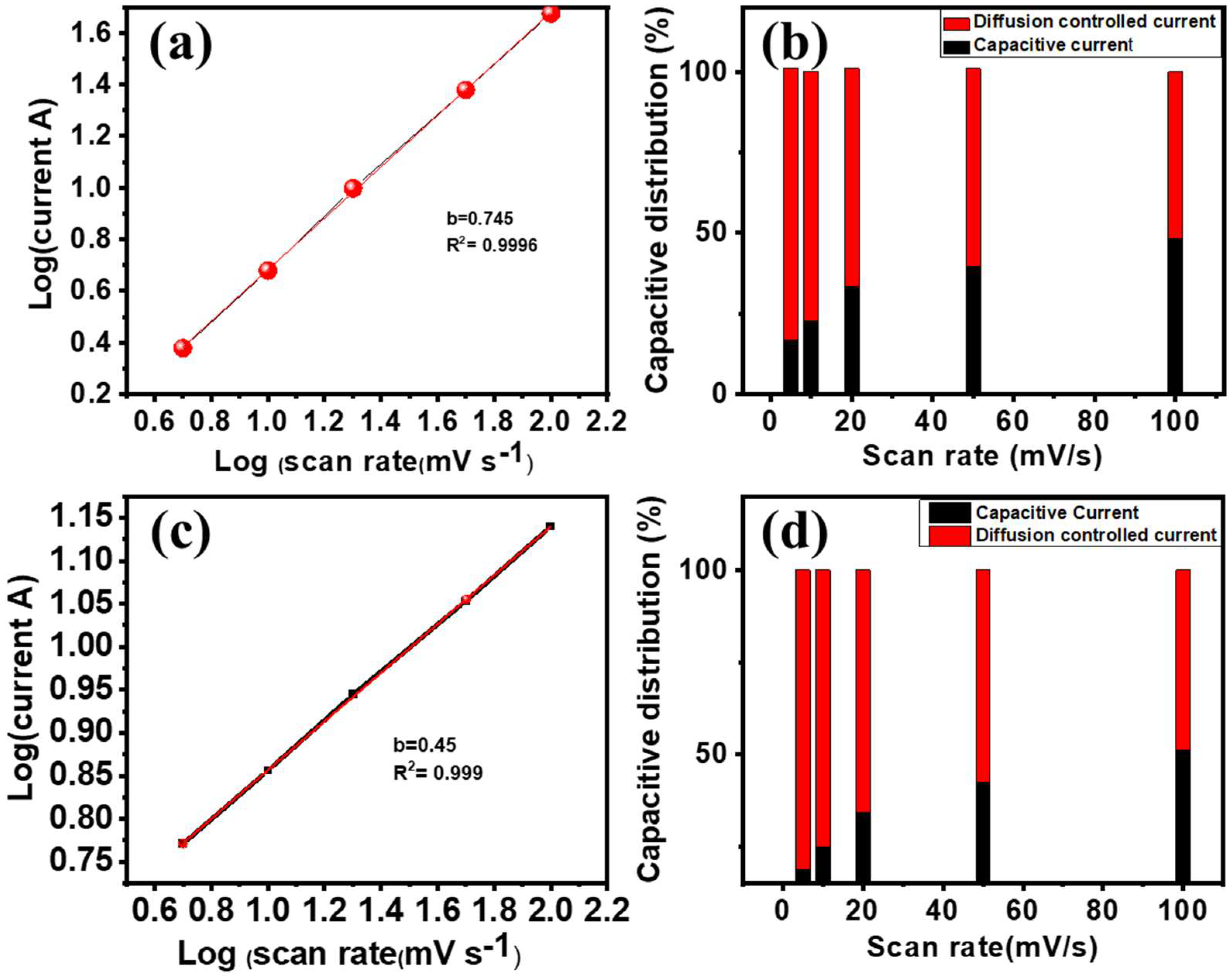
Figure A4.
(a) CV curves at different angles, (b) the Ragone plot for the Co3O4-NF//Fe2O3-NF ASC device.
Figure A4.
(a) CV curves at different angles, (b) the Ragone plot for the Co3O4-NF//Fe2O3-NF ASC device.


Table A1.
The electrochemical performance of the ferric-oxide-based negative electrode.
| Material | Electrolyte | Capacitance | Stability | Ref. |
|---|---|---|---|---|
| Fe2O3/CF | 5 M LiCl | 180.4 mF/cm2 | - | [44] |
| Fe2O3-C | 3 M KOH | 247.5 mAh/g (2 mV/s) | 64% (5000) | [42] |
| Fe2O3 NF | 5 M LiCl | 145.9 mF/cm2 10 mA/cm2 | 87.2% (5000) | [45] |
| Fe2O3@C | 6 M KOH | 304.9 at 1 A/g | 90.7% (2000) | [46] |
| CF-Fe2O3 | 2 M KOH | 1.56 F/cm2 at 10 mA/cm2 | 102% (5000) | [47] |
| Fe2O3/CF | 0.5 M LiClO4 | 261 F/g at 1 A/g | 82.7% (10,000) | [48] |
| Fe2O3/CF | 2 M KOH | 908 F/g at 10 A/g | 90% (5000) | [36] |
| Fe2O3-NF | 2 M KOH | 2125 F/g at 4 A/g | 95.2% (5000) | Present work |
Table A2.
The electrochemical performance of the ferric-oxide-based ASC devices.
| ASC Devices | Electrolyte | Specific Capacitance | Energy Density | Power Density | Ref. |
|---|---|---|---|---|---|
| CuO//Fe2O3 | CMC-Na2SO4 | 79 F/g | 23 Wh/kg | 19 kW/kg | [49] |
| MnO2@CuO//Fe2O3@C | PVA-LiCl | 2.46 F/cm3 (0.13 A/cm2) | 0.85 mWh/cm3 | 0.1 W/cm3 | [50] |
| CF-Co3O4//CF-Fe2O3 | PVA-KOH | 17.5 F/cm3 (6 mA/cm2) | 6.75 mWh/cm3 | 104 mW/cm3 | [51] |
| MnO2///Fe2O3 | PVA-LiClO4 | 74 F/g (5 mV/s) | 33.1 Wh/kg | 1.32 kW/kg | [44] |
| MnO2//Fe2O3 | PVA-LiCl | 1.21 F/cm3 (0.5 mA/cm2) | 0.41 mWh/cm3 | - | [51] |
| MnO2/CF//Fe2O3/CF | PVA-LiCl | 1.5 F/cm3 (0.5 mA/cm2) | 0.55 mWh/cm3 | - | [44] |
| NiO//Fe2O3 | PVA KOH | 57.2 F/g | 12.4 Wh/kg | 951 W/kg | [32] |
| Co3O4-NF//Fe2O3-NF | PVA KOH | 155 F/g | 21.5 Wh/kg | 158 kW/kg | Present work |
References
- Miller, J.R.; Simon, P. Electrochemical capacitors for energy management. Science 2008, 321, 651–652. [Google Scholar] [CrossRef] [PubMed]
- Simon, P.; Gogotsi, Y. Materials for electrochemical capacitors. Nat. Mat. 2008, 7, 845–854. [Google Scholar] [CrossRef] [PubMed]
- Zhou, Q.; Xing, J.; Gao, Y.; Lv, X.; He, Y.; Guo, Z.; Li, Y. Ordered assembly of NiCo2O4 multiple hierarchical structures for high-performance pseudocapacitors. ACS Appl. Mater. Interfaces 2014, 6, 11394–11402. [Google Scholar] [CrossRef] [PubMed]
- Du, J.; Zhou, G.; Zhang, H.; Cheng, C.; Ma, J.; Wei, W.; Chen, L.; Wang, T. Ultrathin porous NiCo2O4 nanosheet arrays on flexible carbon fabric for high-performance supercapacitors. ACS Appl. Mater. Interfaces 2013, 5, 7405–7409. [Google Scholar] [CrossRef]
- Zhou, W.; Kong, D.; Jia, X.; Ding, C.; Cheng, C.; Wen, G. NiCo2O4 nanosheet supported hierarchical core–shell arrays for high-performance supercapacitors. J. Mater. Chem. A 2014, 2, 6310–6315. [Google Scholar] [CrossRef]
- Cai, D.; Xiao, S.; Wang, D.; Liu, B.; Wang, L.; Liu, Y.; Li, H.; Wang, Y.; Li, Q.; Wang, T. Morphology controlled synthesis of NiCo2O4 nanosheet array nanostructures on nickel foam and their application for pseudocapacitors. Electrochim. Acta 2014, 142, 118–124. [Google Scholar] [CrossRef]
- Zhang, G.; Lou, X. Controlled growth of NiCo2O4 nanorods and ultrathin nanosheets on carbon nanofibers for high-performance supercapacitors. Sci. Rep. 2013, 3, 1470. [Google Scholar] [CrossRef]
- Zhou, J.; Huang, Y.; Cao, X.; Ouyang, B.; Sun, W.; Tan, C.; Zhang, Y.; Ma, Q.; Liang, S.; Yan, Q.; et al. Two-dimensional NiCo2O4 nanosheet-coated three-dimensional graphene networks for high-rate, long-cycle-life supercapacitors. Nanoscale 2015, 7, 7035–7039. [Google Scholar] [CrossRef]
- Li, Y.; Li, Q.; Cao, L.; Cui, X.; Yang, Y.; Xiao, P.; Zhang, Y. The impact of morphologies and electrolyte solutions on the supercapacitive behavior for Fe2O3 and the charge storage mechanism. Electrochim. Acta 2015, 178, 171–178. [Google Scholar] [CrossRef]
- Zhang, G.; Lou, X.W. General solution growth of mesoporous NiCo2O4 nanosheets on various conductive substrates as high-performance electrodes for supercapacitors. Adv. Mater. 2013, 25, 976–979. [Google Scholar] [CrossRef]
- Nithya, V.D.; Arul, N.S. Progress and development of Fe3O4 electrodes for supercapacitors. J. Mater. Chem. A 2016, 4, 10767–10778. [Google Scholar] [CrossRef]
- Khatavkar, S.N.; Sartale, S.D. α-Fe2O3 thin films by liquid phase deposition: Low-cost option for supercapacitor. J. Solid State Electrochem. 2016, 21, 2555–2566. [Google Scholar] [CrossRef]
- He, Y.M.; Chen, W.J.; Li, X.D.; Zhang, Z.X.; Fu, J.C.; Zhao, C.H.; Xie, E.Q. Freestanding three-dimensional graphene/MnO2 composite networks as ultralight and flexible supercapacitor electrodes. ACS Nano 2013, 7, 174–182. [Google Scholar] [CrossRef] [PubMed]
- Meng, W.; Wei, C.; Lei, Z.; Yang, H.; Zhu, M.; Yan, H.; Fu, Y.; Geng, F.; Jie, Y.; Chen, X. Porous Fe3O4/carbon composite electrode material prepared from metal-organic framework template and effect of temperature on its capacitance. Nano Energy 2014, 8, 133–140. [Google Scholar] [CrossRef]
- Li, Y.; Shen, W. Morphology-dependent nanocatalysts: Rod-shaped oxides. Chem Soc. Rev. 2014, 43, 1543–1574. [Google Scholar] [CrossRef]
- Mishra, M.; Chun, D.M. Alpha-Fe2O3 as a photocatalytic material: A review. Applied Catalysis A: General. Appl. Catal. A 2015, 498, 126–141. [Google Scholar] [CrossRef]
- Upadhyay, K.K.; Nguyen, T.; Silva, T.M.; Carmezim, M.J.; Montemor, M.F. Electrodeposited MoOx films as negative electrode materials for redox supercapacitors. Electrochim. Acta 2017, 225, 19–28. [Google Scholar] [CrossRef]
- Lu, X.; Yu, M.; Zhai, T.; Wang, G.; Xie, S.; Liu, T.; Liang, C.; Tong, Y.; Li, Y. High energy density asymmetric quasi-solid-state supercapacitor based on porous vanadium nitride nanowire anode. Nano Lett. 2013, 13, 2628–2633. [Google Scholar] [CrossRef]
- Li, J.; Wu, Q.; Zan, G. A high-performance supercapacitor with well-dispersed Bi2O3 nanospheres and active-carbon electrodes. Eur. Inorg. Chem. 2015, 201, 5751–5756. [Google Scholar] [CrossRef]
- Bak, C.; Kim, K.; Jung, K.; Kim, J.B.; Jang, J.H. Efficient photoelectrochemical water splitting of nanostructured hematite on a three-dimensional nanoporous metal electrode. J. Mater. Chem. A 2014, 2, 17249–17252. [Google Scholar] [CrossRef]
- Nithya, V.D.; Arul, N.S. Review on α-Fe2O3 based negative electrode for high performance supercapacitors. J. Power Sources 2016, 327, 297–318. [Google Scholar] [CrossRef]
- Hunge, Y.M. Photoelectrocatalytic degradation of 4-chlorophenol using nanostructured α-Fe2O3 thin films under sunlight illumination. J. Mar. Sci. 2017, 28, 11260–11267. [Google Scholar] [CrossRef]
- Yadav, A.A.; Hunge, Y.M.; Kulkarni, S.B. Chemical synthesis of Co3O4 nanowires for symmetric supercapacitor device. J. Mar. Sci. 2018, 29, 16401–16409. [Google Scholar] [CrossRef]
- Hjiri, M. Highly sensitive NO2 gas sensor based on hematite nanoparticles synthesized by sol–gel technique. J. Mar. Sci. Eng. 2020, 31, 5025–5031. [Google Scholar] [CrossRef]
- Xiao, T.; Che, P.; Xiao, R.; Xiang, P.; Jiang, L.; Tao, F.; Tan, X.; Chen, X. 3D interconnected Fe-Co-S nanosheets network directly grown on graphene coated nickel foam with enhanced electrochemical performance for asymmetric supercapacitors. Appl. Surf. Sci. 2021, 543, 148747. [Google Scholar] [CrossRef]
- Zachariasen, W.H. Skrifterutgittav det Norske Videnskaps-Akademi I Oslo 1: Matematisk—NaturvidenskpelingKlasse; New York Botanical Garden: Bronx, NY, USA, 1998; pp. 1–165. [Google Scholar]
- Wang, J.-C.; Ren, J.; Yao, H.-C.; Zhang, L.; Wang, J.-S.; Zang, S.-Q.; Han, L.-F.; Li, Z.-J. Synergistic photocatalysis of Cr (VI) reduction and 4-chlorophenol degradation over hydroxylated α-Fe2O3 under visible light irradiation. J. Hazard. Mater. 2016, 311, 11–19. [Google Scholar] [CrossRef]
- McIntyre, N.S.; Zetaruk, D.G. X-ray photoelectron spectroscopic studies of iron oxides. Anal. Chem. 1977, 49, 1521–1529. [Google Scholar] [CrossRef]
- Grosvenor, A.P.; Kobe, B.A.; Biesinger, M.C.; McIntyre, N.S. Investigation of multiplet splitting of Fe 2p XPS spectra and bonding in iron compounds. Surf. Interface Anal. 2004, 36, 1564–1574. [Google Scholar] [CrossRef]
- Lee, K.K.; Deng, S.; Fan, H.M.; Mhaisalkar, S.; Tan, H.R.; Tok, E.S.; Loh, K.P.; Chin, W.S.; Sow, C.H. α-Fe2O3 nanotubes-reduced graphene oxide composites as synergistic electrochemical capacitor materials. Nanoscale 2012, 4, 2958–2961. [Google Scholar] [CrossRef]
- Zhang, H.; Gao, Q.; Yang, K.; Tan, Y.; Tain, W.; Zhu, L.; Li, Z.; Yang, C. Solvothermally induced α-Fe2O3/graphene nanocomposites with ultrahigh capacitance and excellent rate capability for supercapacitors. J. Mater. Chem. A 2015, 3, 22005–22011. [Google Scholar] [CrossRef]
- Zhang, S.; Yin, B.; Wang, Z.; Peter, F. Super long-life all solid-state asymmetric supercapacitor based on NiO nanosheets and α-Fe2O3 nanorods. Chem. Eng. J. 2016, 306, 193–203. [Google Scholar] [CrossRef]
- Chen, Y.; Kang, C.; Ma, L.; Fu, L.; Li, G.; Hu, Q.; Liu, Q. MOF-derived Fe2O3 decorated with MnO2 nanosheet arrays as anode for high energy density hybrid supercapacitor. Chem. Eng. J. 2021, 417, 129243. [Google Scholar] [CrossRef]
- Tang, D.; Wang, W.; Wang, G. The perfect matching between the low-cost Fe2O3 nanowire anode and the NiO nanoflake cathode significantly enhance the energy density of asymmetric supercapacitors. J. Mater. Chem. A 2015, 3, 6662–6670. [Google Scholar] [CrossRef]
- Yadav, A.A.; Hunge, Y.M.; Liu, S.; Kulkarni, S.B. Ultrasound assisted growth of NiCo2O4@carbon cloth for high energy storage device application. Ultrason. Sonochem. 2019, 56, 290–292. [Google Scholar] [CrossRef]
- Yuan, C.; Yang, L.; Hou, L.; Shen, L.; Zhang, X.; Lou, X.W. Growth of ultrathin mesoporous Co3O4 nanosheet arrays on Ni foam for high-performance electrochemical capacitors. Energy Environ. Sci. 2012, 5, 7883–7887. [Google Scholar] [CrossRef]
- Zheng, Y.; Li, Z.; Xu, J.; Wang, T.; Liu, X.; Duan, X.; Ma, Y.; Zhou, Y.; Pei, C. Multi-channeled hierarchical porous carbon incorporated Co3O4 nanopillar arrays as 3D binder-free electrode for high performance supercapacitors. Nano Energy 2016, 20, 94–107. [Google Scholar] [CrossRef]
- Demarconnay, L.; Raymundo-Pinero, E.; Beguin, F. Adjustment of electrodes potential window in an asymmetric carbon/MnO2 supercapacitor. J. Power Sources 2011, 196, 580–586. [Google Scholar] [CrossRef]
- Sahoo, R.; Roy, A.; Ray, C.; Mondal, C.; Negishi, Y.; Yusuf, S.M.; Pal, A.; Pal, T. Decoration of Fe3O4 base material with Pd loaded CdS nanoparticle for superior photocatalytic efficiency. J. Phys. Chem. C 2014, 118, 11485–11494. [Google Scholar] [CrossRef]
- Chen, J.; Wang, Y.; Cao, J.; Liu, Y.; Ouyanga, J.; Jia, D.; Zhou, Y. Flexible and solid-state asymmetric supercapacitor based on ternary graphene/MnO2/carbon black hybrid film with high power performance. Electrochim. Acta. 2015, 182, 861–870. [Google Scholar] [CrossRef]
- Yadav, A.A.; Hunge, Y.M.; Kulkarni, S.B. Synthesis of multifunctional FeCo2O4 electrode using ultrasonic treatment for photocatalysis and energy storage. Ultrason. Sonochem. 2019, 58, 104663. [Google Scholar] [CrossRef]
- Li, R.; Wang, Y.; Zhou, C.; Wang, C.; Ba, X.; Li, Y.; Huang, X.; Liu, J. Carbon-stabilized high-capacity ferroferric oxide nanorod array for flexible solid-state alkaline battery–supercapacitor hybrid device with high environmental suitability. Adv. Funct. Mater. 2015, 25, 5384–5394. [Google Scholar] [CrossRef]
- Chodankar, N.R.; Pham, H.D.; Nanjundan, A.-K.; Fernando, J.F.S.; Jayaramulu, K.; Golberg, D.; Han, Y.-K.; Dubal, D.P. True meaning of psudocapacitors and their performance metrics: Asymmetric versus hybrid supercapacitors. Small 2020, 16, 2002806. [Google Scholar] [CrossRef] [PubMed]
- Yang, P.; Ding, Y.; Lin, Z.; Chen, Z.; Li, Y.; Qiang, P.; Ebrahimi, M.; Mai, W.; Wong, C.P.; Wang, Z.L. Low-Cost High-Performance Solid-State Asymmetric Supercapacitors Based on MnO2 Nanowires and Fe2O3 Nanotubes. Nano Lett. 2014, 14, 731–736. [Google Scholar] [CrossRef] [PubMed]
- Wang, H.; Xu, Z.; Yi, H.; Wei, H.; Guo, Z.; Wang, X. One-step preparation of single-crystalline Fe2O3 particles/graphene composite hydrogels as high-performance anode materials for supercapacitors. Nano Energy 2014, 7, 86–96. [Google Scholar] [CrossRef]
- Yan, Y.; Tang, H.; Wu, F.; Wang, R.; Pan, M. One-step self-assembly synthesis α- Fe2O3 with carbon-coated nanoparticles for stabilized and enhanced supercapacitors electrode. Energies 2017, 10, 1296. [Google Scholar] [CrossRef]
- Li, T.; Yu, H.; Zhi, L.; Zhang, W.; Dang, L.; Liu, Z.; Lei, Z. Facile electrochemical fabrication of porous Fe2O3 nanosheets for flexible asymmetric supercapacitors. J. Phys. Chem. C 2017, 121, 18982–18991. [Google Scholar] [CrossRef]
- Cho, S.; Patil, B.; Yu, S.; Ahn, S.; Hwang, J.; Park, C.; Do, K.; Ahn, H. Flexible swiss roll fiber-shaped asymmetric supercapacitor using MnO2 and Fe2O3 on carbon fibers. Electrochim. Acta 2018, 269, 499–508. [Google Scholar] [CrossRef]
- Shinde, A.V.; Chodankar, N.R.; Lokhande, A.C.; Ji, T.; Kim, J.H.; Lokhande, C.D. Highly energetic flexible all-solid-state asymmetric supercapacitor with Fe2O3 and CuO thin films. RSC Adv. 2016, 6, 58839–58843. [Google Scholar] [CrossRef]
- Yu, Z.; Moore, J.; Calderon, J.; Zhai, L.; Thomas, J. Coil-Type Asymmetric SupercapacitorElectrical Cables. Small 2015, 11, 5289–5295. [Google Scholar] [CrossRef]
- Lu, X.; Zeng, Y.; Yu, M.; Zhai, T.; Liang, C.; Xie, S.; Balogun, M.S.; Tong, Y. Oxygen-deficient hematite nanorods as high-performance and novel negative electrodes for flexible asymmetric supercapacitors. Adv. Mater. 2014, 26, 3148–3155. [Google Scholar] [CrossRef]
Scheme 1.
Schematic of synthesis of α-Fe2O3.

Figure 1.
(a) XRD patterns of α-Fe2O3 at different deposition temperatures. (b) Crystal structure of α-Fe2O3. Brown and red balls represent Fe and O elements. XPS study for α-Fe2O3 (c) survey scan spectra, (d) Fe 2p core-level spectrum, and (e) O 1s core-level spectrum.
Figure 1.
(a) XRD patterns of α-Fe2O3 at different deposition temperatures. (b) Crystal structure of α-Fe2O3. Brown and red balls represent Fe and O elements. XPS study for α-Fe2O3 (c) survey scan spectra, (d) Fe 2p core-level spectrum, and (e) O 1s core-level spectrum.
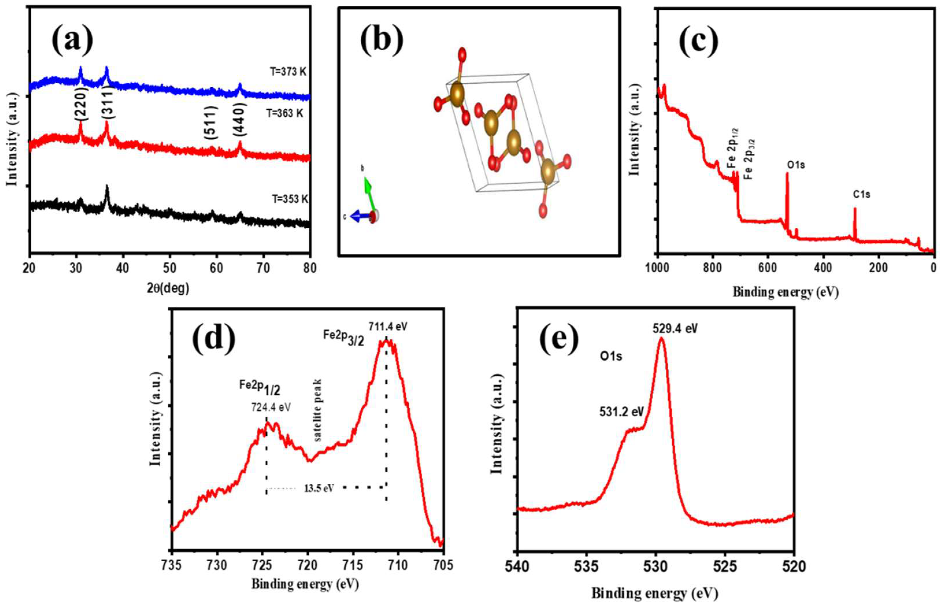
Figure 2.
(a–c) SEM images of S1, (d–f) S2, and (g–i) S3 thin films at different magnifications.
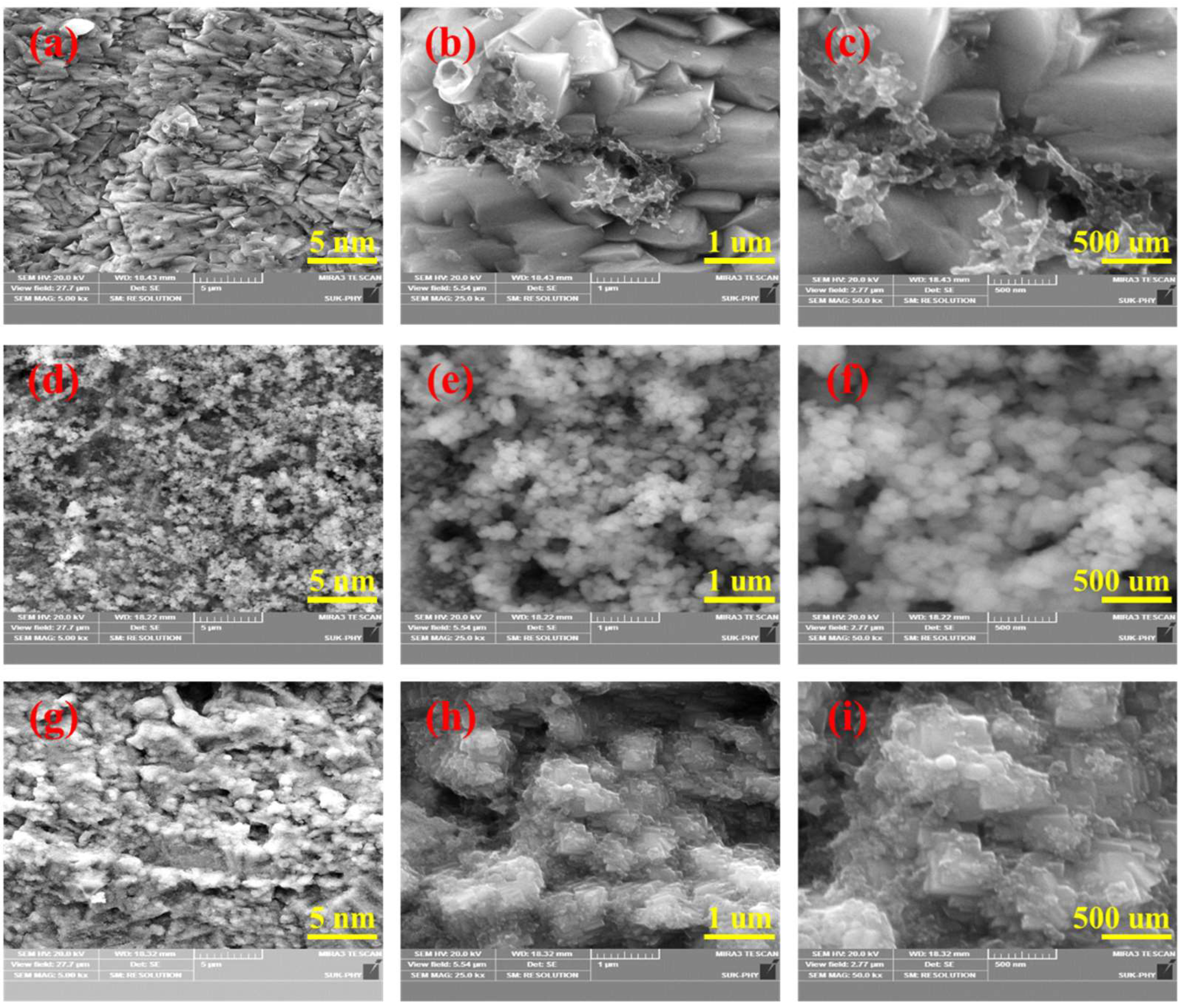
Figure 3.
(a,b) TEM images of α-Fe2O3.

Figure 4.
CV study for (a) S1, S2, and S3 samples, and (b) different scan rates; (c) GCD curves at different current densities; (d) plot of specific capacitance vs. current density; (e) plot of capacity retention vs. cycle number and inset shows the stability study at 5000 CV cycles for the α-Fe2O3 thin film.
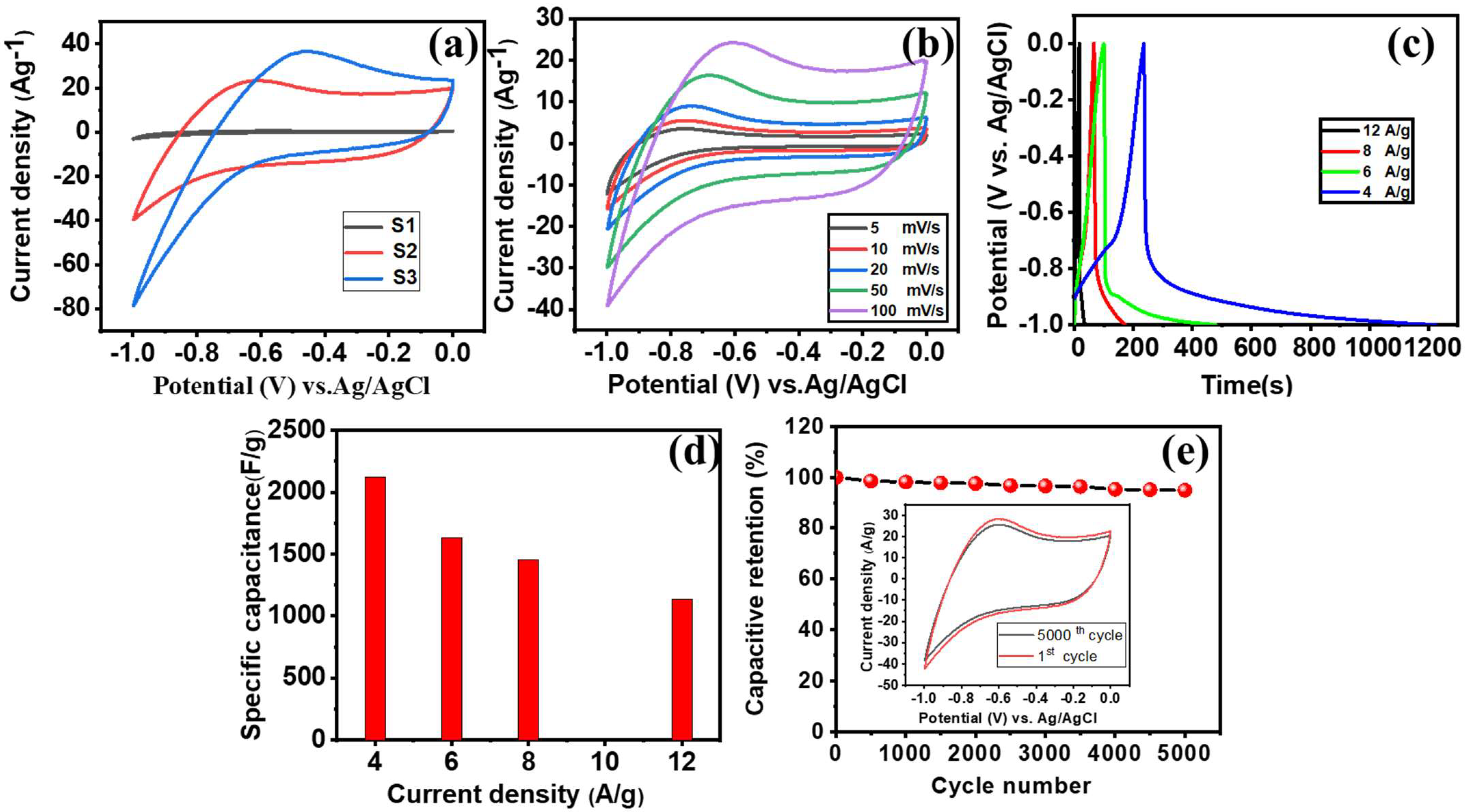
Figure 5.
(a) XRD pattern, (b) SEM images, and (c,d) TEM images for the Co3O4 thin film.
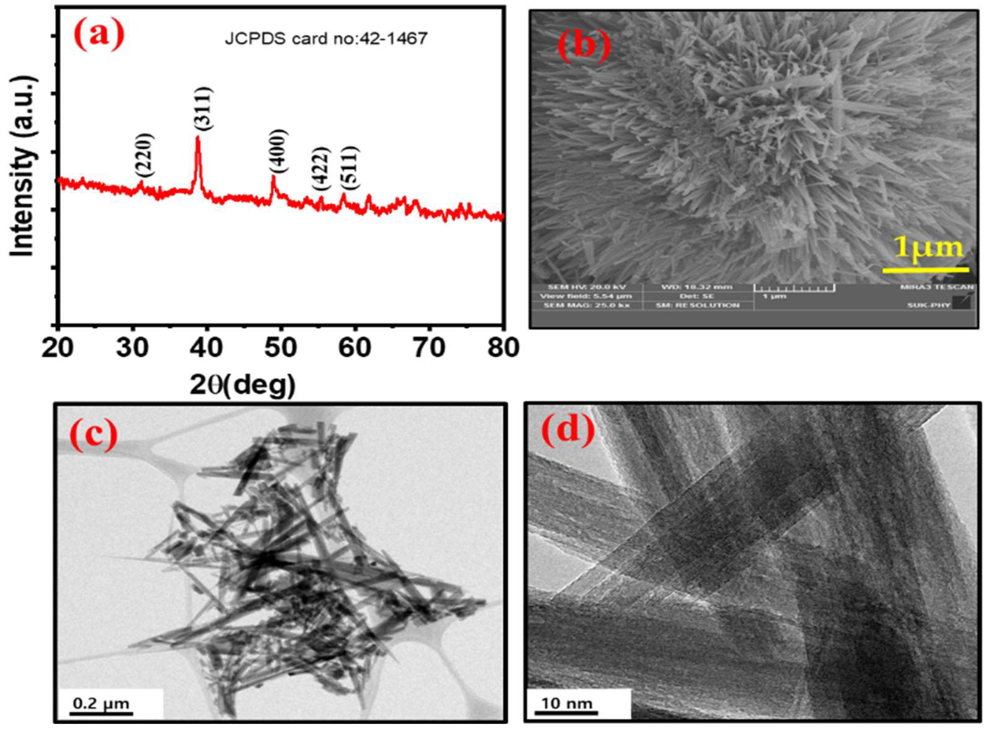
Figure 6.
(a) CV curves at different scan rates, (b) GCD curves at different current densities, (c) plot of specific capacitance vs. current density, (d) plot of capacity retention vs. cycle number, and the inset shows the stability study at 5000 CV cycles for the Co3O4-NF thin film.
Figure 6.
(a) CV curves at different scan rates, (b) GCD curves at different current densities, (c) plot of specific capacitance vs. current density, (d) plot of capacity retention vs. cycle number, and the inset shows the stability study at 5000 CV cycles for the Co3O4-NF thin film.
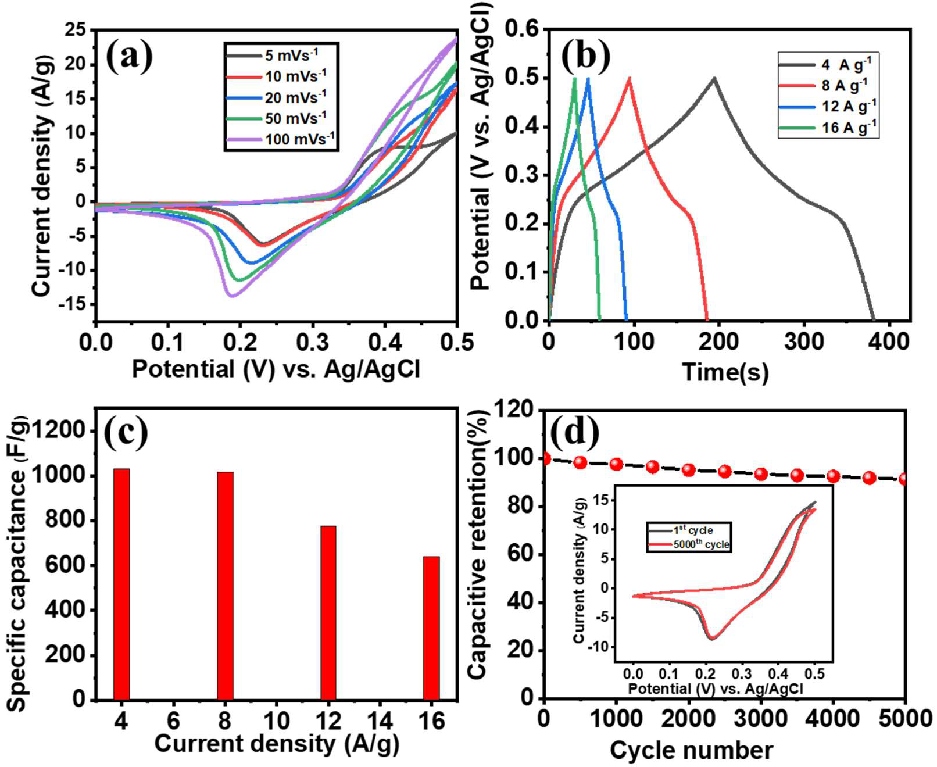
Figure 7.
(a) Schematic of the supercapacitor device, (b) CV curves at different scan rates for the Co3O4-NF//α-Fe2O3-NF ASC device, (c) variation in specific capacitance at different scan rates for the Co3O4-NF//α-Fe2O3-NF ASC device.
Figure 7.
(a) Schematic of the supercapacitor device, (b) CV curves at different scan rates for the Co3O4-NF//α-Fe2O3-NF ASC device, (c) variation in specific capacitance at different scan rates for the Co3O4-NF//α-Fe2O3-NF ASC device.

Figure 8.
(a) GCD curves, (b) variation in specific capacitance at different current densities, (c) capacitive retention study, and inset show stability study, (d) Nyquist plot, and the inset shows the high-frequency region for the Co3O4-NF//α-Fe2O3-NF ASC device.
Figure 8.
(a) GCD curves, (b) variation in specific capacitance at different current densities, (c) capacitive retention study, and inset show stability study, (d) Nyquist plot, and the inset shows the high-frequency region for the Co3O4-NF//α-Fe2O3-NF ASC device.
Publisher’s Note: MDPI stays neutral with regard to jurisdictional claims in published maps and institutional affiliations. |
© 2022 by the authors. Licensee MDPI, Basel, Switzerland. This article is an open access article distributed under the terms and conditions of the Creative Commons Attribution (CC BY) license (https://creativecommons.org/licenses/by/4.0/).
Share and Cite
MDPI and ACS Style
Yadav, A.A.; Hunge, Y.M.; Ko, S.; Kang, S.-W. Chemically Synthesized Iron-Oxide-Based Pure Negative Electrode for Solid-State Asymmetric Supercapacitor Devices. Materials 2022, 15, 6133. https://doi.org/10.3390/ma15176133
AMA Style
Yadav AA, Hunge YM, Ko S, Kang S-W. Chemically Synthesized Iron-Oxide-Based Pure Negative Electrode for Solid-State Asymmetric Supercapacitor Devices. Materials. 2022; 15(17):6133. https://doi.org/10.3390/ma15176133
Chicago/Turabian StyleYadav, A. A., Y. M. Hunge, Seongjun Ko, and Seok-Won Kang. 2022. "Chemically Synthesized Iron-Oxide-Based Pure Negative Electrode for Solid-State Asymmetric Supercapacitor Devices" Materials 15, no. 17: 6133. https://doi.org/10.3390/ma15176133
Note that from the first issue of 2016, this journal uses article numbers instead of page numbers. See further details here.