
Integration of Hot Isostatic Pressing and Heat Treatment for Advanced Modified γ-TiAl TNM Alloys

 , , , and
Abstract
:1. Introduction
2. Materials and Methods
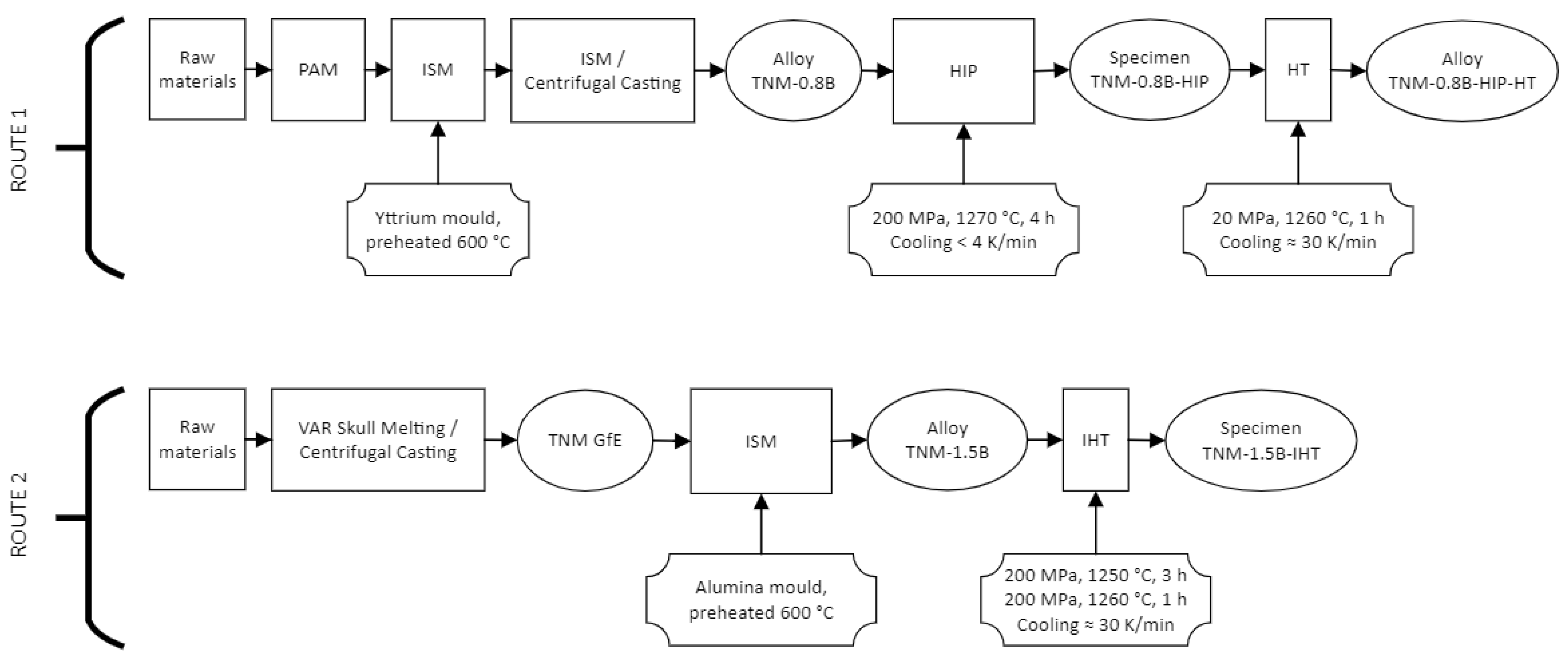
2.1. Alloy Manufacturing and Application of Thermomechanical Processes
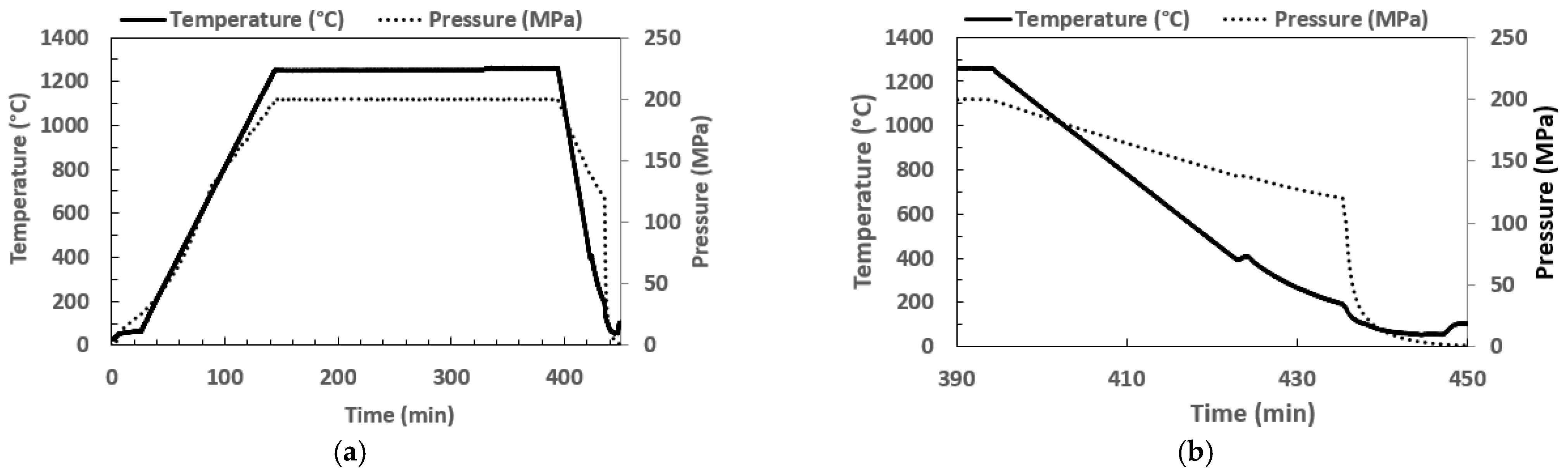
2.2. Insights into the IHT Process
2.3. Creep and Mechanical Testing
2.4. Microstructural Evaluation
3. Results
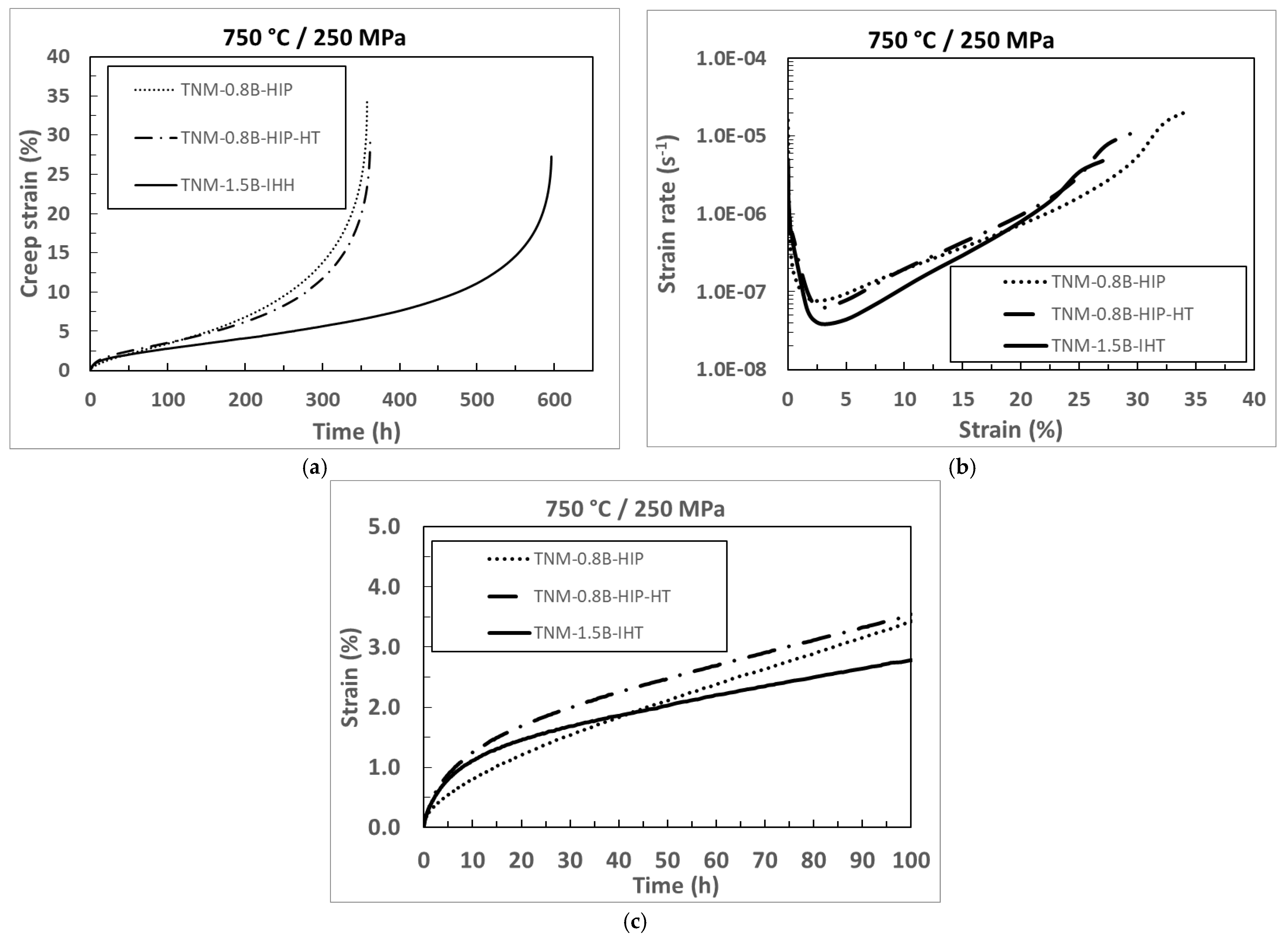
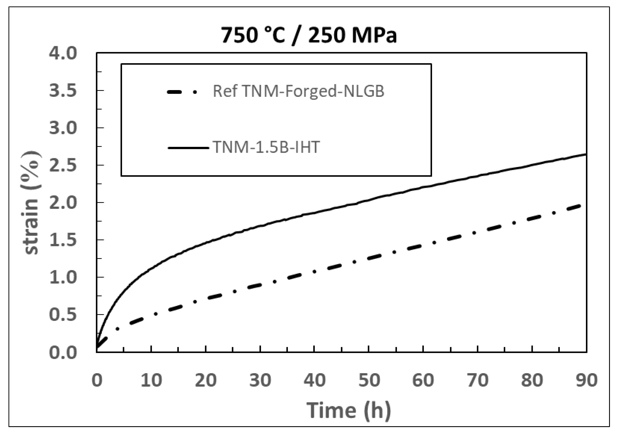
3.1. Creep Test
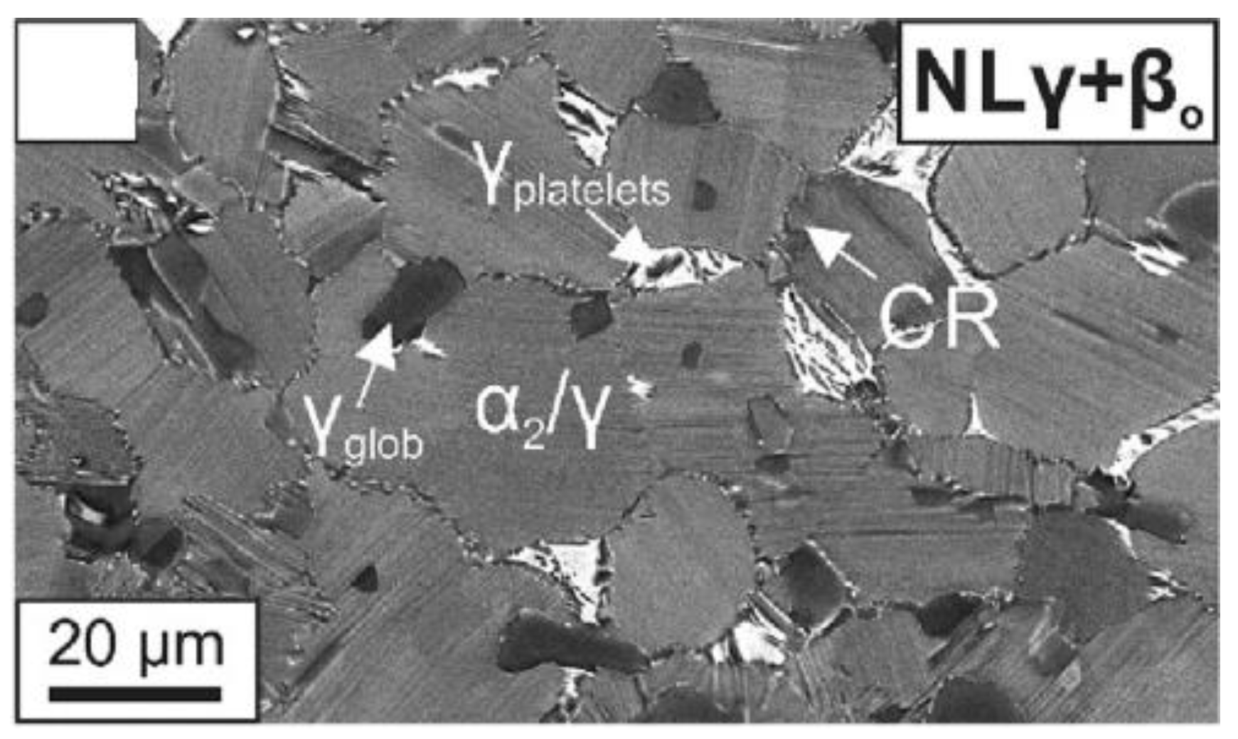
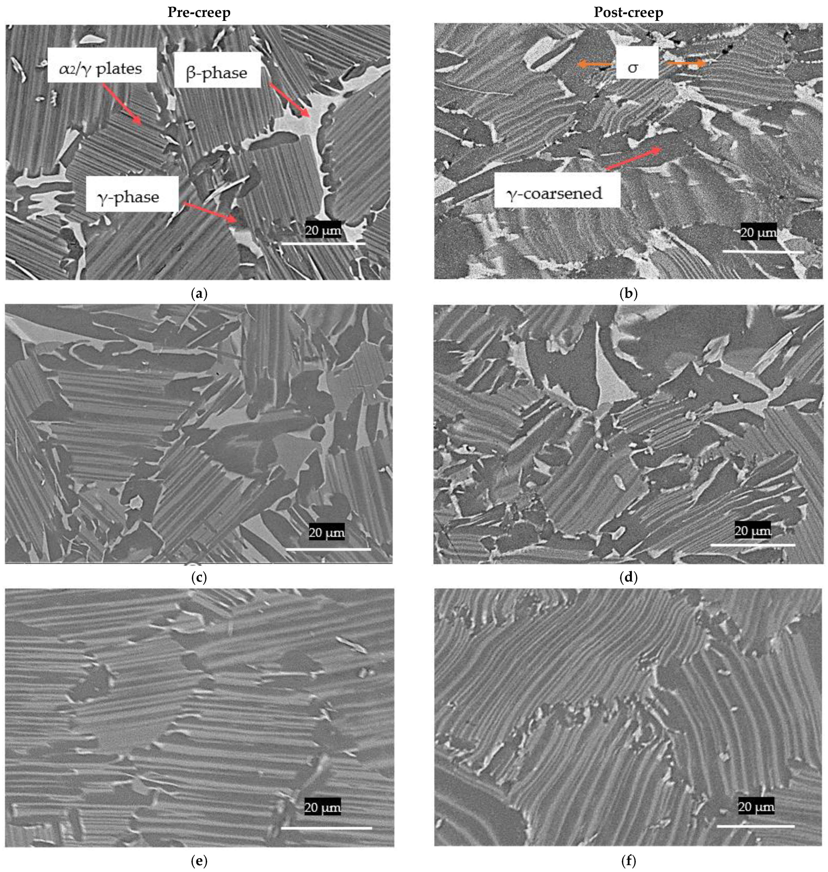
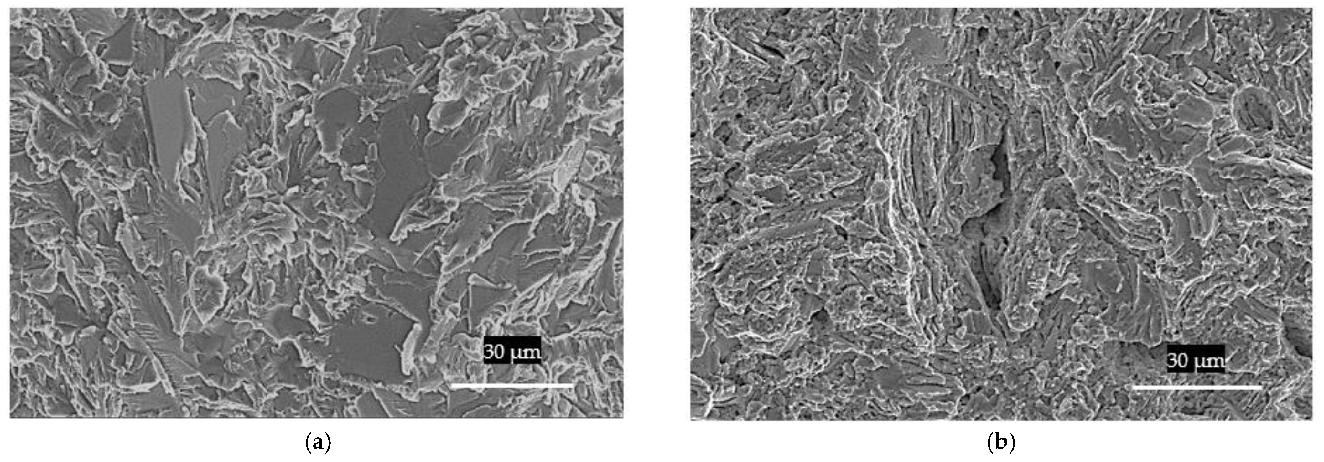
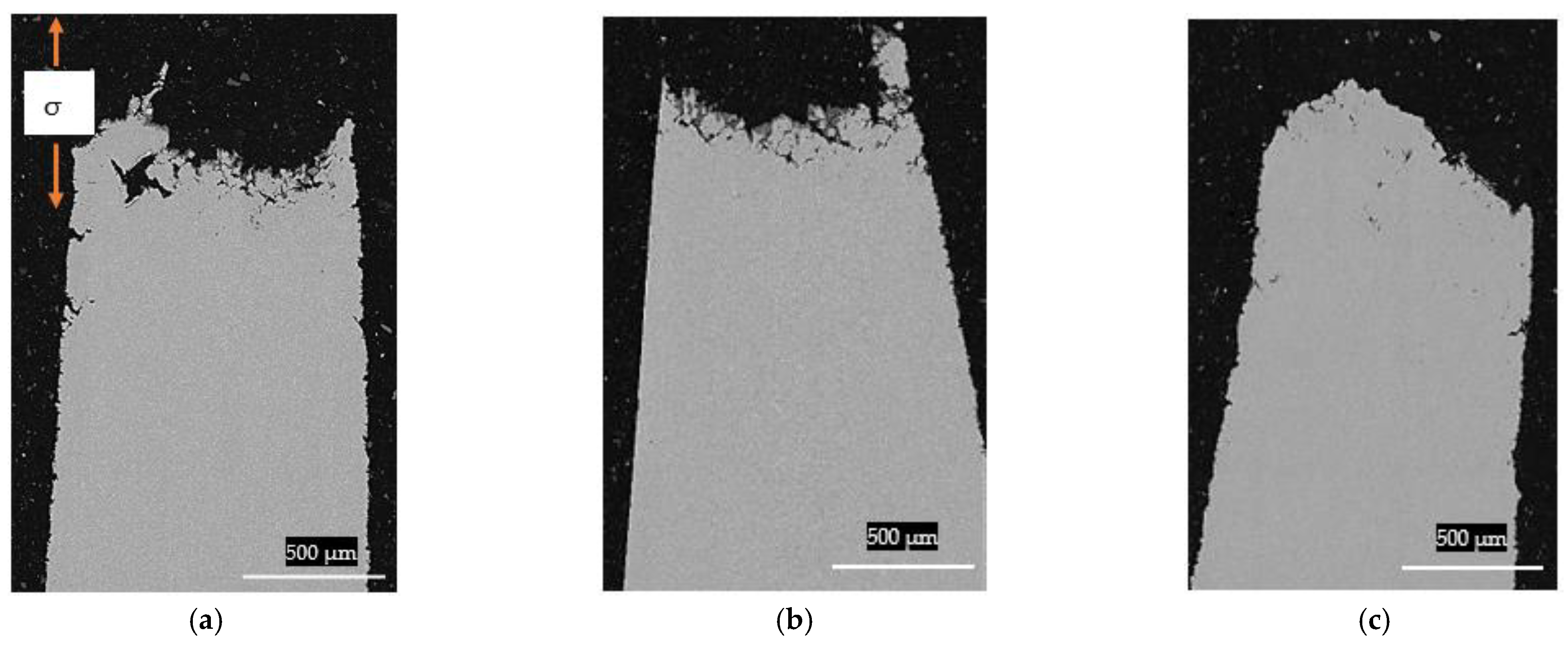
3.2. Microstructure Evolution during Creep
4. Discussion
Comparison between Conventional Forging Route and Cast/IHT Process
5. Conclusions
- Creep tests reveal that the novel modified TNM-1.5B-IHT alloy exhibits a slower accumulation of creep strain, a lower minimum creep rate εmin, 4.8 × 10⁻⁸ s−1, and a rupture time that exceeds that of the other tested materials by a factor of 1.5.
- TNM-1.5B-IHT presents a XDL microstructure composed of an average lamellar colony size of 55 µm and an average lamellar spacing of 0.6 µm, while the amount of β0-phase dropped to values below 0.5%. This in conjunction with reduced porosity accounts for the good resistance of this microstructure during creep.
- The modified TNM-1.5B-IHT demonstrates the potential of the effect of chemical composition and casting/IHT manufacturing route to reduce processing time and costs in comparison to conventional forged processes, while achieving similar creep behaviour.
Author Contributions
Funding
Acknowledgments
Conflicts of Interest
References
- Appel, F.; Paul, J.; Oehring, M. Gamma Titanium Aluminide Alloys; Wiley: Weinheim, Germany, 2014; Volume 1. [Google Scholar]
- Sibum, H.; Güther, V.; Roidl, O.; Habashi, F.; Wolf, H.U.; Siemers, C. Titanium, Titanium Alloys, and Titanium Compounds. In Ullmann’s Encyclopedia of Industrial Chemistry; Wiley: Hoboken, NJ, USA, 2017; Volume 37, pp. 1–35. [Google Scholar]
- Kim, Y.W.; Kim, S.L. Advances in gammalloy materials–processes–application technology: Successes, dilemmas and future. JOM 2018, 70, 553–560. [Google Scholar] [CrossRef] [Green Version]
- Habel, U.; Heutling, F.; Kunze, C.; Smarsly, W.; Das, G.; Clemens, H. Forged Intermetallic γ-TiAl Based Alloy Low Pressure Turbine Blade in the Geared Turbofan. In Proceedings of the 13th World Conference on Titanium, San Diego, CA, USA, 15–20 August 2015; pp. 1223–1227. [Google Scholar]
- Clemens, H.; Wallgram, W.; Kremmer, S.; Güther, V.; Otto, A.; Bartels, A. Design of novel β-solidifying TiAl alloys with adjustable β/B2-phase fraction and excellent hot-workability. Adv. Eng. Mater. 2008, 10, 707–713. [Google Scholar] [CrossRef]
- Kastenhuber, M.; Klein, T.; Clemens, H.; Mayer, S. Intermetallics Tailoring microstructure and chemical composition of advanced γ-TiAl based alloys for improved creep resistance. Intermetallics 2018, 97, 27–33. [Google Scholar] [CrossRef]
- Schwaighofer, E.; Clemens, H.; Mayer, S.; Lindemann, J.; Klose, J.; Smarsly, W.; Güther, V. Microstructural design and mechanical properties of a cast and heat-treated intermetallic multi-phase γ-TiAl based alloy. Intermetallics 2014, 44, 128–140. [Google Scholar] [CrossRef]
- Li, M.; Xiao, S.; Chen, Y.; Xu, L.; Tian, J. The effect of boron addition on the deformation behavior and microstructure of β-solidify TiAl alloys. Mater. Charact. 2018, 145, 312–322. [Google Scholar] [CrossRef]
- Wu, X.; Hu, D.; Loretto, M.H. Alloy and process development of TiAl. J. Mater. Sci. 2004, 39, 3935–3940. [Google Scholar] [CrossRef]
- Li, M.; Xiao, S.; Chen, Y.; Xu, L.; Tian, J. The effect of boron addition on the high-temperature properties and microstructure evolution of high Nb containing TiAl alloys. Mater. Sci. Eng. A 2018, 733, 190–198. [Google Scholar] [CrossRef]
- Kastenhuber, M.B.; Rashkova, B.; Clemens, H.; Mayer, S. Enhancement of creep properties and microstructural stability of intermetallic β-solidifying γ-TiAl based alloys. Intermetallics 2015, 63, 19–26. [Google Scholar] [CrossRef]
- Clemens, H.; Smarsly, W.; Güther, V.; Mayer, S. Advanced Intermetallic Titanium Aluminides. In Proceedings of the 13th World Conference on Titanium, San Diego, CA, USA, 16–20 August 2015; pp. 1189–1200. [Google Scholar]
- Mayer, S.; Erdely, P.; Fischer, F.D.; Holec, D.; Kastenhuber, M.; Klein, T.; Clemens, H. Intermetallic β-Solidifying γ-TiAl Based Alloys—From Fundamental Research to Application. Adv. Eng. Mater. 2017, 19, 1600735. [Google Scholar] [CrossRef]
- Erdely, P.; Staron, P.; Maawad, E.; Schell, N.; Klose, J.; Clemens, H.; Mayer, S. Design and control of microstructure and texture by thermomechanical processing of a multi-phase TiAl alloy. Mater. Des. 2017, 131, 286–296. [Google Scholar] [CrossRef]
- Rittinghaus, S.K.; Hecht, U.; Werner, V.; Weisheit, A. Heat treatment of laser metal deposited TiAl TNM alloy. Intermetallics 2018, 95, 94–101. [Google Scholar] [CrossRef]
- Ahlfors, M.; Shipley, J.; Lopez-Galilea, I. Hot Isostatic Pressing for the Casting Industry; EICF (European Investment Casters’ Federation): Worcestershire, UK, 2019. [Google Scholar]
- Roncery, L.M.; Lopez-Galilea, I.; Ruttert, B.; Bürger, D.; Wollgramm, P.; Eggeler, G.; Theisen, W. On the Effect of Hot Isostatic Pressing on the Creep Life of a Single Crystal Superalloys. Adv. Eng. Mater. 2016, 18, 1381–1387. [Google Scholar] [CrossRef]
- Meid, C.; Dennstedt, A.; Ramsperger, M.; Pistor, J.; Ruttert, B.; Lopez-Galilea, I.; Theisen, W.; Körner, C.; Bartsch, M. Effect of heat treatment on the high temperature fatigue life of single crystalline nickel base superalloy additively manufactured by means of selective electron beam melting. Scr. Mater. 2019, 168, 124–128. [Google Scholar] [CrossRef]
- Ruttert, B.; Ramsperger, M.; Mujica Roncery, L.; Lopez-Galilea, I.; Körner, C.; Theisen, W. Impact of hot isostatic pressing on microstructures of CMSX-4 Ni-base superalloy fabricated by selective electron beam melting. Mater. Des. 2016, 110, 720–727. [Google Scholar] [CrossRef]
- Chatterjee, A.; Mecking, H.; Arzt, E.; Clemens, H. Creep behavior of g-TiAl sheet material with differently spaced fully lamellar microstructures. Mater. Sci. Eng. A 2002, 331, 840–846. [Google Scholar] [CrossRef]
- Du, X.; Zhu, J.; Kim, Y. Microstructural characterization of creep cavitation in a fully-lamellar TiAl alloy. Intermetallics 2001, 9, 137–146. [Google Scholar] [CrossRef]
- Chen, R.; Wang, Q.; Yang, Y.; Guo, J.; Su, Y.; Ding, H.; Fu, H. Brittle-ductile transition during creep in nearly and fully lamellar high-Nb TiAl alloys. Intermetallics 2018, 93, 47–54. [Google Scholar] [CrossRef]
- Bernal, D.; Chamorro, X.; Hurtado, I.; Madariaga, I. Evolution of lamellar microstructures in a cast TNM alloy modified with boron through single-step heat treatments. Intermetallics 2020, 124, 106842. [Google Scholar] [CrossRef]
- Güther, V.; Allen, M.; Klose, J.; Clemens, H. Metallurgical processing of titanium aluminides on industrial scale. Intermetallics 2018, 103, 12–22. [Google Scholar] [CrossRef]
- Bernal, D.; Chamorro, X.; Hurtado, I.; Madariaga, I. Effect of Boron Content and Cooling Rate on the Microstructure and Boride Formation of β-Solidifying γ-TiAl TNM Alloy. Metals 2020, 10, 698. [Google Scholar] [CrossRef]
- Wollgramm, P.; Bürger, D.; Parsa, A.B.; Neuking, K.; Eggeler, G. The Effect of Stress, Temperature and Loading Direction on the Creep Behaviour of Ni-Base Single Crystal Superalloy Miniature Tensile Specimens. Mater. High Temp. 2016, 33, 346–360. [Google Scholar] [CrossRef]
- Körner, C.; Ramsperger, M.; Meid, C.; Bürger, D.; Wollgramm, P.; Bartsch, M.; Eggeler, G. Microstructure and Mechanical Properties of CMSX-4 Single Crystals Prepared by Additive Manufacturing. Metall. Mater. Trans. A 2018, 49, 3781–3792. [Google Scholar] [CrossRef] [Green Version]
- Niu, H.Z.; Chen, Y.Y.; Xiao, S.L.; Xu, L.J. Microstructure evolution and mechanical properties of a novel beta γ-TiAl alloy. Intermetallics 2012, 31, 225–231. [Google Scholar] [CrossRef]


| Alloy | Ti | Al | Nb | Mo | B |
|---|---|---|---|---|---|
| TNM-0.8B | Balanced | 43.5 | 3.5 | 1 | 0.8 |
| TNM-1.5B | Balanced | 42.5 | 3.5 | 1 | 1.5 |
| TNM-Forged-NLGB | Balanced | 43.7 | 4.1 | 1 | 0.1 |
| Sample | Casting Route | HIP | HT |
|---|---|---|---|
| TNM-0.8B-HIP | PAM + ISM | 200 MPa Ar, 1270 °C, 4 h, slow cooling | None |
| TNM-0.8B-HIP-HT | PAM + ISM | 200 MPa Ar, 1270 °C, 4 h, slow cooling | 1260 °C, 1 h, 20 MPa Ar, cooling at 30 K/min |
| TNM-1.5B-IHT | VAR + ISM | Integrated: 1250 °C, 3h, 200 MPa Ar and 1260 °C, 1 h, 200 MPa Ar, 30 K/min | |
| Sample | State | % Area of β0-Phase | Colony Size [µm] | Lamellar Spacing [µm] | εmin [s−1] | Time to Creep Rupture [h] |
|---|---|---|---|---|---|---|
| TNM-0.8B-HIP | Pre-creep | 7.6 | 56 | 0.8 | - | - |
| Post-creep | 10.4 | 53 | 0.9 | 7.8 × 10⁻⁸ | 357 | |
| TNM-0.8B-HIP-HT | Pre-creep | 3.9 | 51 | 0.6 | - | - |
| Post-creep | 6.9 | 65 | 0.8 | 6.3 × 10⁻⁸ | 362 | |
| TNM-1.5B-IHT | Pre-creep | 0.3 | 58 | 0.6 | - | - |
| Post-creep | 0.5 | 51 | 0.7 | 4.8 × 10⁻⁸ | 574 |
| Sample | % Area of β0-Phase | Colony Size [µm] | Lamellar Spacing [µm] | εmin [s−1] |
|---|---|---|---|---|
| TNM-1.5B-IHT | 0.5 | 51 | 0.7 | 4.8 × 10⁻⁸ |
| TNM-Forged-NLGB | 1 | 15 | 0.02 | 4.9 × 10⁻⁸ |
Publisher’s Note: MDPI stays neutral with regard to jurisdictional claims in published maps and institutional affiliations. |
© 2022 by the authors. Licensee MDPI, Basel, Switzerland. This article is an open access article distributed under the terms and conditions of the Creative Commons Attribution (CC BY) license (https://creativecommons.org/licenses/by/4.0/).
Share and Cite
Bernal, D.; Chamorro, X.; Hurtado, I.; Lopez-Galilea, I.; Bürger, D.; Weber, S.; Madariaga, I. Integration of Hot Isostatic Pressing and Heat Treatment for Advanced Modified γ-TiAl TNM Alloys. Materials 2022, 15, 4211. https://doi.org/10.3390/ma15124211
Bernal D, Chamorro X, Hurtado I, Lopez-Galilea I, Bürger D, Weber S, Madariaga I. Integration of Hot Isostatic Pressing and Heat Treatment for Advanced Modified γ-TiAl TNM Alloys. Materials. 2022; 15(12):4211. https://doi.org/10.3390/ma15124211
Chicago/Turabian StyleBernal, Daniel, Xabier Chamorro, Iñaki Hurtado, Inmaculada Lopez-Galilea, David Bürger, Sebastian Weber, and Iñaki Madariaga. 2022. "Integration of Hot Isostatic Pressing and Heat Treatment for Advanced Modified γ-TiAl TNM Alloys" Materials 15, no. 12: 4211. https://doi.org/10.3390/ma15124211