Investigation of Damage Reduction When Dry-Drilling Aramid Fiber-Reinforced Plastics Based on a Three-Point Step Drill


Abstract
:1. Introduction
2. Drilling Model of AFRP
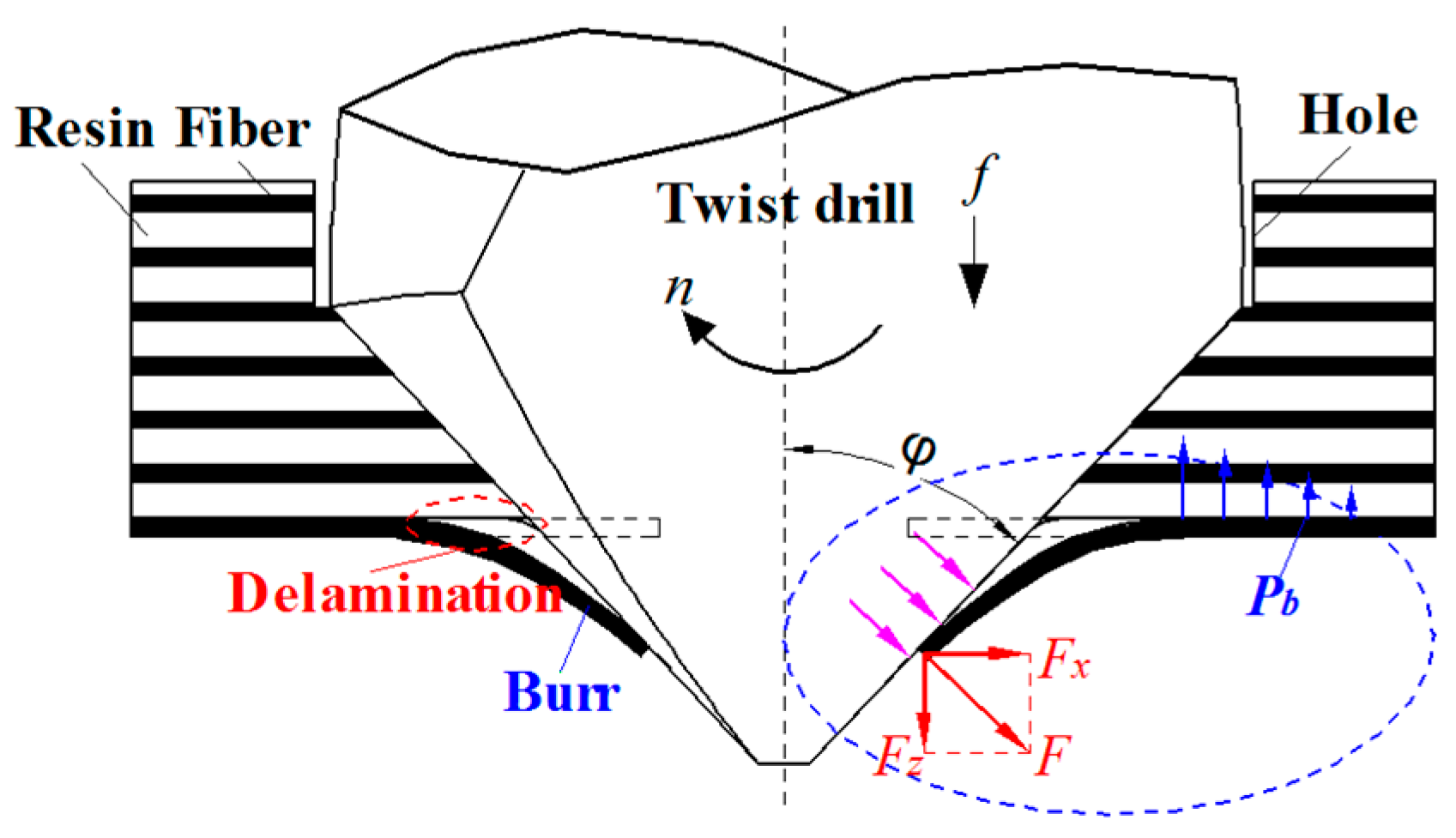
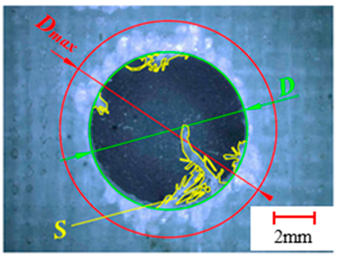
2.1. Drill-Exit Damages Analysis
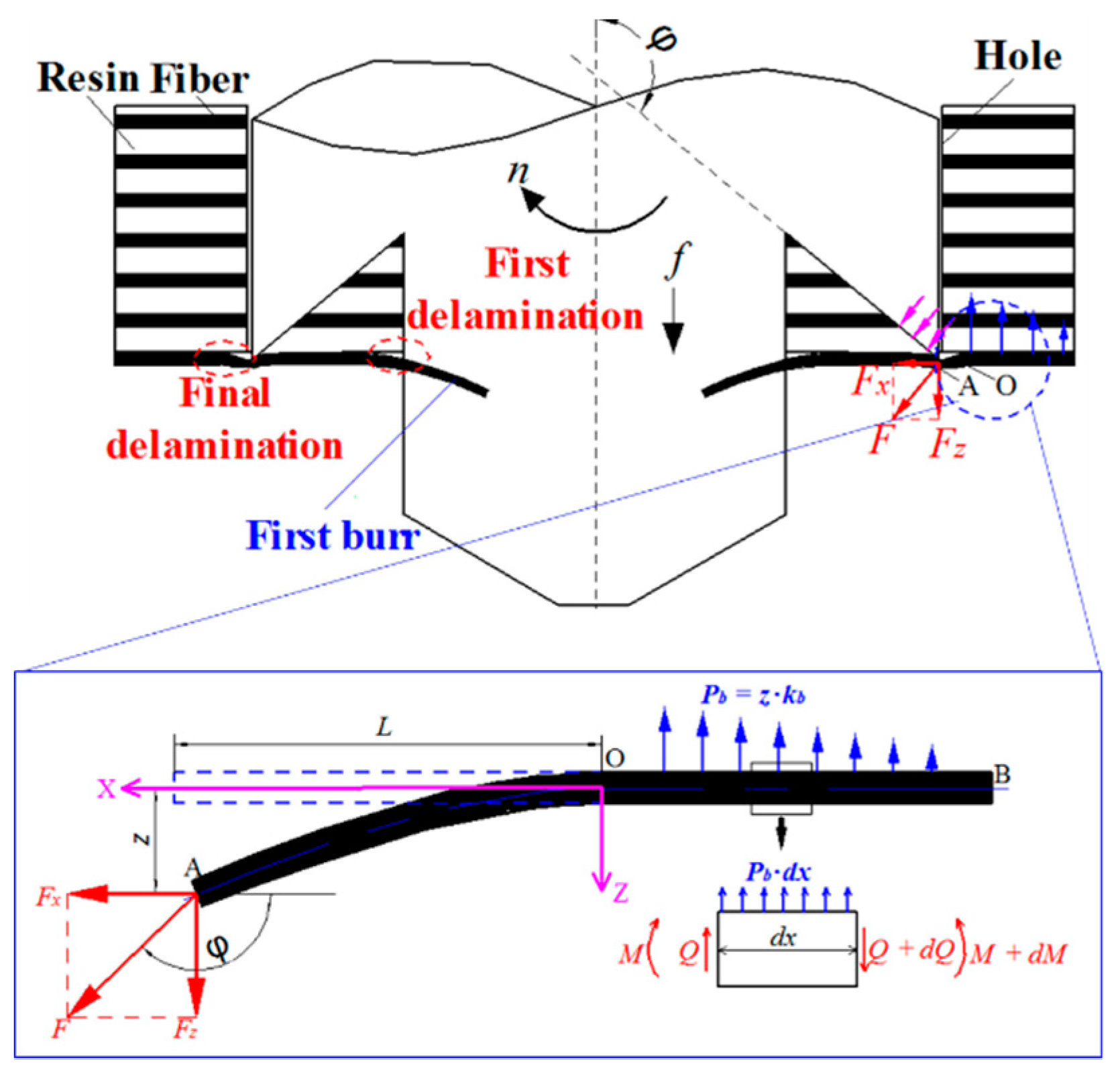
2.2. Fiber Deformation Calculation
3. Low-Damage Drill Design and Analysis
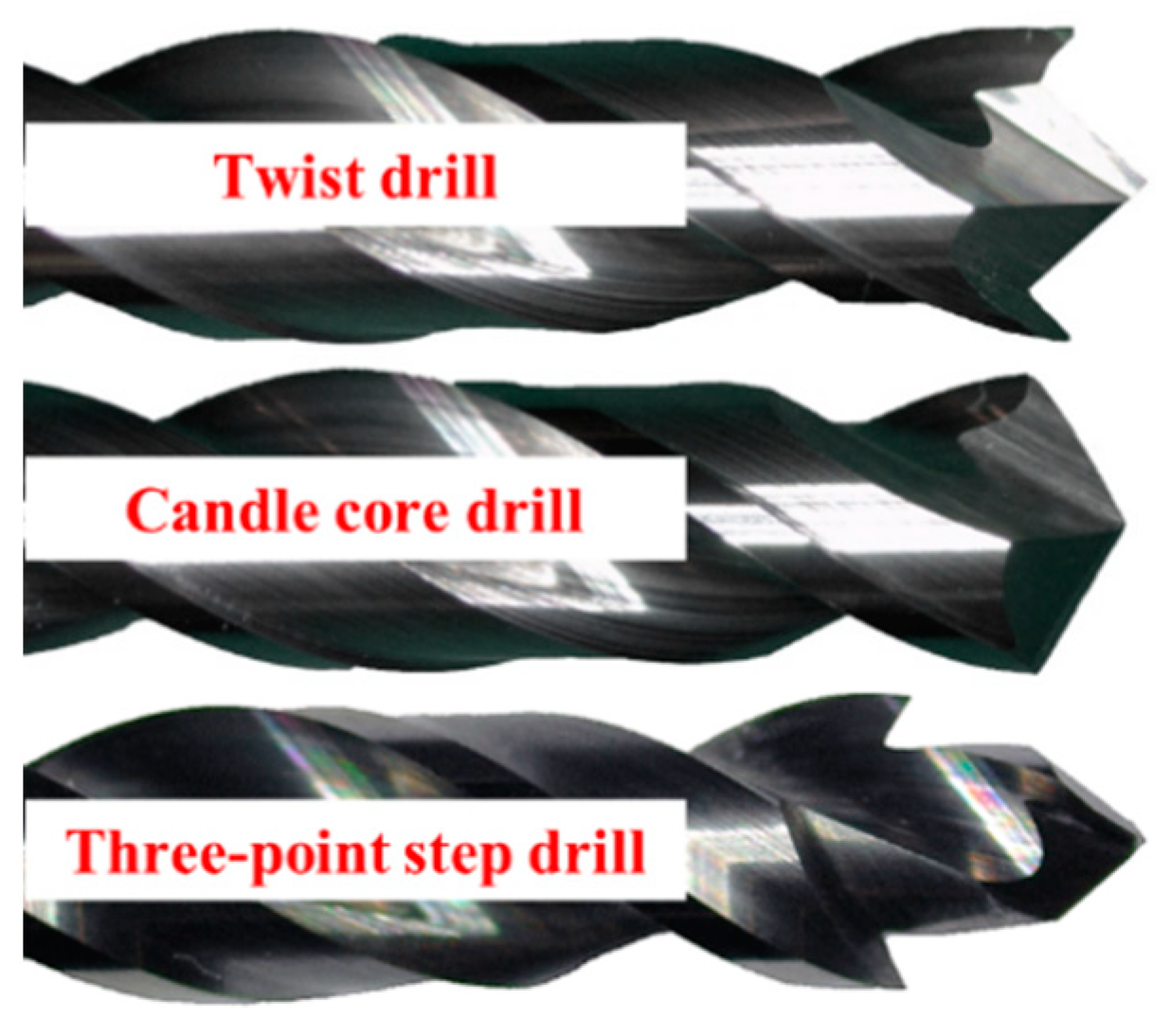
3.1. Design of the New Drill
3.2. Drilling Mechanism of the Three-Point Step Drill
4. Experimental Verification
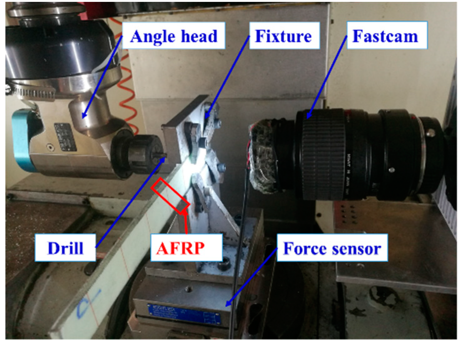
4.1. Experimental Details
4.2. Experimental Results and Discussion
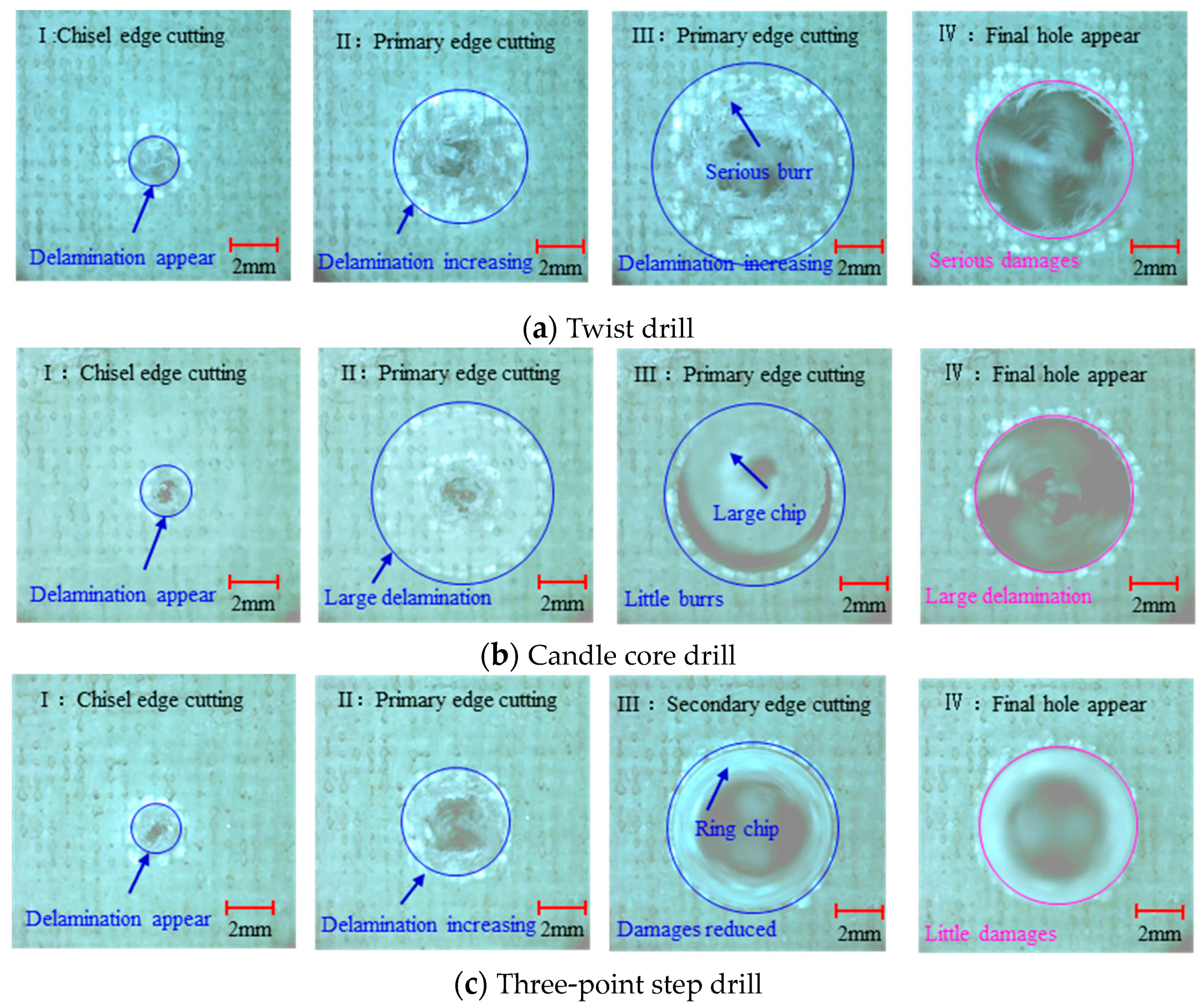
4.2.1. Drilling Process Results
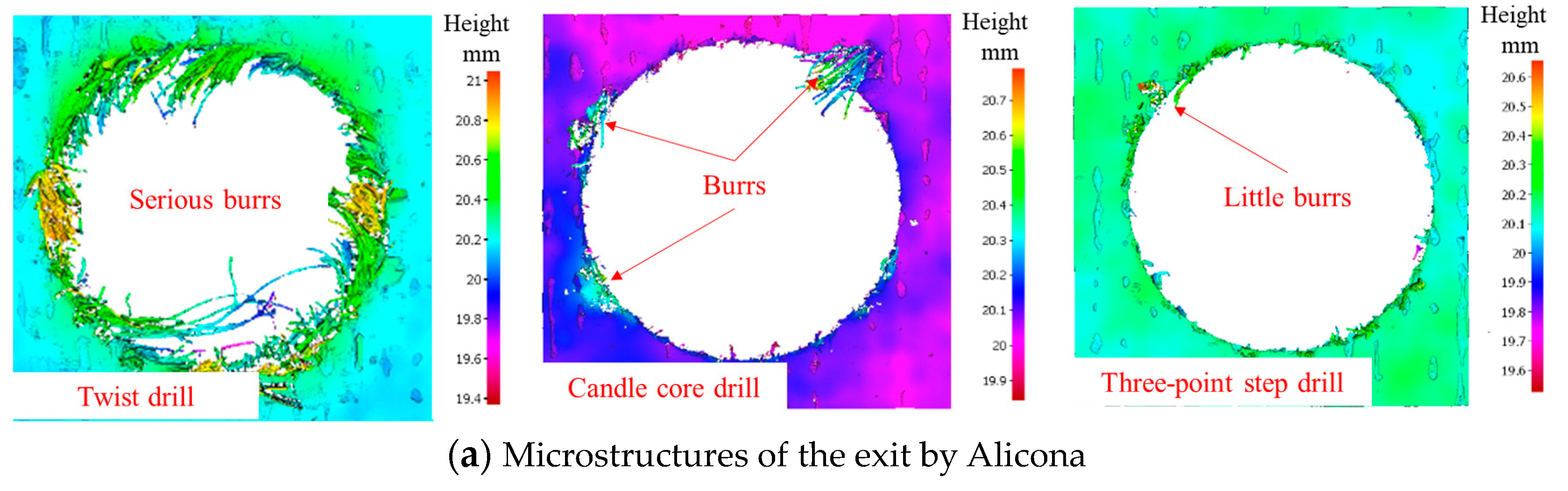
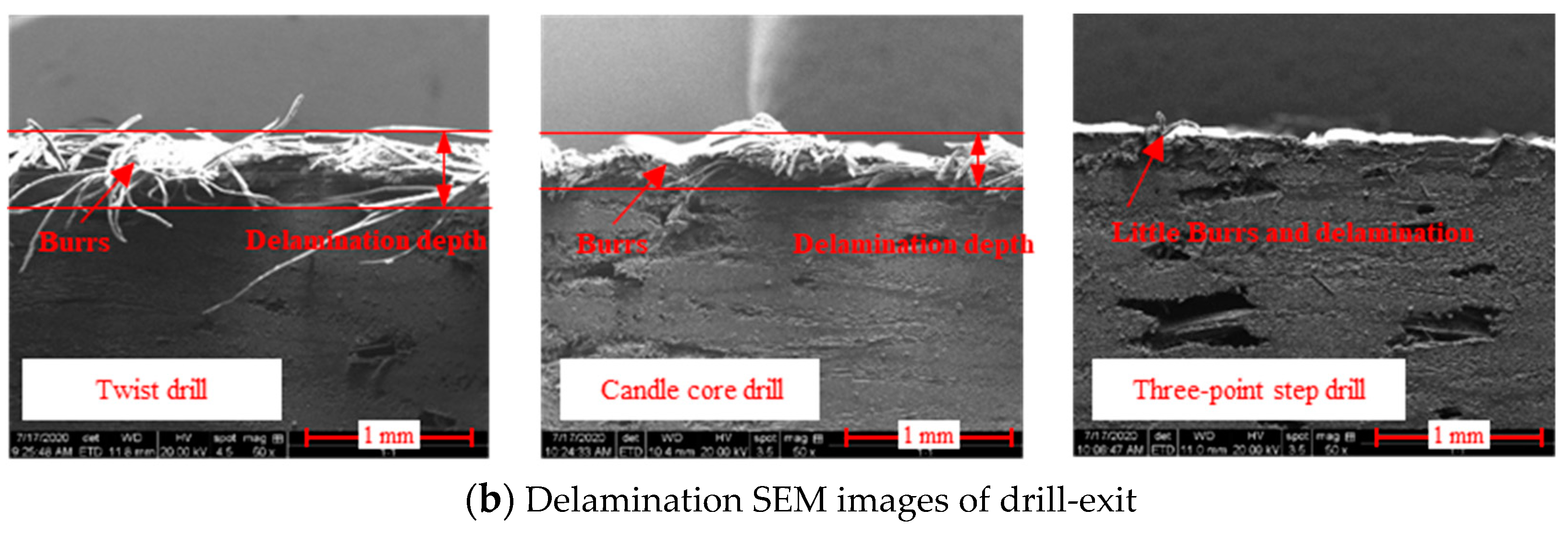
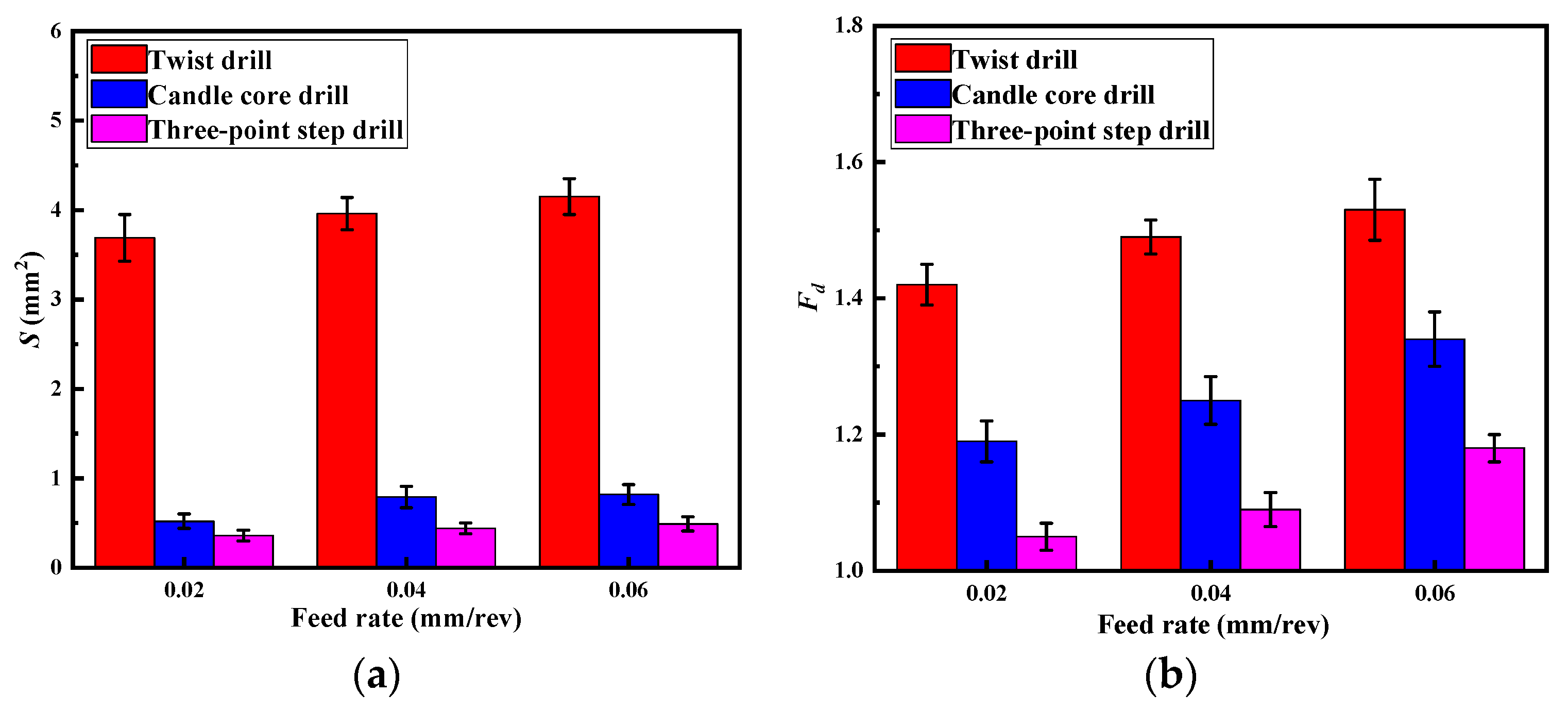
4.2.2. Quality of Drill-Exit
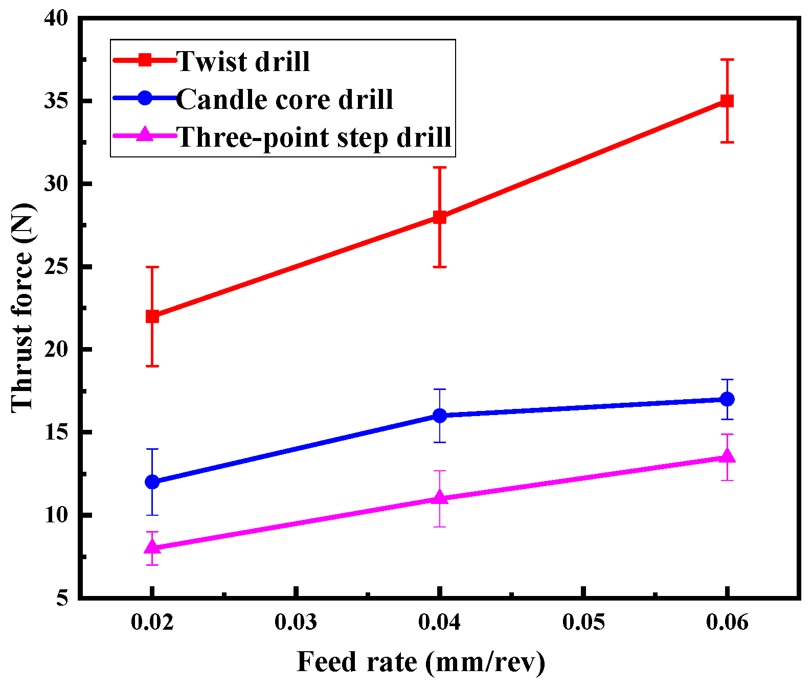
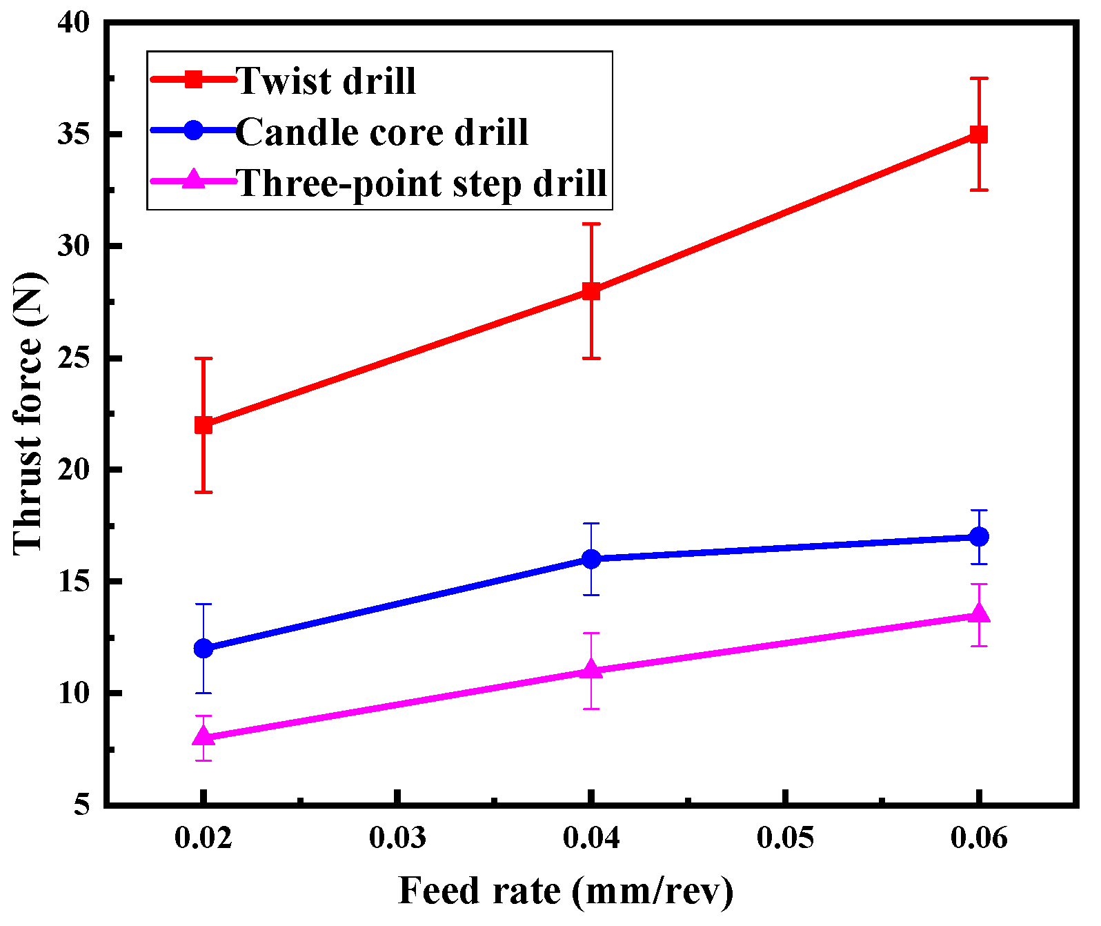
4.2.3. Thrust Forces
5. Conclusions
- A two-dimensional cutting model of drill-exit fibers was established successfully for analyzing the fiber deformation. The thrust force and radial cutting force of the edge on the fiber have important influences on the deformation of the exit fiber, and reducing the thrust force and changing the direction of the radial cutting force on the fiber to point into the hole can effectively reduce the deflection of the exit fiber.
- The three-point edge drill with a step structure can cut the material step-by-step, and three points can cut the aramid fiber effectively; the thrust force was reduced, leading to delamination being decreased and fewer, smaller burrs were cut by the three-point structure.
- Comparative milling experiments’ results proved that the three-point step drill can reduce the delamination and burrs at the same time, compared to the twist drill and candle core drill. The feed rate increase led to a drilling delamination increase, but had little effect on the burr damage. The three-point step drill with a small feed rate effectively removed the burrs and avoided delamination, making it a complete low-damage drilling method for AFRP.
Author Contributions
Funding
Acknowledgments
Conflicts of Interest
References
- Li, Z.; Cheng, X.; He, S.; Shi, X.; Gong, L.; Li, Z. Aramid fibers reinforced silica aerogel composites with low thermal conductivity and improved mechanical performance. Compos. Part A Appl. Sci. Manuf. 2016, 84, 316–325. [Google Scholar] [CrossRef]
- Homae, T.; Shimizu, T.; Fukasawa, K.; Masamura, O. Hypervelocity Planar Plate Impact Experiments of Aramid Fiber-reinforced Plastics. J. Reinf. Plast. Compos. 2006, 25, 1215–1221. [Google Scholar] [CrossRef]
- Okhawilai, M.; Parnklang, T.; Mora, P.; Hiziroglu, S.; Rimdusit, S. The energy absorption enhancement in aramid fiber-reinforced poly(benzoxazine-co-urethane) composite armors under ballistic impacts. J. Reinf. Plast. Compos. 2018, 38, 133–146. [Google Scholar] [CrossRef]
- Dharan, C.; Won, M. Machining parameters for an intelligent machining system for composite laminates. Int. J. Mach. Tools Manuf. 2000, 40, 415–426. [Google Scholar] [CrossRef]
- Liu, S.; Yang, T.; Liu, C.; Du, Y. Comprehensive investigation of cutting mechanisms and hole quality in dry drilling woven aramid fibre–reinforced plastic with typical tools. Proc. Inst. Mech. Eng. Part B J. Eng. Manuf. 2019, 233, 2471–2491. [Google Scholar] [CrossRef]
- Masoud, F.; Sapuan, S.; Ariffin, M.M.; Nukman, Y.; Bayraktar, E. Cutting Processes of Natural Fiber-Reinforced Polymer Composites. Polymers 2020, 12, 1332. [Google Scholar] [CrossRef]
- Abrão, A.; Faria, P.; Rubio, J.C.; Reis, P.; Davim, J.P. Drilling of fiber reinforced plastics: A review. J. Mater. Process. Technol. 2007, 186, 1–7. [Google Scholar] [CrossRef]
- Sun, D.; Lemoine, P.; Keys, D.; Doyle, P.; Malinov, S.; Zhao, Q.; Qin, X.; Jin, Y. Hole-making processes and their impacts on the microstructure and fatigue response of aircraft alloys. Int. J. Adv. Manuf. Technol. 2016, 94, 1719–1726. [Google Scholar] [CrossRef] [Green Version]
- Nor, F.M.; Lim, J.Y.; Tamin, M.N.; Lee, H.Y.; Kurniawan, D. Effects of Starter Defect on Energy Release Rate of Three-Point End-Notch Flexure Tested Unidirectional Carbon Fiber Reinforced Polymer Composite. Polymers 2020, 12, 904. [Google Scholar] [CrossRef] [Green Version]
- Zhang, L.C.; Zhang, H.J.; Wang, X.M. A Force Prediction Model for Cutting Unidirectional Fibre-Reinforced Plastics. Mach. Sci. Technol. 2001, 5, 293–305. [Google Scholar] [CrossRef]
- Pwu, H.Y.; Hocheng, H. Chip Formation Model of Cutting Fiber-Reinforced Plastics Perpendicular to Fiber Axis. J. Manuf. Sci. Eng. 1998, 120, 192–196. [Google Scholar] [CrossRef]
- Xu, W.; Zhang, L. Mechanics of fibre deformation and fracture in vibration-assisted cutting of unidirectional fibre-reinforced polymer composites. Int. J. Mach. Tools Manuf. 2016, 103, 40–52. [Google Scholar] [CrossRef]
- Li, H.; Qin, X.; He, G.; Price, M.S.T.; Jin, Y.; Sun, D. An energy based force prediction method for UD-CFRP orthogonal machining. Compos. Struct. 2017, 159, 34–43. [Google Scholar] [CrossRef] [Green Version]
- Jia, Z.; Fu, R.; Niu, B.; Qian, B.; Bai, Y.; Wang, F. Novel drill structure for damage reduction in drilling CFRP composites. Int. J. Mach. Tools Manuf. 2016, 110, 55–65. [Google Scholar] [CrossRef]
- Su, F.; Zheng, L.; Sun, F.; Wang, Z.; Deng, Z.; Qiu, X. Novel drill bit based on the step-control scheme for reducing the CFRP delamination. J. Mater. Process. Technol. 2018, 262, 157–167. [Google Scholar] [CrossRef]
- Kim, S.-C.; Kim, J.-S.; Yoon, H.-J. Experimental and numerical investigations of mode I delamination behaviors of woven fabric composites with carbon, Kevlar and their hybrid fibers. Int. J. Precis. Eng. Manuf. 2011, 12, 321–329. [Google Scholar] [CrossRef]
- Wan, Y.; Chen, G.; Huang, Y.; Li, Q.; Zhou, F.; Xin, J.; Wang, Y. Characterization of three-dimensional braided carbon/Kevlar hybrid composites for orthopedic usage. Mater. Sci. Eng. A 2005, 398, 227–232. [Google Scholar] [CrossRef]
- Bunsell, A.R. The tensile and fatigue behaviour of Kevlar-49 (PRD-49) fibre. J. Mater. Sci. 1975, 10, 1300–1308. [Google Scholar] [CrossRef]
- Wang, F.; Yan, J.-B.; Zhao, M.; Wang, D.; Wang, X.-N.; Hao, J.-X. Surface damage reduction of dry milling carbon fiber reinforced plastic/polymer using left–right edge milling tool. J. Reinf. Plast. Compos. 2020, 39, 409–421. [Google Scholar] [CrossRef]
- Biermann, D.; Bathe, T.; Rautert, C. Core Drilling of Fiber Reinforced Materials using Abrasive Tools. Procedia CIRP 2017, 66, 175–180. [Google Scholar] [CrossRef]
- Wu, M.; Tong, X.; Wang, H.; Hua, L.; Chen, Y. Effect of Ultrasonic Vibration on Adhesive Bonding of CFRP/Al Alloy Joints Grafted with Silane Coupling Agent. Polymers 2020, 12, 947. [Google Scholar] [CrossRef] [PubMed]
- Liu, S.; Yang, T.; Liu, C.; Jin, Y.; Sun, D.; Shen, Y. Modelling and experimental validation on drilling delamination of aramid fiber reinforced plastic composites. Compos. Struct. 2020, 236, 111907. [Google Scholar] [CrossRef]
- Zheng, X.; Dong, D.; Huang, L.; Wang, X.; Chen, M. Investigation of tool wear mechanism and tool geometry optimization in drilling of PCB fixture hole. Circuit World 2013, 39, 195–203. [Google Scholar] [CrossRef]
- Shuaib, A.N.; Al-Sulaiman, F.A.; Hamid, F. Machinability of Kevlar® 49 Composite Laminates While Using Standard TiN Coated HSS Drills. Mach. Sci. Technol. 2004, 8, 449–467. [Google Scholar] [CrossRef]
- Veniali, F.; Di Ilio, A.; Tagliaferri, V. An Experimental Study of the Drilling of Aramid Composites. J. Energy Resour. Technol. 1995, 117, 271–278. [Google Scholar] [CrossRef]
- Iqbal, M.; Bahri, S.; Akram, A. Effect of cutting parameter on tool wear of HSS tool in drilling of Kevlar composite panel. In Proceedings of the IOP Conference Series: Materials Science and Engineering; IOP Publishing: Bristol, UK, 2019; p. 012078. [Google Scholar]
- Hao, J.; Wang, F.; Zhao, M.; Bai, Y.; Jia, Z. Drill bit with clip-edges based on the force control model for reducing the CFRP damage. J. Reinf. Plast. Compos. 2020. [Google Scholar] [CrossRef]
- Bishop, G.; Gindy, N. An investigation into the drilling of ballistic Kevlar composites. Compos. Manuf. 1990, 1, 155–159. [Google Scholar] [CrossRef]
- Bhattacharyya, D.; Horrigan, D. A study of hole drilling in Kevlar composites. Compos. Sci. Technol. 1998, 58, 267–283. [Google Scholar] [CrossRef]
- Lei, J.; Jing, Q. Performance Analysis of Drilling Test of Aramid Fiber Composite. In Proceedings of the IOP Conference Series: Materials Science and Engineering; IOP Publishing: Bristol, UK, 2019; Volume 616, p. 012017. [Google Scholar]
- Anarghya, A.; Harshith, D.; Rao, N.; Nayak, N.S.; Gurumurthy, B.; Abhishek, V.; Patil, I.G.S. Thrust and torque force analysis in the drilling of aramid fibre-reinforced composite laminates using RSM and MLPNN-GA. Heliyon 2018, 4, e00703. [Google Scholar] [CrossRef] [Green Version]
- Díaz-Álvarez, A.; Rodríguez-Millán, M.; Miguélez, M. Experimental analysis of drilling induced damage in aramid composites. Compos. Struct. 2018, 202, 1136–1144. [Google Scholar] [CrossRef]
- Gao, H.; Zhuang, Y.; Wang, B.; Huang, J.L. Study on the Combined Machining Technology of Sawing and Grinding for Drilling Aramid/Epoxy Composites. Adv. Mater. Res. 2012, 565, 436–441. [Google Scholar] [CrossRef]
- Liu, S.; Yang, T.; Liu, C.; Du, Y.; Gong, W. Investigation of hole quality during drilling of KFRP based on the interaction between collars and cutter. Int. J. Adv. Manuf. Technol. 2018, 95, 4101–4116. [Google Scholar] [CrossRef]
- Qi, Z.; Zhang, K.; Cheng, H.; Wang, D.; Meng, Q. Microscopic mechanism based force prediction in orthogonal cutting of unidirectional CFRP. Int. J. Adv. Manuf. Technol. 2015, 79, 1209–1219. [Google Scholar] [CrossRef]
- Xu, J.; Li, C.; Mi, S.; An, Q.; Chen, M. Study of drilling-induced defects for CFRP composites using new criteria. Compos. Struct. 2018, 201, 1076–1087. [Google Scholar] [CrossRef]


| Drill and Material | Project | Parameter |
|---|---|---|
| Drills | Cutting Edge Length/mm | 40 |
| Blade Number | 15 | |
| Diameter/mm | 6 | |
| Helix Angle/° | 30 | |
| First Stage Diameter of Three-Point Step Drill/mm | 4.88 | |
| Aramid Fiber | Tensile Modulus/GPa | 2.8 |
| Elastic Modulus/GPa | 75–95 | |
| Density/(g/cm3) | 1.44 | |
| Fiber Diameter/um | 12 | |
| Elongation/% | 3.510–3.730 |
| Tool | 0.02 mm/rev | 0.04 mm/rev | 0.06 mm/rev |
|---|---|---|---|
| Twist Drill |  | 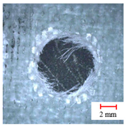 | 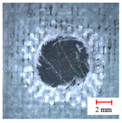 |
| Candle Core Drill | 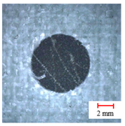 | 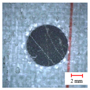 |  |
| Three-Point Step Drill | 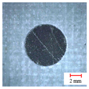 | 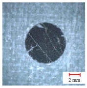 |  |
Publisher’s Note: MDPI stays neutral with regard to jurisdictional claims in published maps and institutional affiliations. |
© 2020 by the authors. Licensee MDPI, Basel, Switzerland. This article is an open access article distributed under the terms and conditions of the Creative Commons Attribution (CC BY) license (http://creativecommons.org/licenses/by/4.0/).
Share and Cite
Wang, F.-J.; Zhao, M.; Yan, J.-B.; Qiu, S.; Liu, X.; Zhang, B.-Y. Investigation of Damage Reduction When Dry-Drilling Aramid Fiber-Reinforced Plastics Based on a Three-Point Step Drill. Materials 2020, 13, 5457. https://doi.org/10.3390/ma13235457
Wang F-J, Zhao M, Yan J-B, Qiu S, Liu X, Zhang B-Y. Investigation of Damage Reduction When Dry-Drilling Aramid Fiber-Reinforced Plastics Based on a Three-Point Step Drill. Materials. 2020; 13(23):5457. https://doi.org/10.3390/ma13235457
Chicago/Turabian StyleWang, Fu-Ji, Meng Zhao, Jian-Bo Yan, Shen Qiu, Xin Liu, and Bo-Yu Zhang. 2020. "Investigation of Damage Reduction When Dry-Drilling Aramid Fiber-Reinforced Plastics Based on a Three-Point Step Drill" Materials 13, no. 23: 5457. https://doi.org/10.3390/ma13235457