Crack Growth Behavior of Additively Manufactured 316L Steel—Influence of Build Orientation and Heat Treatment

 ,
,  , ,
, ,  , , and
Abstract
:1. Introduction
2. Materials and Methods
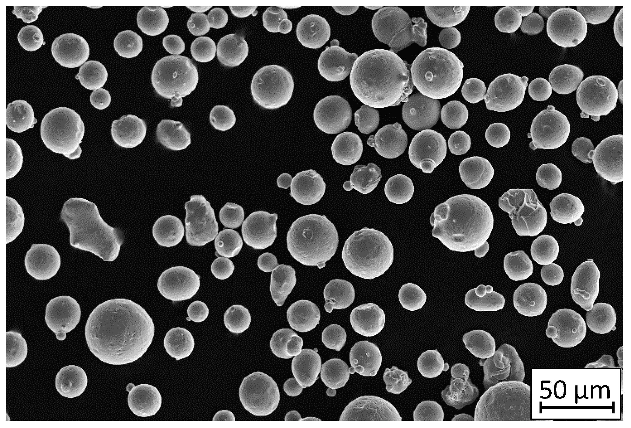
2.1. Material
2.2. Description of the Manufacturing Process
- Laser power: 190 W,
- Exposure velocity: 900 mm/s,
- Hatching distance (distance between exposure lines): 0.12 mm,
- Layer thickness: 0.03 mm
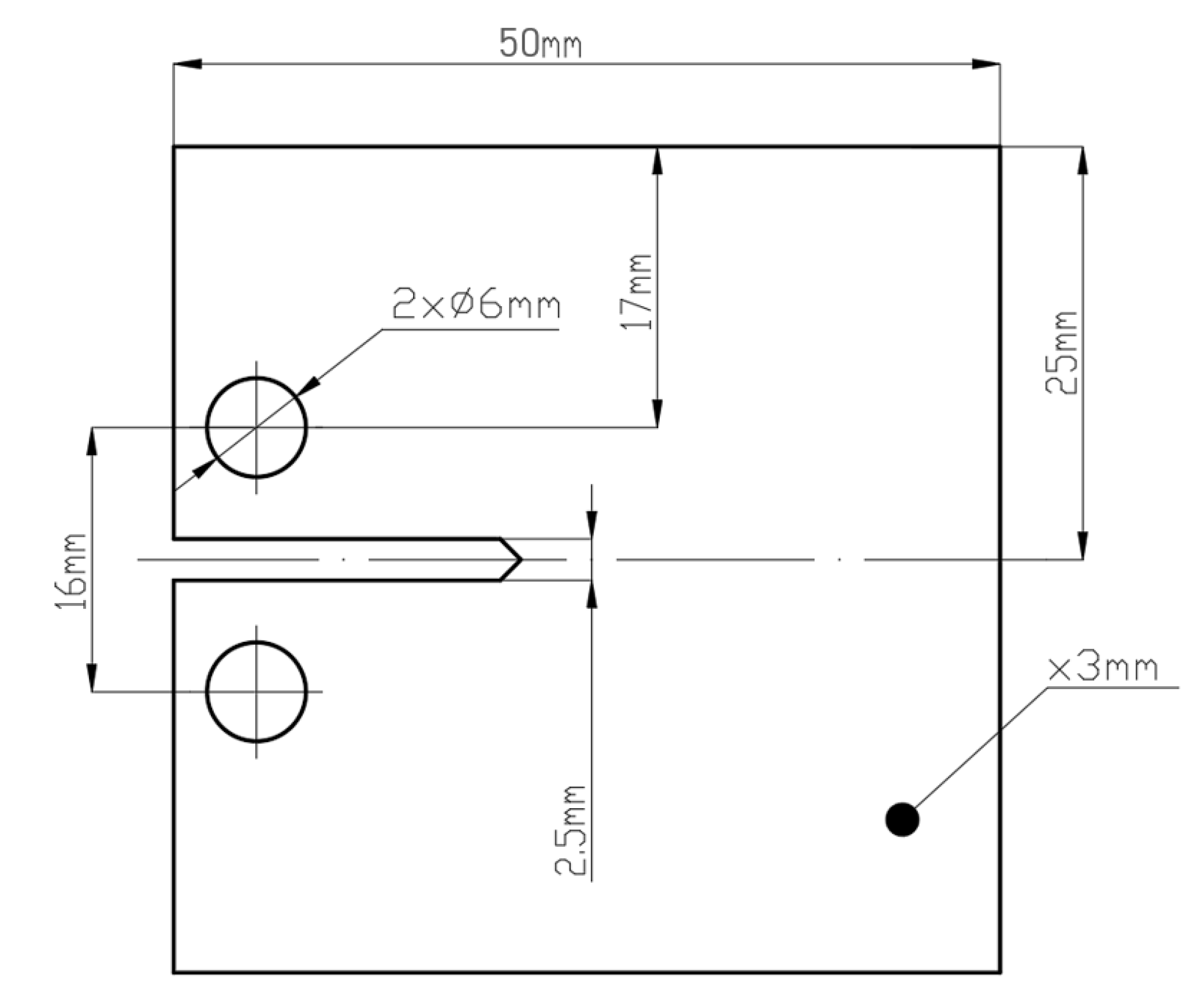
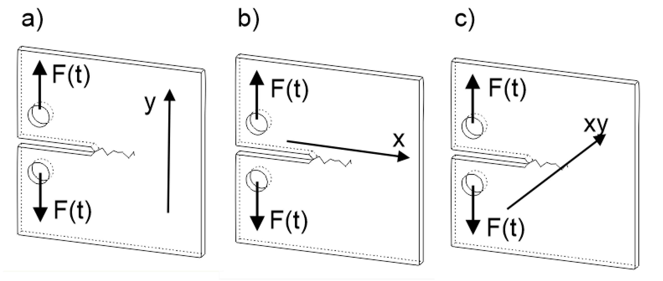
2.3. Description of the Testing Methodology
3. Results and Discussion
3.1. Microstructure Analysis
3.2. Static Tensile Testing Results
3.3. Crack Growth Behavior
4. Conclusions
- (1)
- Microstructural investigation enabled us to expose that after removal of a typical, layered structure of the material after heat treatment of additive manufactured parts a different shaped-grains were obtained. This caused a fatigue life increase but also generated a lot of microcracks which caused a rapid cracking phenomenon. A similar phenomenon was noticed after conventionally made material heat treatment, where the shape and size of elongated grains changed after material rolling and this affected the appearance of microcracks in the material volume during fatigue loading.
- (2)
- Proper orientation of parts in additive manufacturing allows one to achieve a fatigue life and cracking growth behavior similar to that of conventionally made material.
- (3)
- Solution heat treatment of additively manufactured 316L steel increases the fatigue life of produced parts, but completely changes the cracking growth behavior. That kind of material has no significantly visible cracking symptoms. In the material volume, many microcracks appear during cyclic loading which can merge, thus changing the cracking character.
- (4)
- The presence of porosity and non-melted grains introduces a structural heterogeneity that causes a negative, local stress concentration. That phenomenon directly influences the change in characteristic cracking from plastic fatigue cracking with visible fatigue striations to dynamic, brittle-like cracking.
- (5)
- Heat treatment of additively manufactured completely changes the fatigue crack behavior and total fatigue life of the processed part. The influence of solution annealing on AM materials is opposite to that of the same heat treatment of the same material, but manufactured conventionally.
Author Contributions
Funding
Acknowledgments
Conflicts of Interest
References
- Kucewicz, M.; Baranowski, P.; Stankiewicz, M.; Konarzewski, M.; Płatek, P.; Małachowski, J. Modelling and testing of 3D printed cellular structures under quasi-static and dynamic conditions. Thin-Walled Struct. 2019, 145, 106385. [Google Scholar] [CrossRef]
- Sienkiewicz, J.; Płatek, P.; Jiang, F.; Sun, X.; Rusinek, A. Investigations on the Mechanical Response of Gradient Lattice Structures Manufactured via SLM. Metals 2020, 10, 213. [Google Scholar] [CrossRef] [Green Version]
- Kluczyński, J.; Śnieżek, L.; Grzelak, K.; Janiszewski, J.; Płatek, P.; Torzewski, J.; Szachogłuchowicz, I.; Gocman, K. Influence of Selective Laser Melting Technological Parameters on the Mechanical Properties of Additively Manufactured Elements Using 316L Austenitic Steel. Materials 2020, 13, 1449. [Google Scholar] [CrossRef] [PubMed] [Green Version]
- Kluczyński, J.; Sniezek, L.; Grzelak, K.; Torzewski, J. The influence of layer re-melting on tensile and fatigue strength of selective laser melted 316L steel. In Proceedings of the 12th International Conference on Intelligent Technologies in Logistics and Mechatronics Systems, ITELMS 2018, Panevezys, Lithuania, 26–27 April 2018; pp. 115–123. [Google Scholar]
- Zhang, Z.; Chu, B.; Wang, L.; Lu, Z. Comprehensive effects of placement orientation and scanning angle on mechanical properties and behavior of 316L stainless steel based on the selective laser melting process. J. Alloys Compd. 2019, 791, 166–175. [Google Scholar] [CrossRef]
- Guzanová, A.; Brezinová, J.; Draganovská, D.; Maruschak, P.O. Properties of coatings created by HVOF technology using micro-and nano-sized powder. Koroze Ochr. Mater. 2019, 63, 86–93. [Google Scholar] [CrossRef] [Green Version]
- Hutsaylyuk, V.; Student, M.; Dovhunyk, V.; Posuvailo, V.; Student, O.; Maruschak, P.; Koval’chuck, I. Effect of hydrogen on the wear resistance of steels upon contact with plasma electrolytic oxidation layers synthesized on aluminum alloys. Metals 2019, 9, 280. [Google Scholar] [CrossRef] [Green Version]
- Spierings, A.B.; Starr, T.L.; Wegener, K. Fatigue performance of additive manufactured metallic parts. Rapid Prototyp. J. 2013, 19, 88–94. [Google Scholar] [CrossRef]
- Pace, M.L.; Guarnaccio, A.; Dolce, P.; Mollica, D.; Parisi, G.P.; Lettino, A.; Medici, L.; Summa, V.; Ciancio, R.; Santagata, A. 3D additive manufactured 316L components microstructural features and changes induced by working life cycles. Appl. Surf. Sci. 2017, 418, 437–445. [Google Scholar] [CrossRef]
- Kalentics, N.; Boillat, E.; Peyre, P.; Ćirić-Kostić, S.; Bogojević, N.; Logé, R.E. Tailoring residual stress profile of Selective Laser Melted parts by Laser Shock Peening. Addit. Manuf. 2017, 16, 90–97. [Google Scholar] [CrossRef] [Green Version]
- Suryawanshi, J.; Prashanth, K.G.; Ramamurty, U. Mechanical behavior of selective laser melted 316L stainless steel. Mater. Sci. Eng. A 2017, 696, 113–121. [Google Scholar] [CrossRef]
- Rokicki, P.; Kozik, B.; Budzik, G.; Dziubek, T.; Bernaczek, J.; Przeszlowski, L.; Markowska, O.; Sobolewski, B.; Rzucidlo, A. Manufacturing of aircraft engine transmission gear with SLS (DMLS) method. Aircr. Eng. Aerosp. Technol. 2016, 88, 397–403. [Google Scholar] [CrossRef]
- Rokicki, P.; Budzik, G.; Kubiak, K.; Dziubek, T.; Zaborniak, M.; Kozik, B.; Bernaczek, J.; Przeszlowski, L.; Nowotnik, A. The assessment of geometric accuracy of aircraft engine blades with the use of an optical coordinate scanner. Aircr. Eng. Aerosp. Technol. 2016, 88, 374–381. [Google Scholar] [CrossRef]
- Du Plessis, A.; Broeckhoven, C.; Yadroitsava, I.; Yadroitsev, I.; Hands, C.H.; Kunju, R.; Bhate, D. Beautiful and Functional: A Review of Biomimetic Design in Additive Manufacturing. Addit. Manuf. 2019, 27, 408–427. [Google Scholar] [CrossRef]
- Li, C.; Liu, Z.Y.; Fang, X.Y.; Guo, Y.B. Residual Stress in Metal Additive Manufacturing. Procedia Cirp 2018, 71, 348–353. [Google Scholar] [CrossRef]
- Fergani, O.; Bratli Wold, A.; Berto, F.; Brotan, V.; Bambach, M. Study of the effect of heat treatment on fatigue crack growth behaviour of 316L stainless steel produced by selective laser melting. Fatigue Fract. Eng. Mater. Struct. 2018, 41, 1102–1119. [Google Scholar] [CrossRef]
- Saeidi, K.; Gao, X.; Zhong, Y.; Shen, Z.J. Hardened austenite steel with columnar sub-grain structure formed by laser melting. Mater. Sci. Eng. A 2015, 625, 221–229. [Google Scholar] [CrossRef]
- Riemer, A.; Leuders, S.; Thöne, M.; Richard, H.A.; Tröster, T.; Niendorf, T. On the fatigue crack growth behavior in 316L stainless steel manufactured by selective laser melting. Eng. Fract. Mech. 2014, 120, 15–25. [Google Scholar] [CrossRef]
- Xu, K.; Li, B.; Li, S.; Luo, M.; Gao, X.; Jiang, C.; Song, L. In situ observation for the fatigue crack growth mechanism of 316L stainless steel fabricated by laser engineered net shaping. Int. J. Fatigue 2020, 130, 105272. [Google Scholar] [CrossRef]
- Brenne, F.; Niendorf, T. Damage tolerant design by microstructural gradation—Influence of processing parameters and build orientation on crack growth within additively processed 316L. Mater. Sci. Eng. A 2019, 764, 138186. [Google Scholar] [CrossRef]
- Suryawanshi, J.; Prashanth, K.G.; Ramamurty, U. Tensile, fracture, and fatigue crack growth properties of a 3D printed maraging steel through selective laser melting. J. Alloys Compd. 2017, 725, 355–364. [Google Scholar] [CrossRef]
- Riemer, A.; Richard, H.A.; Brüggemann, J.P.; Wesendahl, J.N. Fatigue crack growth in additive manufactured products. Frat. Integrita Strutt. 2015, 9, 437–446. [Google Scholar]
- Lo, K.H.; Shek, C.H.; Lai, J.K.L. Recent developments in stainless steels. Mater. Sci. Eng. R Rep. 2009, 65, 39–104. [Google Scholar] [CrossRef]
- Vach, M.; Kuníková, T.; Dománková, M.; Ševc, P.; Čaplovič, Ľ.; Gogola, P.; Janovec, J. Evolution of secondary phases in austenitic stainless steels during long-term exposures at 600, 650 and 800 °C. Mater. Charact. 2008, 59, 1792–1798. [Google Scholar] [CrossRef]


| C | Mn | Si | P | S | N | Cr | Mo | Ni |
|---|---|---|---|---|---|---|---|---|
| max. 0.03 | max. 2.00 | max. 0.75 | max. 0.04 | max. 0.03 | max. 0.10 | 16.00–18.00 | 2.00–3.00 | 10.00–14.00 |
| Condition | Microstructure |
|---|---|
| Selective laser melted (SLM) |  |
| Selective laser melted and solution annealed (SLM_S) |  |
| Conventionally manufactured (CM) |  |
| Conventionally manufactured and solution annealed (CM_S) | 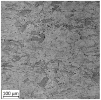 |
| Condition | 0.2% YS (MPa) | UTS (MPa) | εf (%) | E (GPa) |
|---|---|---|---|---|
| Selective laser melted (SLM) | 554 | 666 | 44.91 | 169.9 |
| Selective laser melted and solution annealed (SLM_S) | 371 | 632 | 47.35 | 170.6 |
| Conventionally manufactured (CM) | 346 | 564 | 64.11 | 204.5 |
| Conventionally manufactured and solution annealed (CM_S) | 215 | 567 | 69.95 | 205.3 |
| Crack Growth Curves | Fracture Surfaces | ||
|---|---|---|---|
Horizontal direction of layers deposition/sheet rolling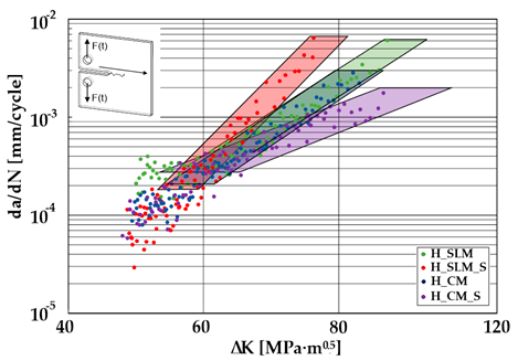 | Material type | H_SLM |  |
| H_SLM_S |  | ||
| H_CM | 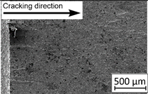 | ||
| H_CM _S | 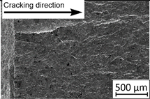 | ||
Vertical direction of layers deposition/sheet rolling | Material type | V_SLM | 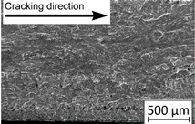 |
| V_SLM_S | 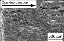 | ||
| V_CM | 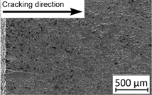 | ||
| V_CM _S | 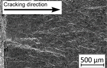 | ||
45°-angled direction of layers deposition/sheet rolling | Material type | A_SLM | 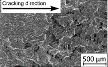 |
| A_SLM_S | 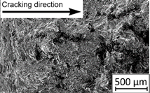 | ||
| A_CM | 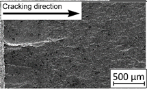 | ||
| A_CM _S | 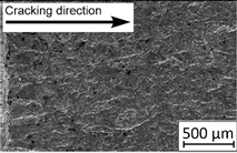 |
| Condition | Coefficient Type | Horizontally Oriented | Vertically Oriented | 45° Angled |
|---|---|---|---|---|
| Selective laser melted (SLM) | C-coefficient | 7 × 10⁻¹⁵ | 2 × 10⁻¹⁴ | 5 × 10⁻¹⁵ |
| m-coefficient | 6.00 | 5.86 | 6.06 | |
| Selective laser melted processed and solution annealed (SLM_S) | C-coefficient | 3 × 10⁻²⁰ | 10−18 | 5 × 10⁻²⁸ |
| m-coefficient | 9.16 | 8.27 | 13.14 | |
| Conventionally manufactured (CM) | C-coefficient | 5 × 10⁻¹⁵ | 5 × 10⁻¹¹ | 6 × 10⁻¹² |
| m-coefficient | 6.08 | 3.72 | 4 × 24 | |
| Conventionally manufactured and solution annealed (CM_S) | C-coefficient | 8 × 10⁻¹¹ | 2 × 10⁻¹¹ | 5 × 10⁻¹⁰ |
| m-coefficient | 3.74 | 4.09 | 3.30 |
© 2020 by the authors. Licensee MDPI, Basel, Switzerland. This article is an open access article distributed under the terms and conditions of the Creative Commons Attribution (CC BY) license (http://creativecommons.org/licenses/by/4.0/).
Share and Cite
Kluczyński, J.; Śnieżek, L.; Grzelak, K.; Torzewski, J.; Szachogłuchowicz, I.; Wachowski, M.; Łuszczek, J. Crack Growth Behavior of Additively Manufactured 316L Steel—Influence of Build Orientation and Heat Treatment. Materials 2020, 13, 3259. https://doi.org/10.3390/ma13153259
Kluczyński J, Śnieżek L, Grzelak K, Torzewski J, Szachogłuchowicz I, Wachowski M, Łuszczek J. Crack Growth Behavior of Additively Manufactured 316L Steel—Influence of Build Orientation and Heat Treatment. Materials. 2020; 13(15):3259. https://doi.org/10.3390/ma13153259
Chicago/Turabian StyleKluczyński, Janusz, Lucjan Śnieżek, Krzysztof Grzelak, Janusz Torzewski, Ireneusz Szachogłuchowicz, Marcin Wachowski, and Jakub Łuszczek. 2020. "Crack Growth Behavior of Additively Manufactured 316L Steel—Influence of Build Orientation and Heat Treatment" Materials 13, no. 15: 3259. https://doi.org/10.3390/ma13153259