Enhancement of the Quality of the Shell-Core Bond Interface in Duplex Work Rolls Manufactured by Centrifugal Casting Used in Hot Strip Mills


Abstract
:1. Introduction
2. Materials and Methods
- Impact toughness using a Charpy pendulum.
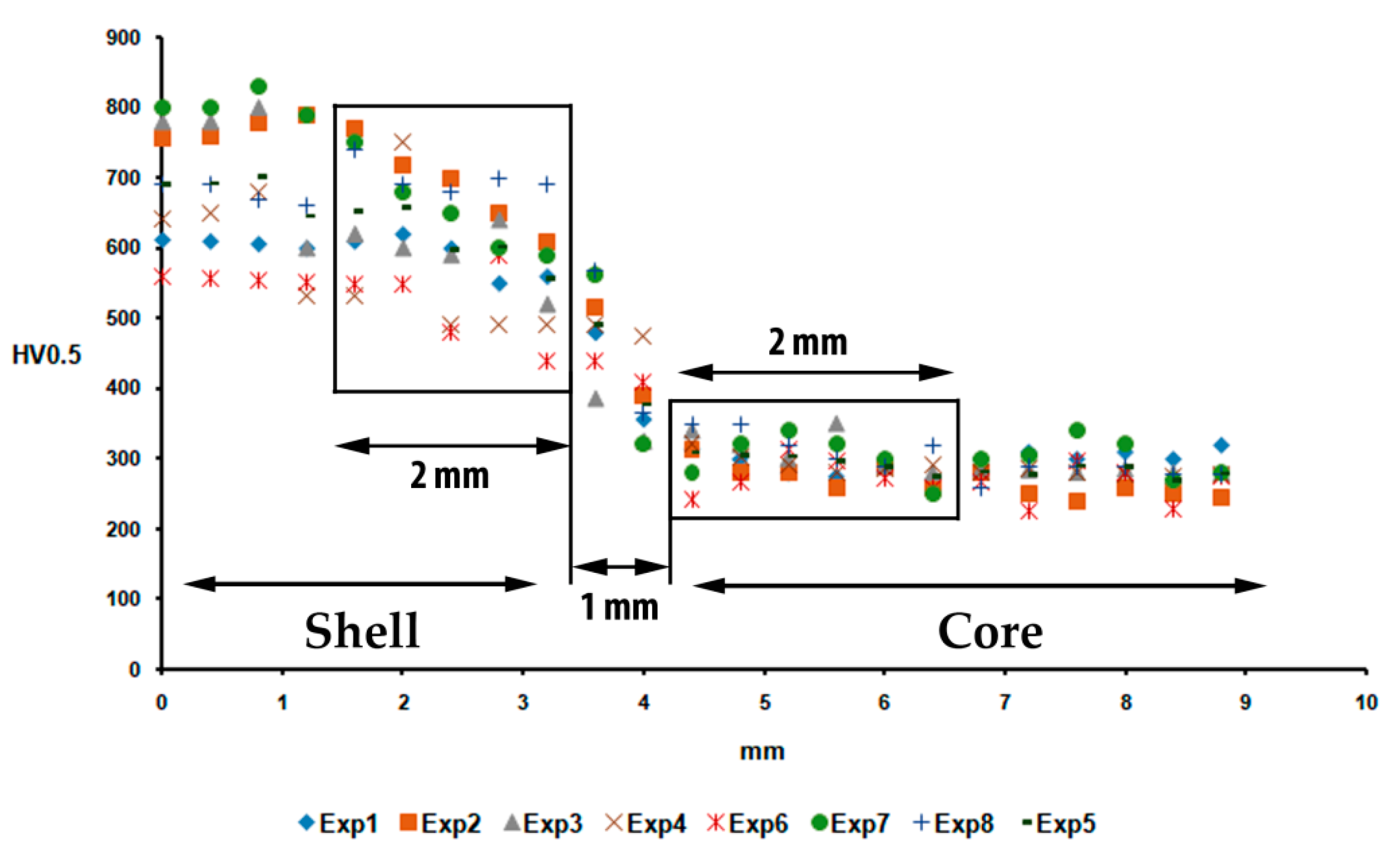
- Hardness of the part of the shell adjacent to the bond edge. To obtain this value, the hardness data obtained at a thickness of 2 mm from this edge were considered.
- Hardness of the part of the core adjacent to the bond edge. Likewise, the hardness data obtained at a thickness of 2 mm from this edge were considered to obtain this value.
3. Results
4. Conclusions
- Inoculate the shell (working layer) with 0.6 kg/T SiCaMn, as this promotes discontinuity in the carbide network and leads to an increase in the impact toughness of the bond interface.
- Avoid inoculation with FeSi-La, as this inoculant promotes an increase in the number of graphite nodules per unit area and a lamellar morphology of this graphite, reducing the impact toughness in this bond interface.
- Furthermore, the addition of Mg at values around 0.04 wt.% has been found to produce an increase in hardness in the shell region adjacent to the bond interface. This is due to two simultaneous phenomena:
- The tendency of Mg to accumulate in the innermost region of the shell during centrifugal casting as a result of its low density.
- Its tendency to favor the precipitation of white eutectic versus grey eutectic when the Si content is low.
Author Contributions
Funding
Conflicts of Interest
References
- Strilkova, L.; Valek, T.; Tanger, L.T.D. Microstructural investigation of icdp iron designed for working layers of composite centrifugally cast rolls in hot rolling mills. In Proceedings of the 21st International on Conference Metallurgy and Materials, Brno, Czech Republic, 23–25 May 2012; pp. 788–794. [Google Scholar]
- Sergio, V.; Ishikawa, S.; Yamamoto, K.; Miyahara, H.; Ogi, K.; Kamimiyada, K. Control of graphite formation in solidification of white cast iron. Int. J. Cast Met. Res. 2008, 21, 27–30. [Google Scholar] [CrossRef]
- Gowda, D.; Kumar, D.C.; Sandeep, G.M.; Parthasarathy, A.; Chandrashekar, S. Tribological characterization of centrifugally cast graphite cast iron under dry and wet conditions. Mater. Today Proc. 2018, 5, 145–151. [Google Scholar] [CrossRef]
- Belzunce, F.J.; Ziadi, A.; Rodriguez, C. Structural integrity of hot strip mill rolling rolls. Eng. Fail. Anal. 2004, 11, 789–797. [Google Scholar] [CrossRef]
- Guerrero, M.P.; Pérez, A.; Colás, R. Heat Transfer to Work Rolls during Hot Rolling Steel; International Convention Centre Birmingham: Birmingham, UK, 1996; pp. 108–112. [Google Scholar]
- Wan, J.; Qing, J.J.; Xu, M.Z. Designing a novel graphitic white iron for metal-to-metal wear systems. Metall. Mater. Trans. A-Phys. Metall. Mater. Sci. 2019, 50A, 1162–1174. [Google Scholar] [CrossRef]
- Holmgren, D.; Svensson, I.L. Thermal conductivity—structure relationships in grey cast iron. Int. J. Cast Met. Res. 2005, 18, 321–330. [Google Scholar] [CrossRef]
- Elmabrouk, O.; Erfan, O.M.; Kalkanli, A. The effect of magnisium to sulfur ratio on the graphite morphology of graphite cast iron produced at differrent section thicknesses. Manuf. Sci. Technol. 2012, 383–390, 5880–5885. [Google Scholar]
- Wang, G.Q.; Chen, X.; Li, Y.X.; Liu, Z.L. Effects of inoculation on the pearlitic gray cast iron with high thermal conductivity and tensile strength. Materials 2018, 11, 1876. [Google Scholar] [CrossRef]
- Ding, X.F.; Huang, H.; Matthias, W.; Huang, S.Y.; Lu, Y.H.; Feng, Q. Development of high performance cast iron with combination of improved mechanical and thermal properties through mo addition. Metall. Mater. Trans. A-Phys. Metall. Mater. Sci. 2018, 49A, 3173–3177. [Google Scholar] [CrossRef]
- Lekakh, S.N.; Qing, J.; Richards, V.L.; Amer Foundry, S. Investigation of cast iron processing to produce controlled dual graphite structure in castings. Trans. Am. Foundry Soc. 2012, 120, 297–306. [Google Scholar]
- Pero-Sanz, J.A. Fundiciones Férreas. Dossat: Madrid, Spain, 1994; p. 154. [Google Scholar]
- Xin, Z.; Perks, M.C. Centrifugal Casting Hss Roll for Narrow Strip Rod Mills. In Proceedings of the 42nd Mechanical Working and Steel Processing Conference, Toronto, ON, Canada, 22–25 October 2000; Iron and Steel Society: Toronto, ON, Canada, 2000; pp. 183–191. [Google Scholar]
- Bedolla-Jacuinde, A. Microstructure of vanadium-, niobium-and titanium-alloyed high-chromium white cast irons. Int. J. Cast Met. Res. 2001, 13, 343–361. [Google Scholar] [CrossRef]
- Mourad, M.M.; El-Hadad, S.; Ibrahim, M.M. Effects of molybdenum addition on the microstructure and mechanical properties of ni-hard white cast iron. Trans. Indian Inst. Met. 2015, 68, 715–722. [Google Scholar] [CrossRef]
- Antolin, J.F.A.; Perez, C.H.A.; Lozano, J.A. Identification of metallurgical manufacturing factors with a significant effect on the flexural strength of mottled ni-hard cast irons through a design of experiments approach. Int. J. Met. 2017, 11, 467–474. [Google Scholar]
- Gowda, H.S.D.; Mukunda, P.G.; Herbert, M.A. Correlation of tribological properties with microstructure and mechanical properties of graphite cast irons centrifugally cast for engine liner. Trans. Indian Inst. Met. 2014, 67, 731–740. [Google Scholar] [CrossRef]
- Qihong, C.; Zhan-Wen, W.; Yi, J.; Yehua, J.; Fei, L.; Hanguang, F. A study of centrifugal cast high boron high speed steel. Mater. Werkst. 2014, 45, 582–590. [Google Scholar] [CrossRef]
- Yamamoto, M.; Narita, I.; Miyahara, H. Fractal analysis of solidification microstructure of high carbon high alloy cast roll manufactured by centrifugal casting. Tetsu Hagane J. Iron Steel Inst. Jpn. 2013, 99, 72–79. [Google Scholar] [CrossRef]
- Bai, Y.L.; Luan, Y.K.; Song, N.N.; Kang, X.H.; Li, D.Z.; Li, Y.Y. Chemical compositions, microstructure and mechanical properties of roll core used ductile iron in centrifugal casting composite rolls. J. Mater. Sci. Technol. 2012, 28, 853–858. [Google Scholar] [CrossRef]
- Fu, H.G.; Xiao, Q.; Xing, H.D. A study of segregation mechanism in centrifugal cast high speed steel rolls. Mater. Sci. Eng. A Struct. Mater. Prop. Microstruct. Process. 2008, 479, 253–260. [Google Scholar] [CrossRef]
- Mitrovic, D.; Mrvar, P.; Petric, M. Characterization of cast-iron gradient castings. Mater. Tehnol. 2015, 49, 871–875. [Google Scholar] [CrossRef]
- Fernandez-Pariente, I.; Ziadi, A.; Belzunce, F.J. Study of the high strenght steel-nodular iron interphase developed in bimetallic rolls produced by centrifugal casting. Bol. Soc. Esp. Ceram. Y Vidr. 2004, 43, 263–266. [Google Scholar]
- Schon, C.G.; Sinatora, A. Hot rolling mill roll microstructure interpretation: A computational thermodynamics study. J. Phase Equilibria 2001, 22, 470–474. [Google Scholar] [CrossRef]
- Sinha, P.; Indimath, S.S.; Mukhopadhyay, G.; Bhattacharyya, S. Failure of a work roll of a thin strip rolling mill: A case study. Struct. Integr. 2014, 86, 940–948. [Google Scholar] [CrossRef]
- Ozdemir, Z. Effect of heat treatment on the impact toughness of ‘high-chromium cast iron—Low alloy steel’ bimetal components. Met. Sci. Heat Treat. 2017, 58, 738–741. [Google Scholar] [CrossRef]
- Yazdani, M.; Toroghinejad, M.R.; Hashemi, S.M. Effects of heat treatment on interface microstructure and mechanical properties of explosively welded ck60/st37 plates. J. Mater. Eng. Perform. 2016, 25, 5330–5342. [Google Scholar] [CrossRef]
- Imran, M.K.; Masood, S.H.; Brandt, M.; Bhattacharya, S.; Mazumder, J. Direct metal deposition (dmd) of h13 tool steel on copper alloy substrate: Evaluation of mechanical properties. Mater. Sci. Eng. A Struct. Mater. Prop. Microstruct. Process. 2011, 528, 3342–3349. [Google Scholar] [CrossRef]
- Cofino-Villar, A.; Alvarez-Antolin, J.F.; Asensio-Lozano, J. Enhanced fracture strength in the working layer of rolls manufactured in ni-hard cast iron alloyed with mo, nb and mg. Metals 2018, 8, 725. [Google Scholar] [CrossRef]
- Cofino-Villar, A.; Alvarez-Antolin, F.; Asensio-Lozano, J.; Garcia-Garcia, M. Control over the percentage, shape and size of the graphite particles in martensitic white castings alloyed with cr, nb and mg. Materials 2019, 12, 185. [Google Scholar] [CrossRef]
- Prat-Bartés, A.; Tort-Martorell, X.; Grima-Cintas, P.; Pozueta-Fernández, L.; Solé-Vidal, I. Métodos Estadísticos, 2nd ed.; Barcelona: Barcelona, Spain, 2004; p. 376. [Google Scholar]
- Dun, X.L.; Liu, K.P.; Liu, H.S.; Lai, J.P.; Fu, X.H.; Zhou, J. Effect of multicomponent modifier on microstructure and mechanical properties of high ni-cr-mo cast iron. Mater. Sci. Technol. 2011, 27, 1840–1845. [Google Scholar] [CrossRef]
- Asensio-Lozano, J.; Alvarez-Antolin, J.F.; Voort, G.F.V. Identification and quantification of active manufacturing factors for graphite formation in centrifugally cast nihard cast irons. J. Mater. Process. Tech. 2008, 206, 202–215. [Google Scholar] [CrossRef]
- Asensio-Lozano, J.; Alvarez-Antolin, J.F. Saturated fractional design of experiments: Toughness and graphite phase optimizing in nihard cast irons. J. Mater. Eng. and Perform. 2008, 17, 216–223. [Google Scholar] [CrossRef]


| Part of the Roll | C | Si | Mn | Ni | Cr | Nb | Mo | Mg |
|---|---|---|---|---|---|---|---|---|
| Shell | 3.2–3.4 | 0.9–1.0 | 0.8–1.0 | 4.4–4.6 | 1.7–1.8 | 0.65–0.75 | 0.25 | - |
| Core | 3–3.02 | 2.2–2.3 | 0.2–0.4 | 0.1–0.2 | 0–0.1 | - | 0–0.02 | 0.06–0.08 |
| Factors | Levels | |||
|---|---|---|---|---|
| Code | Description | Units | −1 Level | +1 Level |
| A | FeSi-La | wt.% | 0 | 0.27 |
| B | FeB | wt.% | 0.3 | 0.6 |
| C | Liquidus Temperature | K | 1523–1528 | 1543–1548 |
| D | Si | wt.% | 0.8–0.85 | 1.1–1.15 |
| E | SiCaMn | wt.% | 0.03 | 0.06 |
| F | Mg | wt.% | 0 | 0.04 |
| No. | A | B | C | D | E | F | Confounding Pattern |
|---|---|---|---|---|---|---|---|
| 1 | −1 | −1 | −1 | +1 | +1 | +1 | Mean |
| 2 | +1 | −1 | −1 | −1 | −1 | +1 | A/BD/CE |
| 3 | −1 | +1 | −1 | −1 | +1 | −1 | B/AD/CF |
| 4 | +1 | +1 | −1 | +1 | −1 | −1 | C/AE/BF |
| 5 | −1 | −1 | +1 | +1 | −1 | −1 | D/AB/EF |
| 6 | +1 | −1 | +1 | −1 | +1 | −1 | E/AC/DF |
| 7 | −1 | +1 | +1 | −1 | −1 | +1 | F/BC/DE |
| 8 | +1 | +1 | +1 | +1 | +1 | +1 | AF/BE/CD |
| Inoculants | Si | Ca | Al | Mn | Ti | Ba | C | Bi | S | P | B | La | Mg |
|---|---|---|---|---|---|---|---|---|---|---|---|---|---|
| FeSi-La | 66.0 | 2.5 | 0.8 | - | - | 0.3 | - | 0.3 | - | - | - | 0.8 | |
| FeSiMg | 28.7 | - | - | - | - | - | - | - | - | - | - | - | 15.0 |
| SiCaMn | 58.3 | 16.4 | 1.1 | 14.8 | 0.03 | 0.6 | 0.03 | 0.03 | - | ||||
| FeB | 0.4 | - | - | - | - | 0.3 | - | - | 17.9 |
| Casting Parameters | Units | Experiment Number | |||||||
|---|---|---|---|---|---|---|---|---|---|
| 1 | 2 | 3 | 4 | 5 | 6 | 7 | 8 | ||
| C | % | 3.35 | 3.46 | 3.4 | 3.28 | 2.94 | 3.04 | 3.02 | 3.04 |
| Si | % | 1.13 | 0.88 | 0.87 | 1.18 | 1.16 | 0.89 | 0.87 | 1.15 |
| Mn | % | 0.77 | 0.78 | 0.79 | 0.77 | 0.79 | 0.83 | 0.80 | 0.82 |
| Ni | % | 4.44 | 4.33 | 4.32 | 4.38 | 4.59 | 4.16 | 4.62 | 4.65 |
| Cr | % | 1.68 | 1.68 | 1.71 | 1.64 | 1.65 | 1.71 | 1.68 | 1.71 |
| Mo | % | 0.26 | 0.25 | 0.25 | 0.24 | 0.25 | 0.25 | 0.26 | 0.26 |
| Mg | % | 0.005 | 0.004 | - | - | - | - | 0.004 | 0.005 |
| B | % | 0.032 | 0.033 | 0.071 | 0.075 | 0.038 | 0.041 | 0.070 | 0.071 |
| Nb | % | 0.64 | 0.72 | 0.68 | 0.61 | 0.74 | 0.75 | 0.73 | 0.61 |
| Liquidus Temperature | K | 1525 | 1527 | 1526 | 1523 | 1546 | 1545 | 1545 | 1543 |
| Experiment | Charpy Test | Hardness of the Shell | Hardness of the Core | Confounding Pattern | |||
|---|---|---|---|---|---|---|---|
| J/cm2 | Effect | HV0.5 | Effect | HV0.5 | Values | ||
| 1 | 3.45 | 3.18 | 590 | 619.37 | 290 | 296.75 | Mean |
| 2 | 2.69 | −0.36 | 707 | −1.75 | 281 | −7.50 | A + BD + CE |
| 3 | 3.66 | 0.13 | 595 | 17.25 | 313 | 22.00 | B + AD + CF |
| 4 | 2.57 | 0.18 | 547 | 19.25 | 294 | 4.50 | C + AE + BF |
| 5 | 3.26 | 0.11 | 619 | −14.25 | 297 | 8.00 | D + AB + EF |
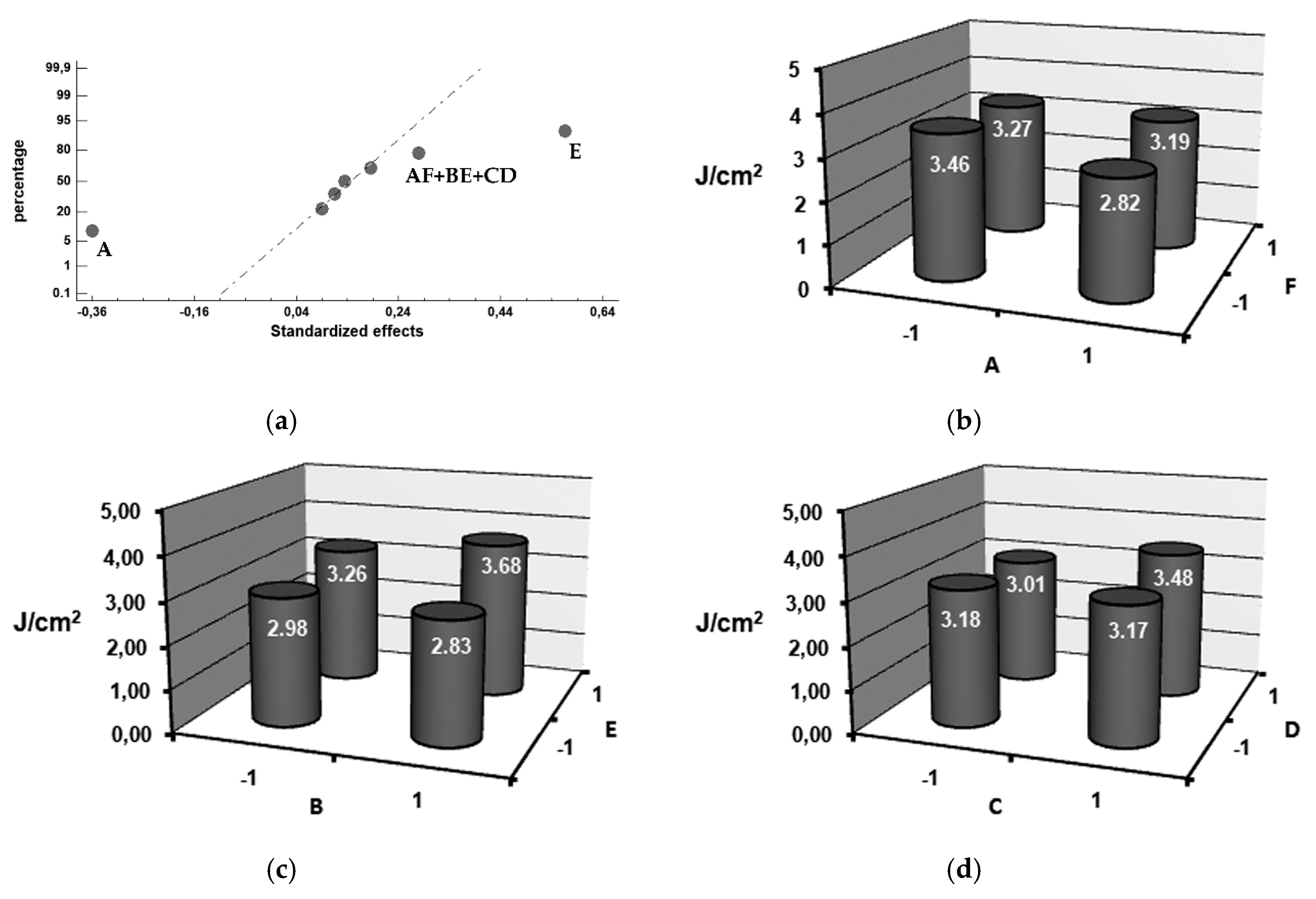
| 6 | 3.07 | 0.56 | 527 | −36.25 | 275 | 6.50 | E + AC + DF |
| 7 | 3.09 | 0.09 | 677 | 94.75 | 302 | 4.00 | F + BC + DE |
| 8 | 3.69 | 0.28 | 693 | 68.25 | 322 | 13.00 | AF + BE + CD |
© 2019 by the authors. Licensee MDPI, Basel, Switzerland. This article is an open access article distributed under the terms and conditions of the Creative Commons Attribution (CC BY) license (http://creativecommons.org/licenses/by/4.0/).
Share and Cite
Cofiño-Villar, A.; Alvarez-Antolin, F.; Asensio-Lozano, J. Enhancement of the Quality of the Shell-Core Bond Interface in Duplex Work Rolls Manufactured by Centrifugal Casting Used in Hot Strip Mills. Materials 2019, 12, 1304. https://doi.org/10.3390/ma12081304
Cofiño-Villar A, Alvarez-Antolin F, Asensio-Lozano J. Enhancement of the Quality of the Shell-Core Bond Interface in Duplex Work Rolls Manufactured by Centrifugal Casting Used in Hot Strip Mills. Materials. 2019; 12(8):1304. https://doi.org/10.3390/ma12081304
Chicago/Turabian StyleCofiño-Villar, Alberto, Florentino Alvarez-Antolin, and Juan Asensio-Lozano. 2019. "Enhancement of the Quality of the Shell-Core Bond Interface in Duplex Work Rolls Manufactured by Centrifugal Casting Used in Hot Strip Mills" Materials 12, no. 8: 1304. https://doi.org/10.3390/ma12081304