Analysis of the Influence of Blanking Clearance on the Wear of the Punch, the Change of the Burr Size and the Geometry of the Hook Blanked in the Hardened Steel Sheet


Abstract
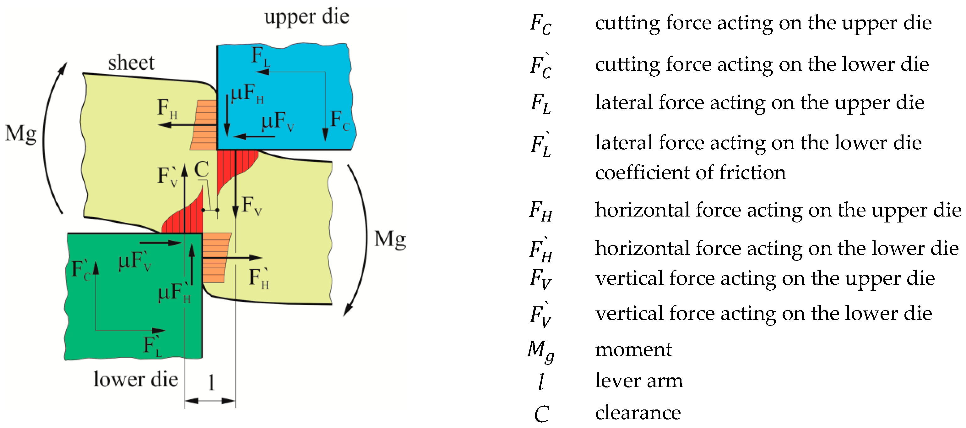
:1. Introduction
2. Materials and Methods
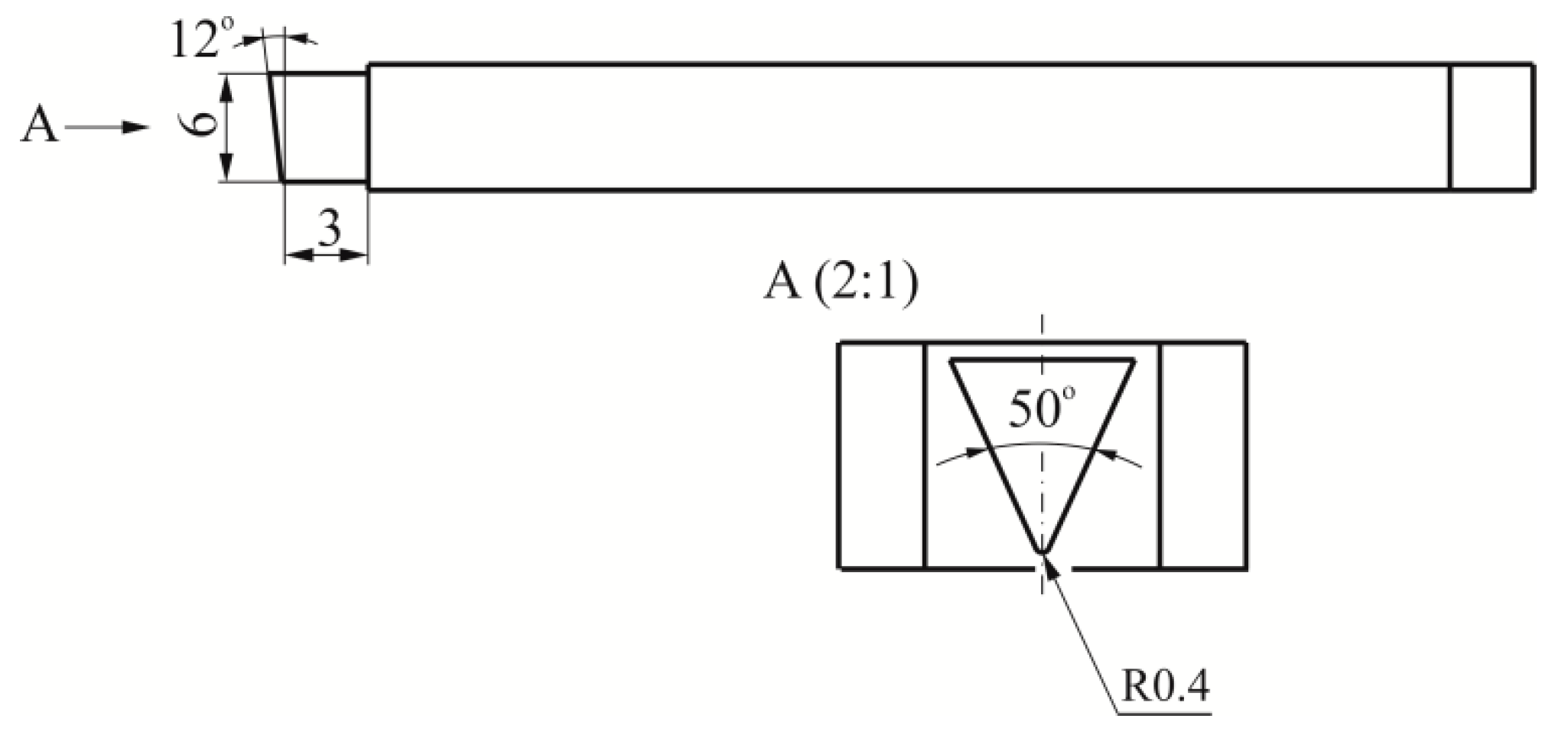
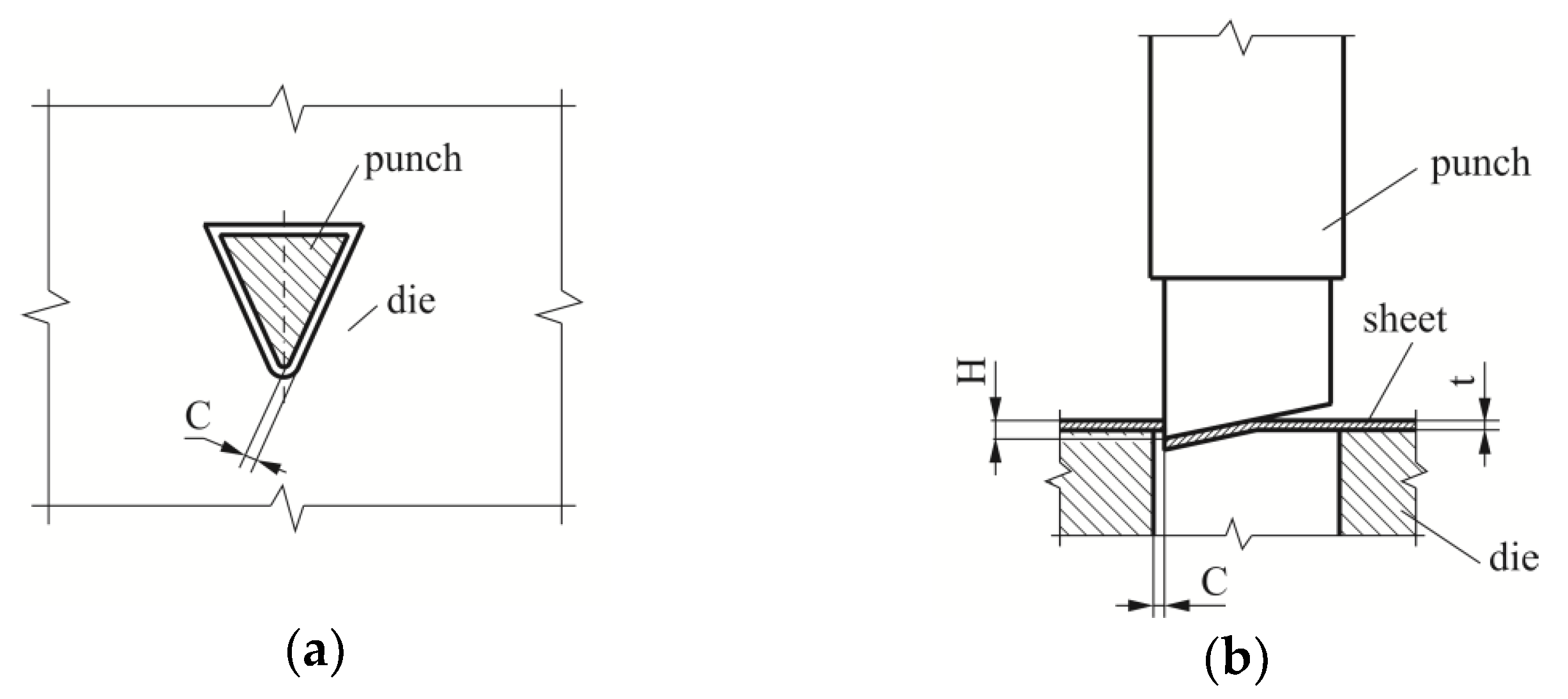
2.1. The Blanking Experiment
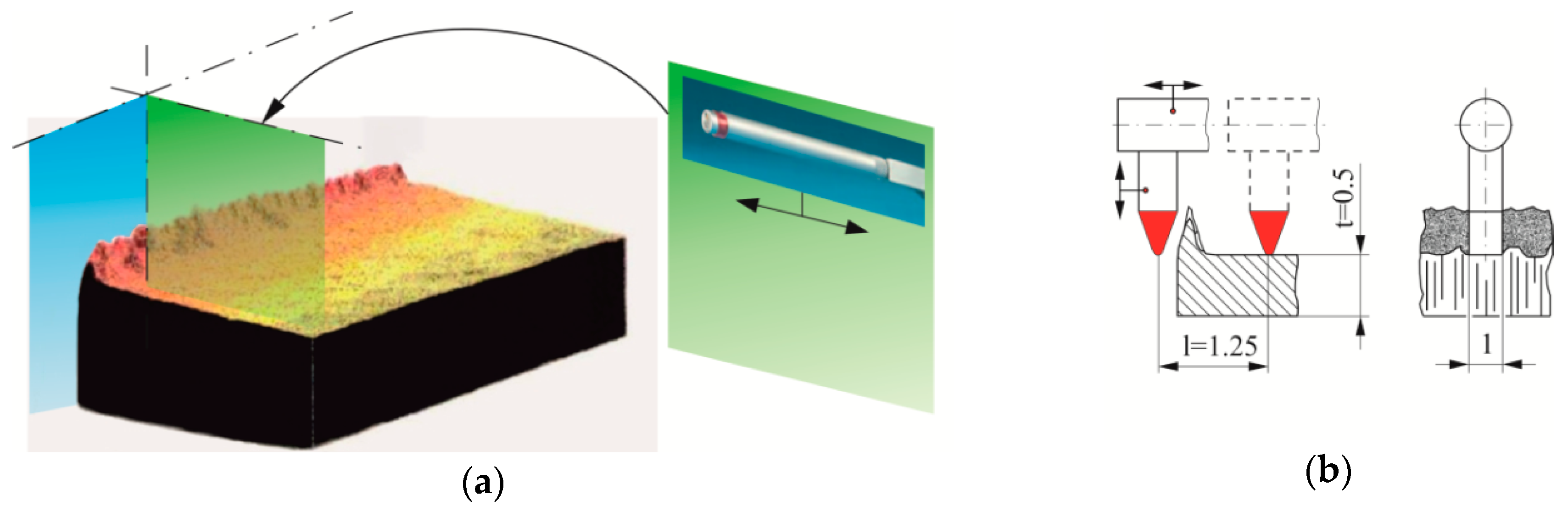
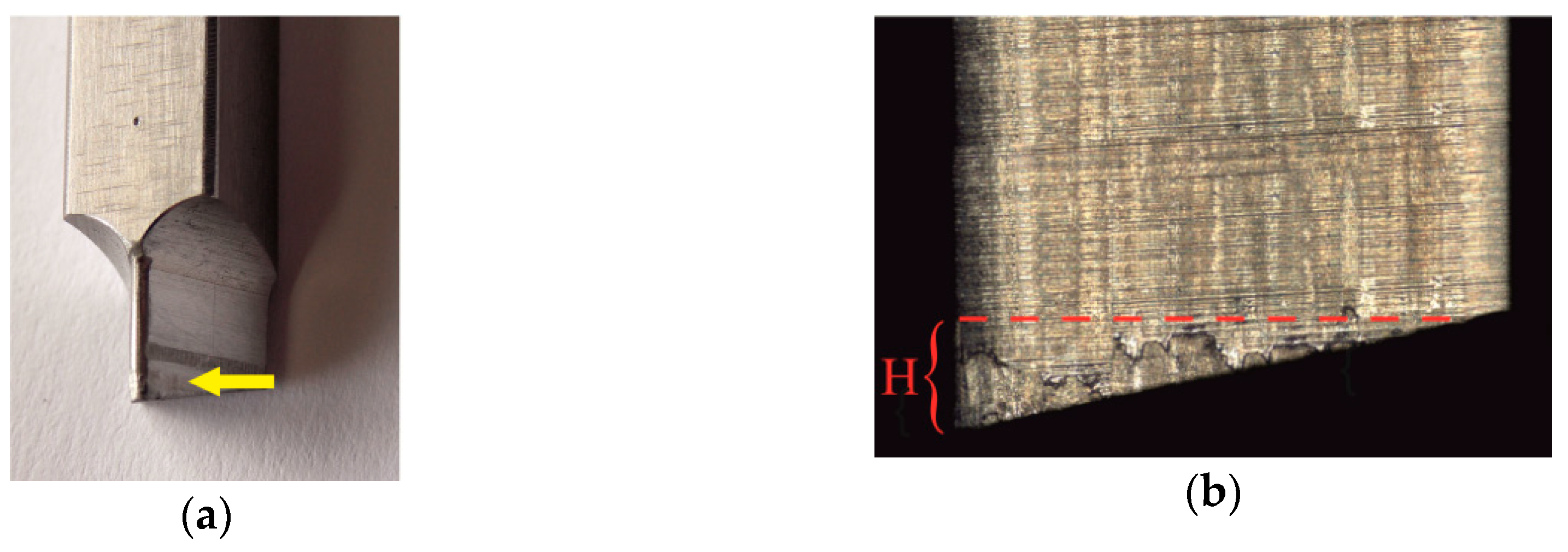
2.2. Measurement of the Hook Profile and the Size of the Burr
3. Results and Discussion
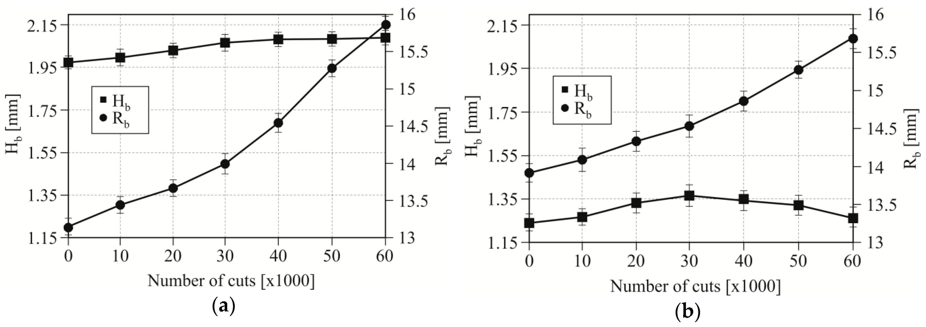
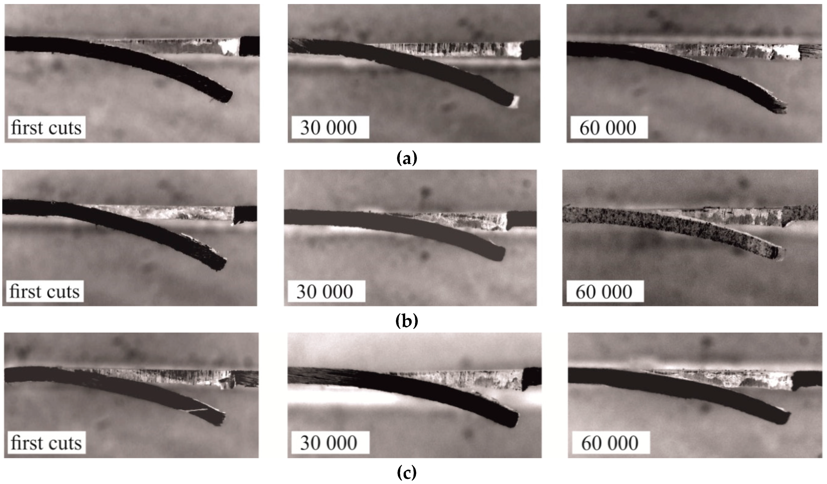
3.1. Bend of the Hook
3.2. Burr Height
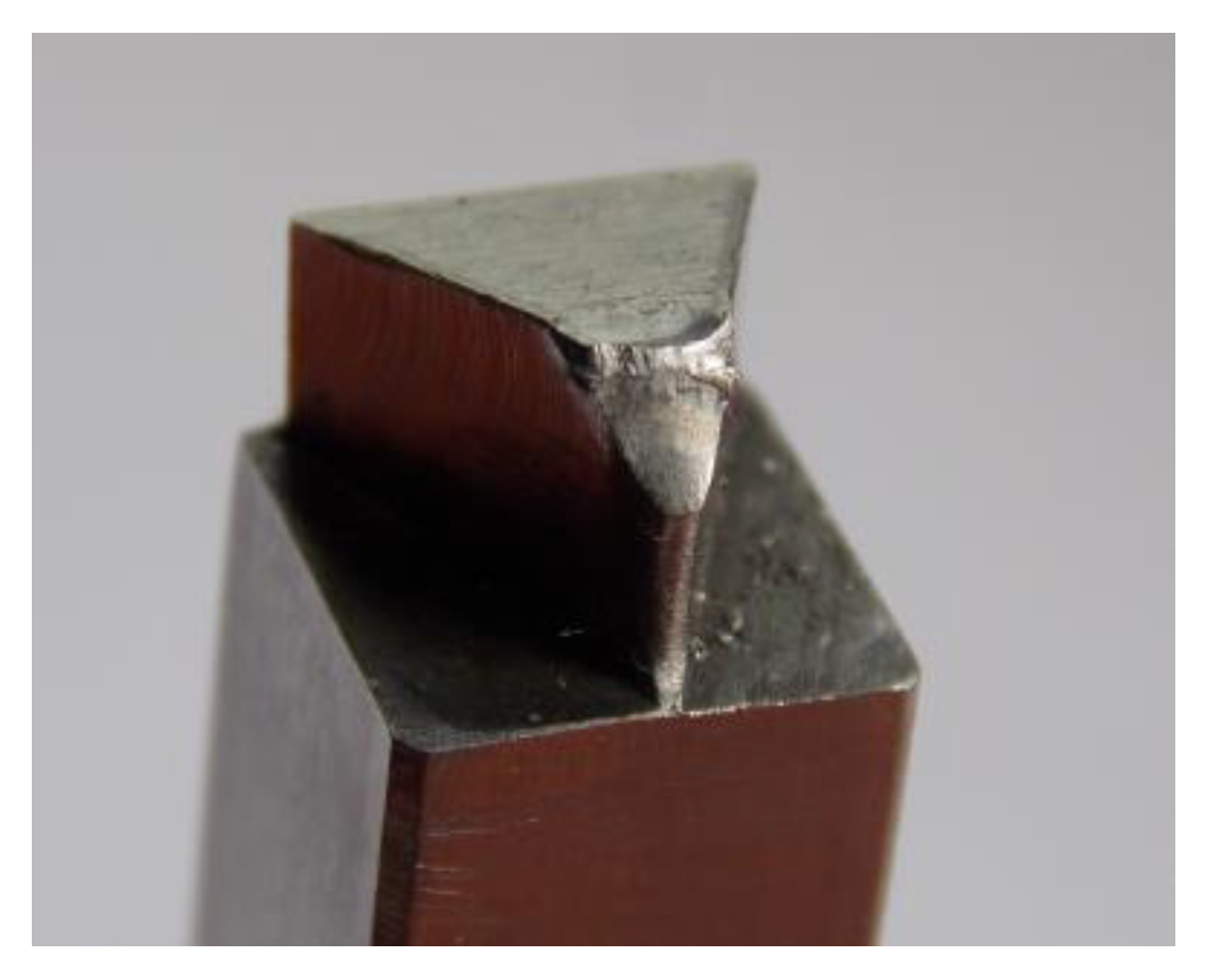
3.3. The Mechanism of Wear and Damage to the Punch
4. Conclusions
Author Contributions
Funding
Acknowledgments
Conflicts of Interest
References
- Falconnet, E.; Chambert, J.; Makich, H.; Monteil, G. Prediction of abrasive punch wear in copper alloy thin sheet blanking. Wear 2015, 338–339, 144–154. [Google Scholar] [CrossRef]
- Romanowski, W.P. Spravochnik po holodnoj shtampovke, 6. Leningrad Mashinostroenie, Leningradskoe otdelenie. 1979, pp. 15–16. Available online: https://spbarchives.ru/infres/-/archive/cgantd/R-53 (accessed on 17 April 2019).
- Cheung, C.F.; Lee, W.B.; Chiu, W.M. An investigation of tool wear in the dam-bar blanking of integrated circuit packages. Wear 2000, 237, 274–282. [Google Scholar] [CrossRef]
- Mucha, J. An experimental analysis of effects of various material tool’s wear on burr during generator sheets blanking. Int. J. Adv. Manuf. Technol. 2010, 5–8, 495–507. [Google Scholar] [CrossRef]
- Mucha, J.; Jaworski, J. The Quality Issue of the parts blanked from thin silicon sheets. J. Mater. Eng. Perform. 2017, 4, 1865–1877. [Google Scholar] [CrossRef]
- Mucha, J.; Jaworski, J. The tool surface wear during the silicon steel sheets blanking process. Eksploat Niezawodn 2016, 3, 332–342. [Google Scholar] [CrossRef]
- Akyürek, F.; Yaman, K.; Tekiner, Z. An experimental work on tool wear affected by die clearance and punch hardness. Arab. J. Sci. Eng. 2017, 42, 4683–4692. [Google Scholar] [CrossRef]
- Subramonian, S.; Altan, T.; Ciocirlan, B.; Campbell, C. Optimum selection of variable punch-die clearance to improve tool life in blanking non-symmetric shapes. Int. J. Mach. Tools Manuf. 2013, 75, 63–71. [Google Scholar] [CrossRef]
- Guo, W.; Tam, H.-Y. Effects of extended punching on wear of the WC/Co micropunch and the punched microholes. Int. J. Adv. Manuf. Technol. 2012, 9–12, 955–960. [Google Scholar] [CrossRef]
- Lawanwong, K.; Pumchan, W. Wear mechanism and ability for recovery of tool steel on blanking die process. Key Eng. Mater. 2017, 725, 572–577. [Google Scholar] [CrossRef]
- Högman, B. Steel for Press Tools: Blanking of Ultra High Strength Steel Sheet. In Proceedings of the 6th International Tooling Conference: The use of tool steels: Experience and research, Karlstad, Sweden, 10–13 September 2002; pp. 237–253. [Google Scholar]
- Makich, H.; Carpentier, L.; Monteil, G.; Roizard, X.; Chambert, J.; Picart, P. Metrology of the burr amount - correlation with blanking operation parameters (blanked material – wear of the punch). Int. J. Mater. Form. 2008, 1, 1243–1246. [Google Scholar]
- Tekiner, Z.; Nalbant, M.; Gurun, H. An experimental study for the effect of different clearances on burr, smooth-sheared and blanking force on aluminium sheet metal. Mater. Design 2006, 27, 1134–1138. [Google Scholar] [CrossRef]
- Hambli, R.; Richir, S.; Crubleau, P.; Taravel, B. Prediction of optimum clearance in sheet metal blanking processes. Int. J. Adv. Manuf. Technol. 2003, 1, 20–25. [Google Scholar] [CrossRef]
- Taupin, E.; Breitling, J.; Wu, W.; Altan, T. Material fracture and burr formation in blanking results of FEM simulations and comparison with experiments. J. Mater. Process. Technol. 1996, 1, 68–78. [Google Scholar] [CrossRef]
- Hatanaka, N.; Yamaguchi, K.; Takakura, N.; Iizuka, T. Simulation of sheared edge formation process in blanking of sheet metals. J. Mater. Process. Technol. 2003, 1–3, 628–634. [Google Scholar] [CrossRef]
- Zhang, J. Numerical study of the effect of tool wear on burr formation in blanking process. Adv. Mat. Res. 2008, 53–54, 95–100. [Google Scholar] [CrossRef]
- Klocke, F. Manufacturing Processes 4: Forming; RWTHedition; Springer Book: Aachen, Germany, 2013. [Google Scholar]
- Gürün, H.; Göktaş, M.; Güldaş, A. Experimental examination of effects of punch angle and clearance on shearing force and estimation of shearing force using fuzzy logic. T. Famena 2016, XL--3, 19–28. [Google Scholar]
- Lin, J.-C.; Lee, K.-S.; Lin, W.-S. The optimal design of micro-punching die by using abductive and SA methods. Arch. Comput. Mat. Sci. Surf. Eng. 2009, 1–2, 92–99. [Google Scholar]
- Podgornik, B.; Zajec, B.; Bay, N.; Viˇzintin, J. Application of hard coatings for blanking and piercing tools. Wear 2011, 270, 850–856. [Google Scholar] [CrossRef]
- Slavič, J.; Bolka, Š.; Bratuš, V.; Boltežar, M. A novel laboratory blanking apparatus for the experimental identification of blanking parameters. J. Mater. Process. Technol. 2014, 2, 507–513. [Google Scholar] [CrossRef]
- Fazily, P.; Yu, J.; Lee, C.-W. Characterization of sheared edges in warm blanking of magnesium alloy AZ31B. Materials 2019, 12, 23. [Google Scholar] [CrossRef]
- So, H.; Faßmann, D.; Hoffmann, H.; Golle, R.; Schaper, M. An investigation of the blanking process of the quenchable boron alloyed steel 22MnB5 before and after hot stamping process. J. Mater. Process. Technol. 2012, 212, 437–449. [Google Scholar] [CrossRef]
- Li, M. An experimental investigation on cut surface and burr in trimming aluminum autobody sheet. Int. J. Mech. Sci. 2000, 5, 889–906. [Google Scholar] [CrossRef]
- Golovashchenko, S.F. A study on trimming of aluminum autobody sheet and development of a new robust process eliminating burrs and slivers. Int. J. Mech. Sci. 2006, 48, 1384–1400. [Google Scholar] [CrossRef]
- Golovashchenko, S.F. Quality of trimming and its effect on stretch flanging of automotive panels. J. Mater. Eng. Perform. 2008, 17, 316–325. [Google Scholar] [CrossRef]
- Wang, N.; Golovashchenko, S.F. Mechanism of fracture of aluminum blanks subjected to stretching along the sheared edge. J. Mater. Process. Technol. 2016, 233, 142–160. [Google Scholar] [CrossRef] [Green Version]
- Golovashchenko, S.F.; Ilinich, A.M. Analysis of trimming processes for advanced high strength steels. SAE Int. J. Mater. Manuf. 2009, 1, 818–823. [Google Scholar] [CrossRef]
- Koppa, T.; Stahl, J.; Demmel, P.; Tröber, P.; Golle, R.; Hoffmann, H.; Volk, W. Experimental investigation of the lateral forces during shear blanking with an open blanking line. J. Mater. Process. Technol. 2016, 238, 49–54. [Google Scholar] [CrossRef]
- Choi, H.S.; Kim, B.M.; Ko, D.C. Effect of clearance and inclined angle on sheared edge and tool failure in trimming of DP980 sheet. J. Mech. Sci. Technol. 2014, 6, 2319–2328. [Google Scholar] [CrossRef]
- Hu, X.H.; Choi, K.S.; Sun, X.; Golovashchenko, S.F. Edge fracture prediction of traditional and advanced trimming processes for AA6111-T4 sheets. J. Manuf. Sci. Eng. 2014, 136, 021016. [Google Scholar] [CrossRef]
- Mackensen, A.; Golle, M.; Golle, R.; Hoffmann, H. Experimental investigation of the blanking force reduction during the blanking operation of AHSS sheet materials. CIRP Ann. Manuf. Technol. 2010, 59, 283–286. [Google Scholar] [CrossRef]
- PN-EN ISO 683-1:2018-09 Heat-Treatable Steels, Alloy Steels and Free-Blanking Steels - Part 1: Non-Alloy 397 Steels for Quenching and Tempering; ISO: Geneva, Switzerland, 2016.
- Cold work tool steel. Available online: https://www.bohler-edelstahl.com/media/K340DE_ISODUR.pdf (accessed on 15 March 2019).


| C | Mn | P | Cr | Si | S | Ni | Mo | Fe |
|---|---|---|---|---|---|---|---|---|
| 0.48 | 0.73 | 0.011 | 0.09 | 0.35 | 0.01 | 0.02 | 0.002 | other |
| Yield Strength Re [MPa] | Tensile Strength Rm [MPa] | Elongation A5 [%] | Hardness HRC |
|---|---|---|---|
| 335 | 2285 | 30 | 55 |
| C | Si | Mn | Cr | Mo | V | Other Micro-Alloying |
|---|---|---|---|---|---|---|
| 1.10 | 0.90 | 0.40 | 8.30 | 2.10 | 0.50 | Al, Nb |
| Number of Cuts | Clearance, C | Clearance, C | ||||
|---|---|---|---|---|---|---|
| 5% | 10% | 15% | 5% | 10% | 15% | |
| Rb [mm] | Hb [mm] | |||||
| First cuts | 13.15 | 13.52 | 14.05 | 1.96 | 1.42 | 1.21 |
| 30,000 | 13.92 | 14.01 | 14.61 | 2.11 | 1.52 | 1.36 |
| 60,000 | 15.75 | 15.77 | 15.71 | 2.12 | 1.67 | 1.28 |
© 2019 by the authors. Licensee MDPI, Basel, Switzerland. This article is an open access article distributed under the terms and conditions of the Creative Commons Attribution (CC BY) license (http://creativecommons.org/licenses/by/4.0/).
Share and Cite
Mucha, J.; Tutak, J. Analysis of the Influence of Blanking Clearance on the Wear of the Punch, the Change of the Burr Size and the Geometry of the Hook Blanked in the Hardened Steel Sheet. Materials 2019, 12, 1261. https://doi.org/10.3390/ma12081261
Mucha J, Tutak J. Analysis of the Influence of Blanking Clearance on the Wear of the Punch, the Change of the Burr Size and the Geometry of the Hook Blanked in the Hardened Steel Sheet. Materials. 2019; 12(8):1261. https://doi.org/10.3390/ma12081261
Chicago/Turabian StyleMucha, Jacek, and Jacek Tutak. 2019. "Analysis of the Influence of Blanking Clearance on the Wear of the Punch, the Change of the Burr Size and the Geometry of the Hook Blanked in the Hardened Steel Sheet" Materials 12, no. 8: 1261. https://doi.org/10.3390/ma12081261