Advanced Electric Discharge Machining of Stainless Steels: Assessment of the State of the Art, Gaps and Future Prospect

 , ,
, ,  and
and
Abstract
:1. Introduction
2. General View of the EDM Method
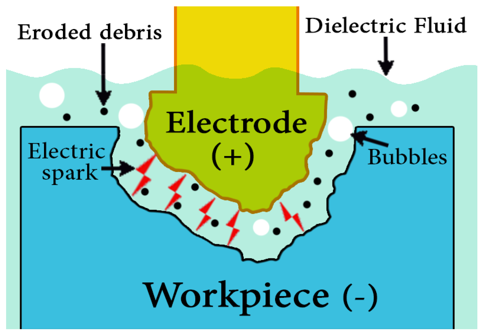
2.1. EDM Principles
2.2. EDM Process Parameters
2.3. Performance Measure Parameters
2.4. Types of EDM Processes
2.4.1. Die-Sinking EDM
2.4.2. Wire EDM
2.4.3. Micro EDM
2.4.4. Powder-Mixed EDM
2.4.5. Dry EDM
2.5. Mathematical Modeling of the Thermos-Physical Phenomenon in EDM
3. Different Stainless Steel Grades
4. Research on EDM of Stainless Steel
4.1. Performance Measures for the EDM of Stainless Steel
4.2. Electrode Tool Shape and Movement Research in the EDM of Stainless Steel
4.3. Layer Machining Research of Stainless Steel
4.4. Combined and Hybrid Processes for Stainless Steel
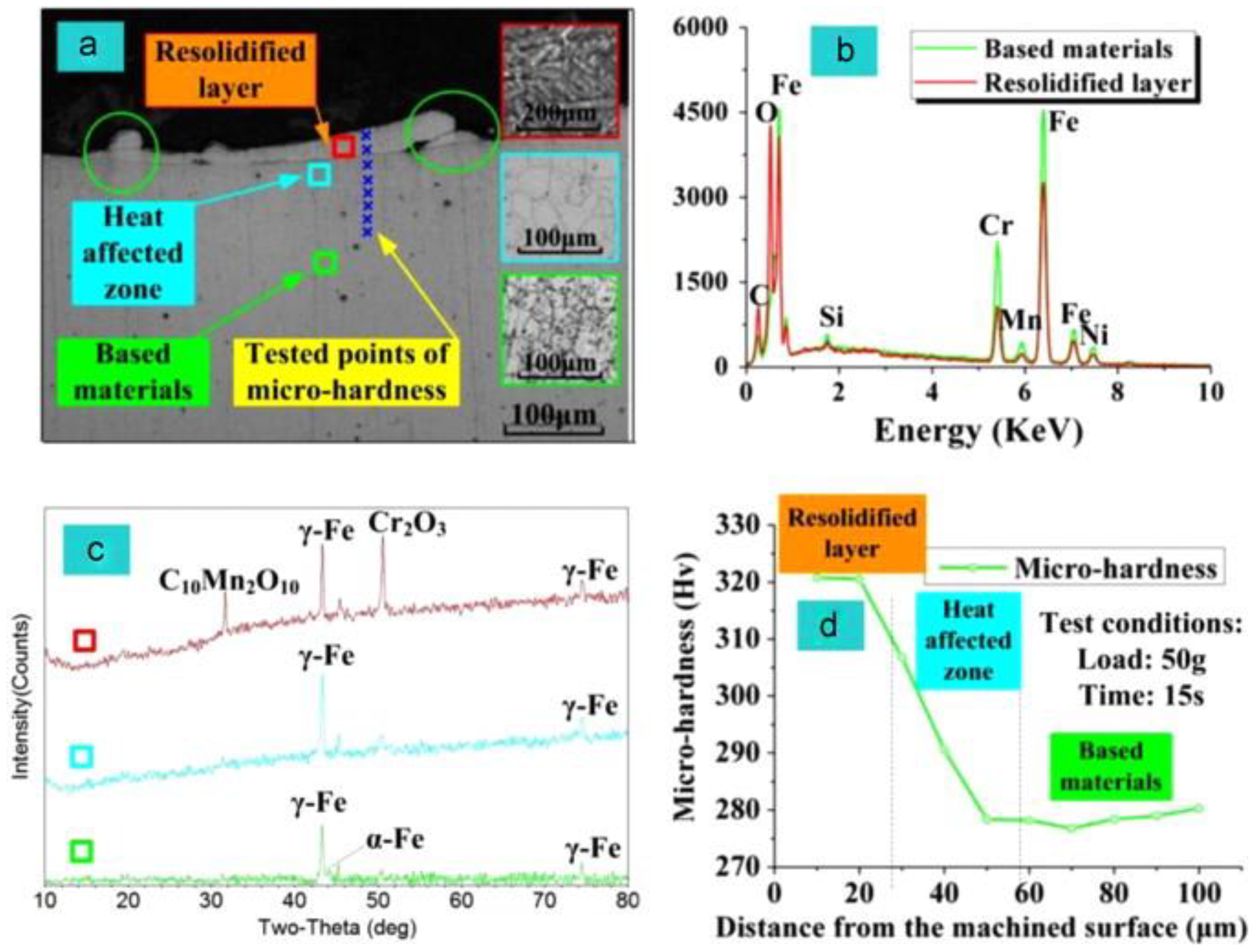
4.5. Effect of the EDM Process on the Properties of Stainless Steel and the Machined Surface
4.6. Dielectric Fluid Research
4.7. Other Research on Stainless Steel and EDM
5. Discussion
6. Conclusions
- A number of research studies have been carried out in the field of EDM and significant improvements in the properties of the machined surfaces have been reported.
- Despite promising results, EDM processes for new materials used in industry still have problems, including low MRR and high TWR. These issues require further investigation.
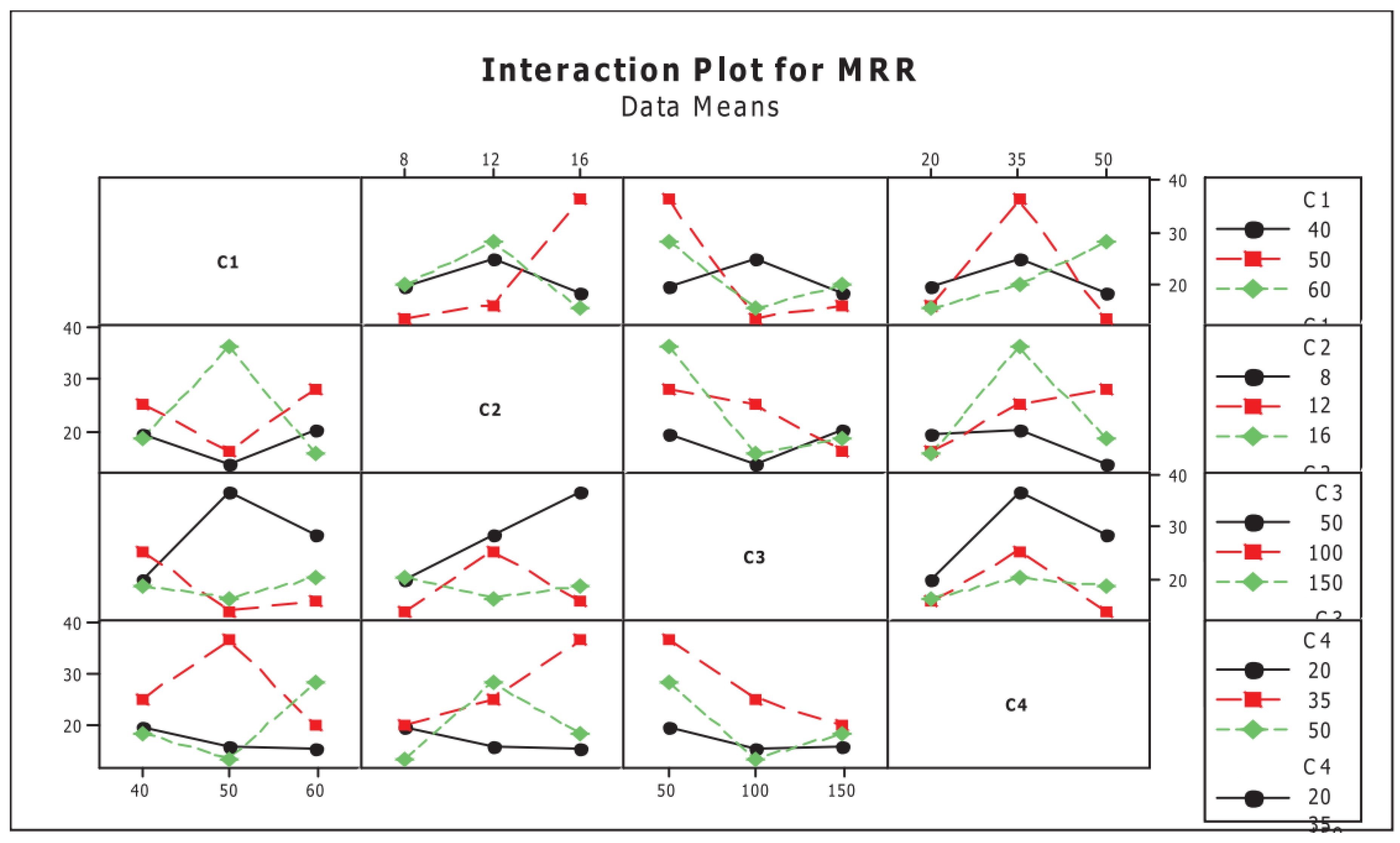
- The reported results generally agree, for machining different stainless steel grades on the EDM the main factor influencing the MRR is the discharge current. However, pulse duration time, gas pressure and electrode tool rotation speed also have a significant influence on the MRR and the MRR can be further improved by using strip-EDM instead of wire-EDM.
- The review reveals that the main parameters influencing the EWR are the discharge current and pulse duration time.
- The reports generally agree that the SR decreases and better surface finish was achieved, with lower values of pulsed current and pulse-on time and relatively higher pulse-off time. High quality SR cannot be achieved where long-duration pulses are used during the finish machining.
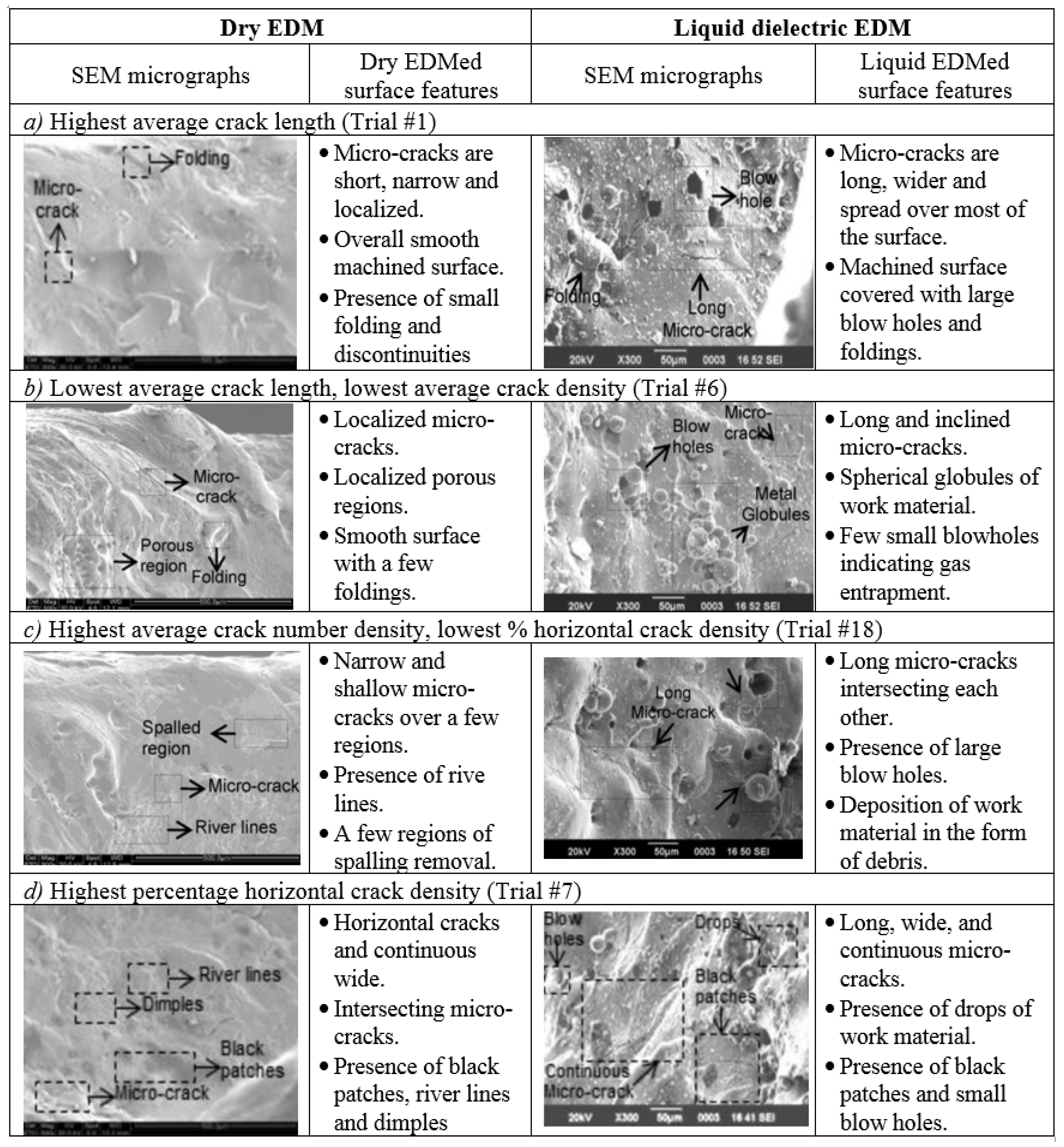
- The review reveals that the crack length is significantly influenced by voltage, current, pulse off-time and speed in the wall and bottom regions of holes machined using dry EDM.
- The review also reveals that workpiece vibration caused by ultrasonic action can improve the performance and efficiency of the micro-EDM process by many times compared to the EDM processes without ultrasonic vibration.
- Applying a magnetic field can improve the geometric and surface quality in the dry EDM process. Using a magnetic field can also lead to a higher transfer of thermal energy to the workpiece and improves the removal of melted material with the dry EDM.
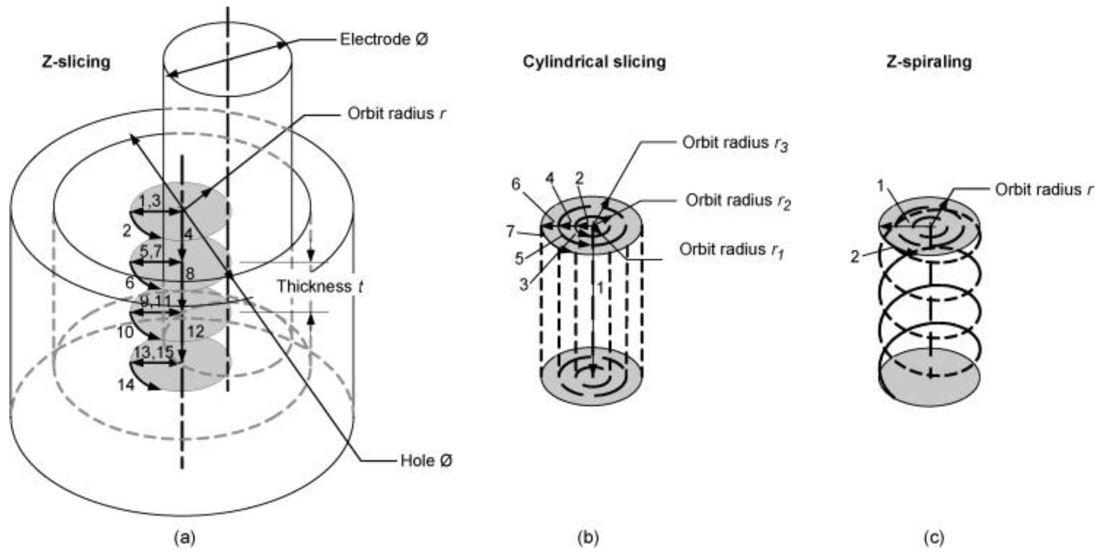
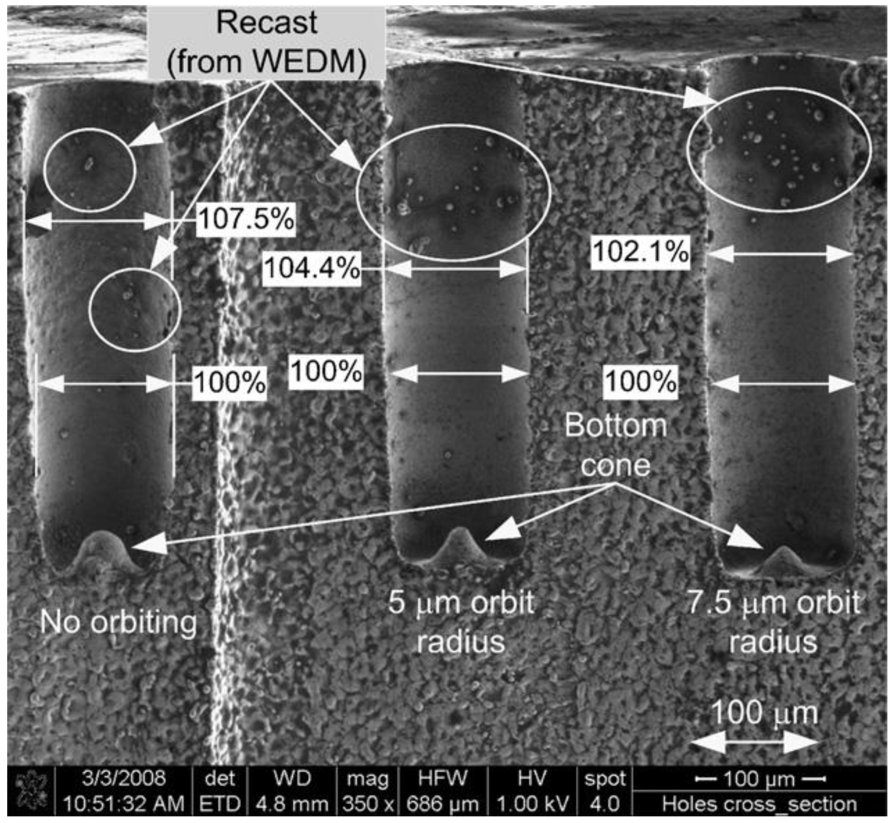
- The orbiting technique provides more uniform geometries of the machined hole and greatly improves the bottom quality for blind holes. The technique also reduces the tooling needs and the electrode tool wear but increases machining times.
- Most researchers paid attention to parameter optimization rather than process improvement or innovation.
- A general observation by the researchers was that the use of electro-rheological fluid can improve SR. Further improvements in the SR can be achieved if electro-rheological fluid is mixed with abrasive powder. There are few existing studies on this topic and more studies are needed to investigate the effect of adding different powders to the EDM of stainless steel.
- Much deeper and more accurate micro-holes can be machined and lower tool wear ratios can be achieved using a high spindle speed.
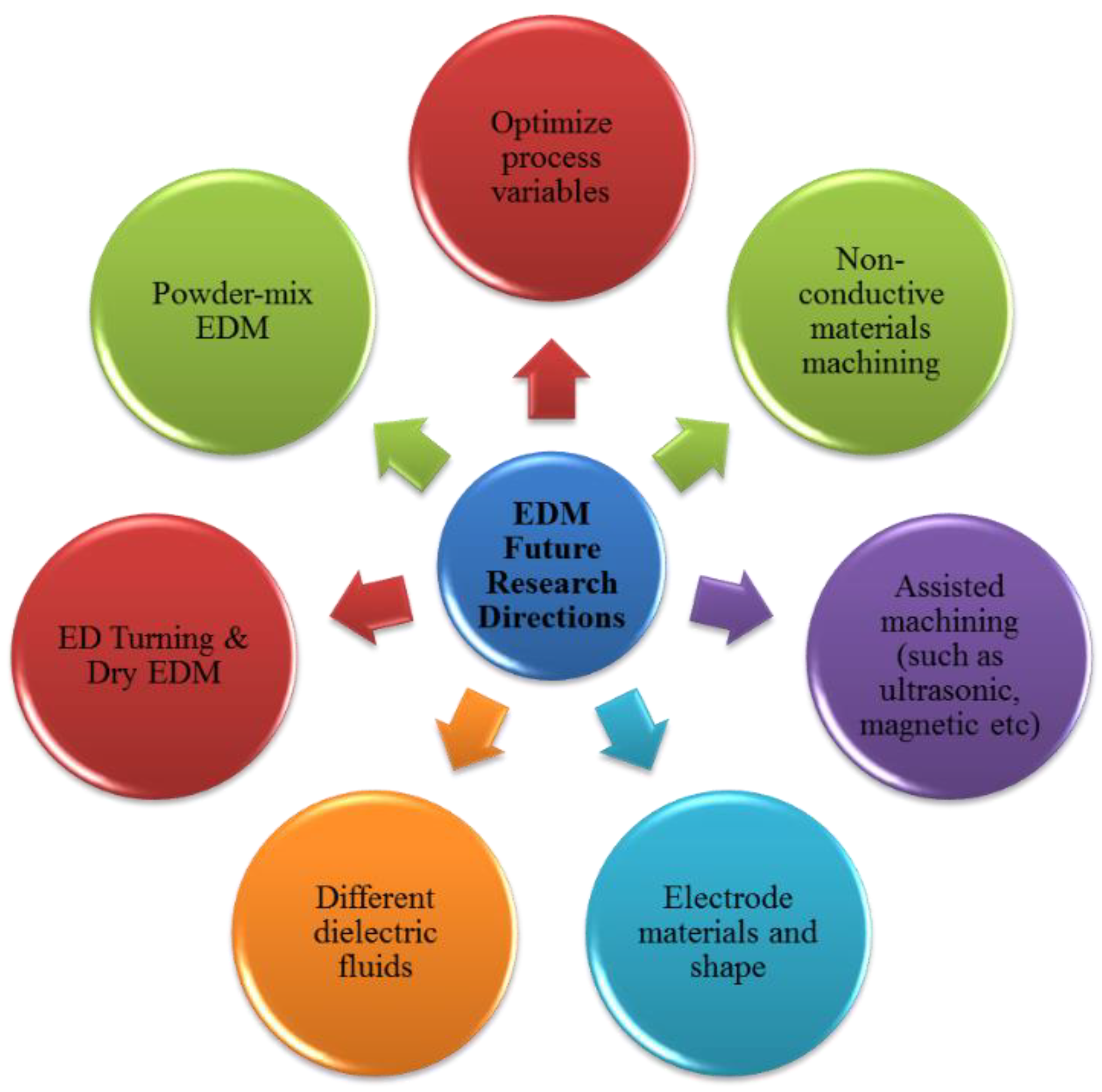
7. Future Research Directions
- Optimizing Process Parameters. The EDM process has a very complex nature due to the complicated discharge mechanisms and their interactions and this makes it difficult to globally optimize the process. The advent of new materials always makes parameter optimization a hot research area and as new grades of stainless steel are introduced frequently, so more investigations are required.
- Extending EDM to a wider range of workpiece materials. EDM is used mainly for conductive materials, however, there is a current trend to explore the possibilities of machining non-conductive or semi-conductive materials such as ceramics, using EDM.
- Use of different electrode tools. Researchers can investigate the performance of the EDM process by using electrode tools of different materials, shape, size and geometry. Use of tubular electrode tools is in its infancy but has already provided promising results, it requires further attention.
- Electrode tool cooling methods. Electrode tool cooling is another research field of potential benefit. Cryogenic cooling of electrode tool has provided positive results in terms of reduction in TWR.
- Hybrid or assisted EDM. The EDM process hybridized with other processes can provide better results than EDM on its own. Magnetic force assisted EDM, laser assisted EDM and so forth, have the potential to overcome many process limitations. For example, ultrasonic assisted EDM showed significant improvement in performance. Research trends may be directed toward the combination of several processes.
- Powder mix EDM. Powders of different materials mixed with dielectrics have been shown to improve the machining process. This is another area which requires further attention and researchers need to address the machining of different stainless steel grades using different EDM processes with dielectric fluids containing different material powders.
Author Contributions
Funding
Conflicts of Interest
References
- Pérez, J.; Llorente, J.; Sanchez, J. Advanced cutting conditions for the milling of aeronautical alloys. J. Mater. Process. Technol. 2000, 100, 1–11. [Google Scholar]
- Komanduri, R.; Hou, Z.-B. On thermoplastic shear instability in the machining of a titanium alloy (Ti-6Al-4V). Metall. Mater. Trans. A 2002, 33, 2995. [Google Scholar] [CrossRef]
- Benes, J. Cutting Difficult Machine Materials. Available online: http://www.Americanmachinist.com/304/Issue/Article (accessed on 24 January 2007).
- Ruszaj, A.; Skoczypiec, S.; Wyszyński, D. Recent developments in abrasive hybrid manufacturing processes. Manag. Prod. Eng. Rev. 2017, 8, 81–90. [Google Scholar] [CrossRef]
- Patel, P.R.B.S.M. A Review of Parametric Optimization of Wire Electric Discharge Machining. Indian J. Appl. Res. 2015, 5, 60–62. [Google Scholar]
- Anonymous. Stainless Steel for Machining, Design Handbook, Design Handbook, Specialty Steel Industry of North America. Available online: http://www.ssina.com/download_a_file/machining.pdf (accessed on 6 February 2019).
- Callister, W.D.; Rethwisch, D.G. Materials Science and Engineering: An Introduction; John Wiley & Sons: New York, NY, USA, 2007; Volume 7. [Google Scholar]
- Chiang, K.-T.; Chang, F.-P. Optimization of the WEDM process of particle-reinforced material with multiple performance characteristics using grey relational analysis. J. Mater. Process. Technol. 2006, 180, 96–101. [Google Scholar] [CrossRef]
- Hewidy, M.; El-Taweel, T.; El-Safty, M. Modelling the machining parameters of wire electrical discharge machining of Inconel 601 using RSM. J. Mater. Process. Technol. 2005, 169, 328–336. [Google Scholar] [CrossRef]
- Kumar, A.; Maheshwari, S.; Sharma, C.; Beri, N. Research developments in additives mixed electrical discharge machining (AEDM): A state of art review. Mater. Manuf. Process. 2010, 25, 1166–1180. [Google Scholar] [CrossRef]
- Lee, S.; Li, X. Study of the effect of machining parameters on the machining characteristics in electrical discharge machining of tungsten carbide. J. Mater. Process. Technol. 2001, 115, 344–358. [Google Scholar] [CrossRef]
- Yu, Z.; Jun, T.; Masanori, K. Dry electrical discharge machining of cemented carbide. J. Mater. Process. Technol. 2004, 149, 353–357. [Google Scholar] [CrossRef]
- Beri, N.; Maheshwari, S.; Sharma, C.; Kumar, A. Technological advancement in electrical discharge machining with powder metallurgy processed electrodes: A review. Mater. Manuf. Process. 2010, 25, 1186–1197. [Google Scholar] [CrossRef]
- Ho, K.; Newman, S.; Rahimifard, S.; Allen, R. State of the art in wire electrical discharge machining (WEDM). Int. J. Mach. Tools Manuf. 2004, 44, 1247–1259. [Google Scholar] [CrossRef]
- Hsieh, M.-F.; Tung, C.-J.; Yao, W.-S.; Wu, M.-C.; Liao, Y.-S. Servo design of a vertical axis drive using dual linear motors for high speed electric discharge machining. Int. J. Mach. Tools Manuf. 2007, 47, 546–554. [Google Scholar] [CrossRef]
- Lim, H.; Wong, Y.; Rahman, M.; Lee, M.E. A study on the machining of high-aspect ratio micro-structures using micro-EDM. J. Mater. Process. Technol. 2003, 140, 318–325. [Google Scholar] [CrossRef]
- Singh, S.; Maheshwari, S.; Pandey, P. Some investigations into the electric discharge machining of hardened tool steel using different electrode materials. J. Mater. Process. Technol. 2004, 149, 272–277. [Google Scholar] [CrossRef]
- Tzeng, Y.-F.; Chen, F.-C. A simple approach for robust design of high-speed electrical-discharge machining technology. Int. J. Mach. Tools Manuf. 2003, 43, 217–227. [Google Scholar] [CrossRef]
- Tzeng, Y.-F.; Chen, F.-C. Multi-objective optimisation of high-speed electrical discharge machining process using a Taguchi fuzzy-based approach. Mater. Des. 2007, 28, 1159–1168. [Google Scholar] [CrossRef]
- Surleraux, A.; Pernot, JP.; Elkaseer, A.; Bigot, S. Iterative surface warping to shape craters in micro-EDM simulation. Eng. Comput. 2016, 32, 517–531. [Google Scholar] [CrossRef] [Green Version]
- Kansal, H.; Singh, S.; Kumar, P. Technology and research developments in powder mixed electric discharge machining (PMEDM). J. Mater. Process. Technol. 2007, 184, 32–41. [Google Scholar] [CrossRef]
- Kumar, S.; Singh, R.; Singh, T.; Sethi, B. Surface modification by electrical discharge machining: A review. J. Mater. Process. Technol. 2009, 209, 3675–3687. [Google Scholar] [CrossRef]
- McCown, B.; McCabe, D.; Russell, D.; Robison, D.; Barton, K.; Raffa, K. Stable transformation of Populus and incorporation of pest resistance by electric discharge particle acceleration. Plant Cell Rep. 1991, 9, 590–594. [Google Scholar] [CrossRef]
- Yan, B.; Huang, F.; Chow, H.; Tsai, J. Micro-hole machining of carbide by electric discharge machining. J. Mater. Process. Technol. 1999, 87, 139–145. [Google Scholar] [CrossRef]
- Guu, Y.; Chou, C.; Chiou, S.-T. Study of the effect of machining parameters on the machining characteristics in electrical discharge machining of Fe-Mn-Al alloy. Mater. Manuf. Process. 2005, 20, 905–916. [Google Scholar] [CrossRef]
- Kansal, H.; Singh, S.; Kumar, P. Numerical simulation of powder mixed electric discharge machining (PMEDM) using finite element method. Math. Comput. Model. 2008, 47, 1217–1237. [Google Scholar] [CrossRef]
- Mahapatra, S.S.; Patnaik, A. Parametric optimization of wire electrical discharge machining (WEDM) process using Taguchi method. J. Braz. Soc. Mech. Sci. Eng. 2006, 28, 422–429. [Google Scholar] [CrossRef]
- Pecas, P.; Henriques, E. Influence of silicon powder-mixed dielectric on conventional electrical discharge machining. Int. J. Mach. Tools Manuf. 2003, 43, 1465–1471. [Google Scholar] [CrossRef]
- Saito, K.; Kishinami, T.; Konno, H.; Sato, M.; Takeyama, H. Development of numerical contouring control electric discharge machining (NCC-EDM). CIRP Ann. 1986, 35, 117–120. [Google Scholar] [CrossRef]
- Sohani, M.; Gaitonde, V.; Siddeswarappa, B.; Deshpande, A. Investigations into the effect of tool shapes with size factor consideration in sink electrical discharge machining (EDM) process. Int. J. Adv. Manuf. Technol. 2009, 45, 1131. [Google Scholar] [CrossRef]
- Haddad, M.; Tajik, M.; Tehrani, A.F.; Mohammadi, A.; Hadi, M. An experimental investigation of cylindrical wire electrical discharge turning process using Taguchi approach. Int. J. Mater. Form. 2009, 2, 167–179. [Google Scholar] [CrossRef]
- Joshi, S.; Pande, S. Intelligent process modeling and optimization of die-sinking electric discharge machining. Appl. Soft Comput. 2011, 11, 2743–2755. [Google Scholar] [CrossRef]
- Chakraborty, S.; Dey, V.; Ghosh, S. A review on the use of dielectric fluids and their effects in electrical discharge machining characteristics. Precis. Eng. 2015, 40, 1–6. [Google Scholar] [CrossRef]
- Choudhary, S.K.; Jadoun, R. Current advanced research development of electric discharge machining (EDM): A review. Int. J. Res. Advent Technol. 2014, 2, 273–297. [Google Scholar]
- Garg, R.; Singh, K.; Sachdeva, A.; Sharma, V.S.; Ojha, K.; Singh, S. Review of research work in sinking EDM and WEDM on metal matrix composite materials. Int. J. Adv. Manuf. Technol. 2010, 50, 611–624. [Google Scholar] [CrossRef]
- Jahan, M.; Rahman, M.; Wong, Y. A review on the conventional and micro-electrodischarge machining of tungsten carbide. Int. J. Mach. Tools Manuf. 2011, 51, 837–858. [Google Scholar] [CrossRef]
- Muthuramalingam, T.; Mohan, B. A review on influence of electrical process parameters in EDM process. Arch. Civ. Mech. Eng. 2015, 15, 87–94. [Google Scholar] [CrossRef]
- Rajurkar, K.P.; Sundaram, M.; Malshe, A. Review of electrochemical and electrodischarge machining. Procedia CIRP 2013, 6, 13–26. [Google Scholar] [CrossRef]
- Abu Qudeiri, J.E.; Mourad, A.-H.I.; Ziout, A.; Abidi, M.H.; Elkaseer, A. Electric discharge machining of titanium and its alloys. Int. J. Adv. Manuf. Technol. 2018, 96, 1319–1339. [Google Scholar] [CrossRef]
- Dauw, D.; Snoeys, R.; Dekeyser, W. Advanced pulse discriminating system for EDM process analysis and control. CIRP Ann. 1983, 32, 541–549. [Google Scholar] [CrossRef]
- Gao, C.; Liu, Z. A study of ultrasonically aided micro-electrical-discharge machining by the application of workpiece vibration. J. Mater. Process. Technol. 2003, 139, 226–228. [Google Scholar] [CrossRef]
- Gostimirovic, M.; Kovac, P.; Skoric, B.; Sekulic, M. Effect of electrical pulse parameters on the machining performance in EDM. Indian J. Eng. Mater. Sci. 2011, 18, 411–415. [Google Scholar]
- Schulze, H.P. Energetic consideration of the spark erosion using different process energy sources and pulse-unit-gap conditions. Key Eng. Mater. 2015, 701–706. [Google Scholar] [CrossRef]
- Marafona, J.; Chousal, J. A finite element model of EDM based on the Joule effect. Int. J. Mach. Tools Manuf. 2006, 46, 595–602. [Google Scholar] [CrossRef]
- Abbas, N.M.; Solomon, D.G.; Bahari, M.F. A review on current research trends in electrical discharge machining (EDM). Int. J. Mach. Tools Manuf. 2007, 47, 1214–1228. [Google Scholar] [CrossRef]
- Cui, J.; Chu, Z. Composite motion design procedure for vibration assisted small-hole EDM using one voice coil motor. Shock Vib. 2016, 2016, 4179296. [Google Scholar] [CrossRef]
- Ho, K.; Newman, S. State of the art electrical discharge machining (EDM). Int. J. Mach. Tools Manuf. 2003, 43, 1287–1300. [Google Scholar] [CrossRef]
- Shen, Y.; Liu, Y.; Zhang, Y.; Dong, H.; Sun, W.; Wang, X.; Zheng, C.; Ji, R. High-speed dry electrical discharge machining. Int. J. Mach. Tools Manuf. 2015, 93, 19–25. [Google Scholar] [CrossRef]
- Anpilov, A.; Barkhudarov, E.; Bark, Y.B.; Zadiraka, Y.V.; Christofi, M.; Kozlov, Y.N.; Kossyi, I.; Kop’ev, V.; Silakov, V.; Taktakishvili, M. Electric discharge in water as a source of UV radiation, ozone and hydrogen peroxide. J. Phys. D Appl. Phys. 2001, 34, 993. [Google Scholar] [CrossRef]
- Grigoryev, E.G.; Olevsky, E.A. Thermal processes during high-voltage electric discharge consolidation of powder materials. Scr. Mater. 2012, 66, 662–665. [Google Scholar] [CrossRef]
- Huang, S.; Liu, Y.; Li, J.; Hu, H.; Sun, L. Electrochemical discharge machining micro-hole in stainless steel with tool electrode high-speed rotating. Mater. Manuf. Process. 2014, 29, 634–637. [Google Scholar] [CrossRef]
- Ikonomou, M.G.; Blades, A.T.; Kebarle, P. Electrospray mass spectrometry of methanol and water solutions suppression of electric discharge with SF 6 gas. J. Am. Soc. Mass Spectrom. 1991, 2, 497–505. [Google Scholar] [CrossRef]
- Singh, V.; Bhandari, R.; Yadav, V.K. An experimental investigation on machining parameters of AISI D2 steel using WEDM. Int. J. Adv. Manuf. Technol. 2017, 93, 203–214. [Google Scholar] [CrossRef]
- Sun, B.; Sato, M.; Clements, J.S. Use of a pulsed high-voltage discharge for removal of organic compounds in aqueous solution. J. Phys. D Appl. Phys. 1999, 32, 1908. [Google Scholar] [CrossRef]
- Rajmohan, K.; Kumar, A.S. Experimental investigation and prediction of optimum process parameters of micro-wire-cut EDM of 2205 DSS. Int. J. Adv. Manuf. Technol. 2017, 93, 187–201. [Google Scholar] [CrossRef]
- Jegan, T.C.; Anand, M.D.; Ravindran, D. Determination of electro discharge machining parameters in AISI202 stainless steel using grey relational analysis. Procedia Eng. 2012, 38, 4005–4012. [Google Scholar] [CrossRef]
- Kuppan, P.; Rajadurai, A.; Narayanan, S. Influence of EDM process parameters in deep hole drilling of Inconel 718. Int. J. Adv. Manuf. Technol. 2008, 38, 74–84. [Google Scholar] [CrossRef]
- Lajis, M.A.; Radzi, H.; Amin, A. The implementation of Taguchi method on EDM process of tungsten carbide. Eur. J. Sci. Res. 2009, 26, 609–617. [Google Scholar]
- Lin, Y.C.; Yan, B.H.; Chang, Y.S. Machining characteristics of titanium alloy (Ti–6Al–4V) using a combination process of EDM with USM. J. Mater. Process. Technol. 2000, 104, 171–177. [Google Scholar] [CrossRef]
- Liu, Y.; Guo, Y.; Liu, J. Electric discharge milling of polycrystalline diamond. Proc. Inst. Mech. Eng. Part B J. Eng. Manuf. 1997, 211, 643–647. [Google Scholar] [CrossRef]
- Singh, H.; Garg, R. Effects of process parameters on material removal rate in WEDM. J. Achiev. Mater. Manuf. Eng. 2009, 32, 70–74. [Google Scholar]
- Bhattacharyya, B.; Munda, J. Experimental investigation on the influence of electrochemical machining parameters on machining rate and accuracy in micromachining domain. Int. J. Mach. Tools Manuf. 2003, 43, 1301–1310. [Google Scholar] [CrossRef]
- Lin, C.; Lin, J.; Ko, T. Optimisation of the EDM process based on the orthogonal array with fuzzy logic and grey relational analysis method. Int. J. Adv. Manuf. Technol. 2002, 19, 271–277. [Google Scholar] [CrossRef]
- Lin, J.; Wang, K.; Yan, B.; Tarng, Y. Optimization of the electrical discharge machining process based on the Taguchi method with fuzzy logics. J. Mater. Process. Technol. 2000, 102, 48–55. [Google Scholar] [CrossRef]
- Ramakrishnan, R.; Karunamoorthy, L. Modeling and multi-response optimization of Inconel 718 on machining of CNC WEDM process. J. Mater. Process. Technol. 2008, 207, 343–349. [Google Scholar] [CrossRef]
- Selvakumar, G.; Jiju, K.B.; Veerajothi, R. Experimental study on wire electrical discharge machining of tapered parts. ARAB. J. Sci. Eng. 2016, 41, 4431–4439. [Google Scholar] [CrossRef]
- Sharif, S.; Safiei, W.; Mansor, A.; Isa, M.; Saad, R. Experimental study of electrical discharge machine (die sinking) on stainless steel 316L using design of experiment. Procedia Manuf. 2015, 2, 147–152. [Google Scholar] [CrossRef]
- Kansal, H.; Singh, S.; Kumar, P. Parametric optimization of powder mixed electrical discharge machining by response surface methodology. J. Mater. Process. Technol. 2005, 169, 427–436. [Google Scholar] [CrossRef]
- Muthuramalingam, T.; Mohan, B. Influence of discharge current pulse on machinability in electrical discharge machining. Mater. Manuf. Process. 2013, 28, 375–380. [Google Scholar] [CrossRef]
- Pattnaik, S.; Priyadarshini, M.; Mahapatra, K.; Mishra, D.; Panda, S. Multi objective optimization of EDM process parameters using fuzzy TOPSIS method. In Proceedings of the 2015 International Conference on Innovations in Information, Embedded and Communication Systems (ICIIECS), Coimbatore, India, 19–20 March 2015; pp. 1–5. [Google Scholar]
- Rajurkar, K.P.; Wang, W.M. Improvement of EDM Performance With Advanced Monitoring and Control Systems. J. Mech. Des. 1997, 119, 770. [Google Scholar] [CrossRef]
- Fuller, J.E. Electrical discharge machining. ASM Handb. 1989, 16, 557–564. [Google Scholar]
- De Bruyn, H. Slope Control: A great improvement in spark erosion. Ann. CIRP 1967, 16, 183–191. [Google Scholar]
- Lin, Y.-C.; Chen, Y.-F.; Wang, D.-A.; Lee, H.-S. Optimization of machining parameters in magnetic force assisted EDM based on Taguchi method. J. Mater. Process. Technol. 2009, 209, 3374–3383. [Google Scholar] [CrossRef]
- Pandit, S.; Mueller, T. Verification of on-line computer control of EDM by data dependent systems. J. Eng. Ind. 1987, 109, 117–121. [Google Scholar] [CrossRef]
- Lingadurai, K.; Nagasivamuni, B.; Kamatchi, M.M.; Palavesam, J. Selection of wire electrical discharge machining process parameters on stainless steel AISI grade-304 using design of experiments approach. J. Inst. Eng. (India) Ser. C 2012, 93, 163–170. [Google Scholar] [CrossRef]
- Majumder, A. Process parameter optimization during EDM of AISI 316 LN stainless steel by using fuzzy based multi-objective PSO. J. Mech. Sci. Technol. 2013, 27, 2143–2151. [Google Scholar] [CrossRef]
- Marafona, J.; Wykes, C. A new method of optimising material removal rate using EDM with copper–tungsten electrodes. Int. J. Mach. Tools Manuf. 2000, 40, 153–164. [Google Scholar] [CrossRef]
- Su, J.; Kao, J.; Tarng, Y. Optimisation of the electrical discharge machining process using a GA-based neural network. Int. J. Adv. Manuf. Technol. 2004, 24, 81–90. [Google Scholar] [CrossRef]
- Mohan, B.; Rajadurai, A.; Satyanarayana, K. Effect of SiC and rotation of electrode on electric discharge machining of Al–SiC composite. J. Mater. Process. Technol. 2002, 124, 297–304. [Google Scholar] [CrossRef]
- Mohan, B.; Rajadurai, A.; Satyanarayana, K. Electric discharge machining of Al–SiC metal matrix composites using rotary tube electrode. J. Mater. Process. Technol. 2004, 153, 978–985. [Google Scholar] [CrossRef]
- Wilson, C. Investigations on lightning discharges and on the electric field of thunderstorms. Mon. Weather Rev. 1921, 49, 241. [Google Scholar] [CrossRef]
- Crookall, J.; Heuvelman, C. Electro-discharge machining—The state of the art. Ann. CIRP 1971, 20, 113–120. [Google Scholar]
- Liao, Y.-S.; Chuang, T.-J.; Yu, Y.-P. Study of machining parameters optimization for different materials in WEDM. Int. J. Adv. Manuf. Technol. 2014, 70, 2051–2058. [Google Scholar] [CrossRef]
- Jahan, M.P.; Wong, Y.S.; Rahman, M. A study on the quality micro-hole machining of tungsten carbide by micro-EDM process using transistor and RC-type pulse generator. J. Mater. Process. Technol. 2009, 209, 1706–1716. [Google Scholar] [CrossRef]
- Natarajan, N.; Suresh, P. Experimental investigations on the microhole machining of 304 stainless steel by micro-EDM process using RC-type pulse generator. Int. J. Adv. Manuf. Technol. 2015, 77, 1741–1750. [Google Scholar] [CrossRef]
- Han, F.; Chen, L.; Yu, D.; Zhou, X. Basic study on pulse generator for micro-EDM. Int. J. Adv. Manuf. Technol. 2007, 33, 5–6. [Google Scholar] [CrossRef]
- Tsai, Y.; Tseng, C.; Chang, C. Development of a combined machining method using electrorheological fluids for EDM. J. Mater. Process. Technol. 2008, 201, 565–569. [Google Scholar] [CrossRef]
- Valaki, J.B.; Rathod, P.P. Assessment of operational feasibility of waste vegetable oil based bio-dielectric fluid for sustainable electric discharge machining (EDM). Int. J. Adv. Manuf. Technol. 2016, 87, 1509–1518. [Google Scholar] [CrossRef]
- Fujiki, M.; Ni, J.; Shih, A.J. Investigation of the effects of electrode orientation and fluid flow rate in near-dry EDM milling. Int. J. Mach. Tools Manuf. 2009, 49, 749–758. [Google Scholar] [CrossRef]
- Lonardo, P.; Bruzzone, A. Effect of flushing and electrode material on die sinking EDM. CIRP Ann.-Manuf. Technol. 1999, 48, 123–126. [Google Scholar] [CrossRef]
- Wong, Y.; Lim, L.; Lee, L. Effects of flushing on electro-discharge machined surfaces. J. Mater. Process. Technol. 1995, 48, 299–305. [Google Scholar] [CrossRef]
- Anonymous. Dielectric Fluids for Electro Dischargemachining; British Petroleum Company: London, UK, 1982. [Google Scholar]
- Guu, Y.; Hocheng, H. Effects of workpiece rotation on machinability during electrical-discharge machining. Mater. Manuf. Process. 2001, 16, 91–101. [Google Scholar] [CrossRef]
- Soni, J.S.; Chakraverti, G. Machining characteristics of titanium with rotary electro-discharge machining. Wear 1994, 171, 51–58. [Google Scholar] [CrossRef]
- Kagaya, K.; Ōishi, Y.; Yada, K. Micro-electrodischarge machining using water as a working fluid—I: Micro-hole drilling. Precis. Eng. 1986, 8, 157–162. [Google Scholar] [CrossRef]
- Sato, T.; Mizutani, T.; Yonemochi, K.; Kawata, K. The development of an electrodischarge machine for micro-hole boring. Precis. Eng. 1986, 8, 163–168. [Google Scholar] [CrossRef]
- Yan, B.; Wang, C.; Liu, W.; Huang, F. Machining characteristics of Al2O3/6061Al composite using rotary EDM with a disklike electrode. Int. J. Adv. Manuf. Technol. 2000, 16, 322–333. [Google Scholar] [CrossRef]
- Bayramoglu, M.; Duffill, A. Manufacturing linear and circular contours using CNC EDM and frame type tools. Int. J. Mach. Tools Manuf. 1995, 35, 1125–1136. [Google Scholar] [CrossRef]
- Erden, A. Effect of materials on the mechanism of electric discharge machining (EDM). J. Eng. Mater. Technol. 1983, 105, 132–138. [Google Scholar] [CrossRef]
- KANEKO, T.; TSUCHIYA, M. Three-dimensionally controlled EDM Using a cylindrical electrode (5th report). J. Jpn. Soc. Electr. Mach. Eng. 1985, 18, 1–16. [Google Scholar]
- Roethel, F.; Kosec, L.; Garbajs, V. Contribution to the MICRO-analysis of the Spark Eroded Surfaces. CIRP Ann. CIRP 1976, 25, 135–140. [Google Scholar]
- Soni, J.; Chakraverti, G. Experimental investigation on migration of material during EDM of die steel (T215 Cr12). J. Mater. Process. Technol. 1996, 56, 439–451. [Google Scholar] [CrossRef]
- Mohri, N.; Suzuki, M.; Furuya, M.; Saito, N.; Kobayashi, A. Electrode wear process in electrical discharge machinings. CIRP Ann. 1995, 44, 165–168. [Google Scholar] [CrossRef]
- Staelens, F.; Kruth, J.-P. A computer integrated machining strategy for planetary EDM. CIRP Ann. 1989, 38, 187–190. [Google Scholar] [CrossRef]
- Schumacher, B. EDM technology for precision workpieces with excellent surface quality. Proc. ISEM 1983, 7, 124–135. [Google Scholar]
- Wendorf, D.M.; Milos, M. Things to Consider When Wire and Small-Hole EDMing. 2009, Volume 2. Available online: https://www.xactedm.com/DBfiles/news-file/59.pdf (accessed on 5 February 2019).
- Huang, C.A.; Shih, C.L.; Li, K.C.; Chang, Y.-Z. The surface alloying behavior of martensitic stainless steel cut with wire electrical discharge machine. Appl. Surf. Sci. 2006, 252, 2915–2926. [Google Scholar] [CrossRef]
- Bae, W.-G.; Kim, D.; Song, K.Y.; Jeong, H.E.; Chu, C.N. Engineering stainless steel surface via wire electrical discharge machining for controlling the wettability. Surf. Coat. Technol. 2015, 275, 316–323. [Google Scholar] [CrossRef]
- Furutani, K.; Suzuki, K. Experimental investigations of deposition conditions for saw wire fabrication by electrical discharge machining. Int. J. Adv. Manuf. Technol. 2015, 76, 1643–1651. [Google Scholar] [CrossRef]
- Huang, C.; Tu, G.; Yao, H.; Kuo, H. Characteristics of the rough-cut surface of quenched and tempered martensitic stainless steel using wire electrical discharge machining. Metall. Mater. Trans. A 2004, 35, 1351–1357. [Google Scholar] [CrossRef]
- Masuzawa, T.; Fujino, M.; Kobayashi, K.; Suzuki, T.; Kinoshita, N. Wire electro-discharge grinding for micro-machining. CIRP Ann. 1985, 34, 431–434. [Google Scholar] [CrossRef]
- Sidhom, H.; Ghanem, F.; Amadou, T.; Gonzalez, G.; Braham, C. Effect of electro discharge machining (EDM) on the AISI316L SS white layer microstructure and corrosion resistance. Int. J. Adv. Manuf. Technol. 2013, 65, 141–153. [Google Scholar] [CrossRef]
- Usta, B.K.; Gokdel, Y.; Mutlu, Ş.; Yalcinkaya, A. Selectively thinned stainless steel scanners through electrical discharge machining. In Proceedings of the 16th International Conference on Optical MEMS and Nanophotonics, Istanbul, Turkey, 8–11 August 2011; pp. 179–180. [Google Scholar]
- Pradhan, M. Estimating the effect of process parameters on MRR, TWR and radial overcut of EDMed AISI D2 tool steel by RSM and GRA coupled with PCA. Int. J. Adv. Manuf. Technol. 2013, 68, 591–605. [Google Scholar] [CrossRef]
- Yan, M.-T.; Lai, Y.-P. Surface quality improvement of wire-EDM using a fine-finish power supply. Int. J. Mach. Tools Manuf. 2007, 47, 1686–1694. [Google Scholar] [CrossRef]
- Yi, S.M.; Park, M.S.; Lee, Y.S.; Chu, C.N. Fabrication of a stainless steel shadow mask using batch mode micro-EDM. Microsyst. Technol. 2008, 14, 411–417. [Google Scholar] [CrossRef]
- Jahan, M.P.; San Wong, Y.; Rahman, M. A comparative experimental investigation of deep-hole micro-EDM drilling capability for cemented carbide (WC-Co) against austenitic stainless steel (SUS 304). Int. J. Adv. Manuf. Technol. 2010, 46, 1145–1160. [Google Scholar] [CrossRef]
- Mahendran, S.; Devarajan, R.; Nagarajan, T.; Majdi, A. A Review of Micro-EDM. Proceeding of the International MultiConference of Engineers an Computer Sciences 2010 Vol II, IMECS 2010, Hong Kong, China, 17–19 March 2010. [Google Scholar]
- Rasheed, M.S.; Abidi, M.H.; El-Tamimi, A.M.; Al-Ahmari, A. Investigation of micro-edm input parameters on various outputs in machining ni-ti shape memory alloy using full factorial design. Adv. Mater. Res. 2013, 816–817, 173–179. [Google Scholar] [CrossRef]
- Lappin, D.; Mohammadi, A.R.; Takahata, K. An experimental study of electrochemical polishing for micro-electro-discharge-machined stainless-steel stents. J. Mater. Sci. Mater. Med. 2012, 23, 349–356. [Google Scholar] [CrossRef]
- Habib, M.A.; Rahman, M. Performance analysis of EDM electrode fabricated by localized electrochemical deposition for micro-machining of stainless steel. Int. J. Adv. Manuf. Technol. 2010, 49, 975–986. [Google Scholar] [CrossRef]
- Herzig, M.; Berger, T.; Schulze, H.-P.; Hackert-Oschätzchen, M.; Kröning, O.; Schubert, A. Modification of the process dynamics in micro-EDM by means of an additional piezo-control system. AIP Conf. Proc. 2017, 1896, 050003. [Google Scholar]
- Kuriachen, B.; Somashekhar, K.; Mathew, J. Multiresponse optimization of micro-wire electrical discharge machining process. Int. J. Adv. Manuf. Technol. 2015, 76, 91–104. [Google Scholar] [CrossRef]
- D’Urso, G.; Maccarini, G.; Quarto, M.; Ravasio, C. Investigation on power discharge in micro-EDM stainless steel drilling using different electrodes. J. Mech. Sci. Technol. 2015, 29, 4341–4349. [Google Scholar] [CrossRef]
- D’Urso, G.; Maccarini, G.; Ravasio, C. Influence of electrode material in micro-EDM drilling of stainless steel and tungsten carbide. Int. J. Adv. Manuf. Technol. 2016, 85, 2013–2025. [Google Scholar] [CrossRef]
- Dave, H.; Mathai, V.; Desai, K.; Raval, H. Studies on quality of microholes generated on Al 1100 using micro-electro-discharge machining process. Int. J. Adv. Manuf. Technol. 2015, 76, 127–140. [Google Scholar] [CrossRef]
- Rasheed, M.S.; Al-Ahmari, A.; El-Tamimi, A.; Abidi, M.H. Analysis of influence of micro-EDM parameters on MRR, TWR and Ra in machining Ni-Ti shape memory alloy. Int. J. Recent Technol. Eng. 2012, 1, 32–37. [Google Scholar]
- Jafferson, J.; Hariharan, P.; Kumar, J.R. Effect of non-electrical parameters in μED milling: An experimental investigation. Int. J. Adv. Manuf. Technol. 2016, 85, 2037–2047. [Google Scholar] [CrossRef]
- Liu, Q.Y.; Zhang, Q.H.; Zhang, J.H.; Zhang, M. Influence of Grain Size and Grain Boundary of Workpiece on Micro EDM. Adv. Mater. Res. 2014, 941–944, 2116–2120. [Google Scholar] [CrossRef]
- Liu, Q.; Zhang, Q.; Zhang, M.; Zhang, J. Effects of grain size of AISI 304 on the machining performances in micro electrical discharge machining. Proc. Inst. Mech. Eng. Part B J. Eng. Manuf. 2017, 231, 359–366. [Google Scholar] [CrossRef]
- Elkaseer, A.; Bigot, S.; Surleraux, A.; Rosochowski, A. Effect of material microstructure on the micro-EDM process. In Proceedings of the the 8th International Conference on Micro Manufacturing (ICOMM2013), Victoria, BC, Canada, 25–28 March 2013; pp. 336–343. [Google Scholar]
- Reddy, V.V.; Kumar, A.; Valli, P.M.; Reddy, C.S. Influence of surfactant and graphite powder concentration on electrical discharge machining of PH17-4 stainless steel. J. Braz. Soc. Mech. Sci. Eng. 2015, 37, 641–655. [Google Scholar] [CrossRef]
- Zhao, W.; Meng, Q.; Wang, Z. The application of research on powder mixed EDM in rough machining. J. Mater. Process. Technol. 2002, 129, 30–33. [Google Scholar] [CrossRef]
- Furutania, K.; Saneto, A.; Takezawa, H.; Mohri, N.; Miyake, H. Accretion of titanium carbide by electrical discharge machining with powder suspended in working fluid. Precis. Eng. 2001, 25, 138–144. [Google Scholar] [CrossRef]
- Joshi, S.; Govindan, P.; Malshe, A.; Rajurkar, K. Experimental characterization of dry EDM performed in a pulsating magnetic field. CIRP Ann. 2011, 60, 239–242. [Google Scholar] [CrossRef]
- Kunieda, M.; Aduchi, Y.; Yoshida, M. Study on process reaction force generated by discharge in EDM. Proc. Int. Conf. MMSS 2000, 313–324. [Google Scholar]
- Kunleda, M.; Miyoshi, Y.; Takaya, T.; Nakajima, N.; ZhanBo, Y.; Yoshida, M. High speed 3D milling by dry EDM. CIRP Ann. 2003, 52, 147–150. [Google Scholar] [CrossRef]
- Yu, Z.B.; Takahashi, J.; Nobuhiro, N.; Sadao, S.; Kunieda, M. Feasibility of 3-D Surface Machining by Dry EDM. Int. J. Electr. Mach. 2005, 10, 15–20. [Google Scholar] [Green Version]
- Beşliu, I.; Schulze, H.-P.; Coteaţă, M.; Amarandei, D. Study on the dry electrical discharge machining. Int. J. Mater. Form. 2010, 3, 1107–1110. [Google Scholar] [CrossRef]
- Singh, P.; Chaudhary, A.K.; Singh, T.; Rana, A.K. Comparison of Outputs for Dry EDM and EDM with Oil: A Review. Int. J. Res. Emerg. Sci. Technol. 2005, 2, 45–49. [Google Scholar]
- Kunieda, M.; Yoshida, M.; Taniguchi, N. Electrical Discharge Machining in Gas. CIRP Ann. 1997, 46, 143–146. [Google Scholar] [CrossRef]
- Żyra, A.; Bizoń, W.; Skoczypiec, S. Primary research on dry electrodischarge machining with additional workpiece cooling. AIP Conf. Proc. 2018, 2017, 020034. [Google Scholar]
- Narasimhan, J.; Yu, Z.; Rajurkar, K.P. Tool Wear Compensation and Path Generation in Micro and Macro EDM. Jmp J. Manuf. Process. 2005, 7, 75–82. [Google Scholar] [CrossRef]
- Weng, F.-T.; Shyu, R.F.; Hsu, C.-S. Fabrication of micro-electrodes by multi-EDM grinding process. J. Mater. Process. Technol. 2003, 140, 332–334. [Google Scholar] [CrossRef]
- Shahane, S.; Pande, S.S. Development of a Thermo-Physical Model for Multi-spark Wire EDM Process. Procedia Manuf. 2016, 5, 205–219. [Google Scholar] [CrossRef] [Green Version]
- Joshi, S.N.; Pande, S.S. Development of an intelligent process model for EDM. Int. J. Adv. Manuf. Technol. 2009, 45, 3–4. [Google Scholar] [CrossRef]
- Suthangathan Paramashivan, S.; Mathew, J.; Mahadevan, S. Mathematical modeling of aerosol emission from die sinking electrical discharge machining process. Appl. Math. Model. 2012, 36, 1493–1503. [Google Scholar] [CrossRef] [Green Version]
- Golabczak, A.; Konstantynowicz, A.; Golabczak, M. Mathematical Modelling of the Physical Phenomena in the Interelectrode Gap of the EDM Process by Means of Cellular Automata and Field Distribution Equations. In Advanced Structured Materials-Experimental and Numerical Investigations of Advanced Materials and Structures; Springer: Berlin/Heidelberg, Germany, 2013. [Google Scholar]
- Liu, Y.; Chang, H.; Zhang, W.; Ma, F.; Sha, Z.; Zhang, S. A Simulation Study of Debris Removal Process in Ultrasonic Vibration Assisted Electrical Discharge Machining (EDM) of Deep Holes. Micromachines 2018, 9, 378. [Google Scholar] [CrossRef]
- Lo, K.H.; Shek, C.H.; Lai, J.K.L. Recent developments in stainless steels. MSR Mater. Sci. Eng. R 2009, 65, 39–104. [Google Scholar] [CrossRef]
- Qiu, J. Stainless Steels and Alloys: Why They Resist Corrosion and How They Fail; Corrosion Special Topical Papers; Nanyang Technological University: Singapore, 1995. [Google Scholar]
- Rosenwasser, S.N.; Miller, P.; Dalessandro, J.A.; Rawls, J.M.; Toffolo, W.E.; Chen, W. The application of martensitic stainless steels in long lifetime fusion first wall/blankets. J. Nuclear Mater. 1979, 85–86, 177–182. [Google Scholar] [CrossRef]
- Parashar, N.; Mittal, R.K. Elements of Manufacturing Processes; Phi Learning: New Delhi, India, 2012. [Google Scholar]
- Lula, R.A. Stainless Steel; American Society for Metals: Novelty, OH, USA, 1993. [Google Scholar]
- Chen, S.L.; Lin, M.H.; Hsieh, S.F.; Chiou, S.Y. The characteristics of cutting pipe mechanism with multi-electrodes in EDM. J. Mater. Process. Technol. 2008, 203, 461–464. [Google Scholar] [CrossRef]
- Rajmohan, T.; Prabhu, R.; Rao, G.S.; Palanikumar, K. Optimization of Machining Parameters in Electrical Discharge Machining (EDM) of 304 Stainless Steel. Procedia Eng. 2012, 38, 1030–1036. [Google Scholar] [CrossRef] [Green Version]
- Son, S.; Lim, H.; Kumar, A.S.; Rahman, M. Influences of pulsed power condition on the machining properties in micro EDM. J. Mater. Process. Technol. 2007, 190, 73–76. [Google Scholar] [CrossRef]
- Song, K.Y.; Chung, D.K.; Park, M.S.; Chu, C.N. Development of Strip EDM. Procedia CIRP 2013, 6, 53–57. [Google Scholar] [CrossRef] [Green Version]
- Yahagi, Y.; Koyano, T.; Kunieda, M.; Yang, X. Micro drilling EDM with high rotation speed of tool electrode using the electrostatic induction feeding method. Procedia CIRP 2012, 1, 162–165. [Google Scholar] [CrossRef]
- Bhaumik, M.; Maity, K. Effect of Process Parameters and Cryotreated Post Tempered Electrodes on the Radial Overcut of AISI 304 During EDM: A Comparative Study. In Advanced Manufacturing and Materials Science; Springer: Berlin/Heidelberg, Germany, 2018; pp. 21–28. [Google Scholar]
- Buschaiah, K.; JagadeeswaraRao, M.; Krishnaiah, A. Investigation On The Influence Of Edm Parameters On Machining Characteristics For Aisi 304. Mater. Today Proc. 2018, 5, 3648–3656. [Google Scholar] [CrossRef]
- Gohil, V.; Puri, Y. A study on the effect of tool electrode thickness on MRR, and TWR in electrical discharge turning process. IOP Conf. Ser. Mater. Sci. Eng. 2018, 346, 012036. [Google Scholar] [CrossRef] [Green Version]
- Hernández-Castillo, I.; Sánchez-López, O.; Lancho-Romero, G.A.; Castañeda-Roldán, C.H. An experimental study of surface roughness in electrical discharge machining of AISI 304 stainless steel. Ing. Investig. 2018, 38, 90–96. [Google Scholar] [CrossRef]
- Nagaraju, N.; Venkatesu, S.; Ujwala, N. Optimization of Process Parameters of EDM Process Using Fuzzy Logic and Taguchi Methods for Improving Material Removal Rate and Surface Finish. Mater. Today Proc. 2018, 5, 7420–7428. [Google Scholar] [CrossRef]
- Song, K.Y.; Chung, D.K.; Park, M.S.; Chu, C.N. EDM turning using a strip electrode. J. Mater. Process. Technol. 2013, 213, 1495–1500. [Google Scholar] [CrossRef]
- Li, J.-Z.; Xiao, L.; Wang, H.; Yu, H.-L.; Yu, Z.-Y. Tool wear compensation in 3D micro EDM based on the scanned area. Precis. Eng. 2013, 37, 753–757. [Google Scholar] [CrossRef]
- Masuzawa, T.; Okajima, K.; Taguchi, T.; Fujino, M. EDM-Lathe for Micromachining. CIRP Ann.-Manuf. Technol. 2002, 51, 355–358. [Google Scholar] [CrossRef]
- Rajurkar, K.P.; Yu, Z.Y. 3D Micro-EDM Using CAD/CAM. CIRP Ann. 2000, 49, 127–130. [Google Scholar] [CrossRef]
- Vasudevamurthy, G.; Knight, T.W. Effect of system parameters on size distribution of 304 stainless steel particles produced by electrical discharge mechanism. Mater. Lett. 2007, 61, 4872–4874. [Google Scholar] [CrossRef]
- Zeng, Z.; Wang, Y.; Wang, Z.; Shan, D.; He, X. A study of micro-EDM and micro-ECM combined milling for 3D metallic micro-structures. Precis. Eng. 2012, 36, 500–509. [Google Scholar] [CrossRef]
- Boban, J.; Lawrence, A.; Manesh, K.; Varghese, L. Effect of polarity in micro-electrical discharge machining. In Proceedings of the International Conference in Emerging Trends in Engineering, Science and Technology (ICETEST 2018), Thrissur, Kerala, India, 18–20 January 2018; p. 365. [Google Scholar]
- Yu, Z.; Li, D.; Yang, J.; Zeng, Z.; Yang, X.; Li, J. Fabrication of micro punching mold for micro complex shape part by micro EDM. Int. J. Adv. Manuf. Technol. 2019, 100, 743–749. [Google Scholar] [CrossRef]
- Govindan, P.; Joshi, S.S. Experimental characterization of material removal in dry electrical discharge drilling. Int. J. Mach. Tools Manuf. 2010, 50, 431–443. [Google Scholar] [CrossRef]
- Govindan, P.; Joshi, S.S. Analysis of micro-cracks on machined surfaces in dry electrical discharge machining. JMP J. Manuf. Process. 2012, 14, 277–288. [Google Scholar] [CrossRef]
- Roth, R.; Balzer, H.; Kuster, F.; Wegener, K.; Wegener, K.; Wegener, K. Influence of the Anode Material on the Breakdown Behavior in Dry Electrical Discharge Machining. Procedia CIRP 2012, 1, 639–644. [Google Scholar] [CrossRef]
- Roth, R.; Kuster, F.; Wegener, K. Influence of oxidizing gas on the stability of dry electrical discharge machining process. Procedia CIRP 2013, 6, 338–343. [Google Scholar] [CrossRef]
- Anonymous. 304/304L Stainless Steel. Available online: http://www.aksteel.com/pdf/markets_products/stainless/austenitic/304_304l_data_sheet.pdf (accessed on 7 February 2019).
- Yu, Z.Y.; Rajurkar, K.P.; Shen, H. High Aspect Ratio and Complex Shaped Blind Micro Holes by Micro EDM. CIRP Ann.-Manuf. Technol. 2002, 51, 359–362. [Google Scholar] [CrossRef]
- Ramachandra, R. Optimization of MRR and SR for AISI 316 Stainless steel material by using RSM Technique in EDM machining. Int. J. Eng. Sci. Math. 2017, 6, 314–321. [Google Scholar]
- Babu, V.T.; Venkatesh, B.; Seshappa, A. Optimization of Wire Electrical Discharge Machining (WEDM) Processes parameters on SS316 Using Taguchi Method. Int. J. Mech. Eng. Technol. 2017, 8, 729–734. [Google Scholar]
- Bamberg, E.; Heamawatanachai, S. Orbital electrode actuation to improve efficiency of drilling micro-holes by micro-EDM. J. Mater. Process. Technol. 2009, 209, 1826–1834. [Google Scholar] [CrossRef]
- Salah, N.B.; Ghanem, F.; Atig, K.B. Numerical study of thermal aspects of electric discharge machining process. Int. J. Mach. Tools Manuf. 2006, 46, 908–911. [Google Scholar] [CrossRef]
- Jithin, S.; Shetye, S.S.; Rodrigues, J.J.; Mhetre, K.S.; Mastud, S.A.; Joshi, S.S. Analysis of electrical discharge texturing using different electrode materials. Adv. Mater. Process. Technol. 2018, 4, 466–479. [Google Scholar] [CrossRef]
- Deris, A.M.; Zain, A.M.; Sallehuddin, R.; Yusuf, S.; Sharif, S. Grey Relational Analysis (GRA) of electrode wear rate in die sinking electric discharge machining. J. Eng. Appl. Sci. 2017, 12, 1795–1799. [Google Scholar]
- Aldulaimy, H.L.; Hammed, S. The effect of different dielectrics on material removal rate, surface roughness and white layer thickness in EDM process. Int. J. Eng. Technol. 2018, 7, 4455–4461. [Google Scholar]
- Hung, J.-C.; Chang, D.-H.; Chuang, Y. The fabrication of high-aspect-ratio micro-flow channels on metallic bipolar plates using die-sinking micro-electrical discharge machining. Power J. Power Sources 2012, 198, 158–163. [Google Scholar] [CrossRef]
- Muthuramalingam, T.; Mohan, B. Performance analysis of iso current pulse generator on machining characteristics in EDM process. Arch. Civ. Mech. Eng. 2014, 14, 383–390. [Google Scholar] [CrossRef]
- Muthuramalingam, T. Measuring the influence of discharge energy on white layer thickness in electrical discharge machining process. Meas. J. Int. Meas. Confed. 2019, 131, 694–700. [Google Scholar] [CrossRef]
- AZoM. Stainless Steel Grade 202. Available online: http://www.azom.com/article.aspx?ArticleID=8209 (accessed on 7 February 2019).
- Huang, C.A.; Hsu, F.Y.; Yao, S.J. Microstructure analysis of the martensitic stainless steel surface fine-cut by the wire electrode discharge machining (WEDM). Mater. Sci. Eng. A 2004, 371, 119–126. [Google Scholar] [CrossRef]
- Spedding, T.A.; Wang, Z.Q. Study on modeling of wire EDM process. J. Mater. Process. Technol. 1997, 69, 18. [Google Scholar] [CrossRef]
- Ugrasen, G.; Ravindra, H.V.; Prakash, G.V.N.; Keshavamurthy, R. Comparison of Machining Performances Using Multiple Regression Analysis and Group Method Data Handling Technique in Wire EDM of Stavax Material. Procedia Mater. Sci. 2014, 5, 2215–2223. [Google Scholar] [CrossRef] [Green Version]
- Aligiri, E.; Yeo, S.H.; Tan, P.C. A new tool wear compensation method based on real-time estimation of material removal volume in micro-EDM. J. Mater. Process. Technol. 2010, 210, 2292–2303. [Google Scholar] [CrossRef]
- Jha, A.K.; Sreekumar, K.; Sinha, P.P. Role of electro-discharge machining on the fatigue performance of 15-5PH stainless steel component. EFA Eng. Fail. Anal. 2010, 17, 1195–1204. [Google Scholar] [CrossRef]
- 15-5PH Stainless Steel. Available online: http://www.aksteel.com/pdf/markets_products/stainless/precipitation/15-ph_data_sheet.pdf (accessed on 7 February 2019).
- Zhang, L.; Du, J.; Zhuang, X.; Wang, Z.; Pei, J. Geometric prediction of conic tool in micro-EDM milling with fix-length compensation using simulation. Int. J. Mach. Tools Manuf. 2015, 89, 86–94. [Google Scholar] [CrossRef]
- Peng, Z.; Zhao, H. The corrosion mechanism of 1Cr18Ni9Ti alloy used for an underwater craft component. Anti-Corros. Methods Mater. 2015, 62, 156–162. [Google Scholar] [CrossRef]
- Chandramouli, S.; Eswaraiah, K. Optimization of EDM process parameters in machining of 17-4 PH steel using Taguchi method. Mater. Today Proc. 2017, 4, 2040–2047. [Google Scholar] [CrossRef]
- Chandramouli, S.; Eswaraiah, K. Experimental investigation of EDM process parameters in machining of 17-4 PH Steel using taguchi method. Mater. Today Proc. 2018, 5, 5058–5067. [Google Scholar] [CrossRef]
- Ho, C.-C.; Chang, Y.-J.; Hsu, J.-C.; Kuo, C.-L.; Huang, F.-C. Experimental Investigation of Thermal Strain Caused by Electrical Discharge Machining on Stainless Steel SUS430. Sens. Mater. 2017, 29, 1615–1623. [Google Scholar]
- Jiang, Y.; Zhao, W.; Xi, X. A study on pulse control for small-hole electrical discharge machining. J. Mater. Process. Technol. 2012, 212, 1463–1471. [Google Scholar] [CrossRef]
- Mahardika, M.; Tsujimoto, T.; Mitsui, K. A new approach on the determination of ease of machining by EDM processes. Int. J. Mach. Tools Manuf. 2008, 48, 746–760. [Google Scholar] [CrossRef]
- Di, S.; Chu, X.; Wei, D.; Wang, Z.; Chi, G.; Liu, Y. Analysis of kerf width in micro-WEDM. Int. J. Mach. Tools Manuf. 2009, 49, 788–792. [Google Scholar] [CrossRef]
- Li, Q.; Bai, J.; Li, C.; Li, S. Research on multi-mode pulse power supply for array micro holes machining in micro-EDM. Procedia CIRP 2013, 6, 168–173. [Google Scholar] [CrossRef]
- Sharma, N.; Khanna, R.; Gupta, R.D. WEDM process variables investigation for HSLA by response surface methodology and genetic algorithm. Eng. Sci. Technol. Int. J. 2015, 18, 171–177. [Google Scholar] [CrossRef] [Green Version]
- Cheong, H.G.; Kim, Y.S.; Chu, C.N. Effect of reverse current on tool wear in micro-electrical discharge milling. Precis. Eng. 2019, 55, 484–490. [Google Scholar] [CrossRef]
- Alshemary, A.; Pramanik, A.; Basak, A.; Littlefair, G. Accuracy of duplex stainless steel feature generated by electrical discharge machining (EDM). Measurement 2018, 130, 137–144. [Google Scholar] [CrossRef]
- Patil, M.B.; Naik, G.; Naik, P. Analysis of process parameters in wire edm with stainless steel 410 using topsis method. J. Emerg. Technol. Innov. Res. 2018, 5, 728–735. [Google Scholar]
- Fukuzawa, Y.; Kojima, Y.; Tani, T.; Sekiguti, E.; Mohri, N. Fabrication of Surface Modification Layer on Stainless Steel by Electrical Discharge Machining. Mater. Manuf. Process. 1995, 10, 195–203. [Google Scholar] [CrossRef]
- Tang, L.; Guo, Y.F. Electrical discharge precision machining parameters optimization investigation on S-03 special stainless steel. Int. J. Adv. Manuf. Technol. 2014, 70, 1369–1376. [Google Scholar] [CrossRef]
- Allen, D.M.; Lecheheb, A. Micro electro-discharge machining of ink jet nozzles: Optimum selection of material and machining parameters. J. Mater. Process. Technol. 1996, 58, 53–66. [Google Scholar] [CrossRef]
- Rebelo, J.C.; Morao Dias, A.; Kremer, D.; Lebrun, J.L. Influence of EDM pulse energy on the surface integrity of martensitic steels. J. Mater. Process. Technol. 1999, 84, 90. [Google Scholar] [CrossRef]
- Tarng, Y.S.; Ma, S.C.; Chung, L.K. Determination of optimal cutting parameters in wire electrical discharge machining. Int. J. Mach. Tools Manuf. 1995, 35, 1693. [Google Scholar] [CrossRef]
- Abdulkareem, S.; Khan, A.A.; Konneh, M. Reducing electrode wear ratio using cryogenic cooling during electrical discharge machining. Int. J. Adv. Manuf. Technol. 2009, 45, 1146–1151. [Google Scholar] [CrossRef]
- Srivastava, V.; Pandey, P.M. Performance evaluation of electrical discharge machining (EDM) process using cryogenically cooled electrode. Mater. Manuf. Process. 2012, 27, 683–688. [Google Scholar] [CrossRef]
- Sharma, P.; Singh, S.; Mishra, D.R. Electrical Discharge Machining of AISI 329 Stainless Steel Using Copper and Brass Rotary Tubular Electrode. Procedia Mater. Sci. 2014, 5, 1771–1780. [Google Scholar] [CrossRef] [Green Version]
- Muthuramalingam, T.; Mohan, B.; Jothilingam, A. Effect of Tool Electrode Resolidification on Surface Hardness in Electrical Discharge Machining. Mater. Manuf. Process. 2014, 29, 1374–1380. [Google Scholar] [CrossRef]
- Yu, Z.Y.; Masuzawa, T.; Fujino, M. Micro-EDM for three dimensional cavities—Development of uniform wear method. Ann. CIRP 1998, 47, 169–172. [Google Scholar] [CrossRef]
- Skoczypiec, S.; Ruszaj, A. A sequential electrochemical–electrodischarge process for micropart manufacturing. Precis. Eng. 2014, 38, 680–690. [Google Scholar] [CrossRef]
- Yu, Z.Y.; Zhang, Y.; Li, J.; Luan, J.; Zhao, F.; Guo, D. High aspect ratio micro-hole drilling aided with ultrasonic vibration and planetary movement of electrode by micro-EDM. CIRP Ann. Manuf. Technol. 2009, 58, 213–216. [Google Scholar] [CrossRef]
- Curodeau, A.; Marceau, L.F.; Richard, M.; Lessard, J. New EDM polishing and texturing process with conductive polymer electrodes. J. Mater. Process. Technol. 2005, 159, 17–26. [Google Scholar] [CrossRef]
- Wang, F.; Liu, Y.; Zhang, Y.; Tang, Z.; Ji, R.; Zheng, C. Compound machining of titanium alloy by super high speed EDM milling and arc machining. J. Mater. Process. Technol. 2014, 214, 531–538. [Google Scholar] [CrossRef]
- Mascaraque-Ramirez, C.; Franco, P. Experimental Study of Surface Finish During Electro-Discharge Machining of Stainless Steel. Procedia Eng. 2015, 132, 679–685. [Google Scholar] [CrossRef] [Green Version]
- García Navas, V.; Ferreres, I.; Marañón, J.A.; Garcia-Rosales, C.; Gil Sevillano, J. Electro-discharge machining (EDM) versus hard turning and grindingComparison of residual stresses and surface integrity generated in AISI O1 tool steel. J. Mater. Process. Technol. 2008, 195, 186–194. [Google Scholar] [CrossRef]
- Etemadi, A.-R.; Fazel, B.; Emami, A. Metallurgical Analysis of Crack Initiation of Wire-Cut Electrical Discharge-Machined Spline Actuators Made of 17-4 PH Stainless Steel. J. Fail. Anal. Prev. 2011, 11, 493–496. [Google Scholar] [CrossRef]
- Giridharan, A.; Samuel, G.L. Modeling and analysis of crater formation during wire electrical discharge turning (WEDT) process. Int. J. Adv. Manuf. Technol. 2015, 77, 1229–1247. [Google Scholar] [CrossRef]
- Aravind Krishnan, S.; Samuel, G.L. Multi-objective optimization of material removal rate and surface roughness in wire electrical discharge turning. Int. J. Adv. Manuf. Technol. 2013, 67, 2021–2032. [Google Scholar] [CrossRef]


| AISI Number | UNS Number | Composition (wt.%) a | Condition b | Mechanical Properties | |||
|---|---|---|---|---|---|---|---|
| Tensile Strength [MPa (ksi)] | Yield Strength [MPa (ksi)] | Ductility [%EL in 50 mm (2in.)] | Typical Applications | ||||
| Ferritic | |||||||
| 409 | S40900 | 0.08 C, 11.0 Cr, 1.0 Mn, 0.50 Ni, 0.75 Ti | Annealed | 380 (55) | 205 (30) | 20 | Automotive exhaust components, tanks for agricultural sprays |
| 446 | S44600 | 0.20 C, 25 Cr, 1.5 Mn | Annealed | 515 (75) | 275 (40) | 20 | Valves (high temperature), glass moulds, combustion chambers |
| Austenitic | |||||||
| 304 | S30400 | 0.08 C, 19 Cr, 2.0 Mn, 9 Ni | Annealed | 515 (75) | 205 (30) | 40 | Chemical and food processing equipment, cryogenic vessels |
| 316L | S31603 | 0.03 C, 17 Cr, 2.0 Mn, 2.5 Mo, 12 Ni | Annealed | 485 (70) | 170 (25) | 40 | Welding construction |
| Martensitic | |||||||
| 410 | S41000 | 0.15 C, 12.5 Cr, 1.0 Mn | Annealed Q&T | 485 (70) 825 (120) | 275 (40) 629 (90) | 20 12 | Rifle barrels, cutlery, jet engine parts |
| 440A | S44002 | 0.70 C, 17 Cr, 1.0 Mn, 0.75 Mo | Annealed Q&T | 725 (105) 1790 (260) | 415 (60) 1650 (240) | 20 5 | Cutlery, bearings, surgical tools |
| Precipitation Hardenable | |||||||
| 17-7PH | S17700 | 1.0 Al, 0.09 C, 17 Cr, 1.0 Mn, 7 Ni | Precipitation hardened | 1450 (210) | 1310 (190) | 1–6 | Springs, knives, pressure vessels |
| Grades and Corresponding Machining Operations | Composition (wt.%) | Properties |
|---|---|---|
| AISI (SUS) 304 Die-sinking EDM [88,156,157,158,159,160,161,162,163,164,165] Wire EDM [166] Micro-EDM [167,168,169,170,171,172,173] Dry EDM [48,174,175,176,177] Powder-mixed EDM [88] | C ≤ 0.08, Cr 18.00–20.00, Mn ≤ 2.0, Ni 8–10.5, P ≤ 0.045, S ≤ 0.03, Si ≤ 1.00 | Excellent corrosion resistance and very good drawability. It has low yield strength and high elongation. It can be welded by all fusion and resistance welding processes [178]. |
| AISI 304 L Micro-EDM [179] | C ≤ 0.03, Cr 18.00–20.00 Mn ≤ 2. 00, Ni 10.00–13.00, P ≤ 0.045, S ≤ 0.030, Si ≤ 1.00, | The low carbon version of 304. It has good resistance to carbide precipitation and so is recommended for corrosion resistance in water [178]. |
| AISI (SUS) 316 Die-sinking EDM [180] Wire EDM [181] Micro-EDM [182] | C ≤ 0.08, Cr 16.00–18.00, Mo 2.00–3.00, Mn ≤ 2.00, Ni 10.00–14.00, P ≤ 0.045, S ≤ 0.030, Si ≤ 1.00, | It has excellent corrosion resistance. Subject to pitting and crevice corrosion in warm chloride environments and to stress corrosion cracking above about 60 °C. It cannot be hardened by thermal treatment. It has excellent weldability by all fusion methods. |
| AISI 316L Die-sinking EDM [183,184,185,186] Micro-EDM [187] | C ≤ 0.03, Cr 16.00–18.00, Mn ≤ 2.00, Mo 2.00–3.00, Ni 12.00–15.00, P ≤ 0.045, S ≤ 0.030, Si ≤ 1.00, | The low carbon version of 316. It is more resistant to carbide precipitation and has higher strength at elevated temperatures. |
| AISI 202 Die-sinking EDM [56,188,189] | C ≤ 0.15, Cr 17.00–19.00, Mn 7.50–10.00, N ≤ 0.25, Ni 4.00–6.00, P ≤ 0.060, S ≤ 0.030, Si ≤ 0.75, | Excellent toughness at low temperatures. When machined produces long, gummy chips. The material can be welded by fusion and resistance methods but should not be joined using oxyacetylene welding. Forging below 1010 °C (1850 °F) is not advisable for this grade [190]. |
| AISI 440 A2 Wire EDM [108,191] | C 0.39, Cr 15.89, Mo 1.02, Mn 0.87, P < 0.003, S < 0.003, Si 0.46, | This grade has high hardness, wear resistance and strength. It loses mechanical properties by over-tempering; therefore, it should not be used at temperatures below the relevant tempering temperature. It is fully annealed at 850 to 900 °C. |
| AISI 420 Wire EDM [192] | C 0.16–0.25, Cr 12.00–14.00 Mn ≤ 1.00, P ≤ 0.040, S ≤ 0.030, Si ≤ 1.00, | A high-carbon steel with minimum chromium content of 12%. It offers good ductility in its annealed state and excellent corrosion resistance properties when the metal is polished, surface ground or hardened. It has corrosion resistance. |
| Modified AISI 420 Wire EDM [193] | C 0.38, Cr 13.6, Mn 0.5, Si 0.9, V 0.3 | Similar to grade 420 with more carbon content. |
| Ferralium 255 SD 50 (plate) Micro EDM [194] | C max 0.03, Cr 24.50–25.50, Cu 1.5–2.0, Mn 0.8–1.2, Mo 3.20–3.80, N 0.21–0.24, Ni 5.60–6.50, P ≤ 0.035, S ≤ 0.030, Si ≤ 0.4 | Super duplex ferralium 255 SD50 has high yield strength, withstanding stresses of over 550 N/mm2. It has excellent corrosion resistance to corrosive. In seawater it offers superior resistance to crevice corrosion and pitting. It shows excellent ductility and impact resistance combined with a great resistance to abrasion, erosion and cavitation erosion. |
| 19-5PH Die-sinking EDM [195] | C ≤ 0.07, Cr 14.00–15.50, Cu 2.50–4.50, Mn ≤ 1.00, P ≤ 0.040, Nb + Ta 0.15–0.45, Ni 3.50–5.50, S ≤ 0.030, Si ≤ 1.00, | Exhibits high strength and hardness with moderate corrosion resistance; has high toughness, especially in the through-thickness (short transverse) direction. Used in applications that require high transverse strength and toughness [196]. |
| 1Cr18Ni9Ti Micro EDM [197] | C max 0.12, Cr 17.0–19.0, Mn ≤ 2.00, Ni 8.0–11.0, P 0.035, S 0.030, Si ≤ 1.00, Ti 5 × (C% 0.02−0.80) | Has a good wear resistance [198]. |
| Other grades Die-sinking EDM [199,200,201,202,203] Micro-EDM [41,204,205,206,207] Dry EDM [136] Wire EDM [208,209] | Grade not mentioned | Grade not mentioned |
| No. | Authors (Ref) | Process | Machining Process | Machining Performance | Remark (note) |
|---|---|---|---|---|---|
| 1 | [48] | Dry EDM | Polarity, current, pulse duration time, gas pressure and electrode tool rotation speed | MRR and REWR (Relative Electrode tool Wear Rate) | The MRR value of this method can be improved by 2 or 3 orders of magnitude compared to conventional methods. MRR ↑ as (discharge current, pulse duration time, gas pressure and electrode tool rotation speed) ↑. The maximum MRR occurred at pulse duration = 9 µs and pulse interval = 2 ms. REWR ↑ as (discharge current and pulse duration time)↑ and ↓ as gas pressure↑ |
| 2 | [193] | Wire EDM | Pulse-on, pulse- off, current and bed speed | Accuracy, SR, volumetric MRR and EWR | Group method data handling technique provided better prediction than multiple regression analysis. |
| 3 | [188] | EDM | Voltage, current and duty factor | MRR, SR | The iso duration current pulse generator produced better surface quality and higher material removal rate compared to the transistor pulse train generator. Discharge current and duty factor have most influence on determining the machining performance in EDM. |
| 4 | [166] | Wire-EDM | Peak current, radial depth of cut | MRR, SR | (Machining speed and SR) ↑ as the peak current ↑. MRR ↓ as radial depth of cut ↑. The MRR of the strip-EDM turning was 74.3% higher than the MRR for wire-EDM turning. |
| 5 | [177] | Dry EDM | Flushing gases | MRR | The proposed method improved the removed material per spark based on the properties of the oxidized particles and also enhanced the flushing efficiency of the process. |
| 6 | [175] | Dry EDM | Voltage, current, pulse-off time, oxygen pressure, spindle speed and clearance | Surface cracks | Average crack length in the wall and bottom regions of a hole machined by dry EDM was significantly influenced by voltage, current, pulse-off time and speed. |
| 7 | [56] | EDM | Current, pulse-on time and pulse-off Time | MRR and SR | The main factor influencing the MRR was the discharge current. |
| 8 | [176] | Dry EDM | Electrode tool and work piece material | MRR | The breakdown mechanism in the gas filled work gap was different from that experienced in traditional EDM, where the gap is filled with liquid dielectric. |
| 9 | [160] | EDM | Spindle speed | MRR and accuracy | Much deeper and more accurate micro-holes can be machined and lower tool wear ratio can be achieved under high spindle speed |
| 10 | [157] | EDM | Pulse-on time, pulse-off time, voltage and current | MRR | Current and pulse time were the most influential factors on the MRR. |
| 11 | [136] | Dry EDM | Voltage, current, pulse-off time, oxygen pressure, electrode tool speed, magnetic field and switching frequency | MRR, TWR and surface topography | Using a magnetic field led to higher transfer of thermal energy to the workpiece and improved material removal in dry EDM. Applying the magnetic field also improved the geometric and surface quality. |
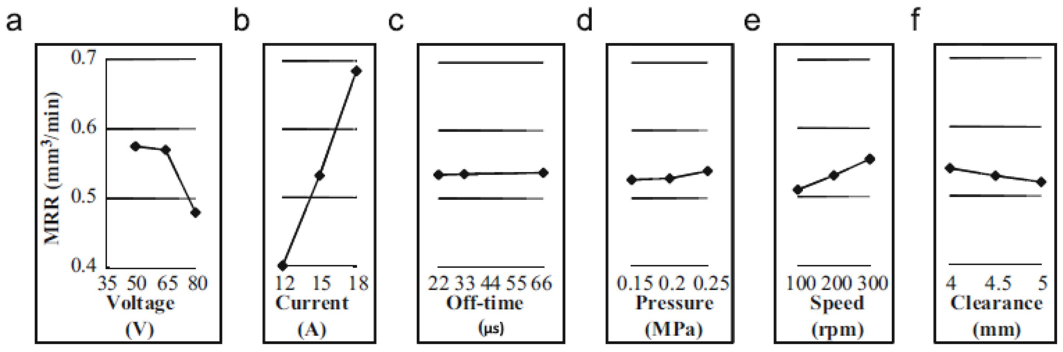
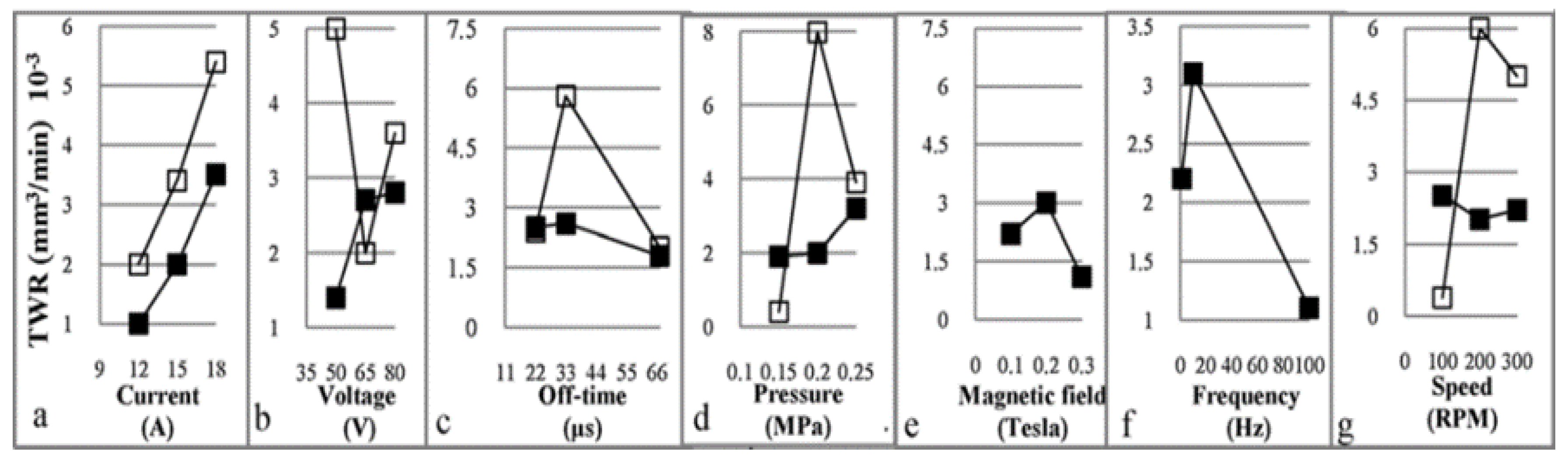
| 12 | [174] | Dry EDM | Voltage, current, pulse-off time, oxygen pressure, electrode tool speed and shielding clearance | MRR, TWR, oversize and SR | MRR was significantly affected by gap voltage, discharge current and electrode tool rotational speed. Optimal processing parameters to achieve maximum MRR and depth were (50 V, 18 A, 22 ms, 0.25 MPa, 300 rpm and 4.5 mm) and zero TWR was observed. The crater radius and MRR in the dry EDM were more than those in the liquid dielectric EDM at low input energies. At higher discharge energies, larger crater radius and MRR were observed. |
| 13 | [204] | Micro-WEDM | Open voltage, discharge capacitor, charge resistance, feeding speed, reference voltage and wire tension | Kerf width | The open voltage was the main factor influencing the kerf width in the micro-WEDM. |
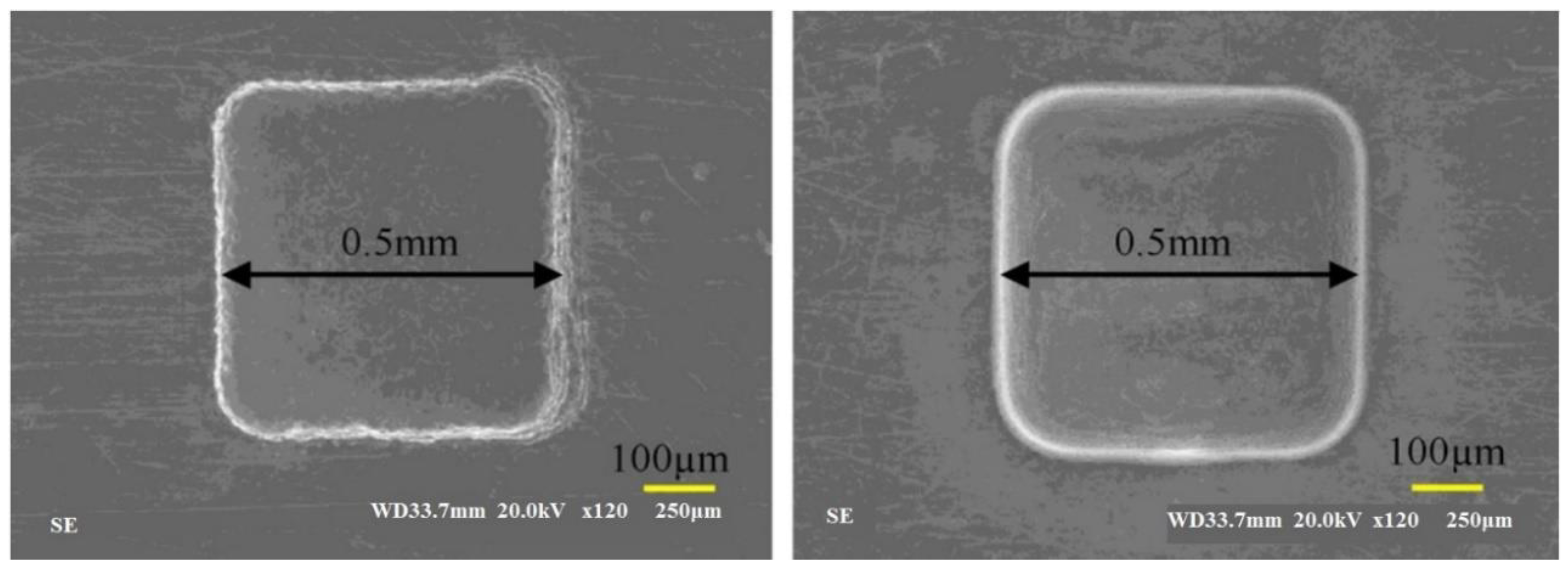
| 14 | [182] | Micro-EDM | Orbit radius and capacitance | Machining time and MRR | The orbiting technique provided more uniform geometries of machined holes and greatly improved the bottom quality for blind holes. It reduced tooling needs and electrode tool wear but increased machining times. |
| 15 | [88] | EDM | Dielectric fluid | SR | Discharge frequency and pulse number ↓with ↑ in the concentration of starch and alumina. More starch particles and alumina powder reduced the discharge efficiency. Using electro-rheological (ER) fluid and starch particles without abrasive Al2O3 improved the SR. Adding the abrasive to the ER fluid improved the SR. The roughness of SR (= 0.3 µm) obtained with ER fluid improved to 0.06 µm with the addition alumina powder. |
| 16 | [156] | EDM | Pulse duration, workpiece rotating speed, electrode tool polarity and current | MRR and relative EWR | The removal rate of material was proportional to the current. MRR for SUS 304 ↑ as pulse duration ↑ and the EWR started to ↓ when pulse duration reached 80 µs. The MRR of SUS 304 was larger for cathode discharge than anode discharge. The largest MRR and the lowest EWR appeared when the workpiece was rotated at 8 rpm. The developed triple-electrode machining system had a great effect in increasing the MRR and decreasing the ERR compared to the single-electrode system. |
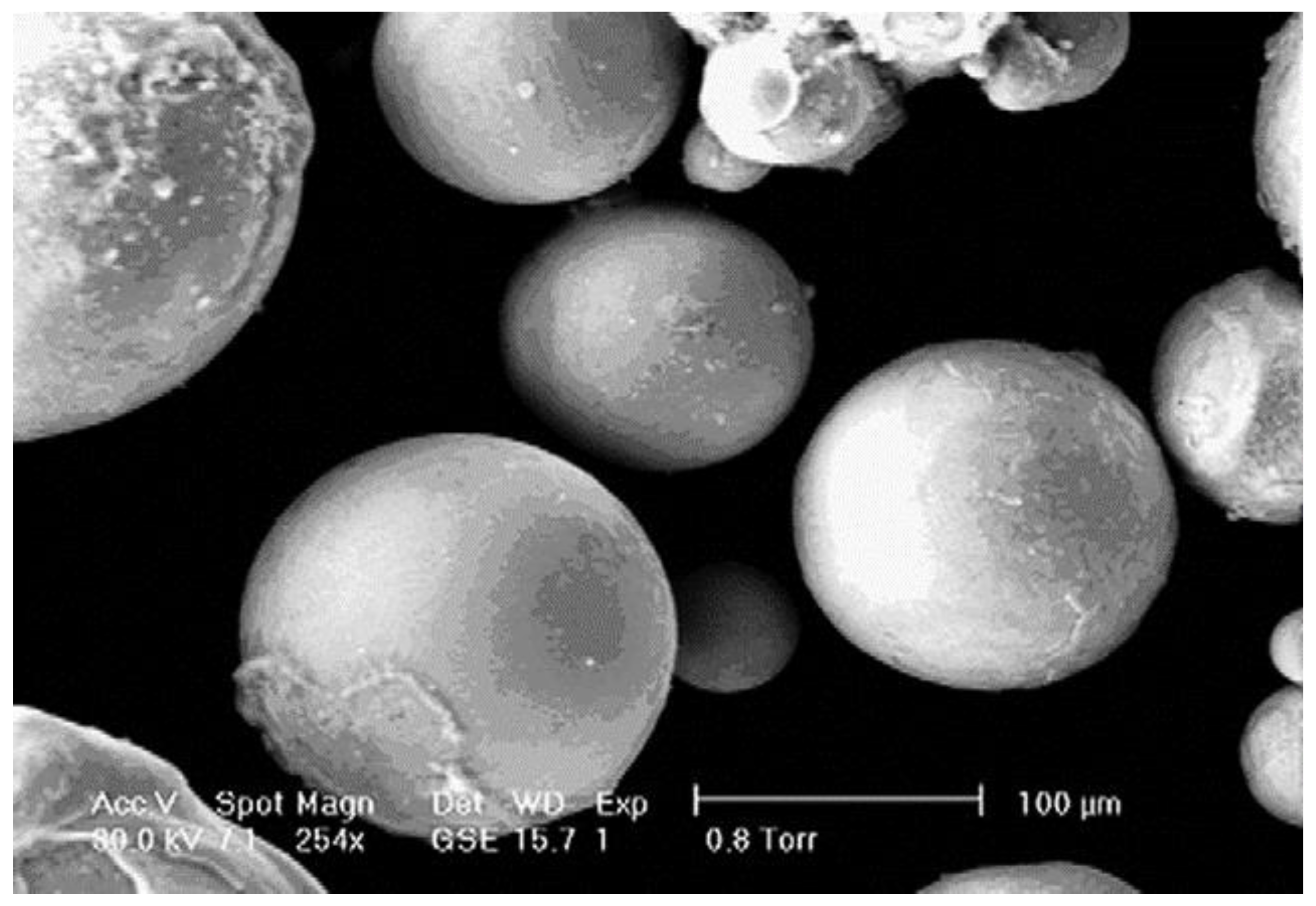
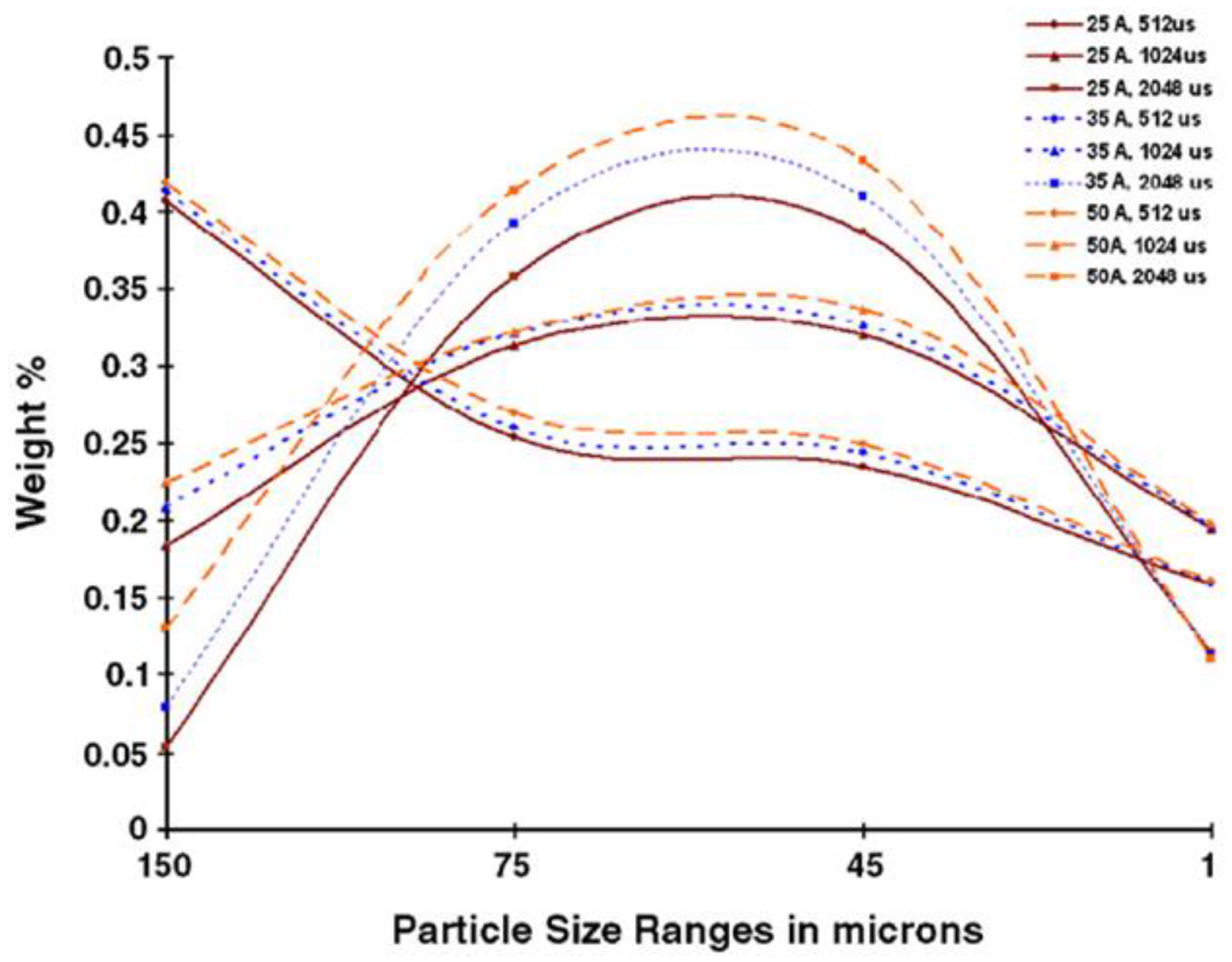
| 17 | [170] | EDM | Arc intensity, dielectric medium and pulse width | Particle size | The yield of larger particles ↑ with ↑ arc current. The size distribution width ↑ as pulse width ↑. The yield of particles of all sizes was higher in kerosene than in water. The required range of particles sizes could be achieved with higher available current intensities and narrow pulse widths. |
| 18 | [158] | Micro EDM | Voltage, current and on/off time of the pulse | MRR and TWR | The main parameters that affected the MRR are voltage, current and pulse-on/off time. The voltage and current were proportional to the MRR. But only current was proportional to the TWR. Gap ↑ as voltage and current ↑ and it ↓ as length of pulse-on time ↑. Shorter pulse-on duration achieved accurate machining with a higher removal rate and a lower tool wear rate. |
| 19 | [183] | EDM | Current density | SR and TWR | Considering the temperature dependence of the conductivity was important in achieving accurate numerical results to provide better correlation with the experimental observations. |
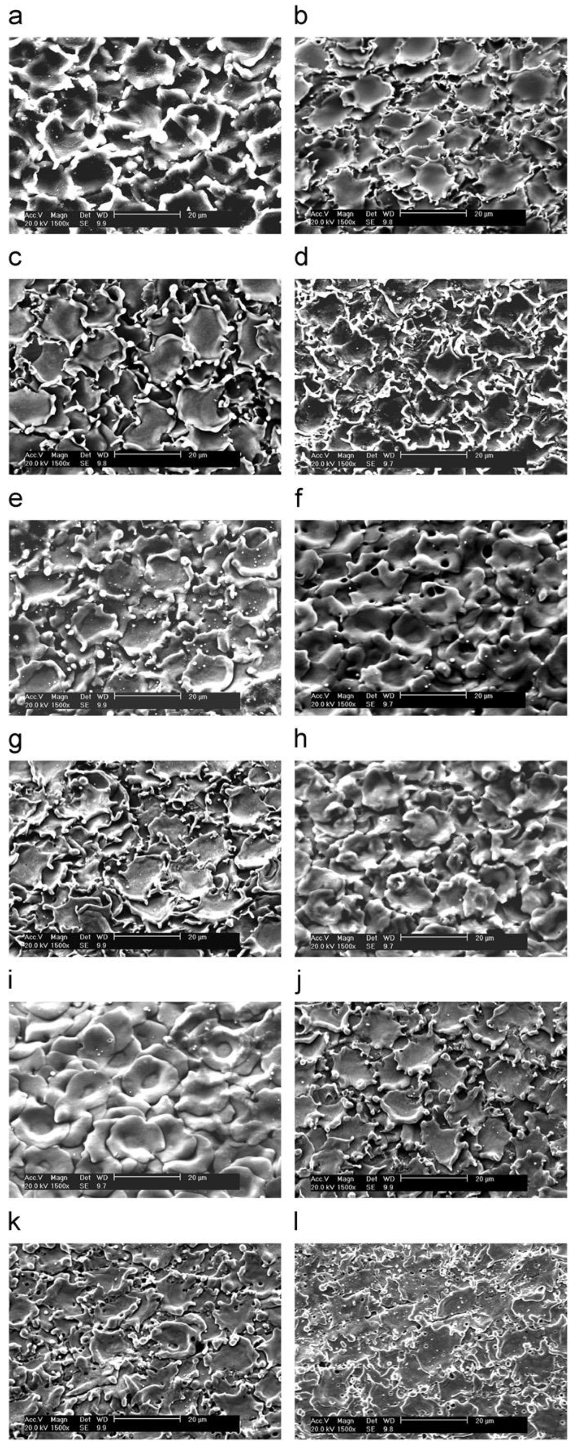
| 20 | [108] | WEDM | Current, discharge duration, time between pulses, feeding speed, wire tension and flushing pressure | Surface morphologies | The significance of surface alloying was proportional to the passive current density. The presence of the secondary anodic peak was attributed to the dissolution of copper, the main element of the wire–electrode material, from the alloyed surface. |
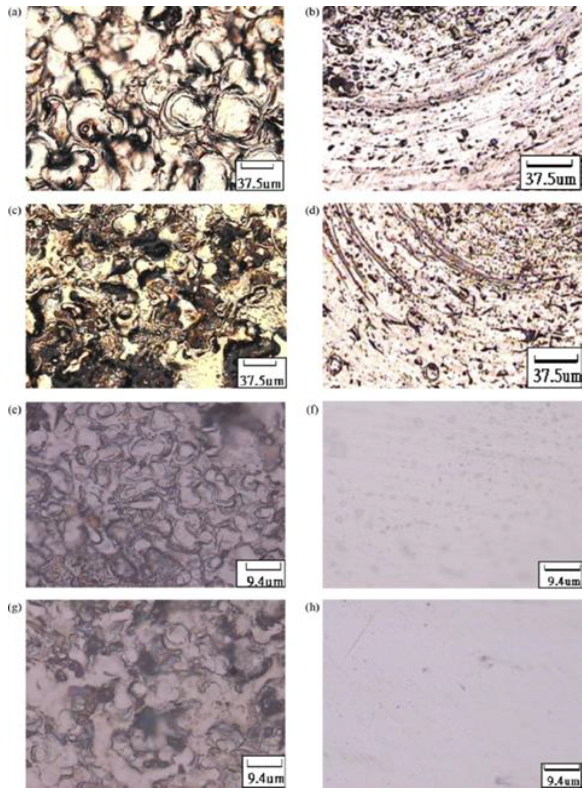
| 21 | [191] | WEDM | Discharge duration, time between pulses, feeding speed and wire tension | Micro- structure of the finished surface | A HAZ of about 1.5 µm thick was found in the finished surfaces with the negatively polarized wire electrode. Fine equiaxed martensitic grains of about 200 nm were composed the HAZ. No HAZ was found with use of the positively polarized wire electrode. |
| 22 | [41] | Micro-EDM | Ultrasonic driving voltage, workpiece materials, machining method and workpiece thickness | MRR | The workpiece vibration caused by the ultrasonic action had a significant influence on the performance of the micro-EDM process. For workpiece of 0.5 mm thickness, the efficiency of the micro-EDM with ultrasonic action was eight times greater than the micro-EDM without ultrasonic activation. |
| 23 | [192] | Wire EDM | Pulse width, time between pulses, wire tension and feed speed | SR | The artificial neural networks model was better than the response surface methodology in predicting the SR and the cutting speed. |
| 24 | [212] | Micro EDM | Applied energy, HAZ and foil susceptibility to corrosion | Nozzle stability | As the energy input ↓ the quality of nozzles produced by MEDM ↑. Nozzle performance ↓ as carbon content and MEDM input energy ↑. |
| 25 | [214] | Wire-EDM | Pulse-on time, pulse- off time, current, no-load voltage, servo reference voltage, capacitor setting and servo speed setting | SR and machining speed | The method developed can improve the efficiency and effectiveness of the process whereby the optimal parameters are determined. |
| 26 | [164] | EDM | Pulse current, pulse on time and pulse off time | SR | The pulse current and pulse on time are the most significant machining parameters on the obtained surface roughness values. |
| 27 | [163] | EDM | Pulse-on time, peak current, gap voltage and tool thickness | MRR and TWR | The pulse on time is the most influencing factor that affects MRR and TWR. Voltage and tool thickness also identified as significant parameters, however, its effect is less than pulse-on time. |
| 28 | [208] | Wire-EDM | Pulse on time, pulse off time and wire tension | cylindricity error | Wire tension has highest contribution on cylindricity error which is lowest at high value wire tension. Pulse on time has minor contribution on the cylindricity error and it increases with the increase of pulse on time. Pulse of time does not have any influence on the cylindricity error. The circularity error was lowest at medium pulse off time and medium wire tension; and those two parameters have almost similar and highest contributions |
| 29 | [184] | EDM | Gap voltage and pulse on-time | SR | At low level of operating parameters, the surface irregularities such as micro-globules and micro-cracks by copper electrode tool is lesser than the surface irregularities by other electrode tool materials. At high levels of operating parameters, a denser distribution of surface irregularities due to high electrical discharge efficiency was observed. |
| 30 | [185] | EDM | Peak current, servo voltage, pulse on time, pulse off time and servo speed | TWR | Peak current is the most significant parameter to the TWR value |
| 31 | [172] | Micro EDM | Polarity | TWR | The direct polarity has significant in reducing the tool wear over the reverse polarity for the three electrode tools and the material removal rate is maximized with the direct polarity |
| 32 | [199,200] | EDM | Peak current, pulse on time, pulse off time and tool lift time | MRR and SR | Peak current, pulse on time and tool lift time have significantly affected the material removal rate and surface roughness. |
| 33 | [180] | EDM | Discharge current, pulse on time and duty cycle | MRR and SR | The proposed method maximize MRR and minimize SR |
| 34 | [181] | Wire EDM | Pulse on time, pulse off time, current and voltage | MRR | Pulse on time and current are greatly influence on the material removal rate. |
| 35 | [162] | EDM | Peak current, pulse duration and electrode diameter | SR | EDM parameters have a significant influence on machining characteristic such that surface roughness |
| 36 | [209] | Wire EDM | Peak current, pulse on time and wire feed | MMR and SR | The pulse on time is most significant parameter with percentage contribution about 87.29% |
| 37 | [165] | EDM | Current, pulse on time, voltage and inter electrode gap | MRR, TWR and SR |
| No | Authors (Ref) | Process | Workpiece Material | Objective Function |
|---|---|---|---|---|
| 1 | [197] | Micro-wire EDM | 1Cr18Ni9Ti | Predicting the cone angle and its effect on the accuracy of the 3D micro-cavity |
| 2 | [48] | Dry EDM | AISI 304 | Influence of the working parameters on the performance parameters |
| 3 | [193] | Wire EDM | Stavax (modified AISI 420) | Influence of the working parameters on the performance parameters |
| 4 | [188] | Die-sinking EDM | AISI 202 | Surface quality and performance measures in EDM of stainless steel |
| 5 | [159] | Die-sinking EDM | Stainless steel #304 | Proposing a strip electrode and guide system to overcome the electrode tool wear problem during the EDM process |
| 6 | [166] | Die-sinking EDM | Stainless steel #304 | Proposing strip-EDM in the EDM-turning process to overcome the tool electrode tool wear problem. The paper also studies the influence of the working parameters on the performance parameters |
| 7 | [177] | Dry EDM | Stainless steel #304 | Influence of the working parameters on the performance parameters |
| 8 | [205] | Micro-EDM | Stainless steel plate | Studied the surface quality of micro-holes |
| 9 | [167] | Micro-EDM | Stainless steel #304 | Layer machining |
| 10 | [175] | Dry EDM | Stainless steel #304 | Influence of the working parameters on the performance parameters |
| 11 | [171] | Micro-ECM | Stainless steel #304 | Investigated micro-EDM and micro-ECM for combined milling of a 3D micro-structure |
| 12 | [202] | Die-sinking EDM | Stainless steel | Developed a pulse generator capable of shutting off harmful pulses |
| 13 | [56] | Die-sinking EDM | AISI 202 | Influence of the working parameters on the performance parameters |
| 14 | [176] | Dry EDM | Stainless steel #304 | Influence of the working parameters on the performance parameters |
| 15 | [160] | Die-sinking EDM | Stainless steel #304 | Influence of the working parameters on the performance parameters |
| 16 | [157] | Die-sinking EDM | Stainless steel #304 | Influence of the working parameters on the performance parameters |
| 17 | [187] | Micro-EDM | SUS316L | This study explored the feasibility of using a die-sinking micro-electrical discharge machining technique to fabricate miniature metallic bipolar plates |
| 18 | [136] | Dry EDM | Stainless steel | Presented an investigation of the hybrid dry EDM process performed in a pulsating magnetic field for improving process performance |
| 19 | [194] | Micro-EDM | Ferralium 255 SD 50 | Combined single electrical discharge electro-thermal model with online monitoring of EDM discharge gap to estimate the material removal volume in real time |
| 20 | [174] | Dry EDM | Stainless steel #304 | Influence of the working parameters on the performance parameters |
| 21 | [195] | Die-sinking EDM | 15–5PH | Studied the role of EDM on fatigue performance |
| 22 | [204] | Micro-EDM | Stainless steel | Concentrated on kerf analysis in micro-WEDM |
| 23 | [221] | Micro-EDM | Stainless steel | Combined ultrasonic vibration with planetary movement of an electrode tool to drill micro holes |
| 24 | [182] | Micro-EDM | Stainless steel #316 | Reported on electrode tool orbiting of micro-holes |
| 25 | [203] | Die-sinking EDM | Stainless steel | Presented a fundamental study of the total energy of discharge pulses required to machine different workpiece materials |
| 26 | [88] | Die-sinking EDM | Stainless steel #304 | Proposed a method of EDM that used ER fluid instead of water or oil. The paper also studied the influence of the working parameters on the performance parameters |
| 27 | [156] | Die-sinking EDM | Stainless steel #304 | Designed a new mechanism for pipe cutting combined with EDM. Influence of the working parameters on performance parameters. The influence of working parameters on performance parameters was also studied |
| 28 | [170] | Die-sinking EDM | Stainless steel #304 | Influence of the working parameters on the performance parameters |
| 29 | [158] | Micro-EDM | Stainless steel #304 | Influence of the working parameters on the performance parameters |
| 30 | [183] | Die-sinking EDM | AISI316L | Presents numerical results concerning the temperature distribution caused by the EDM process |
| 31 | [108] | Wire EDM | Martensitic stainless steel | Studied the surface alloying behaviour of martensitic stainless steel |
| 32 | [191] | Wire EDM | AISI 440A | Studied a microstructure analysis of the martensitic stainless steel |
| 33 | [41] | Micro-EDM | Stainless steel | Presented a combination method of ultrasonic and electrical-discharge machining |
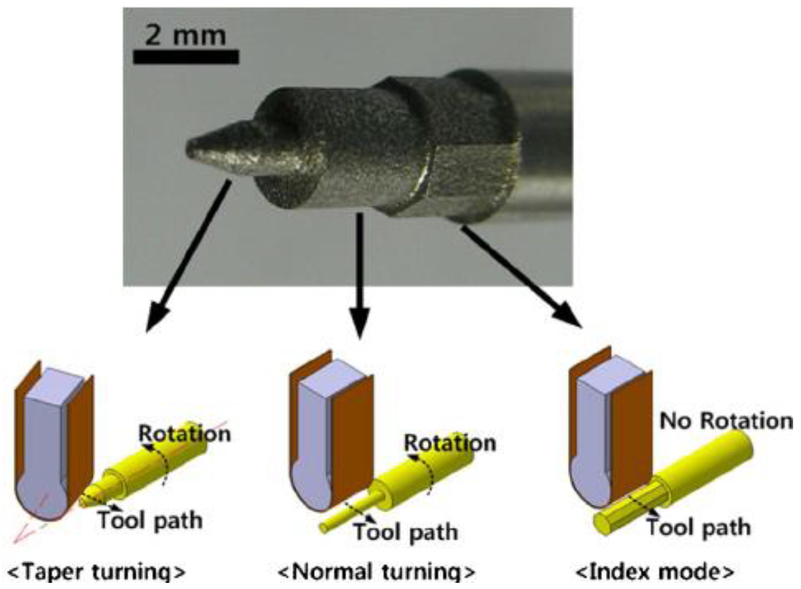
| 34 | [168] | Micro-EDM | Stainless steel #304 | Proposed a new type of micro-EDM machine, where the machine operated similarly to a turning lathe |
| 35 | [179] | Micro EDM | AISI 304L | Presented a new approach based on the principle of planetary movement of an electrode tool |
| 36 | [169] | Micro-EDM | Stainless steel #304 | Proposed an approach to integrate CAD/CAM systems with micro-EDM |
| 37 | [213] | Die-sinking EDM | Stainless steel | Studied the influence of the working parameters on the performance parameters |
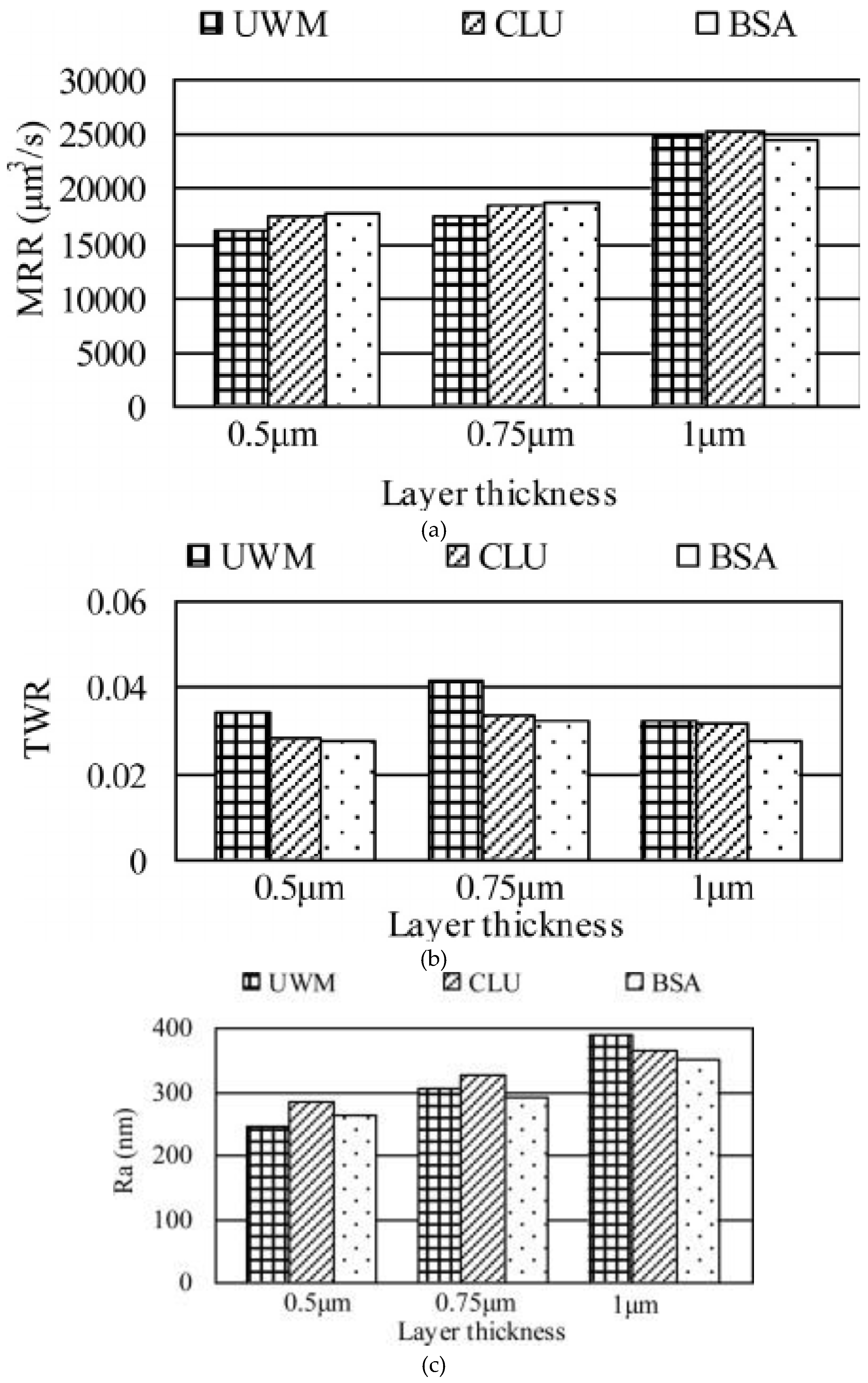
| 38 | [219] | Micro-EDM | Stainless steel | Proposed uniform wear method for 3D micro-EDM with round or rectangular section electrode tools developed for micro-moulds |
| 39 | [192] | Wire EDM | AISI 420 | Developed modelling techniques for a wire EDM process |
| 40 | [212] | Micro EDM | Stainless steel | Studied the effects of MEDM on the hole properties |
| 41 | [214] | Wire EDM | Stainless steel #304 | Utilized a feed-forward neural network to correlate working parameters on performance parameters |
| 42 | [164] | Die-sinking EDM | Stainless steel #304 | Studied the effect of the pulse current, pulse on time and pulse off time on the surface roughness |
| 43 | [163] | Die-sinking EDM | Stainless steel #304 | Investigated the effect of machining parameters and tool thickness on the MRR and TWR |
| 44 | [208] | Wire EDM | 2205 duplex stainless steel | Studied the types of errors generated on the feature machined |
| 45 | [184] | Die-sinking EDM | Stainless steel 316L | Studied the effect of operating parameters on the surface roughness |
| 46 | [161] | Die-sinking EDM | Stainless steel #304 | Studied the effect of deep cryogenically treated post tempered electrode tools |
| 47 | [185] | Die-sinking EDM | Stainless steel 316L | Investigated the influence of EDM parameters on electrode tools wear rate |
| 48 | [172] | Micro EDM | Stainless steel #304 | Investigated the effect of polarity in tool wear and MRR |
| 49 | [199,200] | Die-sinking EDM | 17-4 Precipitation Hardening Stainless Steel | Obtained the optimal process parameters of EDM |
| 50 | [173] | Micro EDM | Stainless steel #304 | Developed a micro punching system with a micro electrical discharge machining |
| 51 | [201] | Die-sinking EDM | SUS430 | Investigated the thermal strain caused by EDM |
| 52 | [180] | Die-sinking EDM | AISI 316 Stainless steel | Optimized the machining parameters |
| 53 | [181] | Wire EDM | Stainless steel 316 | Optimized of wire EDM processes parameters |
| 54 | [162] | Die-sinking EDM | Stainless steel #304 | Characterized the electric discharge machining |
| 55 | [209] | Wire EDM | Stainless steel 410 | Studied the effect of process parameters on material removal rate and surface roughness |
| 56 | [189] | Die-sinking EDM | AISI 202 | Studied the influence of the pulse generator systems on white layer formation |
| 57 | [165] | Die-sinking EDM | Stainless steel #304 | Studied the effect of machining parameters on the material removal rate, tool wear rate and surface roughness |
| 58 | [186] | Die-sinking EDM | Stainless steel 316L | Investigate the influence of dielectric on material removal rate, surface roughness and whit layer thickness |
© 2019 by the authors. Licensee MDPI, Basel, Switzerland. This article is an open access article distributed under the terms and conditions of the Creative Commons Attribution (CC BY) license (http://creativecommons.org/licenses/by/4.0/).
Share and Cite
Abu Qudeiri, J.E.; Saleh, A.; Ziout, A.; Mourad, A.-H.I.; Abidi, M.H.; Elkaseer, A. Advanced Electric Discharge Machining of Stainless Steels: Assessment of the State of the Art, Gaps and Future Prospect. Materials 2019, 12, 907. https://doi.org/10.3390/ma12060907
Abu Qudeiri JE, Saleh A, Ziout A, Mourad A-HI, Abidi MH, Elkaseer A. Advanced Electric Discharge Machining of Stainless Steels: Assessment of the State of the Art, Gaps and Future Prospect. Materials. 2019; 12(6):907. https://doi.org/10.3390/ma12060907
Chicago/Turabian StyleAbu Qudeiri, Jaber E., Ahmad Saleh, Aiman Ziout, Abdel-Hamid I. Mourad, Mustufa Haider Abidi, and Ahmed Elkaseer. 2019. "Advanced Electric Discharge Machining of Stainless Steels: Assessment of the State of the Art, Gaps and Future Prospect" Materials 12, no. 6: 907. https://doi.org/10.3390/ma12060907