Statistical Analysis and Preliminary Study on the Mix Proportion Design of Self-Compacting Steel Fiber Reinforced Concrete


1
International Joint Research Lab for Eco-building Materials and Engineering of Henan, North China University of Water Resources and Electric Power, Zhengzhou 450045, China
2
School of Engineering, RMIT University, Melbourne, VIC 3001, Australia
*
Authors to whom correspondence should be addressed.
Materials 2019, 12(4), 637; https://doi.org/10.3390/ma12040637
Submission received: 21 January 2019
/
Revised: 12 February 2019
/
Accepted: 18 February 2019
/
Published: 20 February 2019
Abstract
:With the sustainable development of green construction materials in civil engineering, self-compacting steel fiber reinforced concrete (SC-SFRC) has attracted widespread attention due to its superior self-compacting performance and excellent hardened properties. In this paper, 301 groups of test data from published literatures were collected to quantify the characteristics of the mix proportion of SC-SFRC. The type, aspect ratio and volume fraction of steel fiber commonly used in SC-SFRC are discussed and the effects of steel fiber on the workability and mechanical properties of SC-SFRC are statistically studied. The relationship of cubic compressive strength and water-to-binder ratio and that of the splitting tensile strengths between SC-SFRC and referenced self-compacting concrete (SCC) are also evaluated. Based on these analyses, the reasonable ranges of material components in the mix proportion design of SC-SFRC are determined. The results showed that with several adjusted parameters, the calculation model of the water-to-binder ratio for the mix proportion design of ordinary concrete is suitable for SC-SFRC. The calculation model of tensile strength is suggested for SC-SFRC with various types of steel fiber.
1. Introduction
Self-compacting steel fiber reinforced concrete (SC-SFRC) is a type of high performance concrete with the benefits of self-compacting performance at the fresh stage and superior mechanical properties at the hardened stage. The composition, production and mechanism of SC-SFRC are more complicated than those of self-compacting concrete (SCC). Due to the large density, elongated shape and large surface area of steel fiber [1], the direct addition of steel fibers in SCC would impair the self-compacting performance and disturb the solid skeleton of fresh concrete [2,3,4]. Nowadays, studies showed that a limited volume fraction of steel fiber could be used in SC-SFRC in order to ensure higher workability and better mechanical performance. Due to the packing effect of the fiber-aggregate solid skeleton, the self-compacting performance could not be achieved once the volume fraction of steel fiber in concrete exceeds the limited value even if the concrete mixture is a homogeneous and stable suspension [5]. The limitation (usually less than 2%) is mainly affected by the characteristics of raw materials [2,6,7] and mix proportion [8,9,10,11,12]. The characteristics of the raw materials include the maximum particle size and surface morphology of coarse aggregate, volume fraction, aspect ratio and geometry of steel fiber, binder paste content and sand ratio. The volume fraction of steel fiber used in SC-SFRC increased in proportion to the sand ratio [12]. A higher volume fraction of steel fiber for SC-SFRC could be used by altering the compositions of concrete mixture and adjusting the characteristics of steel fibers.
At present, various mix design methods for SC-SFRC have been reported. The binary mixture method [4,9,13,14,15,16,17,18,19,20,21] is one of the most commonly used methods, in which steel fibers are directly added to SCC. The workability of fresh SC-SFRC is tested to evaluate its satisfaction in terms of the required self-compacting performance. If self-compacting could not be achieved, the material compositions were subsequently adjusted without affecting the water-to-binder ratio (w/b). The adjustment measures include adding chemical admixture [13,18,19,20,21] and taking the volume of steel fiber into the consideration of an aggregate [9,15,16] or coarse aggregate [4]. The method has several disadvantages, such as project targeting, particularized condition and poor adoptability. The actual applications relied on the experience of engineering technicians.
Another mix design method is the modified Densified Mixture Design Algorithm (DMDA) [22,23], which is based on the required durability. The principle is low water content and low cement content to enhance the durability. The detailed measures included three steps. Firstly, we maximized the pile-up density of aggregates and fly ash using the loose packing test to optimize the content of fly ash and aggregates. After this, we added steel fibers as part of the solid volume and calculated the lowest void fraction of solid skeleton. Finally, we calculated the total paste volume with consideration of the thickness of lubricating paste. It can be seen that only the influence of volume of steel fiber is taken into account in this method.
Grünewald [2] proposed a performance-based mix design method for SC-SFRC. This method uses the Compressive Packing Model (CPM) [3] and assumes that the steel fiber is the equivalent packing diameter [24]. The virtual packing density of the steel fibers was calculated from the experimental packing density under the consideration of the wall-effect (experimental results) and the applied compaction process (the compaction index K = 3.6, which is experimentally determined for the deposition method). Ferrara [25] presented a “rheology of paste model” mix design method for SC-SFRC. The method chose to include steel fibers in the particle size distribution of the solid skeleton by creating the concept of an equivalent diameter of the same specific surface. The parameters of these methods have complex calculation processes and require high theoretical knowledge for engineering technicians.
Eduardo [26] and Barros [7] produced SC-SFRC by optimizing the composition of binder materials and that of aggregates, respectively. The optimization of binder materials is based on the requirements of both workability and compressive strength. The optimization of the particle size distribution of aggregates is experimentally determined by the packing test of steel fiber–aggregates solid skeleton. In addition, the volume fraction of steel fiber is included according to the engineering requirement. The minimum binder paste in SC-SFRC is chosen according to the self-compacting performance. This method is project targeted and needed a large amount of experimental data to evaluate the influence of steel fiber on the solid skeleton.
Besides, Sahmaran [27] attempted to produce SC-SFRC by simply increasing water content with constant contents of binder and chemical admixtures. Cai [28] produced SC-SFRC by increasing contents of water and binder with constant w/b. Anastasiou [29] produced SC-SFRC by increasing the amount of ladle furnace slag used with constant w/b. Li [12] reported that the optimal sand ratio of SC-SFRC should consider the volume fraction of steel fibers.
The solid skeleton of aggregates or steel fiber–aggregates and its balance with the binder content are considered in the above-described mix design methods. The addition method of steel fibers is the major difference among them. The limit of the type and volume fraction of steel fibers in these methods are not clear. Thus, more statistical analysis, quantity trails of experiments and a simplified calculation process are needed for determining the mix proportion design of SC-SFRC.
In this paper, the experimental database of SC-SFRC is built. Combined with the previous study of the numerical analysis of mix proportion for SCC [30], the differences of compositions between the SC-SFRC and SCC are systemically discussed. Moreover, the type, aspect ratio and volume fraction of steel fibers commonly used in SC-SFRC are discussed. The effects of the fiber factor on the workability and mechanical properties are statistically studied. The relationship of w/b and cubic compressive strength of SC-SFRC as well as splitting tensile strengths between SC-SFRC and referenced SCC are studied.
2. Statistical Analysis for Mix Proportion of SC-SFRC
2.1. Experimental Database
In this paper, 301 groups of test data for SC-SFRC from previous literatures [2,9,10,12,13,14,15,16,17,18,19,22,23,26,27,28,29,31,32,33,34,35,36,37,38,39,40,41,42,43,44,45,46,47,48,49,50,51,52,53,54,55,56,57,58,59,60,61] were collected to build the database. The range of results used for the experimental database are listed in Table 1. The mineral admixtures of SC-SFRC in the experimental database included parts of fly ash, slag powder, silica fume and stone powder. It should be noted that some values of the cylinder compressive strength used in the experimental database were converted into the cubic compressive strength (fcu). The conversion factors are followed by the reference [62]. The detailed information of experimental database for SC-SFRC is presented in Appendix A.
2.2. Aggregates
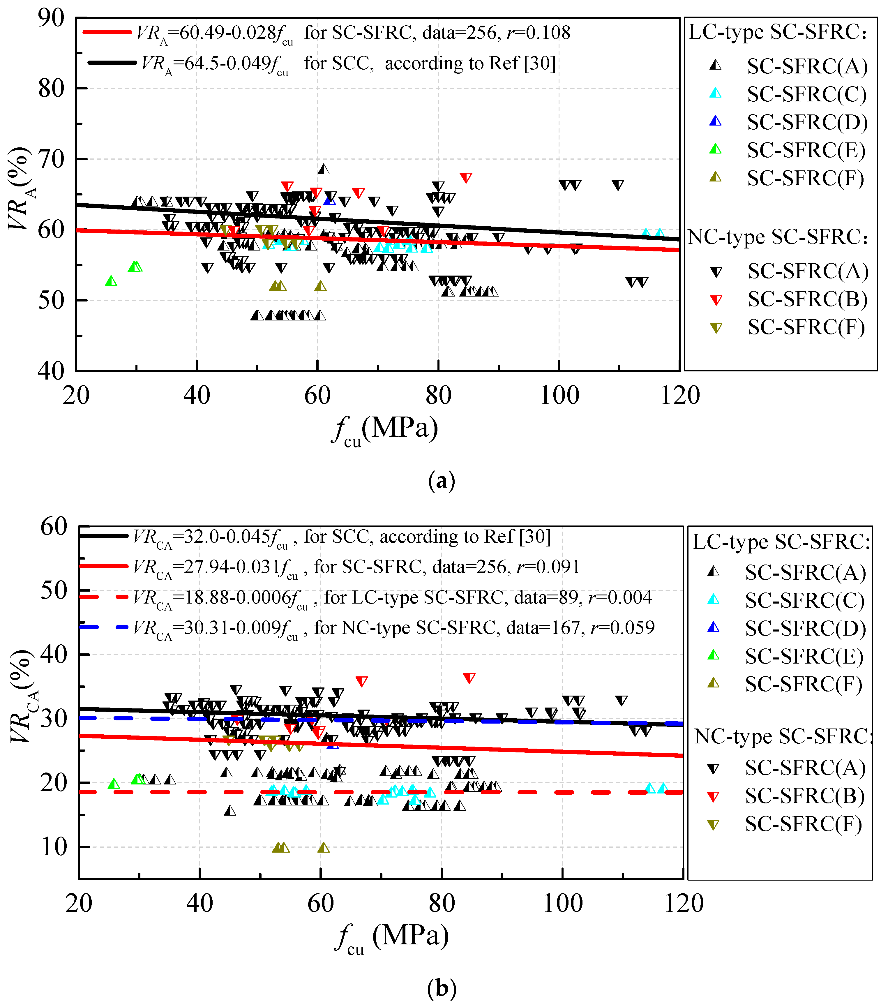
Figure 1 displays the variations of the volume content of aggregates, coarse aggregate and fine aggregate (VRA, VRCA and VRFA) along with the cubic compressive strength fcu for SC-SFRC. SC-SFRCs (A)–(G) form the test data of SC-SFRC with a binary mixture design method, modified DMDA method, modified CPM method, method based on the packing test of steel fiber–aggregates, method of changing water content, method of increasing water and binder contents with w/b constant and method of increasing binder content, respectively. The volume content of their raw materials are distinguished using points of different color. VRa, VRCA and VRFA changed by 45–70%, 10–35% and 25–45% for SC-SFRC, respectively. Both VRA and VRCA show a small decrease with increased cubic compressive strength. VRFA shows little regularity with increased cubic compressive strength. Linear fitting was used to obtain the trendline. Trendlines of VRA, VRCA and VRFA along with fcu for SCC [30] are drawn as black lines where r is the correlation coefficient of the regression equation. It can be seen that VRA and VRCA of SC-SFRC are about 1.49–3.59% and 4.18–4.78% lower than those of SCC, respectively. Compared with SCC, one feature of the mix proportion for SC-SFRC is the lower VRA and VRCA values.
In term of self-compacting performance, a smaller content of coarse aggregate leads to less blocking effect and high flowability of fresh concrete. A suitable volume content of fine aggregate and a certain range of sand ratio would increase the segregation resistance of fresh concrete. However, a higher volume content of coarse aggregate would be beneficial in restricting the shrinkage deformation of hardened concrete, which is consistent with the requirements of the concrete structure performance. Thus, considering the different volume contents of coarse aggregate and fine aggregate, the mix proportion of SC-SFRC is classified into two types, which was named as NC-type SC-SFRC (legends of chamfering triangle in Figure 1 and Figure 2) and LC-type SC-SFRC (legends of triangle in Figure 1 and Figure 2), respectively. NC-type SC-SFRC has a volume content of coarse aggregate that is more than 600 kg/m3 and volume content of fine aggregate that is less than 1000 kg/m3. LC-type SC-SFRC has coarse aggregate content that is less than 600 kg/m3 and fine aggregate content that is more than 1000 kg/m3. LC-type SC-SFRC focuses more on the performance of fresh concrete, while NC-type SC-SFRC focuses on both the workability and volume deformation of hardened concrete. Similar VRA values were observed in NC-type and LC-type SC-SFRC. LC-type SC-SFRC has a VRCA and VRFA that was lower by 10.75–11.59% and higher by 5.64–7.34%, respectively, than NC-type SC-SFRC.
VRA, VRCA and VRFA of SC-SFRC with different mix design methods also showed some differences. SC-SFRC (C), SC-SFRC (D), SC-SFRC (E) and part of SC-SFRC (A) and SC-SFRC (F) can be categorized to LC-type SC-SFRC. In contrast, SC-SFRC (B) and part of SC-SFRC (A) and SC-SFRC (F) can be categorized to NC-type SC-SFRC.
Figure 2 shows the variation of sand ratios according to mass βs along with the cubic compressive strength. βs changed by 40–80% for SC-SFRC, which is about 3.0–4.1% higher than that of SCC. Moreover, more than 80% of the sand ratios of SC-SFRC were 47–69%. βs of LC-type SC-SFRC was higher by 15.9–16.2% than that of NC-type SC-SFRC.
Figure 3 shows the probability distributions of the maximum particle size (MA) of coarse aggregates for SC-SFRC and SCC. The test data of SC-SFRC with MA ≤ 10 mm, 10 mm < MA ≤ 16 mm, 16 mm < MA ≤ 20 mm and 20 mm < MA ≤ 25 mm are 28.4%, 49.6%, 21.0% and 1.0%, respectively. The test data of SCC [30] with MA ≤ 10 mm, 10 mm < MA ≤ 16 mm, 16 mm < MA ≤ 20 mm and 20 mm < MA ≤ 25 mm are 18.5%, 42.3%, 21.5% and 16.2%, respectively. Thus, one feature of SC-SFRC is the smaller MA of coarse aggregates compared to SCC.
2.3. Binder and Binder Paste
Figure 4 exhibits the variations of volume contents of the binder and binder paste (VRb, VRBP) along with the cubic compressive strength fcu. Similar to Figure 1 and Figure 2, the legends of the chamfering triangle are NC-type SC-SFRC and the legends of triangle are LC-type SC-SFRC. In this paper, the binder material is the sum of cement and mineral admixtures while VRBP is the sum of water and binder materials by volume. The influence of hydration reaction on the volume change of binder paste is ignored. VRb and VRBP changed by 12–30% and 30–55% for SC-SFRC, respectively. Similar to SCC [30], VRb and VRBP of SC-SFRC increased in proportion to the cubic compressive strength. VRR and VRBP of SC-SFRC are higher by approximately 0.47–0.97% and 0.92–2.82% compared to that of SCC, respectively. Thus, one feature of the mix proportion for SC-SFRC is the higher VRBP.
As shown in the red box line of Figure 4, several test data have higher VRb and VRBP values [27,28,51]. All these test data belong to LC-type SC-SFRC. Moreover, the experimental study of Abrishambaf used abundant binder materials of 766 kg/m3 and a slightly low water content of 140 kg/m3 [41] with fcu = 63 MPa. The limestone filler was considered as one of the binder materials.
VRb and VRBP of SC-SFRC with different mix design methods also show some differences. Comparing with the trendlines of VRb and VRBP, SC-SFRC (C) and SC-SFRC (G) have similar VRb and VRBP, SC-SFRC (E) and part of SC-SFRC (F) have higher VRb and VRBP due to the same reason discussed in the above paragraph. In contrast, SC-SFRC (B) and SC-SFRC (D) have lower VRBP due to the lower water content.
2.4. Steel Fiber
It can be summarized from the experimental database that the hooked-end steel fiber is the most commonly used, which was involved in about 54% of SC-SFRC. This was followed by 23% of SC-SFRC containing crimped steel fibers. All of the other macro steel fibers of straight, milled cut, indentation, twisted and large-end account for about 20%. In contrast, micro steel fiber is only involved in about 3% of SC-SFRC.
The histograms of the probability distributions of length lf, aspect ratio lf/df and fiber factor λf = ρf·lf/df of steel fiber are drawn in Figure 5 where df is the equivalent diameter of the cross-section of steel fiber and ρf is the volume fraction of steel fiber in concrete. More than 75% of lf were less than 42.5 mm, more than 56% of fiber length lf ranged from 30 mm to 35 mm, more than 58% of aspect ratio lf/df ranged from 50 to 70 and more than 80% of the fiber factor λf were less than 0.55.
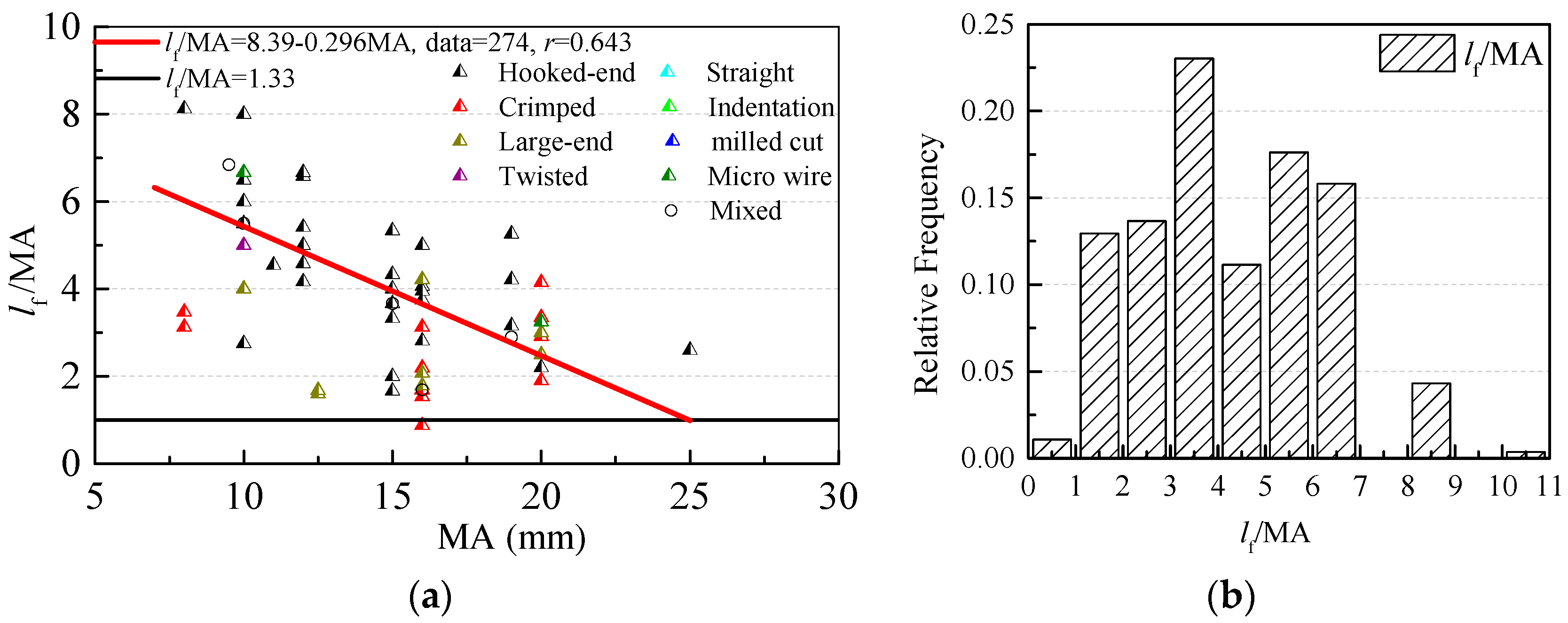
Figure 6 shows the relationship between fiber length lf and the maximum particle size of aggregate MA. To ensure an efficient reinforced effect of steel fibers, lf/MA should be larger than 1.33 in vibrated-compacting SFRC [63]. It can be seen that 99% of lf/MA are larger than 1.33 in SC-SFRC. lf/MA decreases with the increasing MA and 94% of lf/MA are between 1.5 and 6.5.
The influences of steel fiber on the fresh and hardened performances of SC-SFRC are shown in Figure 7. SF and SF0 are the slump flows of SC-SFRC and the referenced SCC, respectively. The ratio of the slump flow SF/SF0 forms a linear correlation with fiber factor λf, which decreases with an increase in λf. The type of steel fiber has no obvious influence on SF/SF0. Both the fiber factor and type have no obvious influence on the compressive strength. In this study, fcu and fcu0 are the cubic compressive strengths of SC-SFRC and the referenced SCC, respectively. We determined that 89.4% of the ratios of cubic compressive strength fcu/fcu0 ranged from 0.85 to 1.15.
3. Calculation Model of Water-to-Binder Ratio for SC-SFRC
The calculation model of w/b for the vibrated-compacting concrete in Chinese standard JGJ/T 55 [64] is:
where fcu,0 is the designed cubic compressive strength of concrete; αa and αb are coefficients mainly related to the type of coarse aggregate; and fb is the compressive strength of binder materials at 28 days (MPa), which can be predicted by Formula (2), when there is no measured value.
where fce is the compressive strength of cement at 28 days; γf is the influence coefficient of fly ash, which can be taken as values listed in Table 2 [65]; and γs is the influence coefficient of slag powder, which can be taken as the values specified in JGJ/T 55 [64]. With a similar influence, stone powder has the same influence coefficient with fly ash. Moreover, the influence coefficient of silica fume is taken as 1.0 conservatively in the following sections.
Besides, the calculation model of w/b for SCC in Chinese Standard JGJ/T 283 [66] is;
where β is the replacement ratio by the mass of mineral admixture in binder materials; and γ is the influence coefficient of mineral admixtures. These values are 0.4 and 0.9 for fly ash with β ≤ 0.3 and slag powder with β ≤ 0.4, respectively.
In fact, both Equations (1) and (3) have a form of reciprocal function and are identical in essence, which could be expressed in one form:
where κ is the influence coefficient of mineral admixture on the compressive strength of cement. Κ = γf·γs in JGJ/T 55, κ = 1 − β + β·γ in JGJ/T 283.
If fb = κfce, αab = −αaαb, Equation (4) can be transformed to Equation (5).
With b/w as the x-axis and fcu/fb as the y-axis, Figure 8 plots the test data and fitting result of SC-SFRC. The parameters αa = 0.319 with the standard deviation of 0.030 and αab = 0.291 with the standard deviation of 0.091 are obtained.
Considering the reliability of cubic compressive strength with a probability of 95% in the mix proportion design, αa = 0.270 and αab = 0.141 for SC-SFRC are obtained. Thus, αb = -αab/αa = −0.522.
The different coefficients reflect the different changes in w/b with cubic compressive strength fcu. With the same w/b, fcu of SCC is about 7–10 MPa lower than that of vibrated-compacting concrete [30]. For SC-SFRC, a w/b lower than that of vibrated-compacting concrete and higher than that of SCC is needed to achieve the same fcu. Thus, Equation (1) with αa = 0.270 and αb = −0.522 is advised for the mix proportion design of SC-SFRC.
4. Designed Tensile Strength of SC-SFRC
Steel fibers obviously strengthen the splitting tensile strength in SC-SFRC [20,60]. The calculation model of designed tensile strength fft for SC-SFRC is shown as Equation (6) [60].
where ft is the tensile strength of referenced SCC, which could be accurately estimated by using the EC-2 model [67,68,69]; αte is the coefficient related to the effective fiber distribution; and αtb is a coefficient that colligated the other factors, which influence the bridging effects of steel fibers in the splitting tensile test.
A total of 89 groups of splitting tensile test data in the experimental database were used to verify Equation (6). There were different advised values of αtbαte for different types of steel fibers according to Chinese standard JGT 472 [63]. The tested splitting tensile strength ft of SCC in the same strength grade was used to calculate the tensile strength fft,c of SC-SFRC. Apart from αtbαte = 0.5, the SC-SFRC with crimped steel fiber and cubic compressive strength of the referenced SCC ranged from 20 MPa to 60 MPa [60]. Moreover, a simple Formula (7) was used to calculate the tensile strength of SC-SFRC with hybrid steel fibers based on the previous study of concrete with hybrid steel fibers [70].
where κt is a coefficient of the hybrid effect for concrete with hybrid steel fibers. For concrete with hybrid steel fibers, κt > 1 means a positive hybrid effect between steel fibers while κt < 1 means a negative hybrid effect between steel fibers. For SC-SFRC mixed with hooked-end and straight steel fibers in this study, κt ≈ 1. It means that the hybrid effect did not exist in the hooked-end steel fiber and straight steel fiber with lengths that were smaller than 10 mm.
Figure 9 and Table 3 provide the detailed comparison of calculated tensile strength fft,c and tested tensile strength fft,t of SC-SFRC. The results show that Equation (6) with advised values of αtbαte is suitable for predicting the tensile strength of SC-SFRC with the steel fibers of hooked-end, crimped, milled, indentation and large-end. Equation (6) with advised values of αtbαte obviously underestimates the tensile strength of SC-SFRC with spiral steel fibers and overestimates that of SC-SFRC with straight steel fibers.
5. Conclusions
Based on the statistical analyses of test data for SC-SFRC, the following conclusions are drawn:
SC-SFRC has differences in the mix proportion compared with SCC. SC-SFRC usually has higher contents of binder paste and fine aggregate, higher sand ratio, lower content and smaller maximum particle size of coarse aggregates. Based on the content of coarse aggregates in the mix proportion, SC-SFRC could be divided into LC-type and NC-type. LC-type SC-SFRC has a significantly lower content of coarse aggregate and higher sand ratio compared with NC-type SC-SFRC. Most of the steel fibers used in SC-SFRC have lengths less than 37.5 mm, aspect ratios less than 70 and fiber factors no more than 0.45. The ratio of slump flows between SC-SFRC and the referenced SCC decreased with an increase in the fiber factor.
Based on the calculation model of water-to-binder ratio in Chinese standard JGJ/T 55, suitable coefficients are advised for the mix proportion design of SC-SFRC. The calculation model of the designed tensile strength with advised coefficients according to Chinese standard JGT 472 is suitable for SC-SFRC with steel fibers of hooked-end, milled, indentation and large-end. The calculation model of the designed tensile strength with coefficients proposed in the authors’ previous study is suitable for SC-SFRC with crimped steel fibers. More adjustments in the mix proportion design of SC-SFRC, such as determining the dosages of binder materials and water and optimizing sand ratios, need to be further studied.
Author Contributions
Methodology, X.D.; Investigation, M.Z. and X.D.; Data Curation, X.D. and S.Z; Writing—Original Draft Preparation, X.D.; Formula Analysis, Y.F.; Writing—Review & Editing, C.L.; Funding Acquisition, C.L.
Funding
This research was funded by [State Key Research and Development Plan, China] grant number [2017YFC0703904], [Innovative Sci-Tech Team of Eco-building Material and Structural Engineering of Henan Province, China] grant number [YKRZ-6-066] and [the Key Scientific and Technological Research Project of University in Henan, China] grant number [17A560025].
Conflicts of Interest
The authors declare no conflict of interest.
Appendix A

Table A1.
Ranges of main parameters of SC-SFRC.
| Ref. no | Cement Type | N | w/b | w/c | MA (mm) | βs (%) | Steel Fiber | fcu (MPa) | fft (MPa) | SF (mm) | |||
|---|---|---|---|---|---|---|---|---|---|---|---|---|---|
| Type | lf (mm) | lf/df | ρf (%) | ||||||||||
| [2] | CEM III 42.5N + CEM I 52.5R or/and CEM III 52.5A | 16 | 0.30 | 0.47 | 16 | 68 | Hooked-end | 60 | 80 | 0.77 | 54 | 6.3 | – |
| 0.30 | 0.47 | 16 | 68 | Hooked-end | 30 | 80 | 0.77 | 58 | 6.6 | – | |||
| 0.30 | 0.47 | 16 | 68 | Hooked-end | 40 | 65 | 1.28 | 52 | 6.6 | – | |||
| 0.30 | 0.47 | 16 | 68 | Hooked-end | 30 | 45 | 1.79 | 56 | 7.6 | – | |||
| 0.32 | 0.46 | 8 | 70 | Hooked-end | 30 | 80 | 0.51 | 70 | 7.6 | – | |||
| 0.32 | 0.46 | 8 | 70 | Hooked-end | 20 | 65 | 0.77 | 76 | 7.4 | – | |||
| 0.31 | 0.44 | 16 | 68 | Hooked-end | 60 | 80 | 0.77 | 75 | 8.7 | – | |||
| 0.31 | 0.44 | 16 | 68 | Hooked-end | 30 | 80 | 0.77 | 72 | 8.1 | – | |||
| 0.31 | 0.44 | 16 | 68 | Hooked-end | 40 | 65 | 1.28 | 74 | 8.9 | – | |||
| 0.31 | 0.44 | 16 | 68 | Hooked-end | 30 | 45 | 1.79 | 78 | 9.8 | – | |||
| 0.31 | 0.44 | 16 | 68 | Hooked-end | 60 | 80 | 0.77 | 75 | 8.1 | – | |||
| 0.31 | 0.44 | 16 | 68 | Hooked-end | 30 | 45 | 1.79 | 72 | 9.6 | – | |||
| 0.28 | 0.38 | 16 | 68 | Hooked-end | 60 | 80 | 0.77 | 117 | 12.4 | – | |||
| 0.30 | 0.47 | 16 | 68 | Hooked-end | 30 | 45 | 0.77 | 52 | 5.6 | – | |||
| 0.30 | 0.47 | 16 | 68 | Hooked-end | 30 | 45 | 1.54 | 56 | 7.3 | – | |||
| 0.28 | 0.38 | 16 | 68 | Hooked-end | 30 | 80 | 0.77 | 114 | 11.6 | – | |||
| [9] | CEM II 42.5 | 9 | 0.34 | 0.49 | 15 | 50–52 | Hooked-end | 25 | 25 | 0.35–1.0 | 42–46 | 3.0–3.3 | 653–693 |
| Hooked-end | 30 | 30 | 0.35–1.0 | 43–48 | 3.2–3.4 | 625–655 | |||||||
| Hooked-end | 50 | 50 | 0.35–1.0 | 40–45 | 3.3–3.4 | 594–638 | |||||||
| [10] | ASTM Type III | 3 | 0.30 | 0.43 | 19 | 49–50 | Hooked-end | 60 | 80 | 0.5 | 100–110 | 7.5–8.4 | 700–785 |
| [12] | P.O 42.5 | 6 | 0.31–0.34 | 0.61–0.67 | 20 | 50–57 | Straight | 30 | 60 | 0.3–1 | 35–69 | 2.5–5.3 | 665–680 |
| [13] | P.II 52.5 | 7 | 0.32–0.36 | 0.46–0.57 | 16 | 46–47 | Crimped | 25 | 50 | 0.38–0.89 | 75–84 | – | 445–665 |
| [14] | P.O.42.5R | 3 | 0.22 | 0.31 | 20 | 46 | straight | 10 | 62.5 | 0.3–0.9 | 98–103 | – | 570–655 |
| [15] | OPC #53 | 9 | 0.31 | 0.48 | 16 | 45–48 | - | 13 | 14 | 0.5–1.5 | 45–48 | 4.5–4.7 | 650–685 |
| - | 23 | 25 | 0.5–1.5 | 46–48 | 4.6–4.7 | 590–655 | |||||||
| - | 32 | 35 | 0.5–1.5 | 45–47 | 4.4–4.5 | 565–605 | |||||||
| [16] | CEM II | 4 | 0.31 | 0.40 | 15 | – | Hooked-end | 30 | 60 | 0.2–0.8 | 55–59 | 4.9–5.3 | 580–690 |
| [17] | CEM I | 5 | 0.23 | 0.27 | 10 | – | screw-type | 25 | 50 | 0.08–0.51 | 112–120 | 5.2–7.4 | 700–730 |
| 0.22 | 0.31 | 10 | 45 | Straight | 10 | 67 | 0.31–0.61 | 98–103 | – | 630–655 | |||
| [18] | P.O.42.5 | 3 | 0.30 | 0.38 | 20 | 48–49 | dumbbell-shaped | 20 | 50 | 0.6–0.8 | 79–82 | – | 635–680 |
| [19] | P.O.42.5 | 1 | 0.32 | 0.45 | 20 | 49 | Hooked-end | 35 | 65 | 0.26 | 72 | 5.3 | 720 |
| [22] | Type I PC | 5 | 0.25–0.32 | 0.42–0.62 | 19 | 44–56 | Hooked-end | 30 | 60 | 0.51–1.02 | 55–85 | – | 395–645 |
| 0.32 | 0.57 | 19 | 54 | Hooked-end | 50 | 100 | 0.51 | 60 | – | 620 | |||
| [23] | OPC #53 | 3 | 0.23–0.36 | 0.37–0.58 | 20 | 52 | Hooked-end | 35 | 65 | 0.5–0.75 | 46–71 | 4.9–6.5 | 610–660 |
| [26] | CEM I 42.5R | 1 | 0.15 | 0.27 | 12 | 59 | Hooked-end | 60 | 80 | 0.38 | 62 | – | 720 |
| [27] | ASTM Type I | 3 | 0.40 | 0.904 | 19 | 60 | Hooked-end | 30 | 55 | 0.77 | 26 | 3.1 | 660 |
| 0.36 | 0.82 | 19 | – | Hooked-end&straight | – | – | 0.77 | 30 | 3.4 | 630 | |||
| 0.36 | 0.82 | 19 | 60 | Straight | 6 | 37.5 | 0.77 | 30 | 3.1 | 700 | |||
| [28] | P.O 42.5 | 9 | 0.33 | 0.41–0.55 | 20 | 53–76 | Hooked-end | 35 | 65 | 0.6–1.2 | 45–61 | 3.7–6.4 | 650–700 |
| [29] | CEM I42.5 N | 6 | 0.34–0.39 | 0.5 | 16 | 61 | Hooked-end&straight | 30 | 60 | 0.4–0.7 | 41–44 | – | 500–600 |
| [31] | CEM II 42.5 | 7 | 0.40–0.44 | 0.44–048 | 8 | 49 | Hooked-end | 35 | 65 | 0.64 | 49–62 | 2.9–5.1 | 450–850 |
| [32] | CEM I42.5 R | 4 | 0.21 | 0.39 | 13 | 59 | Hooked-end | 33 | 60 | 0.77 | 75–85 | – | 680–720 |
| [33] | P.O 42.5 | 3 | 0.34 | 0.5 | 20 | 44 | Crimped | 15 | 40 | 0.5–1.25 | 54–63 | – | 650–685 |
| [34] | CEM I 52.5R | 2 | 0.36 | 0.47 | 18 | 55 | Hooked-end | 50 | 50 | 0.45 | – | – | 540 |
| Hooked-end | 30 | 79 | 0.45 | – | – | 590 | |||||||
| [35] | P.O 42.5 | 9 | 0.31–0.37 | 0.39–0.48 | 20 | 48 | Hooked-end | 35 | 44 | 0.2–0.6 | 35–60 | – | 610–705 |
| [36] | P.O 42.5 | 7 | 0.35 | 0.50 | 10 | 49–50 | Hooked-end | 60 | 80 | 0.26–0.76 | 49–62 | – | 650–710 |
| 0.33–0.35 | 0.46–0.50 | 10 | 48–50 | Hooked-end | 35 | 65 | 0.32–0.64 | 42–67 | – | 650–760 | |||
| [37] | CEM I 42.5R | 12 | 0.41 | 0.41 | 8 | 47–49 | Crimped | 35 | 28 | 0.5–1.5 | 69–77 | – | 740–805 |
| Crimped | 50 | 25 | 0.5–1.5 | 75–79 | – | 720–795 | |||||||
| [38] | P.C 32.5R | 7 | 0.45 | 0.56 | 10 | 45 | Hooked-end | 35 | 65 | 0.25–0.51 | 35–36 | – | 420–580 |
| P.O 42.5R | 0.35 | 0.5 | 10 | 51 | Hooked-end | 35 | 65 | 0.32–0.64 | 42–48 | – | 730–760 | ||
| P.II 52.5R | 0.33 | 0.46 | 10 | 50 | Hooked-end | 35 | 65 | 0.32–0.64 | 65–67 | – | 650–700 | ||
| [39] | – | 5 | 0.22–0.41 | 0.25–0.41 | 10 | 51–63 | Hooked-end | 30 | 55 | 0.51–0.64 | 80 | – | 560–830 |
| [40] | – | 1 | 0.41 | 0.41 | 11 | 60 | Hooked-end | 50 | 50 | 0.64 | 61 | – | 570 |
| [41] | CEM 42.5 R | 1 | 0.34 | 0.34 | – | – | Hooked-end | 33 | 60 | 0.8 | 63 | – | 670 |
| [42] | CEM II/A-L 42.5 R | 1 | 0.34 | 0.40 | 10 | – | Straight | 11 | 27.5 | 0.65 | 45 | – | 650 |
| [43] | ASTM Type I | 3 | 0.32 | 0.71 | 10 | 48 | Hooked-end | 30 | 60 | 0.5–1.5 | 55–67 | – | 550–670 |
| [44] | P.O 42.5 | 11 | 0.34 | 0.49 | 20 | 46–49 | Mill-cut | 32 | 40 | 0.3-1.2 | 40–45 | 5.2–6.2 | 650–685 |
| [45] | OPC # 53 | 9 | 0.35 | 0.35 | 20 | 41 | Straight | 50 | – | – | 41–42 | 3.5–4.3 | – |
| Hooked-end | 50 | – | – | 43–44 | 4.0–4.3 | – | |||||||
| Crimped | 50 | – | – | 44–48 | 4.0–4.5 | – | |||||||
| [46] | CEM I 52.5R | 12 | 0.26 | 0.26 | 10 | – | Double Hook-end | 60 | 65 | 0.25–1.0 | 66–74 | – | 730–810 |
| Double Hook-end | 60 | 65 | 0.25–1.0 | 66–71 | – | 765–830 | |||||||
| Single hooked-end | 60 | 65 | 0.25-1.0 | 67–73 | – | 740–810 | |||||||
| [47] | CEM I 42.5R | 6 | 0.43 | 0.43 | 15 | 70 | Hooked-end | 30 | 45 | 0.5 | 68 | – | 740 |
| straight | 6 | 37.5 | 0.5 | 67 | – | 760 | |||||||
| mixed | 0.5 | 67 | – | 750 | |||||||||
| 0.85 | 15 | 70 | Hooked-end | 30 | 45 | 0.5 | 68 | – | 710 | ||||
| straight | 6 | 37.5 | 0.5 | 65 | – | 720 | |||||||
| mixed | 0.5 | 69 | – | 700 | |||||||||
| [48] | CPIII 40 | 4 | 0.32 | 0.5 | 9.5 | – | Hooked-end | 35 | 65 | 1.0–1.5 | – | – | – |
| Hooked-end and straight | 35/12 | 65/67 | 1.0–1.5 | – | – | – | |||||||
| [49] | SLC | 1 | 0.52 | 1.3 | 10 | – | Hooked-end | 60 | 80 | 0.38 | 50 | 4.5 | 670 |
| [50] | CEM1 42.5R | 2 | 0.24 | 0.45 | 12 | – | Hooked-end | 60 | 80 | 0.38–0.57 | 84–89 | – | 700 |
| [51] | ASTM type I | 22 | 0.41 | 0.77 | 12 | 65 | Hooked-end | 30 | 80 | 0.5–1.5 | 50–59 | – | 570–650 |
| Hooked-end | 30 | 55 | 0.5–1.5 | 50–58 | – | 585–635 | |||||||
| 4DHooked-end | 60 | 65 | 0.5–1.5 | 55–60 | – | 535–635 | |||||||
| 5DHooked-end | 60 | 65 | 0.75–1.5 | 52–54 | – | 505–555 | |||||||
| 0.29 | 0.36 | 12 | 63 | Hooked-end | 30 | 80 | 0.5–1.5 | 82–87 | – | 570–720 | |||
| 4DHooked-end | 60 | 65 | 0.75–1.5 | 88–89 | – | 595–750 | |||||||
| 5DHooked-end | 60 | 65 | 0.75–1.5 | 82–85 | – | 685–720 | |||||||
| [52] | ASTM Type I | 18 | 0.32 | 0.46 | 15 | 48.6 | Hooked-end | 30 | 55 | 0.26–0.77 | 73–90 | – | 600–750 |
| 48.6 | Hooked-end | 60 | 80 | 0.26–0.77 | 65–86 | – | 530–720 | ||||||
| 63.2 | Hooked-end | 30 | 55 | 0.26–0.77 | 79–85 | – | 640–755 | ||||||
| 63.2 | Hooked-end | 60 | 80 | 0.26–0.77 | 73–85 | – | 600–750 | ||||||
| 71.5 | Hooked-end | 30 | 55 | 0.26–0.77 | 77–83 | – | 680–765 | ||||||
| 71.5 | Hooked-end | 60 | 80 | 0.26–0.77 | 75–81 | – | 660–760 | ||||||
| [53] | ASTM Type II | 8 | 0.48 | 0.48 | 12.5 | 60 | Milled-cut | 20.6 | 20 | 0.4–1.5 | 43–50 | 3.4–4.3 | 640–750 |
| 0.38 | 0.42 | 12.5 | 60 | Milled-cut | 20.6 | 20 | 0.4–1.6 | 71–76 | 5.1–5.9 | 730–780 | |||
| [54] | CEM II/B 42.5N | 13 | 0.4 | 0.4 | 20 | 50 | Crimped | 35 | 58 | 0.3–1.2 | 48–53 | 4.3–5.6 | 650–800 |
| Crimped | 40 | 67 | 0.3–1 | 51–53 | 4.9–5.7 | 650–795 | |||||||
| Crimped | 50 | 83 | 0.3–1 | 52–53 | 5.3–5.8 | 630–750 | |||||||
| [55] | Type II PC | 6 | 0.23 | 0.37 | 10 | 52–53 | Crimped | 25 | 50 | 0.5–1.0 | 100–106 | 6.2–6.8 | 720–770 |
| straight | – | – | 0.5–1.0 | 99–103 | 5.9–6.4 | 730–780 | |||||||
| [56] | Type II PC | 4 | 0.62 | 0.62 | 6 | 69 | Hooked-end | 35 | 65 | 0.19–0.77 | 29–33 | – | 580–770 |
| [57] | CEM I 42.5R | 9 | 0.44 | 0.44 | 16 | 46 | Straight and crimped mixed | 6/35 | 32/27 | 1–2 | 39–48 | – | 700–790 |
| [58] | High Strength PC | 9 | 0.32 | 0.5 | 13.2 | 64–65 | Hooked-end | 35 | 65 | 0.5–1 | 52–63 | 3.2–5.2 | 570–675 |
| [59] | ASTM Type I | 5 | 0.35 | 0.4 | 19 | 63 | Hooked-end and straight mixed | 35/6 | 55/37.5 | 0.77 | 44–59 | 3.6–5.1 | 615–695 |
| [60] | P.O 42.5 | 6 | 0.31–0.32 | 0.44–0.46 | 16 | 53–57 | Crimped | 38.8 | 33.2 | 0.5–1.5 | 46–57 | 3.5–3.9 | 690–740 |
| Indentation | 32.3 | 28.5 | 1 | 49 | 3.8 | 715 | |||||||
| Hooked-end | 50.7 | 63.3 | 1 | 48 | 3.8 | 660 | |||||||
| Large-end | 52.2 | 67.4 | 1 | 47 | 4.2 | 665 | |||||||
| [61] | CEM II/A-LL 42.5R | 1 | 0.29 | 0.44 | 12 | 54 | Hooked-end | 50 | 63 | 0.51 | 68 | – | 720 |
Note: N is the number of groups in references. A group of test data is a set of results tested from SC-SFRC with the same mix proportion and type and content of steel fiber in the reference.
References
- Athiyamaan, V.; Ganesh, G.M. Statistical and detailed analysis on fiber reinforced self-compacting concrete containing admixtures-A state of art of review. IOP Conf. Ser. Mater. Sci. Eng. 2017, 263, 032037. [Google Scholar] [CrossRef]
- Grunewald, S. Performance Based Design of Self-Compacting Steel Fiber Reinforced Concrete. Ph.D. Thesis, Delft University of Technology, Holland, The Netherlands, 2004. [Google Scholar]
- Larrard, F.D. Concrete Mixture Proportioning: A Scientific Approach; Spon Press: London, UK, 1999; pp. 77–169. [Google Scholar]
- Grünewald, S.; Walraven, J.C. Parameter-study on the influence of steel fibers and coarse aggregate content on the fresh properties of self-compacting concrete. Cem. Concr. Res. 2001, 31, 1793–1798. [Google Scholar] [CrossRef]
- Martinie, L.; Rossi, P.; Roussel, N. Rheology of fiber reinforced cementitious materials: classification and prediction. Cem. Concr. Res. 2010, 40, 226–234. [Google Scholar] [CrossRef]
- Ghzai, F.K.; Rand, S.A.J. New method for proportioning self-consolidating concrete based on compressive strength requirements. ACI Mater. J. 2010, 107, 490–497. [Google Scholar]
- Barros, J.; Pereira, E.; Santos, S. Lightweight panels of steel fiber-reinforced self-compacting concrete. J. Mater. Civ. Eng. 2007, 19, 295–304. [Google Scholar] [CrossRef]
- Ponikiewski, T. The rheological properties of fresh steel fibre reinforced self-compacting concrete. In Proceedings of the 8th International Symposium on Brittle Matrix Composites, Warsaw, Poland, 23–25 October 2006; Woodhead Publishing Limited: Cambridge, UK, 2006; pp. 451–458. [Google Scholar]
- Haddadou, N.; Chaid, R.; Ghernouti, Y. Experimental study on steel fibre reinforced self-compacting concrete incorporating high volume of marble powder. Rev. Française Génie Civ. 2015, 19, 48–64. [Google Scholar] [CrossRef]
- Dhonde, H.B.; Mo, Y.L.; Hsu, T.T.C.; Vogel, J. Fresh and hardened properties of self-consolidating fiber-reinforced concrete. ACI Mater. J. 2007, 104, 491–500. [Google Scholar]
- Vijaykumar, H.; Shamu, S. A critical study on the influence of steel fiber on performance of fresh and hard self-compacting concrete. J. Struct. Eng. (India) 2015, 42, 237–245. [Google Scholar]
- Li, Y.H. Study of Mix Design and Mechanical Properties of Fiber Reinforced Self-Compacting Concrete. Master’s Thesis, Fuzhou University, Fuzhou, China, 2006. (In Chinese). [Google Scholar]
- Huang, K.J.; Li, G.F.; Wang, Y.G.; Wei, Y. Properties of high strength self-compacting steel fiber reinforced concrete used in bridge steel-mixes union section. J. Wuhan Univ. Technol. 2013, 35, 107–111, 116. (In Chinese) [Google Scholar]
- Wang, C.; Lin, H.B.; Yang, C.H.; Ye, J.X.; Bai, G. Preparation technology of fiber toughened self-compacting high-strength concrete. J. Civ. Archit. Environ. Eng. 2013, 35, 129–134. (In Chinese) [Google Scholar]
- Rao, B.K.; Ravindra, V. Steel fiber reinforced self-compacting concrete incorporating class F fly ash. Int. J. Eng. Sci. Technol. 2010, 2, 4936–4943. [Google Scholar]
- Gencel, O.; Brostow, W.; Datashvili, T.; Thedford, M. Workability and mechanical performance of steel fiber-reinforced self-compacting concrete with fly ash. Compos. Interfaces 2011, 18, 169–184. [Google Scholar] [CrossRef]
- Ei-Dibe, A.S. Mechanical, durability and microstructural characteristics of ultra-high-strength self-compacting concrete incorporating steel fibers. Mater. Des. 2009, 30, 4286–4292. [Google Scholar]
- Gao, H.; Li, B.X.; Cui, G.; Zha, J. Mix proportion design and experimental study on CF55 self-compacting concrete reinforced by steel fiber. Concrete 2008, 8, 82–83, 107. (In Chinese) [Google Scholar]
- Yu, C.H.; Liu, J.Y.; Xiao, X. Mixture ratio design and application of C60 self-compacting concrete reinforced by steel fiber. Concrete 2007, 7, 74–78. (In Chinese) [Google Scholar]
- Chen, R.L. Mix Proportion and Mechanical Properties of Fiber Reinforced Self-Compacting Concrete. Master’s Thesis, Zhengzhou University, Zhengzhou, China, 2015. (In Chinese). [Google Scholar]
- Fernandes, P.A.L.; Veludo, J.; Almeida, N.; Baptista, J.; Rodrigues, H. Study of a self‑compacting fiber‑reinforced concrete to be applied in the precast industry. Innov. Infrast. Solut. 2018, 3, 28. [Google Scholar] [CrossRef]
- Tsai, C.T.; Li, L.S.; Chang, C.C.; Hwang, C.L. Durability design and application of steel fiber reinforced concrete in Taiwan. Arab. J. Sci. Eng. 2009, 34, 57–79. [Google Scholar]
- Basheerudeen, A.; Anandan, S. Simplified mix design procedures for steel fibre reinforced self-compacting concrete. Eng. J. 2015, 19, 22–24. [Google Scholar] [CrossRef]
- Yu, A.B.; Standish, N.; McLean, A. Porosity calculation of binary mixtures of non-spherical particles. J. Am. Ceram. Soc. 1993, 76, 2813–2816. [Google Scholar] [CrossRef]
- Ferrara, L.; Park, Y.D.; Shah, S.P. A method for mix-design of fiber-reinforced self-compacting concrete. Cem. Concr. Res. 2007, 37, 957–971. [Google Scholar] [CrossRef]
- Pereira, E.N.B.; Barros, J.A.O.; Camões, A. Steel fiber-reinforced self-compacting concrete: Experimental research and numerical simulation. J. Struct. Eng. 2008, 134, 1310–1321. [Google Scholar] [CrossRef]
- Sahmaran, M.; Yaman, I.O. Hybrid fiber reinforced self-compacting concrete with a high-volume coarse fly ash. Constr. Build. Mater. 2007, 21, 150–156. [Google Scholar] [CrossRef]
- Cai, H.S. Testing Research on Mix Proportion and Mechanical Performance of Steel Fiber Reinforced Self-Compacting Concrete. Master’s Thesis, Zhengzhou University, Zhengzhou, China, 2006. (In Chinese). [Google Scholar]
- Anastasiou, E.K.; Papayianni, I.; Papachristoforou, M. Behavior of self-compacting concrete containing ladle furnace slag and steel fiber reinforcement. Mater. Des. 2014, 59, 454–460. [Google Scholar] [CrossRef]
- Zhao, M.L.; Ding, X.X.; Li, J.; Law, D. Numerical analysis of mix proportion of self-compacting concrete compared to ordinary concrete. Key Eng. Mater. 2018, 789, 69–75. [Google Scholar] [CrossRef]
- Ferrara, L.; Bamonte, P.; Caverzan, A.; Musa, A.; Sanal, I. A comprehensive methodology to test the performance of steel fibre reinforced self-compacting concrete. Constr. Build. Mater. 2012, 37, 406–424. [Google Scholar] [CrossRef]
- Mazaheripour, H.; Barros, J.A.O.; Sena-Cruz, J.M.; Pepe, M.; Martinelli, E. Experimental study on bond performance of GFRP bars in self-compacting steel fiber reinforced concrete. Compos. Struct. 2013, 95, 202–212. [Google Scholar] [CrossRef] [Green Version]
- Zhang, C.X. Research of Steel Fiber Self-Compacting Concrete. Master’s Thesis, Wuhan University of Technology, Wuhan, China, 2010. (In Chinese). [Google Scholar]
- Torrijos, M.C.; Barragán, B.E.; Zerbino, R.L. Placing conditions, mesostructural characteristics and post-cracking response of fibre reinforced self-compacting concretes. Constr. Build. Mater. 2010, 24, 1078–1085. [Google Scholar] [CrossRef]
- Zhao, Y.R.; Hao, S.; Gao, M.B.; Fan, X.Q.; Shi, J.N. Research of steel fiber self-compacting concrete workability and compressive strength. Constr. Technol. 2017, 46, 61–64. (In Chinese) [Google Scholar]
- Ding, Y.N.; Liu, Y.J.; Liu, S.G.; Liu, H.K. Study on shear resistance of steel fiber reinforced self-compacting concrete beams. Shuili Xuebao 2011, 42, 461–468. (In Chinese) [Google Scholar]
- Ponikiewski, T.; Katzer, J. X-ray computed tomography of fibre reinforced self-compacting concrete as a tool of assessing its flexural behaviour. Mater. Struct. 2016, 49, 1–10. [Google Scholar] [CrossRef]
- Liu, H.K. Influence of Steel Fiber on the Flexural and Shear Behavior of High Performance Self-Consolidating Concrete Elements. Ph.D. Thesis, Dalian University of Technology, Dalian, China, 2012. (In Chinese). [Google Scholar]
- Deeb, R.; Ghanbari, A.; Karihaloo, B.L. Development of self-compacting high and ultra high performance concretes with and without steel fibres. Cem. Concr. Compos. 2012, 34, 185–190. [Google Scholar] [CrossRef]
- Orbe, A.; Cuadrado, J.; Losada, R.; Rojí, E. Framework for the design and analysis of steel fiber reinforced self-compacting concrete structures. Constr. Build. Mater. 2012, 35, 676–686. [Google Scholar] [CrossRef]
- Abrishambaf, A.; Barros, J.A.O.; Cunha, V.M.C.F. Relation between fibre distribution and post-cracking behaviour in steel fibre reinforced self-compacting concrete panels. Cem. Concr. Res. 2013, 51, 57–66. [Google Scholar] [CrossRef] [Green Version]
- Corinaldesi, V.; Moriconi, G. Durable fiber reinforced self-compacting concrete. Cem. Concr. Res. 2004, 34, 249–254. [Google Scholar] [CrossRef]
- Miao, B.Q.; Chern, J.C.; Yang, C.A. Influences of fiber content on properties of self-compacting steel fiber reinforced concrete. J. Chin. Inst. Eng. 2003, 26, 523–530. [Google Scholar] [CrossRef]
- Cai, Y. Study on the Preparation and Properties of Steel Fiber Self-Compacting Concrete. Master’s Thesis, Chongqing Jiaotong University, Chongqing, China, 2018. (In Chinese). [Google Scholar]
- Patel, Y.; Pasha, N.; Azam, D.S.K.M. Effect of different types of steel fibers on strength parameters of self compacting concrete. Int. J. Innov. Res. Sci. Eng. Technol. 2017, 6, 14727–14736. [Google Scholar]
- Okeh, C.; Begg, D.; Barnett, S.; Nanos, N. Discrete hooked-end steel fibre shape and geometry on material properties of self-compacting concrete under bending stress. In Proceedings of the International Concrete Conference 2016 on Environment, Efficiency and Economic Challenges for Concrete, Dundee, UK, 4–6 July 2016. [Google Scholar]
- Yalçınkaya, Ç.; Yazıcı, H. The effect of high volume GGBFs replacement on mechanical performance of self-compacting steel fiber reinforced concrete. In Proceedings of the 9th International Congress on Advances in Civil Engineering, Trabzon, Turkey, 27–30 September 2010; pp. 1–10. [Google Scholar]
- Rambo, D.A.S.; Silva, F.D.A.; Filho, R.D.T. Mechanical behavior of hybrid steel-fiber self-consolidating concrete: materials and structural aspects. Mater. Des. 2014, 54, 32–42. [Google Scholar] [CrossRef]
- Aslani, F.; Bastami, M. Relationship between deflection and crack mouth opening displacement of self-compacting concrete beams with and without fibers. Mech. Adv. Mater. Struct. 2015, 22, 956–967. [Google Scholar] [CrossRef]
- Cunha, V.M.C.F.; Barros, J.A.O.; Sena-Cruz, J.M. An integrated approach for modelling the tensile behaviour of steel fibre reinforced self-compacting concrete. Cem. Concr. Res. 2011, 41, 64–76. [Google Scholar] [CrossRef] [Green Version]
- Tameemi, W. Correlations between Compressive, Flexural and Tensile Behavior of Self-Consolidating Fiber Reinforced Concrete. Master’s Thesis, University of Kansas, Lawrence, KS, USA, 2015. [Google Scholar]
- Yardimci, M.Y.; Baradan, B.; Taşdemir, M.A. Effect of fine to coarse aggregate ratio on the rheology and fracture energy of steel fibre reinforced self-compacting concretes. Sadhana 2014, 39, 1447–1469. [Google Scholar] [CrossRef]
- Khaloo, A.; Raisi, E.M.; Hosseini, P.; Tahsiri, H. Mechanical performance of self-compacting concrete reinforced with steel fibers. Constr. Build. Mater. 2014, 51, 179–186. [Google Scholar] [CrossRef]
- Irkia, I.; Debieba, F.; Kadrib, E.H.; Boukendakdji, O.; Bentchikou, M.; Soualhi, H. Effect of the length and the volume fraction of wavy steel fibers on the behavior of self-compacting concrete. J. Adhes. Sci. Technol. 2016, 31, 735–748. [Google Scholar] [CrossRef]
- Ghanbarpour, S. The effect of type and volume fraction (VF) of steel fiber on the mechanical properties of self-compacting concrete. J. Eng. Des. Technol. 2010, 8, 247–256. [Google Scholar] [CrossRef]
- Poveda, E.; Ruiz, G.; Cifuentes, H.; Yu, R.C.; Zhang, X. Influence of the fiber content on the compressive low-cycle fatigue behavior of self-compacting SFRC. Int. J. Fatigue 2017, 101, 9–17. [Google Scholar] [CrossRef]
- Pajak, M.; Ponikiewski, T. Experimental investigation on hybrid steel fibers reinforced self compacting concrete under flexure. Procedia Eng. 2017, 193, 218–225. [Google Scholar] [CrossRef]
- Silva, M.A.D.; Pepe, M.; Pfeil, M.S.; Toledo Filho, R.D. Rheological and mechanical behavior of high strength steel fiber-river gravel self-compacting concrete. Constr. Build. Mater. 2017, 150, 606–618. [Google Scholar] [CrossRef]
- Sahmaran, M.; Yurtseven, A.; Yaman, I.O. Workability of hybrid fiber reinforced self-compacting concrete. Build. Environ. 2005, 40, 1672–1677. [Google Scholar] [CrossRef]
- Ding, X.X.; Li, C.Y.; Han, B.; Lu, Y.Z.; Zhao, S.B. Effects of different deformed steel-fibers on preparation and fundamental properties of self-compacting SFRC. Constr. Build. Mater. 2018, 168, 471–481. [Google Scholar] [CrossRef]
- Conforti, A.; Plizzari, G.A.; Zerbino, R. Vibrated and self-compacting fibre reinforced concrete: experimental investigation on the fibre orientation. IOP Conf. Ser. Mater. Sci. Eng. 2017, 246. [Google Scholar] [CrossRef]
- Boel, V.; Craeye, B.; Desnerck, P.; Van Der Vurst, F.; De Schutter, G. Influence of specimen shape and dimensions on the compressive strength of self compacting concrete. In Proceedings of the 7th International RILEM Symposium on Self-Compacting Concrete, Paris, France, 2–4 September 2013; pp. 596–605. [Google Scholar]
- Ministry of Housing and Urban-Rural Development of the People’s Republic of China. Steel Fiber Reinforced Concrete; JG/T 472-2015; Standards Press of China: Beijing, China, 2015. (In Chinese) [Google Scholar]
- Ministry of Housing and Urban-Rural Development of the People’s Republic of China. Specification for Mix Proportion Design of Ordinary Concrete; JGJ/T55-2011; China Architecture & Building Press: Beijing, China, 2011. (In Chinese) [Google Scholar]
- Ding, X.X.; Lu, Y.Z.; Han, B.; Zhao, M.S.; Chen, M.H.; Zhao, S.B. Influence coefficient of fly-ash for determination of binder strength in mix proportion design of concrete. In Proceedings of the International Conference on Architectural Engineering and New Materials, Guangzhou, China, 30–31 January 2015; pp. 115–123. [Google Scholar]
- Ministry of Housing and Urban-Rural Development of the People’s Republic of China. Technical Specification for Application of Self-Compacting Concrete; JGJ/T 283-2012; China Architecture & Building Press: Beijing, China, 2012. (In Chinese) [Google Scholar]
- Vilanova, A.; Fernandez-Gomez, J.; Landsberger, G.A. Evaluation of the mechanical properties of self compacting concrete using current estimating models: Estimating the modulus of elasticity, tensile strength and modulus of rupture of self compacting concrete. Constr. Build. Mater. 2011, 25, 3417–3426. [Google Scholar] [CrossRef]
- Craeye, B.; Itterbeeck, P.V.; Desnerck, P.; Boel, V. Schutter, G.D. Modulus of elasticity and tensile strength of self-compacting concrete: survey of experimental data and structural design codes. Cem. Concr. Compos. 2014, 54, 53–61. [Google Scholar] [CrossRef]
- Domone, P.L. A review of the hardened mechanical properties of self-compacting concrete. Cem. Concr. Compos. 2007, 29, 1–12. [Google Scholar] [CrossRef]
- Li, X.K.; Huo, H.Y.; Zhang, L.; Zhao, S.B. Experimental study on mechanical properties of concrete reinforce by hybrid steel fiber. J. Henan Univ. 2017, 1, 101–107. (In Chinese) [Google Scholar]
Figure 1.
The differences of volume fraction of aggregates: (a) VRA; (b) VRCA; and (c) VRFA.


Figure 2.
Variation of sand ratio βs along with cubic compressive strength fcu.

Figure 3.
The probability distribution of maximum particle size of coarse aggregates.

Figure 4.
The differences of binder materials: (a) VRb; and (b) VRBP.


Figure 5.
Probability distribution of steel fiber in SC-SFRC: (a) length lf; (b) aspect ratio lf/df; and (c) fiber factor λf.
Figure 5.
Probability distribution of steel fiber in SC-SFRC: (a) length lf; (b) aspect ratio lf/df; and (c) fiber factor λf.


Figure 6.
The relationship of fiber length lf and the maximum particle size of aggregates MA: (a) Variation of lf/MA along with MA; and (b) Probability distribution of lf/MA.
Figure 6.
The relationship of fiber length lf and the maximum particle size of aggregates MA: (a) Variation of lf/MA along with MA; and (b) Probability distribution of lf/MA.

Figure 7.
The influences of steel fiber on the fresh and hardened performances of SC-SFRC: (a) variation of slump flow ratio SF/SF0 with fiber factor λf; and (b) variation of cubic compressive strength ratio fcu/fcu0 with fiber factor λf.
Figure 7.
The influences of steel fiber on the fresh and hardened performances of SC-SFRC: (a) variation of slump flow ratio SF/SF0 with fiber factor λf; and (b) variation of cubic compressive strength ratio fcu/fcu0 with fiber factor λf.

Figure 8.
The fitting process of αa and αab.

Figure 9.
Comparison of calculated and measured values of tensile strength for SC-SFRC using Equations (6) and (7).
Figure 9.
Comparison of calculated and measured values of tensile strength for SC-SFRC using Equations (6) and (7).

Table 1.
The range of results used for the experimental database.
| Index | Minimum Value | Maximum Value | |
|---|---|---|---|
| Water-to-binder ratio (w/b) | 0.15 | 0.52 | |
| Water-cement ratio (w/c) | 0.25 | 1.30 | |
| Coarse aggregate | Maximum particle size (MA) (mm) | 8 | 25 |
| Apparent density (kg/m3) | 2600 | 3170 | |
| Fine aggregate | Maximum particle size (MA) (mm) | 2 | 5 |
| Fineness modulus | 1.9 | 3.5 | |
| Apparent density (kg/m3) | 2590 | 2720 | |
| Sand ratio by mass βs (%) | 41 | 76 | |
| Cement density (kg/m3) | 3090 | 3170 | |
| Steel fiber | Length lf (mm) | 6 | 60 |
| Aspect ratio lf/df | 15 | 120 | |
| Volume fraction ρf (%) | 0.08 | 1.79 | |
| Slump flow (SF) (mm) | 500 | 830 | |
| The cubic compressive strength (fcu) (MPa) | 20 | 120 | |
| The splitting tensile strength (fft) (MPa) | 3.0 | 12.4 | |
| Percentage of Fly-Ash | 0 | 10 | 20 | 30 | 40 | 50 |
|---|---|---|---|---|---|---|
| Fly-ash of class I or superfine fly-ash; Fly-ash of class II with w/b ≤ 0.35 | 1 | 1.00–1.05 | 0.95–1.00 | 0.85–0.90 | 0.75–0.80 | 0.65–0.70 |
| Fly-ash of class II with w/b > 0.35 | 1 | 0.90–0.95 | 0.80–0.85 | 0.70–0.75 | 0.60–0.65 | - |
Table 3.
Comparison of fft,c and fft,t of SC-SFRC.
| Fiber Type | Number of Tests Data | Mean Ratio of fft,c/ fft,t | Standard Deviation | Coefficient of Variation |
|---|---|---|---|---|
| Hooked-end | 38 | 1.042 | 0.154 | 0.148 |
| crimped | 25 | 0.962 | 0.124 | 0.128 |
| Milled | 8 | 1.030 | 0.045 | 0.044 |
| Straight | 5 | 1.167 | 0.183 | 0.157 |
| Spiral | 3 | 0.603 | 0.075 | 0.124 |
| Indentation | 1 | 0.916 | – | – |
| Large-end | 1 | 0.984 | – | – |
| Hooked-end & straight | 8 | 1.011 | 0.219 | 0.216 |
© 2019 by the authors. Licensee MDPI, Basel, Switzerland. This article is an open access article distributed under the terms and conditions of the Creative Commons Attribution (CC BY) license (http://creativecommons.org/licenses/by/4.0/).
Share and Cite
MDPI and ACS Style
Ding, X.; Zhao, M.; Zhou, S.; Fu, Y.; Li, C. Statistical Analysis and Preliminary Study on the Mix Proportion Design of Self-Compacting Steel Fiber Reinforced Concrete. Materials 2019, 12, 637. https://doi.org/10.3390/ma12040637
AMA Style
Ding X, Zhao M, Zhou S, Fu Y, Li C. Statistical Analysis and Preliminary Study on the Mix Proportion Design of Self-Compacting Steel Fiber Reinforced Concrete. Materials. 2019; 12(4):637. https://doi.org/10.3390/ma12040637
Chicago/Turabian StyleDing, Xinxin, Minglei Zhao, Siyi Zhou, Yan Fu, and Changyong Li. 2019. "Statistical Analysis and Preliminary Study on the Mix Proportion Design of Self-Compacting Steel Fiber Reinforced Concrete" Materials 12, no. 4: 637. https://doi.org/10.3390/ma12040637
Note that from the first issue of 2016, this journal uses article numbers instead of page numbers. See further details here.