Abstract
Coordinate metrology techniques are widely used in industry to carry out dimensional measurements. For applications involving measurements in the submillimeter range, the use of optical, non-contact instruments with suitable traceability is usually advisable. One of the most used instruments to perform measurements of this type is the confocal microscope. In this paper, the authors present a complete calibration procedure for confocal microscopes designed to be implemented preferably in workshops or industrial environments rather than in research and development departments. Therefore, it has been designed to be as simple as possible. The procedure was designed without forgetting any of the key aspects that need to be taken into account and is based on classical reference material standards. These standards can be easily found in industrial dimensional laboratories and easily calibrated in accredited calibration laboratories. The procedure described in this paper can be easily adapted to calibrate other optical instruments (e.g., focus variation microscopes) that perform 3D dimensional measurements in the submillimeter range.
1. Introduction
In industry, coordinate measuring machines (CMMs) are widely used to carry out dimensional measurements, because these kinds of machines are capable of measuring many different types of geometries with great flexibility and sufficient accuracy. For this reason, CMMs can be considered as universal measuring devices [1]. In addition, modern advanced manufacturing processes demand a deep study of surface textures. Probably the most common method for surface texture verification up to recent years was to perform roughness measurements with a roughness measuring machine—usually a 2D stylus instrument [2]. In many cases, manufacturers prefer to verify texture and geometry without mechanical contact between the instrument and surface [3]. Due to this, optical instruments for coordinate metrology have been developed. ISO 25178-6 lists optical methods for measuring surface texture [4], and among them, it includes confocal microscopy, which permits both dimensional and 2D/3D roughness measurements [5] without mechanical contact.
The confocal microscope was developed in 1955 by Minsky [6,7] and allows images of optical sections of samples to be obtained, from which the full 3D object geometry can be reconstructed. Confocal microscopy is also important, because it is a powerful tool for observation and measurement at both scientific research and workshop levels. It presents the following advantages [8]:
- It adds the Z-axis to traditional measuring optical microscopes, which only work in the XY plane.
- It allows analysis of the 3D geometry of the object surface and characterization of its quality from data points acquired while scanning it.
- Its lateral resolution is better than in traditional optical microscopy.
- It permits more precise 3D images of the objects being measured to be obtained that are of higher quality and in less time compared to other methods. This allows many useful measurements to be carried out in short intervals of time.
- Transparent specimens can be observed, as can sections with a certain thickness, without the need to section the object under study.
Confocal microscopy has applications in many fields, both in research and industrial applications. This type of microscope is widely used in biomedical science, material science, and surface quality metrology at micro and macro scales [9]. However, there is no standardized procedure to calibrate and provide traceability to these instruments in the fields of coordinate metrology and surface texture metrology. Intense work is being done around ISO standard 25178-700, but it is still in the draft stage. The calibration of measurement instruments is crucial to maintain the traceability of measurement results [10]. As is widely known, traceability can be defined as the property of a measurement result by which it can be related to a reference through an uninterrupted and documented chain of calibrations, each of which contributes to measurement uncertainty [11].
The purpose of this paper is to describe a way to provide suitable traceability to a confocal microscope when performing metrological activities using single topography measurements, in the fields of both coordinate metrology and roughness metrology. Please note that when image stitching is not used (single topography), there is no movement of the XY stage, and there is therefore no need to calibrate the displacements of this stage. The calibration procedure presented by the authors is intended to be simple and is based on classical mechanical standards. Note that the objective was not to perform a state-of-the-art calibration of a confocal microscope [12,13,14,15], neither was it to achieve very low uncertainties; the objective was to ensure adequate traceability with adequate uncertainty estimation in the field of dimensional metrology in the submillimeter range.
Prior to carrying out the calibration, an analysis of the operating principle of the confocal microscope is necessary for a better understanding of the device. This kind of microscope usually uses a low-power, high-intensity, monochromatic laser system for illumination [16,17,18,19]. A laser beam passes through a beam splitter, and one of the beams is then redirected to the sample, passing through complex optics [7]. Once the scanning surface is illuminated, the reflected beam travels back along the same path. If the illumination is properly focused on the surface, the reflected beam will go to the detector without losing intensity, but if the surface is out of focus, the intensity will be lower. The filtered beam arrives at the detector and a computer system processes the signal, making a 3D reconstruction of the surface [9,16,18].
Several factors affect the quality of these measurements [5,20]:
- Metrological characteristics of the instrument: measurement noise, flatness deviation, non-linearity errors, amplification coefficients, and perpendicularity errors between axes.
- Instrument geometry: alignment of components and the XY stage and rotary stage error motions.
- Source characteristics: focal spot size and drift.
- Detector characteristics: pixel response, uniformity and linearity, detector offset, and bad pixels.
- Reconstruction and data processing: surface determinations, data representation, and calculation approaches.
- Environmental conditions: temperature, humidity, and vibration.
As can be seen in Figure 1, the confocal microscope projects, through a complex optical system, illumination patterns over the surface that is being explored and captures the returned beam through the same pattern of illumination. As a result, it is possible to discriminate if the returned beams are out of focus and filter them [5,7,16,17,21]. In Figure 2, this property is shown in detail.

Figure 1.
Scheme of a confocal microscope [5,18,22].
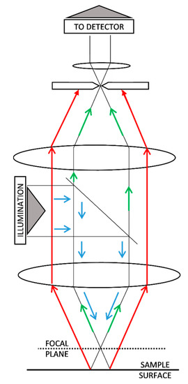
Figure 2.
Filtration of out-of-focus signal (red) in confocal microscopy [5,7,16,17,21] in comparison with in-focus signal (green).
Once the in-focus image goes to the detector, the computational treatment starts. The electronic controller moves the objective along the Z-axis in order to permit the confocal microscope to capture 2D images at different coordinates. As 2D images are composed of pixels, 3D images obtained with confocal microscopes are composed of voxels, as shown in Figure 3. If an interpolation if made between consecutive 2D images, it is possible to create a 3D model of the scanned surface [23].

Figure 3.
Transformation from pixel to voxel.
In order to achieve dimensional traceability in dimensional measurements carried out with confocal microscopes, it is necessary to perform a 3D calibration of the instrument. This calibration should provide estimations of voxel sizes along X, Y, and Z axes, but it would also be advisable to provide estimations of perpendicularity errors between axes. Additionally, as the confocal microscope can be used to perform roughness measurements, a specific calibration of the instrument for roughness measurements is advisable.
2. Materials and Methods
In order to ease the understanding of the calibration procedures described later on, a calibration example was carried with the following confocal microscope and software:
- Leica DCM3D confocal microscope (Wetzlar, Germany) with a 10× objective (EPI-L, NA = 0,30). Field of view 1270 µm × 952 µm (768 × 576 pixels); 1.65 µm nominal voxel width. The overall range of the Z-axis is 944 µm using 2 µm axial steps (voxel height), but the instrument is used in a reduced working range of only 100 µm.
- SensoSCAN—LeicaSCAN DCM3D 3.41.0 software developed by Sensofar Tech Ltd. (Terrassa, Spain).
In this paper, we propose a calibration procedure that is only valid for single topography measurements—that is, without using image stitching. In single topography measurements, the XY stage is not moved during measurement, and its errors do not contribute to uncertainty. When using image stitching (extended topography measurements), the XY stage does contribute to uncertainty, and the calibration procedure described in this paper should be updated using techniques such as those described in [14,15]. The complete calibration procedure includes the following:
- Calibration of the X and Y scales, using a stage micrometer as a reference measurement standard.
- Estimation of perpendicularity error between X and Y axes.
- Estimation of the flatness deviation of the focal plane using an optical flat.
- Calibration of Z scale using a calibrated steel sphere.
- Calibration of the confocal microscope for the measurement of 2D roughness using periodic and aperiodic 2D roughness measurement standards.
- All uncertainties are estimated following the mainstream GUM method (Guide to the Expression of Uncertainty in Measurement [24]) or EA-04/02 M:2013 document [25], as they are standard procedures in calibration laboratories accredited under ISO 17025 [26].
All reference measurement standards used were chosen to be:
- Easy to find.
- Easy to calibrate with low enough uncertainties in National Measurement Institutes (NMIs) or preferably in accredited calibration laboratories (ACLs).
- Stable mechanical artifacts that could guarantee long recalibration intervals.
- Common in the field of dimensional metrology in order to facilitate their acquisition, calibration, and correct use.
2.1. Flatness Verification
Before calibrating the X and Y axes, a flatness verification must be performed. This is necessary because it is often observed that the XY plane of confocal microscopes is slightly curved. This is evident when exploring a flat surface such as an optical flat whose total flatness error is usually lower than 50 nm. In these cases, the reference flat surface when observed by the confocal microscope appears curved, as if it was a cap of a sphere or an ellipsoid. According to manufacturers, this error is usually small enough, but it is impossible to carry out an accurate measurement without taking this component of uncertainty into account [27].
For this verification, the authors propose following a procedure based on [28], but using a confocal microscope instead of an interferometer. The software of the confocal microscope provides a topographic map of the explored surface from which the total flatness error (peak to peak) or the RMS (root mean square error) flatness can be estimated.
The calibration is done in two positions (0° and 90°) and therefore, two measurements are obtained (Figure 4):
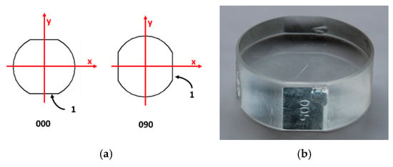
Figure 4.
(a) Positions of the optical flat during calibration; (b) optical flat.
For this calibration, the authors recommend using the RMS flatness deviation, because it is more statistically stable than the total flatness deviation. As discussed in [29] (Section 1.3.5.6 “Measures of Scale”), the total flatness deviation—which is equivalent to the range—is very sensible to the presence of outliers because it is determined as the difference between the two most extreme points. The problem increases with the number of points from which the range is determined. In our case, the number of points was very large (. For these reasons, other parameters such as the standard deviation (equivalent to the root mean square error), or even better, the median absolute deviation (MAD) should be used. Since confocal software always includes the RMS flatness deviation and it is not very easy to include MAD, we recommend the RMS flatness deviation.
2.2. XY Plane Calibration
In the literature, it is possible to find several procedures for this calibration. Following the studies of de Vicente et al. [30] and Guarneros et al. [31], it is possible to calibrate X and Y scales and estimate their perpendicularity error by making measurements of a stage micrometer in four positions (Figure 5).

Figure 5.
(a) The different positions of scanning for the stage micrometer; (b) the stage micrometer used during calibration.
A stage micrometer is easy to calibrate in a National Measurement Institute (NMI) or in an accredited calibration laboratory (ACL) with sufficiently small uncertainty (equal to or lower than 1 µm) for the calibration of a confocal microscope.
It is strongly recommended that the stage micrometer should be metallic and have the marks engraved, not painted, such as those used to calibrate metallographic microscopes. Marks painted over glass are difficult to detect with a confocal instrument.
The matrix model proposed for calibration by de Vicente et al. [32] is as follows:
where are the readings directly provided by the confocal microscope for the Cartesian coordinates in the XY plane. are the corrected Cartesian coordinates once the calibration parameters , and have been applied using the previous matrix model.
The meanings of these three parameters are as follows:
represents the deviation of actual pixel width from the nominal pixel width :
represents the difference between pixel widths along X-axis () and Y-axis ():
represents the perpendicularity error between the X-axis and Y-axis. The actual angle between these axes is .
The amplification coefficients, , and of the axes (according to ISO 25178-70 [33]) are:
We recommend using the average pitch of the stage micrometers. is the average of all individual pitches (distances between two consecutive marks) observed in the images provided by the confocal microscope. Figure 6 summarizes the measurement of the stage micrometer in one position. Using special software for this task, written in Matlab® R2019a and developed at the Laboratorio de Metrología y Metrotecnia (LMM), it is possible to automatically detect and estimate the distance of each mark from the zero mark. Using this software, all the distances (pitches) between two consecutive marks in the stage micrometers were estimated (Figure 6a). Moreover, pitches can be measured in different positions—in the middle and in higher and lower positions—which permits the estimation of the repeatability during the pitch measurements. In Figure 6a, for each pitch, the average value is represented by a circle, and the measurement variability around this value is represented with a vertical line. In order to estimate the non-linearity errors (Figure 6b), a straight line was fitted, and the errors were estimated as . The coefficient represents the deviation of the zero mark from its estimated position and represents the average pitch.
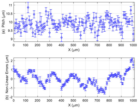
Figure 6.
Measurement of stage micrometer in position 0°: (a) pitch measurements results in µm; (b) non-linear errors in µm.
If the previously mentioned special software is not available, measurements of distances between marks must be done by hand. However, although it is more laborious, the entire procedure described above for the estimation of the average pitch and non-linearity errors can be carried out without any problem.
Let be the average pitch of the stage micrometer certified by a suitable laboratory with a standard uncertainty . , , , and are the average pitches measured with the confocal microscope in positions 0°, 90°, 45°, and 135°, respectively. Their corresponding standard uncertainties are , , , and where only the variability observed in Figure 6 (or equivalent ones) was taken into account.
When the matrix model is applied to positions 0°, 90°, 45°, and 135°, we obtain the following expressions that permit simple estimations of calibration parameters , and :
From these expressions, it is easy to conclude that possible estimations of,andare:
Correlations between these parameters (,and) are usually very small (lower than 0.01). Therefore, these correlations can be neglected.
2.3. Z-Axis Calibration
Document [34] proposes calibrating the Z-axis using a step gauge built with gauge blocks over an optical flat (Figure 7). However, the short field of view of confocal microscopes makes it difficult to carry out the calibration with this type of measurement standard.
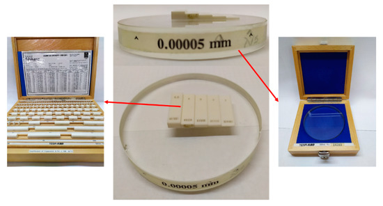
Figure 7.
A step gauge built on an optical flat (with total flatness error 0.00005 mm) and a set of gauge blocks.
To solve this problem, several authors [5,35] have proposed the use of step height standards (Figure 8). Wang et al. [35] used them with the nominal values 24, 7, 2, and 0.7 µm. This kind of measurement standard has several grooves whose nominal depths cover the range of use of the confocal microscope on the Z-axis. Following their procedures, every groove has to be measured 10 times, changing the position of the standard on the objective.
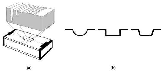
Figure 8.
This figure shows (a) a typical model of a step height standard; and (b) different models of step height standards’ grooves (ISO 5436-1 types A and B) [30,35,36,37].
This kind of standard is typically used for roughness calibration. If the purpose is to make a calibration on the Z-axis, these standards have the limitation of the groove depth, which usually is small to cover the range of the Z-axis.
In order to solve this problem, we propose using a small metallic sphere, as shown in Figure 9, with a nominal diameter between 1 and 10 mm, similar to the one used in [38]. This kind of measurement standard is easy to find and easy to calibrate in both NMIs and ACLs with uncertainties equal to or lower than 0.5 µm. The software of confocal microscopes usually permits a spherical surface to be fit to the points detected over the surface of the spherical measurement standard. If not, coordinates obtained with the confocal microscope can be exported to a text file and processed with a routine similar to that described in Appendix A. Therefore, it is possible to compare the certified diameter of the sphere against the diameter of the spherical surface fitted by the confocal microscope. We propose the use of an extended matrix model to take into account the calibration of the Z-axis:
where are readings provided by the confocal microscope for the Cartesian coordinates. The calibration parameters are those described in Section 2.2 (), and the new parameter is introduced to permit the calibration in the Z-axis. The corrected coordinate is:
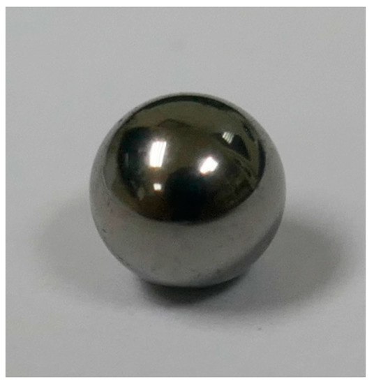
Figure 9.
Steel sphere used in calibration.
This simple matrix model supposes that there is no (or negligible) perpendicular error between the Z-axis and the XY plane. This hypothesis is very close to reality when the Z-axis range is clearly lower than ranges of the X and Y axes. When the Z-axis range is equal to or greater than X and Y ranges, a more complex model must be used (zero terms in the matrix of the model are no longer zero—see, for example, [39]). It is easy to demonstrate that, using the matrix model, the corrected diameter of the spherical surface fitted by the confocal microscope software is:
where is the diameter provided by the confocal microscope prior to applying any calibration parameter. Therefore, an estimation of is
where is the certified diameter of the sphere by the ACL. The standard uncertainty of is
Equation (22) of shows a clear positive dependency with. Therefore, the correlation coefficient should be estimated, and it can be done using the following expression:
Note that the correlation coefficient is denoted as . Do not confuse it with the reading of the confocal microscope for the Z-axis, which is denoted as .
2.4. Calibration for Roughness Measurements
The calibration of the Z-axis against the reference sphere (previous section) guarantees the traceability of the vertical measurements performed with the confocal microscope to the SI unit of length (the meter). Therefore, any vertical roughness parameter will have an adequate traceability once the instrument has been calibrated along its Z-axis. Notwithstanding, we followed the recommendation included in documents DKD-R 4-2 [40,41,42], which propose performing an additional calibration against roughness standards to validate the Z-axis calibration for roughness measurements.
Many parameters are used to characterize surface texture. Among the 2D roughness parameters, one of the most widely used is the parameter, which is the arithmetic mean of the absolute values of the profile deviations from the mean line of the roughness profile [43]. We only consider theparameter during calibration, but readers interested in other 2D roughness vertical parameters (, , , , …) can use the same calibration procedure described in this paper but with minor variations. Calibration was performed in the range µm. For this range, according to ISO 4288 [44], the sampling length should be = 0.8 mm, which is possible to carry out with a field of view of 1270 µm × 952 µm. For µm, the sampling length should be = 2.5 mm or higher, and it is impossible to achieve this with a field of view of 1270 µm × 952 µm (10× objective). It makes no sense to measure roughness lower than µm with an instrument with repeatability in the Z-axis of around 0.5 µm. Therefore, calibration for µm and µm was discarded.
Figure 10a shows three metallic, aperiodic 2D roughness standards. Figure 10b shows three glass, periodic 2D roughness standards. Other types of 2D roughness profile types are described in Section 7 of ISO 25178-70 [33]. We recommend the use of aperiodic standards because they cover a wide range of wavelengths, in contrast to periodic standards that only cover a single wavelength. However, periodic standards were used in this case in order to complete the range of measurements between 0.1 µm and 2 µm for different calibration points and for different materials (glass instead of metallic items).

Figure 10.
Step height standards used during calibration: (a) aperiodic, metallic standards and (b) periodic, glass standards.
These standards were measured over five different zones in two different orientations (Figure 11a,b). In each zone, the measurement was carried out along a line perpendicular to the roughness lines (Figure 11c) and located at the center of the zone. Therefore, a total of roughness measurements were obtained from each standard.
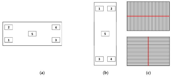
Figure 11.
Location of the five scanning positions for roughness calibration: (a) horizontal orientation; (b) vertical orientation; and (c) location of measurement lines.
We recommend using at least three different roughness standards with nominal values of uniformly distributed along the range where the instrument must be calibrated. However, it is advisable to use five or more standards and, if possible, standards made of different materials (e.g., metallic and glass).
It is important to note that there will be differences between measurements obtained with a confocal microscope and measurements obtained with a stylus instrument [4,45].
The main reasons for this are as follows.
- The way the surface is detected is totally different: microscopes use light, and stylus instruments use a mechanical tip. Usually, optical instruments present higher instrument noise than stylus instruments. Possible reasons are the effects of multiple scattering and discontinuities [45]. As a consequence, optical instruments tend to overestimate surface roughness.
- Stylus instruments permit evaluation lengths that are as long as necessary (see ISO 4288 [44]). Microscopes usually have small fields of view that limit the maximum length of the profile that can be scanned. For example, for samples with 0.1 µm 2 µm, ISO 4288 recommends using five sampling lengths mm for a total evaluation length mm. This is not a problem for stylus instruments, which can cope with longer evaluation lengths (up to 100 mm in some cases). However, the confocal microscope described at the beginning of Section 2 has a maximum evaluation length of 1.27 mm. Therefore, only one sampling length mm could be used. Using only one sampling length instead of five usually causes a bias toward lower values, which are accompanied by an increase in variability. The effect is considerably higher when even the sampling length has to be reduced.
In order to ensure a good match between roughness measurements performed with stylus instruments and optical instruments, the concept of “bandwidth matching” should be correctly applied. This term refers to the good correspondence between the spectral bandwidths of two different instruments used for roughness measurements [45]. The effective spectral bandwidth of a roughness-measuring instrument is limited by the two cut-off wavelengths, (a high-pass filter), and (a low-pass filter), and it is influenced by the X-axis resolution and tip radius in stylus instruments or lateral resolution and pixel size in optical instruments.
2.5. Summary of Characteristics of Measurement Standards Used during Calibration
In this section, the nominal values and the uncertainties of the different reference measurement standards used during calibration are summarized. All of them were calibrated in ACLs.
We include the calibration of the confocal microscope against roughness standard #6 only for informative purposes. Its measurements were made using a sampling length of mm because of the reduced field of view of the instrument (with an 10× objective). However, ISO 4288 [44] recommends the use of a sampling length mm, which is a measurement that is impossible to achieve with a 10× objective.
3. Results
3.1. Flatness Verification
The following figure shows a topographic image of the optical flat of Figure 4 that was used as a flatness calibration surface. This optical flat was previously calibrated in an accredited laboratory. The total flatness error was 118 nm with a standard uncertainty of 25 nm (), and its RMS flatness was 28 nm with a standard uncertainty of 7 nm (); see Table 1.

Table 1.
Nominal values and the uncertainties of the material reference standards used during calibration.1 is a spacing parameter defined as the mean spacing between peaks. values included in this table are only informative. RMS: root mean square error.
Figure 12 shows the absence of significant curvature in the XY plane. A slight uncorrected curvature of about 0.6 µm (peak to peak) was observed, which is small and could be neglected when compared with the Z-axis axial step (2.0 µm) and observed instrument noise (about 1.0 µm peak to peak). This could be an empirical demonstration of a good adjustment and/or correction of the microscope by the manufacturer. In a situation such as this, there is no need to apply any further correction to compensate the curvature of the XY plane.
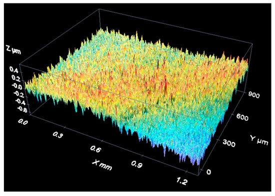
Figure 12.
Result of the flatness measurement performed over the optical flat.
Table 2 shows the results of the measurements performed with the confocal microscope (in both positions 0° and 90°).

Table 2.
RMS flatness measured with the confocal microscope in positions 0° and 90°.
The RMS values of Table 2 are small when compared with the Z-axis axial step of 2.0 µm. Therefore, they were probably caused by the lack of repeatability of the instrument. In any case, the most conservative option is to estimate a component of the uncertainty associated with the possible curvature of the XY plane equal to the average value of both RMS values of Table 2:
A better estimation for would likely be to quadratically subtract the RMS flatness of the optical flat ( µm):
Regardless, we considered that the first estimation ( µm) is slightly more conservative and clearly simpler.
3.2. XY Plane Calibration
Figure 13 shows the four positions (0°, 45°, 90°, 135°) in which the stage micrometer was measured in the confocal microscope during the XY plane calibration.

Figure 13.
Different measurement positions (0°, 45°, 90°, 135°) of the stage micrometer.
In each position, the average pitch was determined from readings provided by the confocal microscope. The results are shown in Table 3.

Table 3.
Measurements of the average pitch in different orientations.
The average value for repeatability in the XY plane was = 0.4 µm. This is a reasonable value when compared with the 1.65 µm lateral resolution (nominal voxel width).
The stage micrometer had a certified average pitch = 9.980 µm with a standard uncertainty = 0.005 µm.
Using the expression for Section 2.2, we obtained the following estimations for calibration parameters, and:
All three parameters are dimensionless.
Observing the non-linearity RMS values in Table 3, the overall standard uncertainty estimation for non-linearity in the XY-plane was µm.
3.3. Z-Axis Calibration
Figure 14 shows an example of a measurement of the spherical cap of a stainless steel reference sphere with a 4-mm nominal diameter (see Figure 9). It is a three-dimensional reconstruction of the sphere surface.
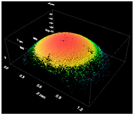
Figure 14.
Results of the measurement of a bearing sphere with white light.
Using this information, the confocal microscope software can perform a least-square fitting to a spherical surface from which we could estimate the diameter of the sphere and RMS error of the fit. If the confocal software does not permit fitting a spherical surface, a code similar to the one described and listed in Appendix A can be used.
In this calibration, two different types of illumination were used (white and blue light), and measurements were taken in three orientations: 0°, 45°, and 90°. Finally, there were measurements. Results obtained during the measurement of the bearing steel sphere of Figure 9 are presented in Table 4.

Table 4.
Root mean square error and diameter of the spherical caps fitted using least squares.
The average value of the six diameters was = 3.9712 mm, and the standard deviation was 0.0096 mm. We estimated as:
The RMS error is an estimation of the repeatability in the Z-axis, which probably includes the non-linearity in the Z-axis. The mean value for this Z-axis repeatability was = 0.8 µm, which seems to be a reasonable value when compared with the Z-axis axial step of 2 µm.
The certified diameter of the reference sphere was = 4.0011 mm with a standard uncertainty = 0.25 µm.
Using the expression of Section 2.3, the Z-axis calibration parameter can be estimated as follows:
The correlation coefficient was
This correlation coefficient is clearly higher than zero, showing a strong positive correlation between and that should be taken into account after calibration when needed. Correlation coefficients and are usually very small (lower than 0.01); therefore, correlation between and parameters and could be neglected.
3.4. Calibration for Roughness Measurements
As an example of data acquisition results when measuring a material roughness standard, the following figures show three-dimensional reconstructions of the surface of an aperiodic, metallic roughness standard (Figure 15) and a periodic, glass roughness standard (Figure 16).
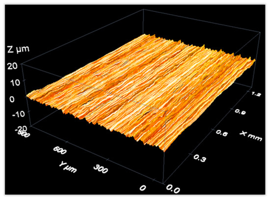
Figure 15.
Measurement of an aperiodic roughness standard with a confocal microscope: 3D view of the measurement results.
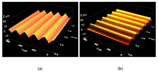
Figure 16.
Measurement of a periodic roughness standard with a confocal microscope: 3D view of the measurement results with roughness lines (a) parallel to the X-axis and (b) parallel to the Y-axis.
Calibration was performed by repeating the measurements of six roughness standards 10 times (five zones, two orientations; see Table 1). The results are summarized in Table 5, showing average results of the 10 repeated measurements and corresponding standard deviations . Direct readings provided by the confocal microscope were obtained prior to introducing the calibration parameter using only one sampling length mm.

Therefore, these readings should be corrected by applying the following expression to take into account the Z-axis calibration:
The authors followed the recommendations of ISO 4288 [44] that, for mm, recommend five sampling lengths mm for a total evaluation length of . Due to the limitations of the instrument’s field of view (see Section 2), only one sampling length mm could be used. This reduction in the number of sampling lengths from five to one caused slightly lower values for and higher variabilities [45].
It can be concluded from Table 5 that a typical value for was μm, which was the quadratic average of repeatabilities of the first five standards.
Note that corrected values were always higher than the certified values (compare the results from Table 5 to those from Table 1). It seems that for surface roughness similar to the nominal voxel height ( μm), readings provided by the confocal microscope presented a positive bias caused by noise observed, for example, when measuring an optical flat (see Section 3.1, Figure 12). The RMS flatness observed when measuring the optical flat (0.54 µm) was slightly higher than the values that were observed when measuring roughness standard #1, which is a quasi-flat surface (certified value μm) for an instrument with a voxel height of μm. The definition of is similar but not equal to the definition of RMS flatness, but most importantly, was evaluated after filtering the readings using a low-pass filter (defined through the sampling length).
We suggest estimating the positive bias at each calibration point using the following expression, where is the certified value for the standard used at each calibration point:
Its corresponding standard uncertainty is:
Using this approach, the calibration results are those values, and which are presented in the two columns on the right side of Table 5. Index refers to the roughness standard used. These results are represented graphically in Figure 17 in order to analyze their metrological compatibility. Red lines represent values corresponding to metallic, aperiodic standards #1, #2, and #3. Green lines represent values corresponding to standards #4 and #5. The blue line is the result from standard #6 that will not be taken into account. Vertical lines represents uncertainty intervals where the expanded uncertainties were evaluated for a coverage factor (see Section 6.2.1 in [24] for definitions of coverage factor and expanded uncertainty). When analyzing the compatibility between measurement results, it is very common to use a coverage factor of to estimate the expanded uncertainties. The horizontal black solid line in Figure 17 corresponds to the average value of the first roughness standards:
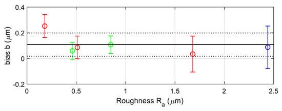
Figure 17.
Bias observed at each calibration point (roughness calibration).
In order to make a correct estimation of average bias , the correlation between bias at each calibration points should be taken into account for the following reasons:
- Dominant contributions to uncertainties are the calibration uncertainties of the roughness standards.
- There is a high probability that all roughness standards were calibrated in the same calibration laboratory. Therefore, there will be strong correlation between them.
There will be a high correlation between bias . We performed estimations in different situations, and it is possible to see correlation coefficients as high as +0.8.
In order to simplify calculations, we suggest assuming, which leads to higher estimations for the uncertainty of . Then, it can be demonstrated that was:
In Figure 17, the uncertainty interval is represented by the space between the higher and lower black dotted lines. is the expanded uncertainty of evaluated with a coverage factor . Please note that all the uncertainty intervals overlap the interval . Notwithstanding, point is outside the interval . This could indicate that some variability of the bias was not taken into account in. Therefore, a conservative approach would be to assume that there is a variability represented by that should be added to. Suppose that is a uniform random variable of null mean and a full range. Then, its standard uncertainty would be:
In order to estimate the noise of the instrument, according to [40,41,42], we repeated 10 measurements over an optical flat (that of Figure 4) in two orientations: 0° and 90°. For a confocal microscope, an optical flat is a specimen with null roughness (very small in comparison with its noise). Therefore, values of obtained over an optical flat are a very good estimation of the instrument noise. The average value and the standard deviation of the 10 values were
Therefore, a good estimation for the uncertainty component associated with noise instrument is
4. Discussion

Table 6.
Results of calibration.
Note that these results are only valid for measurements made with the same objective (10×). If other objectives are used, a whole recalibration is needed for each new objective.
The effects and their uncertainties were the highest for parameters and . If their effects were not corrected, their contribution to the relative expanded uncertainty would be around 1%.
Fortunately, the software of confocal microscopes usually permits users to introduce their value in order to compensate their effects. If this compensation is done, their contribution to the relative expanded uncertainty is reduced to 0.3%.
The effect of parameter (difference between pixel lengths along X and Y axes) was negligible. Its absolute value was lower than its expanded uncertainty (for ); therefore, the null hypothesis could not be rejected. Its contribution to the relative expanded uncertainty was very low (around 0.01%).
The effect of parameter (perpendicularity error between X and Y axes) seemed to be significant (its absolute value was clearly higher than its expanded uncertainty), but its contribution to the relative expanded uncertainty (around 0.1%) was clearly negligible in comparison with and .
The contributions of XY plane RMS flatness ( and the non-linearity in X and Y axes were clearly lower than the voxel dimensions ( μm and μm). Therefore, the instrument adjustment performed by the manufacturer seems to have been good.
Repeatabilities in the XY plane and in the Z-axis, in comparison with the voxels dimensions, were low. Again, this can be used to conclude that the instrument was working well.
In roughness measurements (which only apply when using the parameter), the repeatability, average bias , bias variability), and instrument noise were very small in comparison with voxel height μm.
4.1. Expanded Uncertainty Estimation for Length Measurements in the XY Plane
As was pointed out, the instrument software usually permits users to introduce parameters and in order to apply the corresponding corrections. On the contrary, parameters and cannot be introduced. Therefore, the effect of uncorrected, non-null parameters and would be taken into account as a systematic effect whose equivalent standard uncertainties would respectively be and . We supposed that it was equivalent to the introduction of two components, and , uniformly distributed along and respectively.
For length measurements performed in the XY plane, the following expression could be a good estimate of its expanded uncertainty, where the pixel width component was estimated as (uniformly distributed between ):
Uncertainty components for which no distribution was described were supposed to have normal distributions. In such situations, where there are many uncertainty components (eight components) and most of them are normally distributed and they contribute similarly to the total combined uncertainty, it can be supposed that the output variable is normally distributed [25]. Therefore, a coverage factor can be used when computing the expanded uncertainty, assuming a coverage probability of approximately 95%.
4.2. Expanded Uncertainty Estimation for Height Measurements along the Z-Axis
For height measurement (μm—the Z range approximately covered by the sphere cap measured), the following expression gives us a reasonable estimation of its expanded uncertainty for a coverage factor :
Now there are four uncertainty components, where three are distributed normally, and only one is distributed uniformly, but is never the dominant contribution. Again, in a situation such as this, a coverage factor can be used when computing the expanded uncertainty, assuming a coverage probability of approximately 95% [25].
4.3. Expanded Uncertainty for Roughness Measurements
Following the recommendations of DKD-R 4-2 [40,41,42], a model for a corrected roughness measurement performed after instrument calibration would be:
where now is the average of repeated measurements made over the specimen being measured, and is a random variable of null mean distributed normally with standard deviation . The standard uncertainty of is
The expanded uncertainty , using a coverage factor is
In this case, there are five uncertainty components, is distributed uniformly, and follows a t-Student distribution with degrees of freedom. If we compute the degrees of freedom of the output variable , the result is approximately 30. With , it is possible to use a coverage factor corresponding to a coverage probability of approximately 95% [25]. Then, assuming that measurements will be repeated times, the expanded uncertainty would be
This value is very good for an instrument with a voxel height of μm.
4.4. Propagation of Uncertainty When Measuring the Radius of a Cylindrical Surface
As an example of uncertainty propagation in dimensional measurements not directly covered in Section 4.2 and Section 4.3, we present the case of a measurement of the radius of a cylindrical surface (see Figure 18) of a steel bar with a nominal value of 2.75 mm.
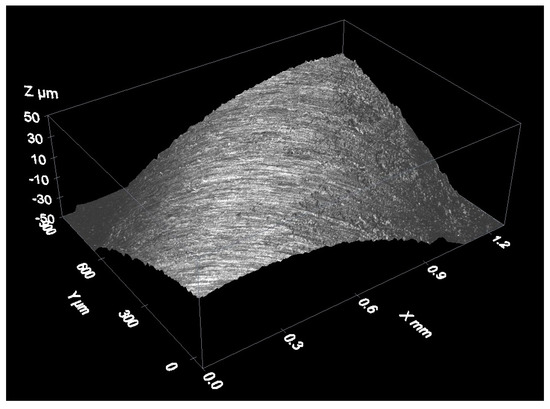
Figure 18.
Measurement of a cylindrical surface.
The uncertainty propagation was done using Monte Carlo simulation [46]. The model function used during the simulation of the coordinates of the surface’s points was the following:
where are the coordinates provided by the confocal microscope during the measurement. They were not simulated. Table 7 enumerates variables that were simulated and how the simulation was performed. Corrections and were not applied, because the instrument software cannot take them into account. In order to take into account the effect of not applying these corrections, and were introduced, and and are supposed to be normal distributions with zero mean (not applying corrections) and typical uncertainty and . and have uniform distribution with zero mean and typical uncertainties and . represent the repeatability effects over coordinates . We supposed that they had normal distributions with zero mean and typical uncertainties and μm, where is the root mean squared error observed when fitting a cylindrical surface to measured points using a least-squares fit.

Table 7.
Variables simulation.1 Corrections and were not applied.
A total of simulations were generated. For each simulation, a value was obtained for the radius of the cylindrical surface. Figure 19 shows the histogram of the simulated radius of the cylindrical surface. The red smooth line represents the best approximation of the histogram through a normal distribution. Differences between the red line and the histogram were small enough to be negligible. It is likely that upon increasing the number of simulations (the advisable value for N when there is no time limit during the execution to the simulation process is [46]), these differences would be smaller. For this reason, a coverage factor (corresponding to an approximate coverage probability of 95%) was chosen in previous sections: final distributions are usually very close to normal distribution where corresponds to a coverage probability of 95.45%.
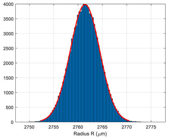
Figure 19.
Histogram of the radius of the cylindrical surface.
The final result was , where the expanded uncertainty , where now is the standard deviation of simulated values . A coverage factor for a coverage probability of approximately 95% was used.
A similar approach could be used to propagate uncertainties when using the confocal microscope for other types of dimensional or angular measurements.
5. Conclusions
A complete calibration procedure that provides adequate traceability to confocal microscopes used in submillimeter coordinate metrology was presented. This procedure provides adequate traceability for length and roughness measurements performed with confocal microscopes and can be easily adapted to calibrate other 3D optical instruments (e.g., focus variation microscopes). The calibration procedure is as simple as possible, as it was designed to be implemented in industrial environments. Reference material standards were chosen to be easy to find and easy to calibrate again in industrial environments. The calibration procedure covers all the key points of operation of a confocal microscope. It permits the estimation of:
- Amplification coefficients , , and .
- Non-linearity errors.
- Perpendicularity error between X and Y axes.
- Relative difference in pixel dimensions along X and Y axes.
- Repeatabilities when measuring lengths or heights.
- Flatness deviations in the XY plane.
- Bias deviation when measuring roughness.
- Instrument noise when measuring roughness.
- Repeatability when measuring roughness.
Some of these parameters (amplification coefficients, flatness deviation in XY plane) can usually be introduced in the instrument software to compensate for their effects. Others cannot be compensated (i.e., ) but if high values are detected, the user can ask the instrument manufacturer to adjust and/or repair the instrument to reduce their effects. Even if they are not introduced, an alternative approach is presented here to account for the fact that these corrections were not applied.
Uncertainty estimations were carried out for all parameters following the mainstream GUM method. In addition, for measurements of lengths and roughness, expressions for expanded uncertainties of measurement carried out by the instrument were provided. There are other types of measurements, such as angular measurements, that were not addressed in this paper due to limitations in the extent of the text. Notwithstanding, all the information needed to propagate uncertainties to these other types of measurements is provided in the paper, as can be demonstrated through an example solved using Monte Carlo simulation.
The procedure described in this paper can be easily adapted to calibrate other optical instruments in the submillimeter range, which are capable of providing 3D information of surfaces being observed by them (e.g., focus variation microscopes). For example, the material of some of the reference material standards would have to be changed, but the core of the procedure would remain the same.
Author Contributions
Conceptualization, A.M.M. and J.d.V.y.O.; Investigation, A.M.M.; Methodology, A.M.M., and J.d.V.y.O.; Software, A.M.M. and J.d.V.y.O.; Supervision, J.d.V.y.O.; Validation, J.d.V.y.O.; Writing—original draft, A.M.M.; Writing—review and editing, J.d.V.y.O.
Funding
This research received no external funding.
Conflicts of Interest
The authors declare no conflicts of interest.
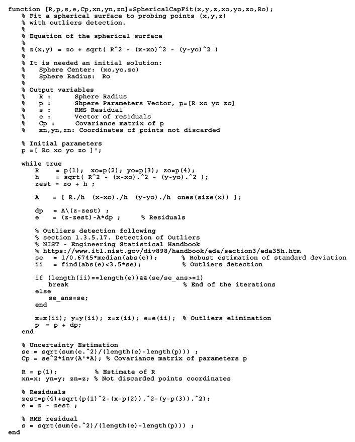
Appendix A. Algorithm for Spherical Cap Fitting
At the end of this appendix, we include the source code of a routine written to be executed in Matlab® (www.mathworks.com) or GNU Octave (www.gnu.org/software/octave/) that performs a least-squares fitting of points with Cartesian coordinates to a spherical surface of radius and center at . The following equation is used to describe the surface:
Vector stores the four parameters that define the spherical surface.
This expression works well when performing a least-square fitting when points are over a spherical cap near (sphere north pole) or (sphere south pole).
The algorithm needs an initial solution from which starts an iterative process. In each iteration , the following system of equations is solved by least squares:
where and .
In each iteration, a detection of outliers is made following the method described in Section 1.3.5.17 of [29]. The z coordinates obtained with a confocal microscope are usually noisy enough to make the adjustment by least squares of the surface very difficult. Therefore, a good outlier detection algorithm must be used. The iterative process finishes when no more outliers are detected and no decrease in RMS residual is observed.
References
- Carmignato, S.; Voltan, A.; Savio, E. Metrological performance of optical coordinate measuring machines under industrial conditions. CIRP Ann. Manuf. Technol. 2010, 59, 497–500. [Google Scholar] [CrossRef]
- European Committee for Standardization (CEN). ISO 3274:1996 Geometrical Product Specifications (GPS) Surface Texture: Profile Method. Nominal Characteristics of Contact (stylus) Instruments; CEN: Bruxelles, Belgium, 1996. [Google Scholar]
- Leach, R.K. Towards a complete framework for calibration of optical surface and coordinate measuring instruments. In Proceedings of the SPIE Optical Metrology Plenary Session, ICM, Munich, Germany, 26 June 2019. [Google Scholar]
- European Committee for Standardization (CEN). ISO 25178-6:2010 Geometrical Product Specification (GPS) Surface Texture: Areal—Part 6: Classification Methods for Measuring Surface Texture; CEN: Bruxelles, Belgium, 2010. [Google Scholar]
- Giusca, C.; Leach, R.K. Measurement Good Practice Guide (No. 128): Calibration of the Metrological Characteristics of Imaging Confocal Microscopes (ICMs); National Physical Laboratory (NPL): Teddington, UK, 2012. [Google Scholar]
- Minsky, M. Memoir on Inventing the Confocal Scanning Microscope. Scanning 1988, 10. [Google Scholar] [CrossRef]
- Claxton, N.S.; Fellers, T.J.; Davidson, M.W. Laser scanning confocal microscopy. In Encyclopedia of Medical Devices and Instrumentation, 2nd ed.; Webster, J.G., Ed.; John Wiley & Sons, Inc.: Hoboken, NJ, USA, 2006; pp. 1–37. [Google Scholar] [CrossRef]
- Watson, T. Fact and Artefact in Confocal Microscopy. Adv. Dent. Res. 1997, 11, 128–138. [Google Scholar] [CrossRef]
- Cheng, C.; Wang, J.; Leach, R.K.; Lu, W.; Liu, X.; Jiang, X. Corrected parabolic fitting for height extraction in confocal microscopy. Opt. Express 2019, 27, 3682–3697. [Google Scholar] [CrossRef]
- Alburayt, A.; Syam, W.P.; Leach, R.K. Lateral scale calibration for focus variation microscopy. Meas. Sci. Technol. 2019, 29. [Google Scholar] [CrossRef]
- Joint Committee for Guides in Metrology (JCGM). International Vocabulary of Metrology (VIM)—Basic and General Concepts and Associated Terms, 3rd ed.; JCGM: Paris, France, 2012. [Google Scholar]
- Leach, R.K.; Giusca, C.; Haitjema, H.; Evans, C.; Jiang, X. Calibration and verification of areal surface texture measuring instruments. CIRP Ann. Manuf. Technol. 2015, 64, 797–813. [Google Scholar] [CrossRef]
- Caja, J.; Sanz, A.; Maresca, P.; Fernández, T.; Wang, C. Some Considerations about the Use of Contact and Confocal Microscopy Methods in Surface Texture Measurement. Materials 2018, 11, 1484. [Google Scholar] [CrossRef]
- Wang, C.; Gómez, E.; Yu, Y. Characterization and correction of the geometric errors in using confocal microscope for extended topography measurement. Part I: Models, Algorithms Development and Validation. Electronics 2019, 8, 733. [Google Scholar] [CrossRef]
- Wang, C.; Gómez, E.; Yu, Y. Characterization and Correction of the Geometric Errors Using a Confocal Microscope for Extended Topography Measurement, Part II: Experimental Study and Uncertainty Evaluation. Electronics 2019, 8, 1217. [Google Scholar] [CrossRef]
- Webb, R.H. Confocal optical microscopy. Rep. Prog. Phys. 1996, 59, 427–471. [Google Scholar] [CrossRef]
- Webb, R.H. Theoretical Basis of Confocal Microscopy. Meth. Enzymol. 1999, 307, 3–20. [Google Scholar] [CrossRef] [PubMed]
- Salerni, G. Uso de la microscopía confocal de reflectancia en dermatología. Dermatol. Argent. 2011, 17, 230–235. [Google Scholar]
- Confocal Microscopy, Molecular Expressions. Available online: https://micro.magnet.fsu.edu/primer/techniques/confocal/index.html (accessed on 26 October 2019).
- Leach, R.K.; Bourell, D.; Carmignato, S.; Donmez, A.; Senin, N.; Dewulf, W. Geometrical metrology for metal additive manufacturing. CIRP Ann. Manuf. Technol. 2019, 68, 677–700. [Google Scholar] [CrossRef]
- Introduction to Confocal Microscopy. Available online: https://www.olympus-lifescience.com/en/microscope-resource/primer/techniques/confocal/confocalintro/ (accessed on 26 October 2019).
- Tata, B.V.R.; Raj, B. Confocal laser scanning microscopy: Applications in material science and technology. Bull. Mater. Sci. 1998, 21, 263–278. [Google Scholar] [CrossRef]
- Cohen-Or, D.; Kaufmann, A. Fundamentals of Surface Voxelization. CVGIP: Graph. Model. Image Process. 1995, 57, 453–461. [Google Scholar] [CrossRef]
- Joint Committee for Guides in Metrology, Working Group 1 (JCGM/WG 1). JCGM 100:2008 Evaluation of Measurement Data—Guide to the Expression of Uncertainty in Measurement (GUM), 1st ed.; JCGM: Paris, France, 2008. [Google Scholar]
- European Accreditation (EA). EA-4/02—Evaluation of the Uncertainty of Measurement in Calibration; EA: London, UK, 2013. [Google Scholar]
- European Committee for Standardization (CEN). ISO/IEC 17025:2017 General Requirements for the Competence of Testing and Calibration; CEN: Bruxelles, Belgium, 2017. [Google Scholar]
- SENSOFAR-TECH LTD. Application Note: Flatness Error on Imaging Confocal Microscopes; Sensofar: Tarrasa, Spain, 2009. [Google Scholar]
- Centro Español de Metrología (CEM). Procedimiento DI-035 para la Calibración de Patrones de Planitud de Vidrio; CEM: Madrid, Spain, 2004. [Google Scholar]
- NIST/SEMATECH e-Handbook of Statistical Methods. Available online: http://www.itl.nist.gov/div898/handbook/ (accessed on 27 November 2019).
- De Vicente, J.; Molpeceres, C.; Guarneros, O.; García-Ballesteros, J. Calibración de Microscopios Confocales; XVII National Congress of Mechanical Engineering: Gijón, Spain, 2008. [Google Scholar]
- Guarneros, O.; De Vicente, J.; Maya, M.; Ocaña, J.L.; Molpeceres, C.; García-Ballesteros, J.; Rodríguez, S.; Duran, H. Uncertainty Estimation for Performance Evaluation of a Confocal Microscope as Metrology Equipment. MAPAN—J. Metrol. Soc. I 2014, 29, 29–42. [Google Scholar] [CrossRef]
- De Vicente, J.; Sánchez-Pérez, A.M.; Maresca, P.; Caja, J.; Gómez, E. A model to transform a commercial flatbed scanner into a two-coordinates measuring machine. Measurement 2015, 73, 304–312. [Google Scholar] [CrossRef]
- European Committee for Standardization (CEN). ISO 25178-70 Geometrical Product Specification (GPS) Surface Texture: Areal—Part 70: Material Measures; CEN: Bruxelles, Belgium, 2014. [Google Scholar]
- Centro Español de Metrología (CEM). Procedimiento DI-004 para la Calibración de Medidoras de una Coordenada Vertical; CEM: Madrid, Spain, 2013. [Google Scholar]
- Wang, C.; Caja, J.; Gómez, E.; Maresca, P. Procedure for Calibrating the Z-axis of a Confocal Microscope: Application for the Evaluation of Structured Surfaces. Sensors 2019, 19, 527. [Google Scholar] [CrossRef] [PubMed]
- European Committee for Standardization (CEN). ISO 5436-1:2000 Geometrical Product Specipications (GPS) Surface Texture: Profile Method. Measurement Standards—Part 1: Material Measures; CEN: Bruxelles, Belgium, 2000. [Google Scholar]
- Calibration standards, HALLE Präzisions-Kalibriernormale GmbH. Available online: http://halle-normale.de/framesets/englisch/products/products.html (accessed on 29 October 2019).
- Balcon, M.; Carmignato, S.; Savio, E. Performance verification of a confocal microscope for 3D metrology tasks. Qual.—Access Success 2012, 13, 63–66. [Google Scholar]
- De Vicente, J.; Raya, F. Simplified Statistical Method for Uncertainty Estimation in Coordinate Metrology. In Proceedings of the 9th International Metrology Congress, Bordeaux, France, 18–21 October 1999. [Google Scholar]
- Deutscher Kalibrierdienst (DKD). Guideline DKD 4-2 Calibration of Measuring Instruments and Standards for Roughness Measuring Technique (Sheet 1: Calibration of Standards for Roughness Measuring Technique); DKD: Braunschweig, Germany, 2011. [Google Scholar]
- Deutscher Kalibrierdienst (DKD). Guideline DKD-R 4-2 Calibration of Devices and Standards for Roughness Metrology (Sheet 2: Calibration of the Vertical Measuring System of Stylus Instrument); DKD: Braunschweig, Germany, 2011. [Google Scholar]
- Deutscher Kalibrierdienst (DKD). Guideline DKD-R 4-2 Calibration of Devices and Standards for Roughness Metrology (Sheet 3: Calibration of Standards with Periodic Profiles in Horizontal Direction by Means of Stylus Instrument); DKD: Braunschweig, Germany, 2011. [Google Scholar]
- European Committee for Standardization (CEN). ISO 4287:1999 Geometrical Product Specifications (GPS) Surface Texture: Profile Method. Terms, Definitions and Surface Texture Parameters; CEN: Bruxelles, Belgium, 1999. [Google Scholar]
- European Committee for Standardization (CEN). ISO 4288:1996 Geometrical Product Specifications (GPS) Surface Texture: Profile Method. Rules and Procedures for the Assessment of Surface Texture; CEN: Bruxelles, Belgium, 1996. [Google Scholar]
- Leach, R.K.; Haitjema, H. Bandwidth characteristics and comparisons of surface texture measuring instruments. Meas. Sci. Technol. 2010, 21. [Google Scholar] [CrossRef]
- Joint Committee for Guides in Metrology, Working Group 1 (JCGM/WG 1). JCGM 101:2008 Evaluation of Measurement Data—Supplement 1 to the “Guide to the Expression of Uncertainty in Measurement”—Propagation of Distributions using a Monte Carlo Method (GUM-S1), 1st ed.; JCGM: Paris, France, 2008. [Google Scholar]
© 2019 by the authors. Licensee MDPI, Basel, Switzerland. This article is an open access article distributed under the terms and conditions of the Creative Commons Attribution (CC BY) license (http://creativecommons.org/licenses/by/4.0/).