The Influence of A Mo Addition on the Interfacial Morphologies and Corrosion Resistances of Novel Fe-Cr-B Alloys Immersed in Molten Aluminum


Abstract
:1. Introduction
2. Materials and Methods
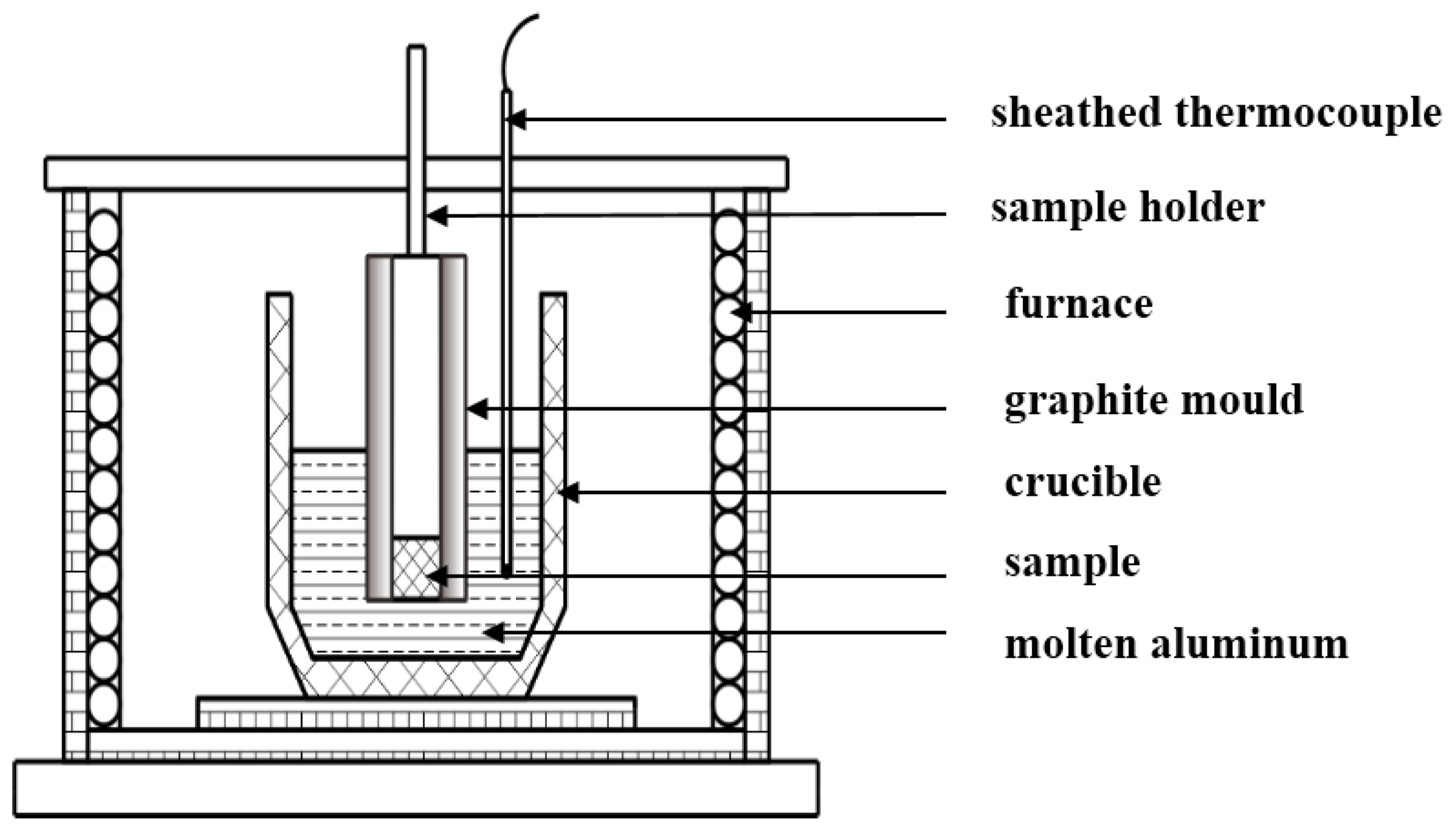
2.1. Material Preparation
2.2. Material Preparation
2.3. Microstructure Characteristics
3. Results and Discussion
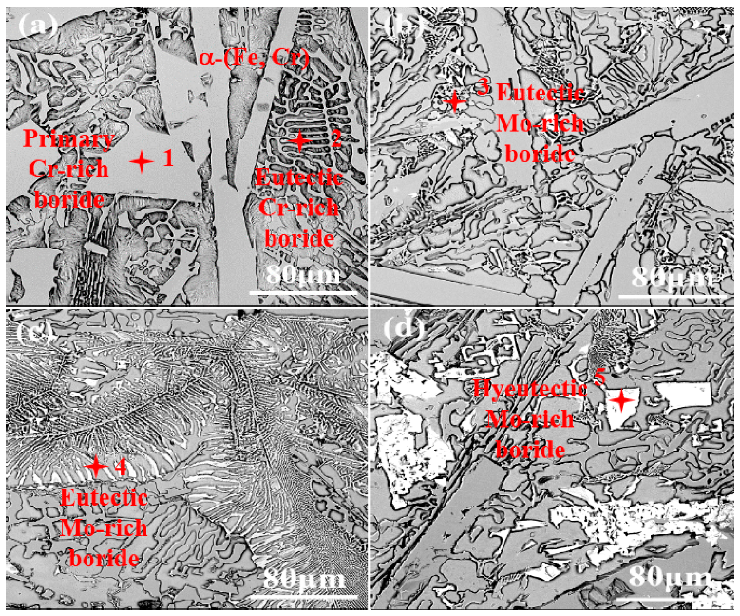
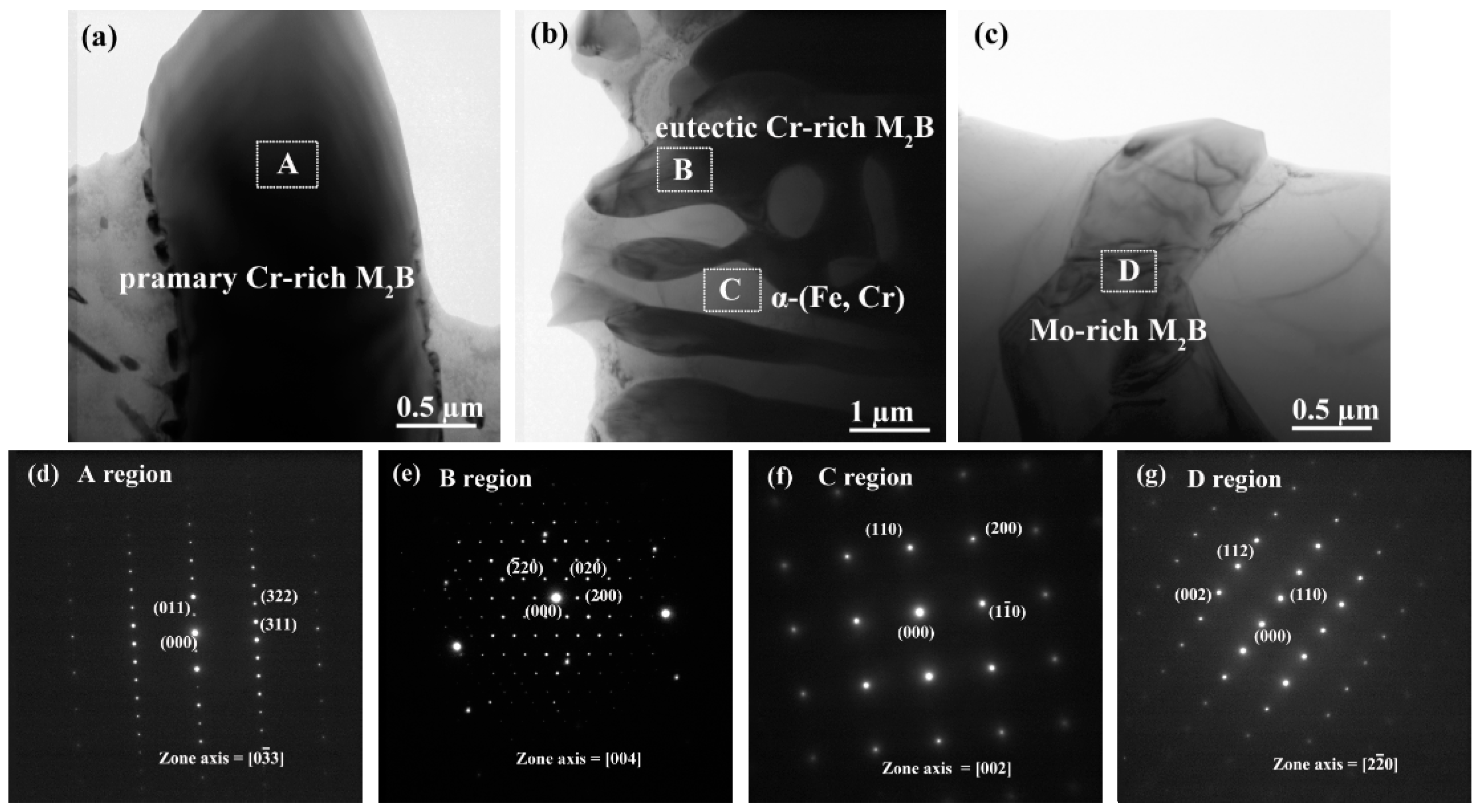
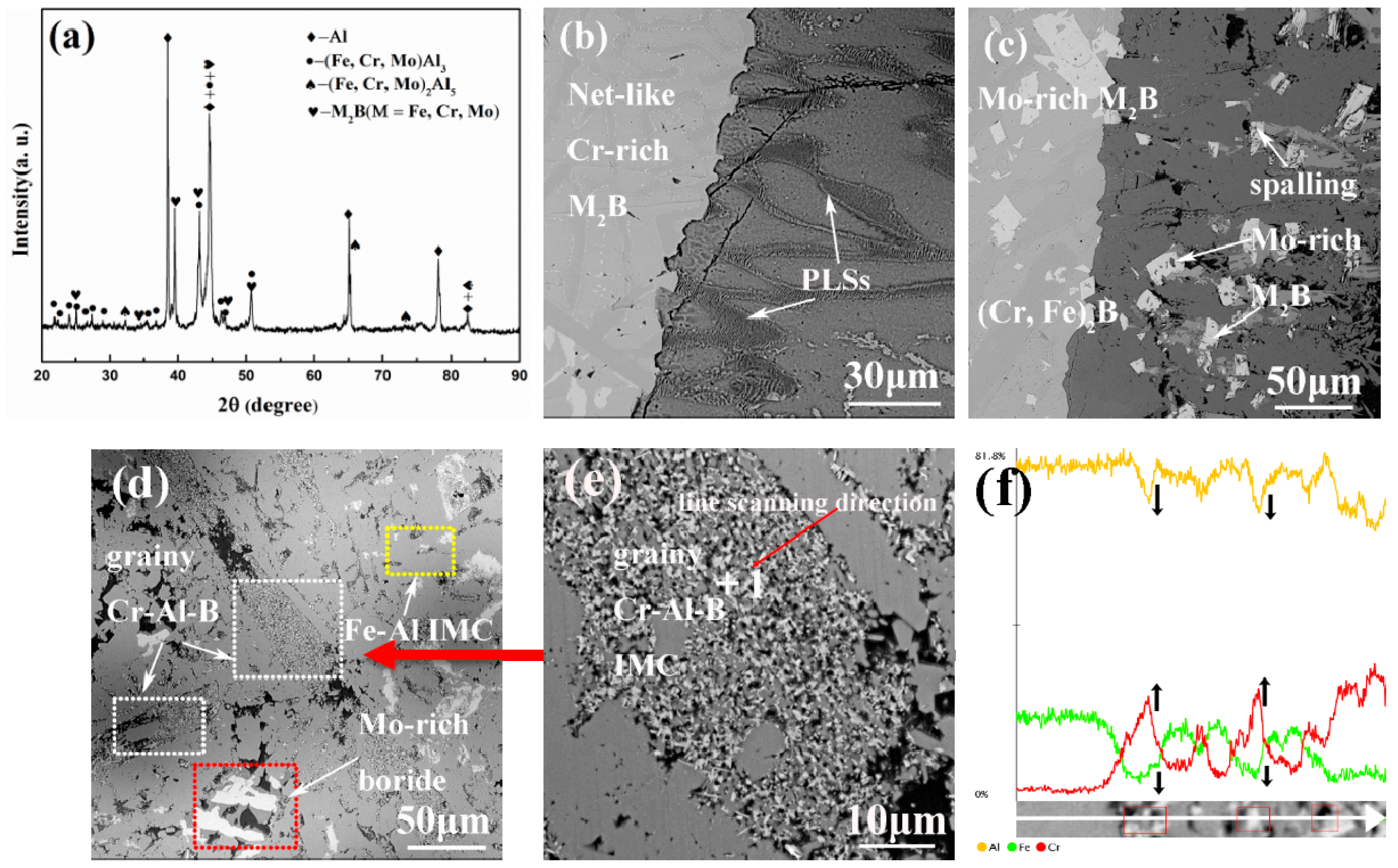
3.1. As-Cast Microstructure
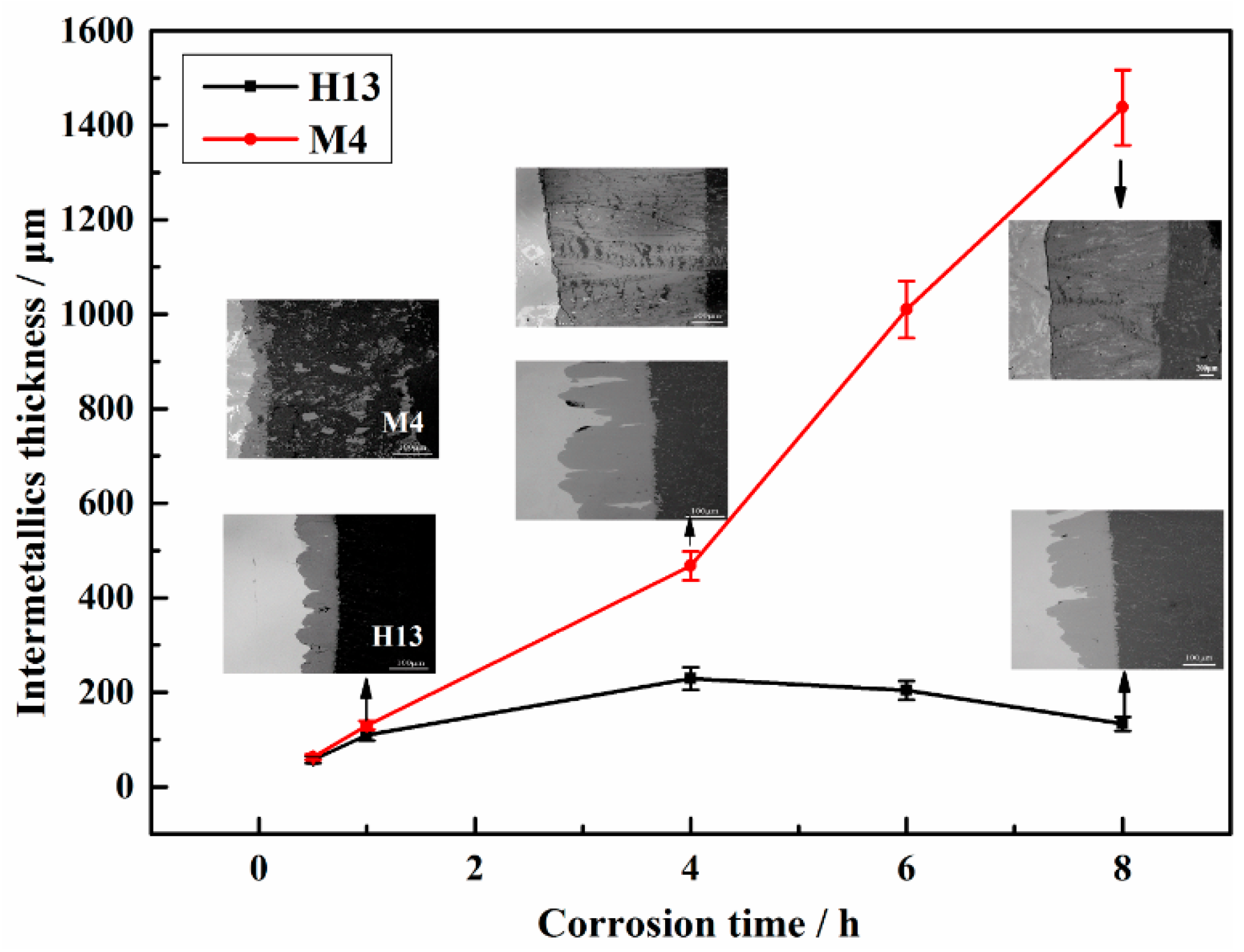
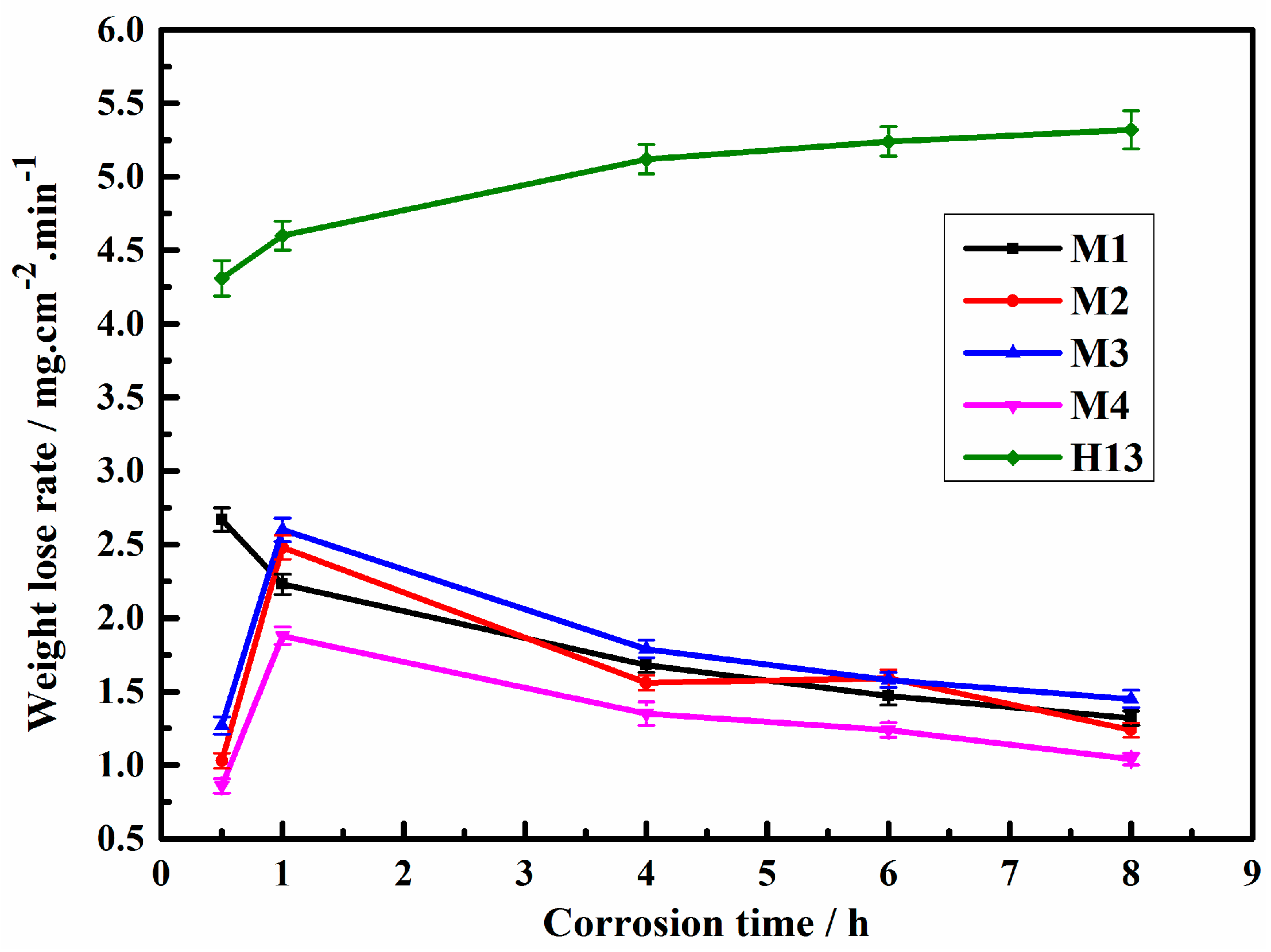
3.2. Corrosion Resistance
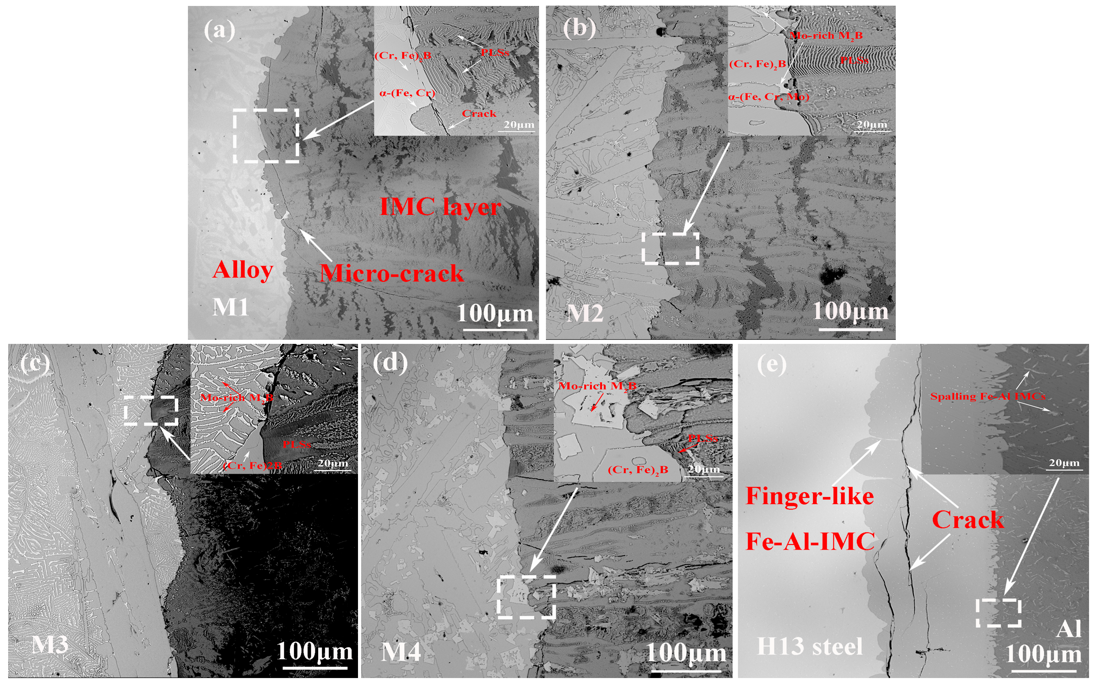
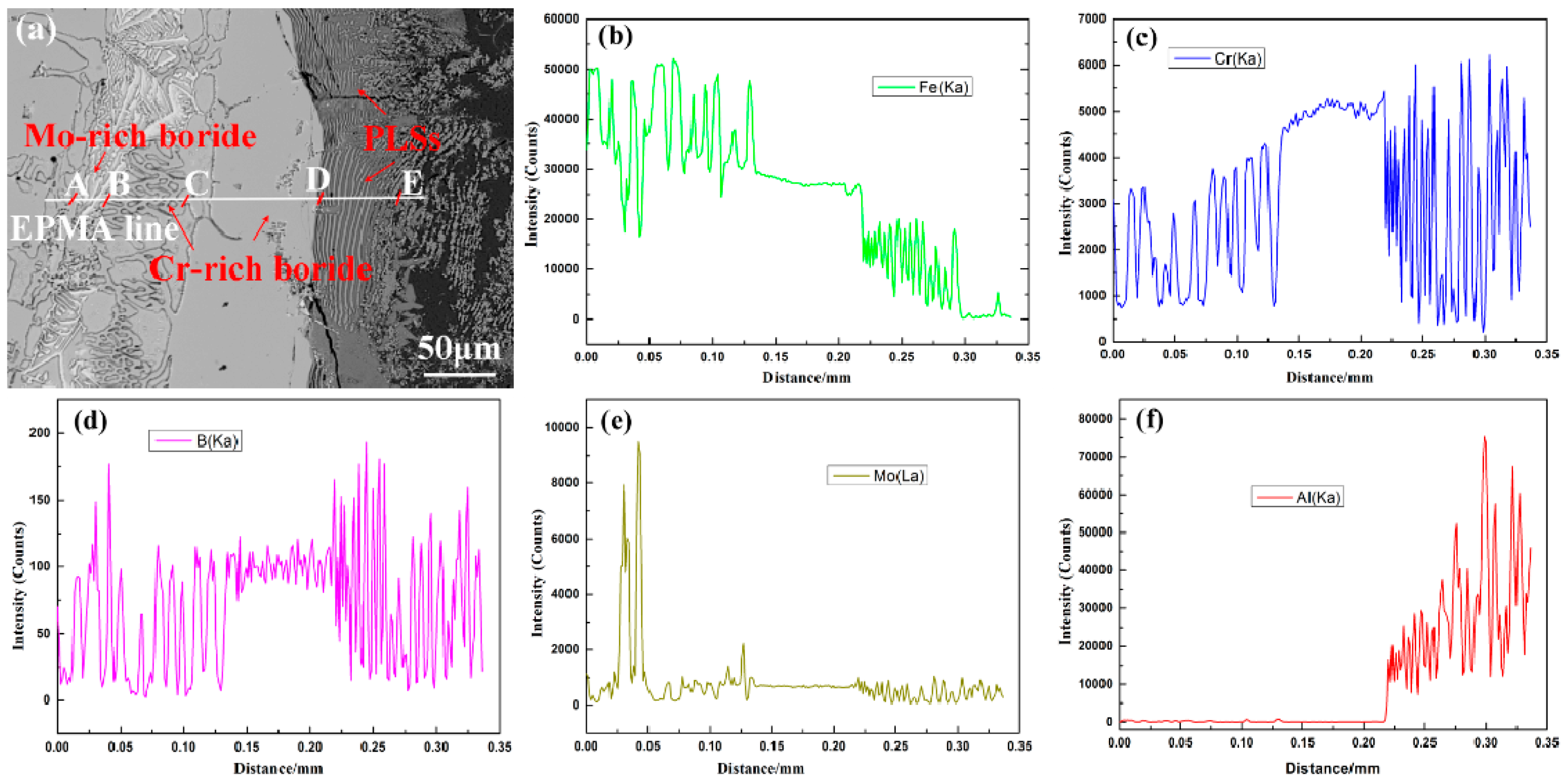
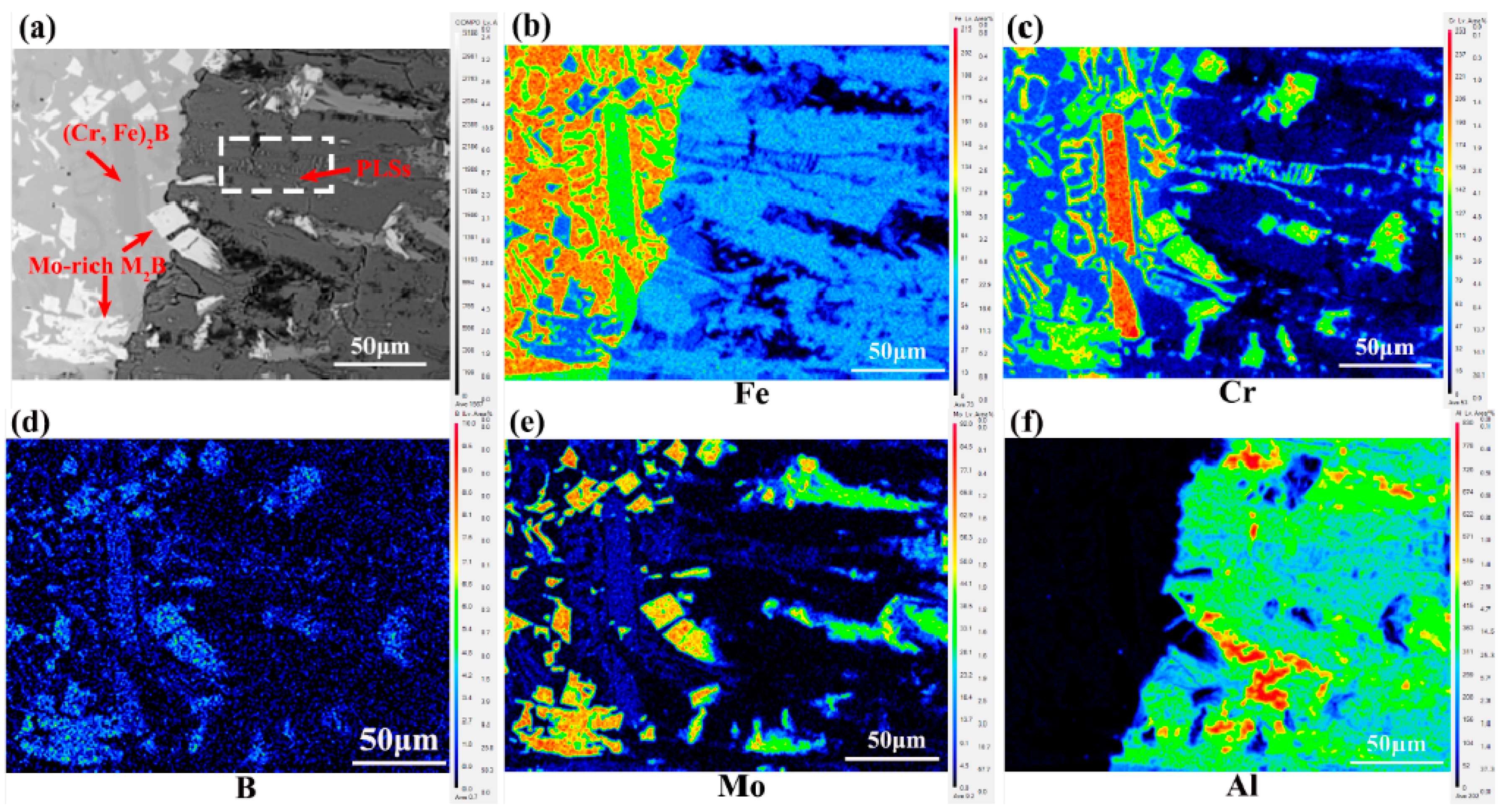
3.3. Cross-Sectional Morphology of the Interfacial Corrosion Layer
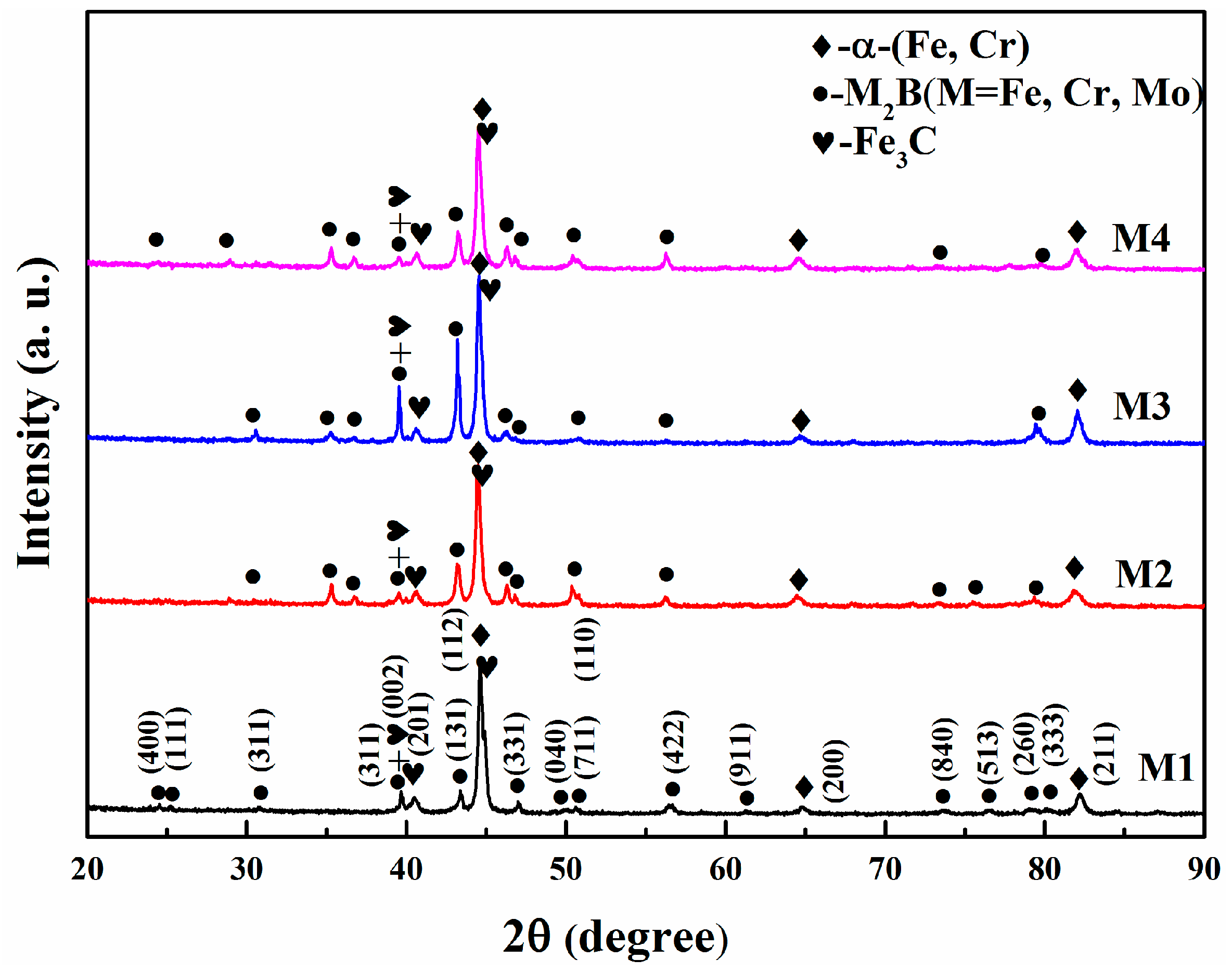
3.4. Corrosion Products
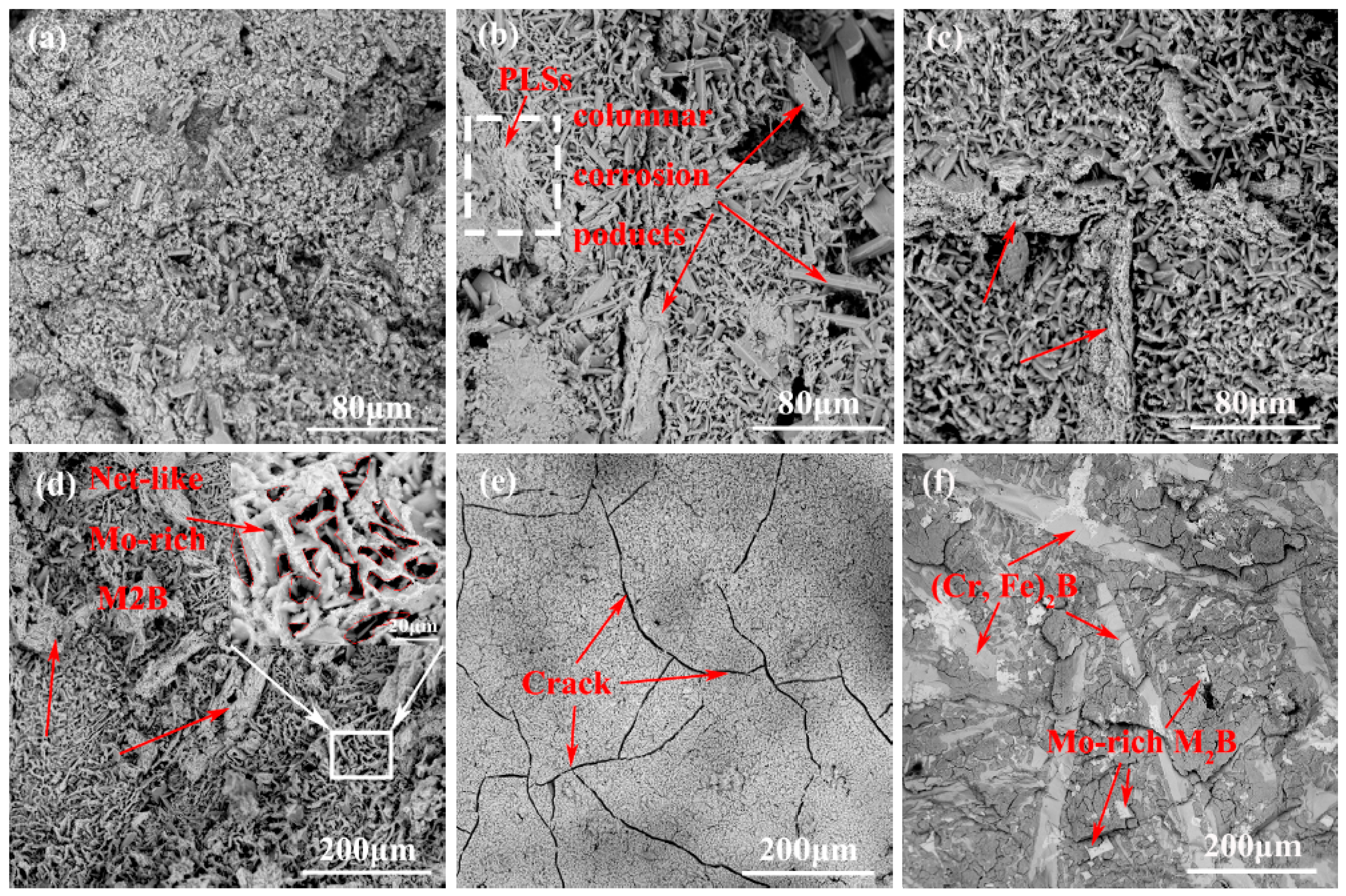
3.5. Corroded Surface
4. Conclusions
- (1)
- Mo addition plays an important role in the morphology of M2B-type borides. The microstructures of Mo-rich M2B borides change from a local net-like eutectic structure to a typical coarse dendritic structure and appear a kind blocky hypereutectic structure with the increase of Mo content.
- (2)
- The corrosion resistance of the M4 sample with an 8.3 wt.% Mo content is 3.8 times higher than that of H13 immersed in molten aluminum due to its blocky Mo-rich M2B boride and rod-like (Cr, Fe)2B.
- (3)
- The various M2B-type borides phases result in a synergistic effect that retards the corrosion of molten aluminum and presents a much slower corrosion rate than the matrix.
- (4)
- The Mo-rich M2B boride, rod-like (Cr, Fe)2B and its corrosion products of PLSs can act as roots to capture the Fe-Al IMCs and to prevent them from spalling off.
Author Contributions
Funding
Acknowledgments
Conflicts of Interest
References
- Balloy, D.; Tissier, J.C.; Giorgi, M.L.; Briant, M. Corrosion mechanisms of steel and cast iron by molten aluminum. Metall. Mater. Trans. A 2010, 41, 2366–2376. [Google Scholar] [CrossRef]
- Wang, D.; Shi, Z.; Zou, L. A liquid aluminum corrosion resistance surface on steel substrate. Appl. Surf. Sci. 2003, 214, 304–311. [Google Scholar]
- Shankar, S.; Apelian, D. Die soldering: Mechanism of the interface reaction between molten aluminum alloy and tool steel. Metall. Mater. Trans. B 2002, 33, 465–476. [Google Scholar] [CrossRef]
- Song, J.; Wang, X.; DenOuden, T.; Han, Q. Evolution of intermetallic phases in soldering of the die casting of aluminum alloys. Metall. Mater. Trans. A 2016, 47, 2609–2615. [Google Scholar] [CrossRef]
- Li, Y.; Tang, N.; Tunthawiroon, P.; Koizumi, Y.; Chiba, A. Characterisation of oxide films formed on Co–29Cr–6Mo alloy used in die-casting moulds for aluminium. Corros. Sci. 2013, 73, 72–79. [Google Scholar] [CrossRef]
- López, A.J.; Rams, J. Protection of carbon steel against molten aluminum attack and high temperature corrosion using high velocity oxygen-fuel WC–Co coatings. Surf. Coat. Technol. 2015, 262, 123–133. [Google Scholar] [CrossRef]
- Tunthawiroon, P.; Li, Y.; Tang, N.; Chiba, A. Enhancement of corrosion resistance of Fe–Cr–Mo alloy to molten Al by thermal oxidation in air. Corros. Sci. 2013, 77, 97–102. [Google Scholar] [CrossRef]
- Zhang, X.; Chen, W.; Luo, H.; Li, S.; Zhou, T.; Shi, L. Corrosion resistance and interfacial morphologies of novel Fe-Cr-Mo-B cast steels in molten aluminum. Corros. Sci. 2017, 125, 20–28. [Google Scholar] [CrossRef]
- Shahverdi, H.R.; Ghomashchi, M.R.; Shabestari, S.; Hejazi, J. Kinetics of interfacial reaction between solid iron and molten aluminium. J. Mater. Sci. 2002, 37, 1061–1066. [Google Scholar] [CrossRef]
- Bouayad, A.; Gerometta, C.; Belkebir, A.; Ambari, A. Kinetic interactions between solid iron and molten aluminium. Mater. Sci. Eng. A 2003, 363, 53–61. [Google Scholar] [CrossRef]
- Tanaka, Y.; Kajihara, M. Kinetics of isothermal reactive diffusion between solid Fe and liquid Al. J. Mater. Sci. 2010, 45, 5676–5684. [Google Scholar] [CrossRef]
- Bouche, K.; Barbier, F.; Coulet, A. Intermetallic compound layer growth between solid iron and molten aluminium. Mater. Sci. Eng. A 1998, 249, 167–175. [Google Scholar] [CrossRef]
- Rezaei, H.; Akbarpour, M.R.; Shahverdi, H.R. Effects of Interfacial Layers Fracture on the Dissolution Mechanism of Solid Fe in Liquid Al. JOM 2015, 67, 1443–1450. [Google Scholar] [CrossRef]
- Bobzin, K.; Brögelmann, T.; Brugnara, R.H.; Kruppe, N.C. CrN/AlN and CrN/AlN/Al2O3 coatings deposited by pulsed cathodic arc for aluminum die casting applications. Surf. Coat. Technol. 2015, 284, 222–229. [Google Scholar] [CrossRef]
- Khan, F.F.; Bae, G.; Kang, K.; Kumar, S.; Jeong, T.; Lee, C. Development of cermet coatings by kinetic spray technology for the application of die-soldering and erosion resistance. Surf. Coat. Technol. 2009, 204, 345–352. [Google Scholar] [CrossRef]
- Wang, D.; Shi, Z. Aluminizing and oxidation treatment of 1Cr18Ni9 stainless steel. Appl. Surf. Sci. 2004, 227, 255–260. [Google Scholar] [CrossRef]
- Chang, S.H.; Lin, Y.K.; Huang, K.T. Study on the thermal erosion, wear and corrosion behaviors of TiAlN/oxynitriding duplex-treated AISI H13 alloy steel. Surf. Coat. Technol. 2012, 207, 571–578. [Google Scholar] [CrossRef]
- Wang, Y.; Xing, J.; Ma, S.; Liu, G.; He, Y.; Yang, D.; Bai, Y. Effect of Fe2B orientation on erosion–corrosion behavior of Fe–3.5 wt.% B steel in flowing zinc. Corros. Sci. 2015, 98, 240–248. [Google Scholar] [CrossRef]
- Ma, S.; Xing, J.; Fu, H.; Yi, D.; Zhi, X.; Li, Y. Effects of boron concentration on the corrosion resistance of Fe–B alloys immersed in 460 C molten zinc bath. Surf. Coat. Technol. 2010, 204, 2208–2214. [Google Scholar] [CrossRef]
- Tsipas, D.N.; Triantafyllidis, G.K.; Kiplagat, J.K.; Psillaki, P. Degradation behaviour of boronized carbon and high alloy steels in molten aluminium and zinc. Mater. Lett. 1998, 37, 128–131. [Google Scholar] [CrossRef]
- Jian, Y.; Huang, Z.; Xing, J.; Wang, B. Effects of chromium addition on fracture toughness and hardness of oriented bulk Fe2B crystals. Mater. Charact. 2015, 110, 138–144. [Google Scholar] [CrossRef]
- Huang, Z.; Xing, J.; Guo, C. Improving fracture toughness and hardness of Fe2B in high boron white cast iron by chromium addition. Mater. Des. 2010, 31, 3084–3089. [Google Scholar] [CrossRef]
- Liu, Y.; Li, B.; Li, J.; He, L.; Gao, S.; Nieh, T.G. Effect of titanium on the ductilization of Fe–B alloys with high boron content. Mater. Lett. 2010, 64, 1299–1301. [Google Scholar] [CrossRef]
- Fu, H.; Xiao, Q.; Kuang, J.; Jiang, Z.; Xing, J.D. Effect of rare earth and titanium additions on the microstructures and properties of low carbon Fe–B cast steel. Mater. Sci. Eng. A 2007, 466, 160–165. [Google Scholar] [CrossRef]
- Huang, Z.; Xing, J.; Lv, L. Effect of tungsten addition on the toughness and hardness of Fe2B in wear-resistant Fe–B–C cast alloy. Mater. Charact. 2013, 75, 63–68. [Google Scholar] [CrossRef]
- Han, F.; Hwang, B.; Suh, D.W.; Wang, Z.; Lee, D.L.; Kim, S.J. Effect of molybdenum and chromium on hardenability of low-carbon boron-added steels. Met. Mater. Int. 2008, 14, 667. [Google Scholar] [CrossRef]
- Tunca, N.; Delamore, G.W.; Smith, R.W. Corrosion of Mo, Nb, Cr, and Y in molten aluminum. Metall. Trans. A 1990, 21, 2919–2928. [Google Scholar] [CrossRef]
- Takahashi, J.; Ishikawa, K.; Kawakami, K.; Fujioka, M.; Kubota, N. Atomic-scale study on segregation behavior at austenite grain boundaries in boron-and molybdenum-added steels. Acta Mater. 2017, 133, 41–54. [Google Scholar] [CrossRef]
- Ma, S.; Xing, J.; Fu, H.; Gao, Y.; Zhang, J. Microstructure and crystallography of borides and secondary precipitation in 18 wt.% Cr–4 wt.% Ni–1 wt.% Mo–3.5 wt.% B–0.27 wt.% C steel. Acta Mater. 2012, 60, 831–843. [Google Scholar] [CrossRef]
- Röttger, A.; Lentz, J.; Theisen, W. Boron-alloyed Fe–Cr–C–B tool steels—Thermodynamic calculations and experimental validation. Mater. Des. 2015, 88, 420–429. [Google Scholar] [CrossRef]
- Jahazi, M.; Jonas, J.J. The non-equilibrium segregation of boron on original and moving austenite grain boundaries. Mater. Sci. Eng. A 2002, 335, 49–61. [Google Scholar] [CrossRef]
- Faulkner, R.G. Non-equilibrium grain-boundary segregation in austenitic alloys. J. Mater. Sci. 1981, 16, 373–383. [Google Scholar] [CrossRef]
- Christodoulou, P.; Calos, N. A step towards designing Fe–Cr–B–C cast alloys. Mater. Sci. Eng. A 2001, 301, 103–117. [Google Scholar] [CrossRef]
- Zhang, X.; Chen, W.; Luo, H.; Zhou, T. Formation of periodic layered structure between novel Fe-Cr-B cast steel and molten aluminum. Scr. Mater. 2017, 130, 288–291. [Google Scholar] [CrossRef]
- Ma, S.; Xing, J.; Fu, H.; He, Y.; Bai, Y.; Li, Y.; Bai, Y. Interface characteristics and corrosion behaviour of oriented bulk Fe2B alloy in liquid zinc. Corros. Sci. 2014, 78, 71–80. [Google Scholar] [CrossRef]
- Ma, S.; Xing, J.; Fu, H.; Yi, D.; Li, Y.; Zhang, J.; Zhu, B.; Gao, Y. Microstructure and interface characteristics of Fe–B alloy in liquid 0.25 wt.% Al–Zn at various bath temperatures. Mater. Chem. Phys. 2012, 132, 977–986. [Google Scholar] [CrossRef]
- Miller, A.E.; Maijer, D.M. Investigation of erosive-corrosive wear in the low pressure die casting of aluminum A356. Mater. Sci. Eng. A 2006, 435, 100–111. [Google Scholar] [CrossRef]
- Zhang, X.; Li, X.; Chen, W. Interfacial reactions of duplex stainless steels with molten aluminum. Surf. Interface Anal. 2015, 47, 648–656. [Google Scholar] [CrossRef]
- Huang, Z.; Xing, J.; Tao, X. Effect of molybdenum addition on fracture toughness and hardness of Fe2B in Fe–B–C cast alloy. Int. J. Mater. Res. 2012, 103, 1539–1543. [Google Scholar] [CrossRef]
- Campbell, C.E.; Kattner, U.R. Assessment of the Cr-B system and extrapolation to the Ni-Al-Cr-B quaternary system. Calphad 2002, 26, 477–490. [Google Scholar] [CrossRef]
- Abdelkader, H.S.; Faraoun, H.I. Ab initio investigation of Al/MoB interfacial adhesion. Comput. Mater. Sci. 2011, 50, 880–885. [Google Scholar] [CrossRef]
- Dybkov, V.I. Interaction of 18Cr-10Ni stainless steel with liquid aluminium. J. Mater. Sci. 1990, 25, 3615–3633. [Google Scholar] [CrossRef]
- Liu, X.; Barbero, E.; Xu, J.; Burris, M.; Chang, K.M.; Sikka, V. Liquid metal corrosion of 316L, Fe3Al, and FeCrSi in molten Zn-Al baths. Metall. Mater. Trans. A 2005, 36, 2049–2058. [Google Scholar] [CrossRef]


| Elements | C | B | Cr | Mo | Si | Al | Mn | Cu | V | Fe |
|---|---|---|---|---|---|---|---|---|---|---|
| M1 | 0.25 | 3.68 | 13.54 | 0 | 0.73 | 0.44 | 0.32 | 0.13 | 0.07 | Bal. |
| M2 | 0.26 | 3.42 | 14.73 | 3.22 | 0.98 | 0.79 | 0.31 | 0.17 | 0.05 | Bal. |
| M3 | 0.26 | 3.12 | 15.28 | 6.19 | 1.13 | 0.97 | 0.32 | 0.25 | 0.10 | Bal. |
| M4 | 0.28 | 3.19 | 16.35 | 8.30 | 1.21 | 0.85 | 0.34 | 0.24 | 0.07 | Bal. |
| H13 | 0.38 | - | 5.30 | 1.30 | 1.00 | - | 0.40 | - | 0.90 | Bal. |
| Number | Fe | Cr | B | Mo | Calculated Formula |
|---|---|---|---|---|---|
| 1 | 37.36 ± 1.41 | 29.38 ± 0.34 | 33.26 ± 1.80 | 0 | Fe1.12Cr0.88B |
| 2 | 44.55 ± 1.24 | 22.29 ± 1.23 | 33.16 ± 2.40 | 0 | Fe1.34Cr0.68B |
| 3 | 27.81 ± 0.95 | 19.16 ± 0.85 | 34.74 ± 0.96 | 18.29 ± 0.78 | Fe0.80Cr0.55Mo0.53B |
| 4 | 25.26 ± 1.05 | 19.79 ± 0.94 | 30.94 ± 1.50 | 24.01 ± 1.30 | Fe0.82Cr0.64Mo0.78B |
| 5 | 21.84 ± 0.80 | 17.36 ± 0.28 | 37.11 ± 1.25 | 23.69 ± 1.45 | Fe0.59Cr0.47Mo0.64B |
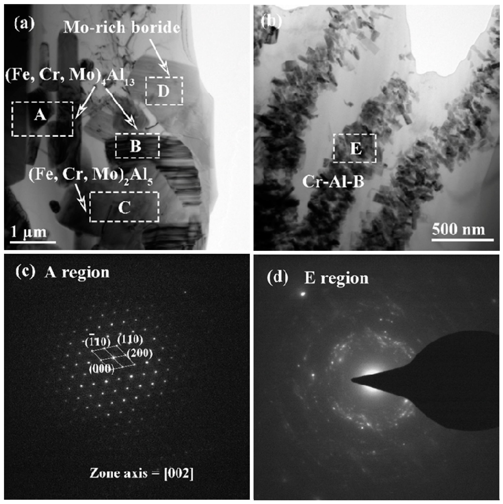
| Regions | Fe | Cr | B | Mo | Al | Phases |
|---|---|---|---|---|---|---|
| A | 23.15 | 1.08 | 0 | 0.23 | 75.54 | (Fe, Cr, Mo)4Al13 |
| B | 19.77 | 1.94 | 10.26 | 0.21 | 67.82 | (Fe, Cr, Mo)4Al13 |
| C | 25.19 | 2.07 | 0 | 0.43 | 72.31 | (Fe, Cr, Mo)2Al5 |
| D | 18.30 | 15.32 | 43.62 | 21.64 | 1.12 | Mo-rich boride |
| E | 1.24 | 22.33 | 21.08 | 0 | 55.32 | Cr-Al-B IMC |
© 2019 by the authors. Licensee MDPI, Basel, Switzerland. This article is an open access article distributed under the terms and conditions of the Creative Commons Attribution (CC BY) license (http://creativecommons.org/licenses/by/4.0/).
Share and Cite
Ling, Z.; Chen, W.; Xu, W.; Zhang, X.; Lu, T.; Liu, J. The Influence of A Mo Addition on the Interfacial Morphologies and Corrosion Resistances of Novel Fe-Cr-B Alloys Immersed in Molten Aluminum. Materials 2019, 12, 256. https://doi.org/10.3390/ma12020256
Ling Z, Chen W, Xu W, Zhang X, Lu T, Liu J. The Influence of A Mo Addition on the Interfacial Morphologies and Corrosion Resistances of Novel Fe-Cr-B Alloys Immersed in Molten Aluminum. Materials. 2019; 12(2):256. https://doi.org/10.3390/ma12020256
Chicago/Turabian StyleLing, Zicheng, Weiping Chen, Weiye Xu, Xianman Zhang, Tiwen Lu, and Jian Liu. 2019. "The Influence of A Mo Addition on the Interfacial Morphologies and Corrosion Resistances of Novel Fe-Cr-B Alloys Immersed in Molten Aluminum" Materials 12, no. 2: 256. https://doi.org/10.3390/ma12020256