Size-Dependent Phase Transformation during Gas Atomization Process of Cu–Sn Alloy Powders

1
State Key Laboratory of Advanced Welding and Joining, School of Materials Science and Engineering, Harbin Institute of Technology at Shenzhen, Shenzhen 518055, China
2
Flexible Printed Electronic Technology Center, Harbin Institute of Technology at Shenzhen, Shenzhen 518055, China
*
Author to whom correspondence should be addressed.
Materials 2019, 12(2), 245; https://doi.org/10.3390/ma12020245
Submission received: 8 December 2018
/
Revised: 1 January 2019
/
Accepted: 8 January 2019
/
Published: 12 January 2019
(This article belongs to the Section Manufacturing Processes and Systems)
Abstract
:For binary element atomization, it is essential to investigate the phase transformation from liquid to solid as a functions of the droplet sizes, as well as the reaction competitiveness, during gas atomizing solidification of their nuclei. In the present work, a series of phase transformations of undercooled Cu (60.9 wt.%)/Sn droplets were analyzed when atomized by pressure gas. The results indicated that the microstructures of the obtained powders and their morphologies were highly relevant to the droplet size. According to the phase characteristics analyzed by the microstructural observations in combination with the transient nucleation theory, powders with sizes from 10 to 100 μm were divided into three categories, exhibiting lotus-leaf, island, and stripe morphologies. The competitive formation of Cu6Sn5 or Cu3Sn was also controlled by the droplet sizes, and a diameter of approximately 45 μm was identified as the threshold size. After heat treatment at 300 °C for 4 h, the powders consisted of a single η’ Cu6Sn5 phase. The obtained Cu6Sn5 phase powders can be used in the field of high-temperature applications as intermetallic balls for integrated chip interconnects.
1. Introduction
With the development of powder metallurgy technology, the performance of bulk material was greatly improved by the extensive use of micro and nano powder synthesizing, which stimulates the industrial market demand for powders [1,2,3,4]. The development of powder injection molding in particular further opens the extensive application of powders (e.g., titanium, aluminum, nickel, and steel-based alloy powders) in the fields of aerospace, shipbuilding, automobile, and powder generation industries [5,6]. The metallic parts produced with these powders have advanced properties which differ from those of conventional materials, such as excellent mechanical properties, special magnetic properties, high electrical conductivity and diffusivity, reaction reactivity, and catalytic activity. Studies also reported that highly filled powders can be used in paper-coating processes [7,8]. However, for powders consisting of several elements, their phases and elemental distributions are difficult to control during their formation, which leads to significant impacts on the microstructure and properties of the products produced by additive manufacturing.
Many studies focused on the preparation of micro and nano powders [9,10,11,12,13]. A variety of methods can be applied for powder preparation, but the production process is mainly divided into two categories based on the substantive analysis: mechanical and physical chemistry methods, such as ball milling [9,10], liquid reduction methods [11,12], and atomization [13]. Ball milling takes a long time, and the ball may cause rising temperature due to the impact effect of the grinding, which triggers the metal alloying. Moreover, it is difficult to control the morphology of spherical powders. The reaction of the liquid reduction method affiliates with the chemical reduction reaction and is difficult to control due to the fast reaction rate. In addition, the content of impurities in the powder is too high to purify and the challenge of poor agglomeration of the powders still remains unsolved. It is worth mentioning that gas atomization is a process of pulverizing a liquid metal or alloy stream into small droplets with high-speed airflow before coagulating them into powders. Using the aerosolization method, the droplets are solidified at a higher cooling rate compared to the mechanical method and chemical reduction method, and the atomized powder is spherical and has low oxygen content, which is suitable for the preparation of various kinds of metal and alloy powders.
The prominent advantages of gas atomization already attract much attention. Previously, the aerosol preparation and the application of alloy powders were studied comprehensively. High-efficiency catalyst Al–Ni powders were synthesized via aerosolization [14]. Using gas atomization together with hydrogen annealing, an Ni metal hydride battery AB5 alloy could work at low temperature [15]. The electrochemical corrosion behavior of Al–Ni alloy powders was investigated using aerosol spraying [16]. There are also researchers who modeled the process of aerosolization and then measured and controlled the parameters, effectively optimizing the process of aerosolization [17,18]. The microstructure and the phase distribution of the powders were also analyzed extensively. Wang et al. [19] obtained immiscible alloy powders with an egg-type microstructure. Using plasma rotating electrode processing, Guo et al. [20] found that the main phases of Nb–Si-based alloy powders were Nb sosoloid, β-Nb5Si3, and Nb3Si. A fine lamellar eutectic structure was formed in the interior powder during solidification. The phase transformation of the undercooled Ti–48Al (at.%) droplets via gas atomization was also investigated and discussed regarding the primary phases α and β [21].
Though gas atomization is highly regarded, the phase compositions and morphologies as a function of powder size are yet to be addressed systematically. For gas atomization powders with different sizes, the microstructure and the phase composition may be different because of the different solidification conditions. The microstructure evolution of the powders during the gas atomization process also varies. More importantly, an in-depth comprehension of the microstructure evolution during the gas atomization process is critical for controlling the phase composition and surface morphology of the powders, which could promote their potential application in different fields. Therefore, in this paper, we report an approach to the formation of the Cu (60.9 wt.%)/Sn powders using the gas atomization process to control the morphology, microstructural evolution, and phase composition. In particular, the formation mechanism based on powder size is illustrated systematically. Furthermore, the high-temperature applications of atomized powders for chip attachment after heat treatment were also addressed.
2. Materials and Methods
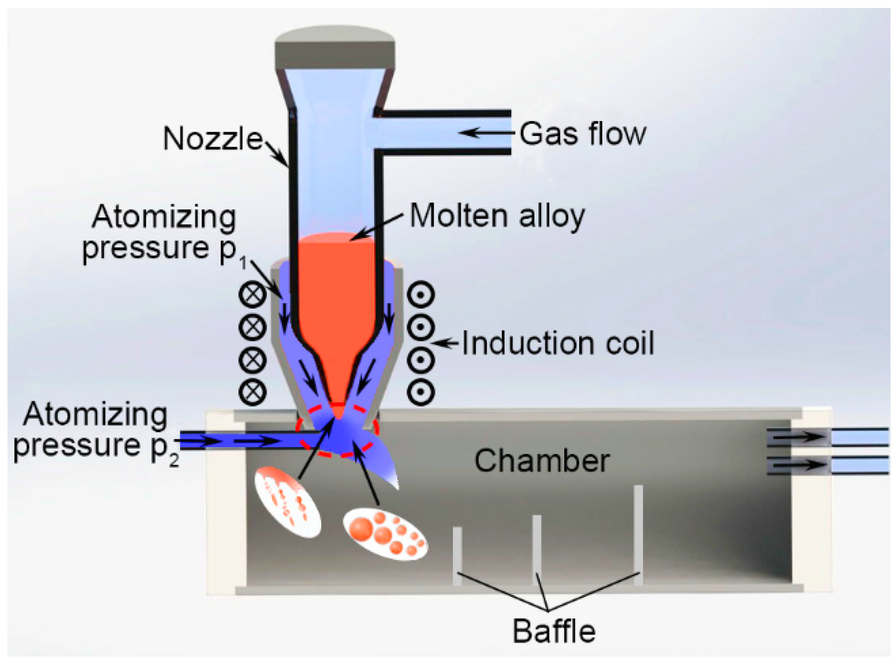
A self-designed gas atomizer consisting of a quartz crucible and an atomizing die is shown in Figure 1. The atomizing nozzle is a conical muzzle with an inclined angle of 80° and an outlet diameter of 1.5 mm. Firstly, with a nominal composition of Cu:Sn = 6:5 (at.%), the copper-based alloy was prepared using induction melting of Cu and Sn bars three times in a quartz device with a protective gas in order to achieve a homogeneous composition. Then, the ingot alloy was cut to the appropriate size (1 cm × 1 cm × 2 cm) and heated afterward in the nozzle over its melting point via induction heating after removing the oxide film on the surface of the alloy. The molten alloy was protected by inert gas with slight gas flow at first. After heating for approximately 8 s, the ingot alloy melted, and the gas flow was suddenly increased from 0.15 m3/h to 0.5 m3/h. The molten alloy stream with the temperature of 600 to 700 °C was removed from the nozzle outlet and atomized using an auxiliary atomization pressure, P1, and the dominating atomization pressure, P2 (2.3 MPa), through the corundum tube. The kinetic energy transferred from the high velocity of jet-gas to the melt stream caused fragmentation into a variety of shapes down to sub-micrometer sizes, such as flakes, ellipsoids, ligaments, and droplets [22,23]. A series of powders were super-cooled during flying and collected between different baffles. Three different groups of powders ranging from 10 μm to 100 μm in diameter were further classified using standard sieves, whose meshes were 150, 200, 325, and 1800, and then corroded by 10% hydrochloric acid/ethanol solution for 24 h. Finally, powders with different diameters, 74 μm–100 μm, 43 μm–74 μm, and 10 μm–43 μm, were subjected to heat treatment at a temperature of 300 °C for 4 h in an atmosphere of inert gas and then cooled down to the ambient temperature in the furnace to obtain the single Cu6Sn5 powder.
Phase compositions of the Cu–Sn binary powders with or without thermal treatment were identified by X-ray diffraction (XRD, D/max-2500/PC, Cu Kα, Rigaku, Tokyo, Japan) and differential scanning calorimetry (DSC, STA-449F3, Netzsch, Selb, Germany), together with differential thermal analysis (DTA, STA-449F3, Netzsch, Selb, Germany) testing, under the protection of argon with a heating speed of 10 °C/s and temperature ranging from room temperature to 800 °C. Distribution of different phases as a function of powder size with or without corrosion by 15% hydrochloric acid/ethanol solution was examined using a scanning electron microscope (SEM, S-4700, Hitachi, Tokyo, Japan) equipped with an energy dispersive X-ray spectrometer (EDS, PV7746/40-ME, EDAX, Mahwah, NJ, USA) detector. To observe the interior microstructures of the Cu–Sn binary powders without any treatment, they were mounted in epoxy, polished, and then etched with 10% hydrochloric acid/ethanol solution for 15 s.
3. Results and Discussion
3.1. Powder Size Distribution and Microstructure Characterization
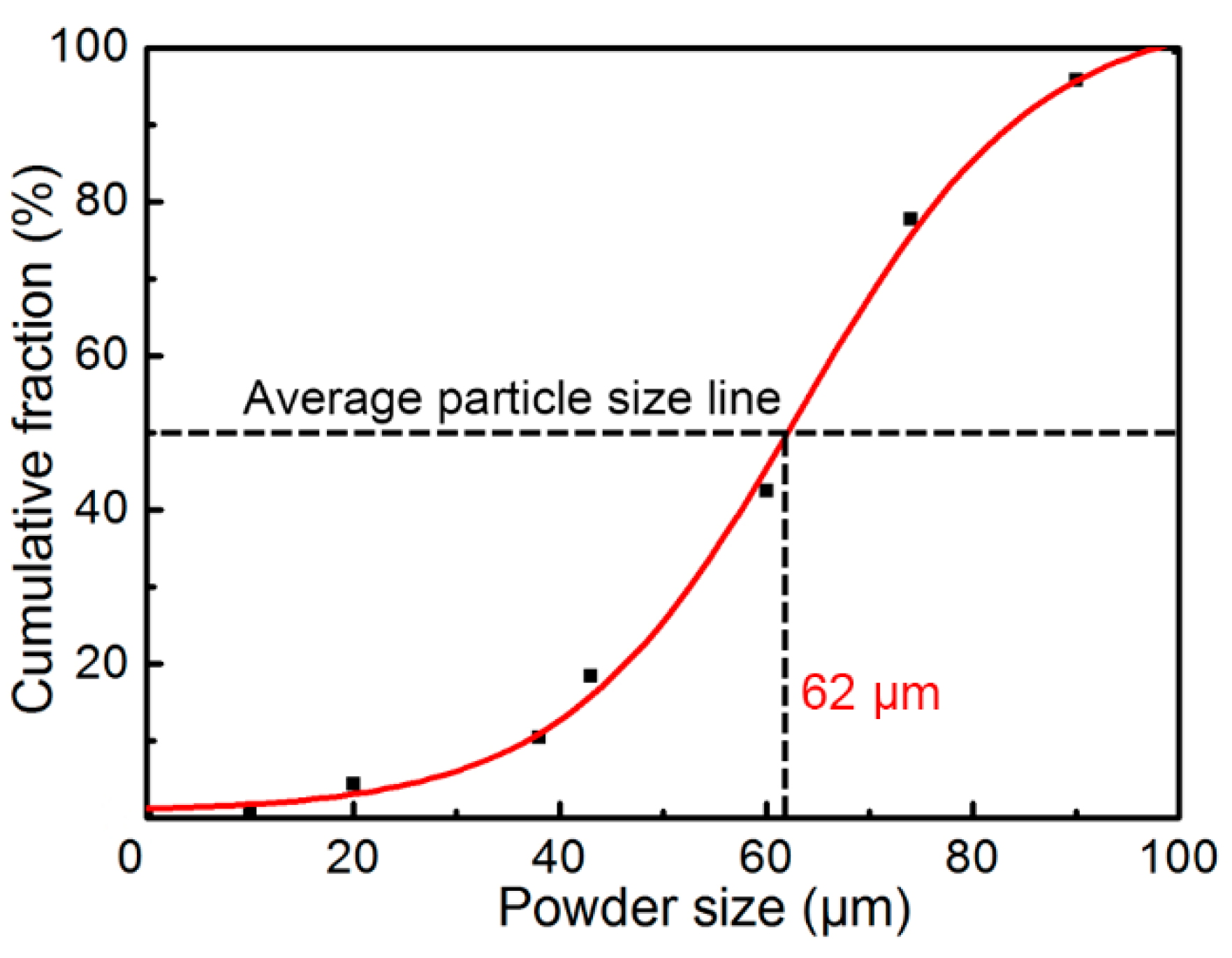
Figure 2 illustrates the cumulative proportion of various sizes of powders. The black dots in the graph represent the true mass fraction measured with the analytical balance after screening with standard sieves whose meshes were 150, 180, 200, 250, 325, 400, 900, and 1800, and the curve was fitted using by the DoseResp function. When the cumulative mass proportion was 50%, the corresponding particle diameter was 62 μm, which is basically the same as the spherical diameter predicted by the equation of Seki et al. [24], since the calculated average particle size was about 65 μm.
where D is the average powder size (μm) and P is the gas pressure (MPa).
D = 68P−0.056
Figure 3a demonstrates the XRD profile of the obtained powders of different sizes, and the phases mainly consisted of Cu6Sn5, Cu3Sn, and Sn phases, regardless of size. Figure 3b illustrates the DSC profiles of the same weight (0.1 g) of pre-atomized powders with different diameters from 100 °C to 700 °C. When the temperature rose to about 185 °C, an obvious endothermic peak emerged (marked A), indicating the phase transformation from η’ Cu6Sn5 to η Cu6Sn5 [25]. The following endothermic peak of melting of Sn (marked B), melting of η Cu6Sn5 (marked C), and melting of Cu3Sn phases (marked D) further proved the existence of the identified phases by XRD. There was an obvious exothermic peak between C and D, indicating bits of the formation of the Cu3Sn phase during the heating process of DSC testing. In addition, it is worth noting that, compared to the smaller powders, the bigger ones showed the stronger Sn endothermic peak and weaker Cu6Sn5 and Cu3Sn endothermic peak, indicating that the smaller powders might consist of more Cu6Sn5 and Cu3Sn phases.
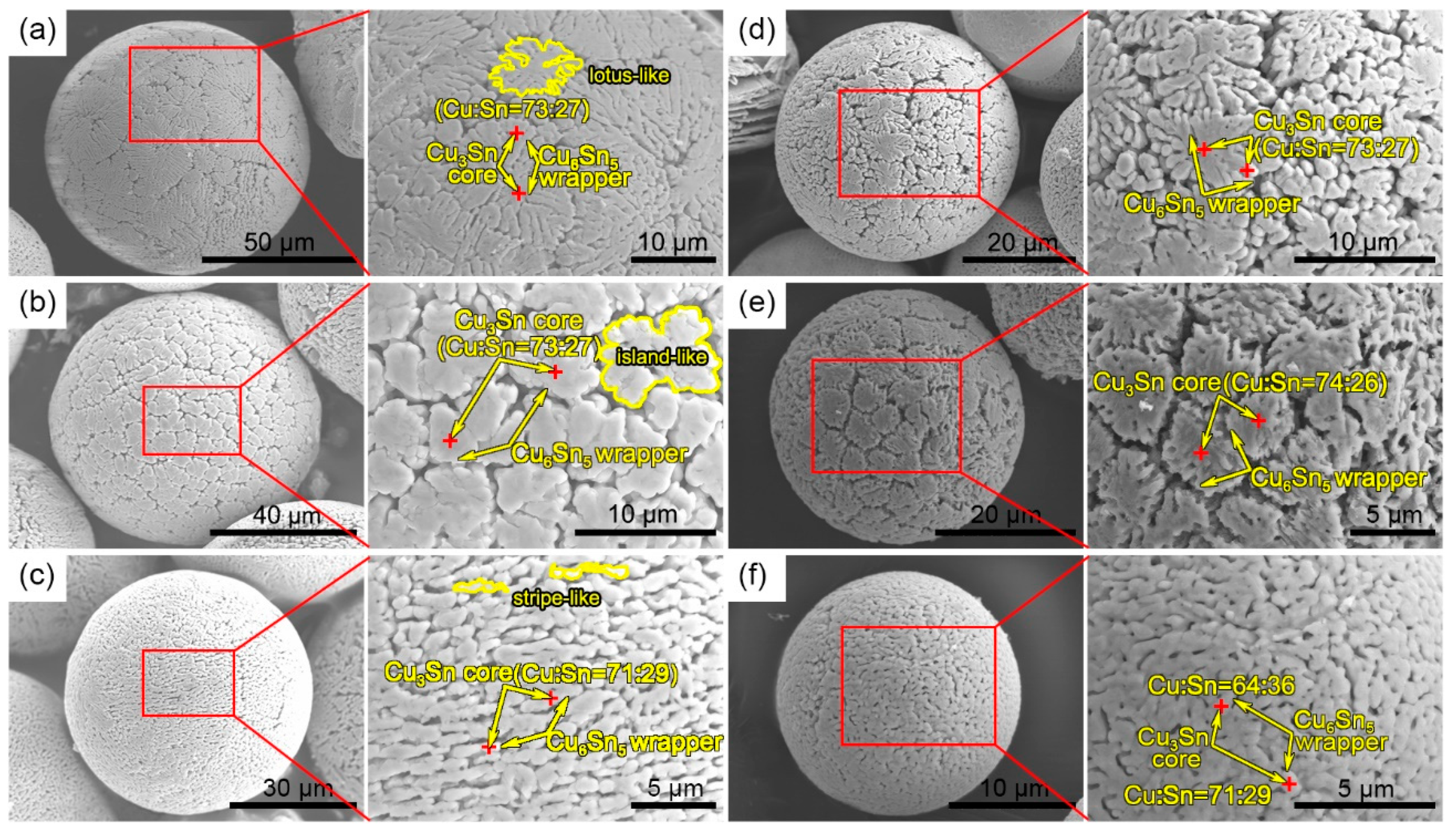
Figure 4 shows the surface morphology of the microstructure as a function of powder size after deep corrosion for 24 h. The Sn phase on the surface was completely corroded, and only intermetallic phases, such as Cu6Sn5 and Cu3Sn, were residual. In particular, surface morphological features were different between the powders with different diameters. The surface microstructure of the powder with a diameter of 84 μm (Figure 4a) exhibited the shape of a lotus leaf with size ranging from 5 μm to 40 μm. In Figure 4b, the diameter of the powder was 72 μm, whose surface was in an island shape. Some islands were combined to form larger ones. Their sizes ranged from 2 μm to 10 μm in diameter. When the particle size reached approximately 59 μm (Figure 4c), the surface was full of the entirely different stripe-like microstructures, whose sizes were about 0.5 μm in width and 1.5–2.5 μm in length. Especially notable was the fact that, when the particle sizes were down to 44 μm (Figure 4d), 36 μm (Figure 4e), and 19 μm (Figure 4f), the surface microstructures of the powders were in the shapes of a lotus leaf, island, and stripe, respectively, appearing as a reflection of the powders of 84-μm, 72-μm, and 59-μm sizes. Most EDS results of the powder with different diameter showed that the ratio of Cu to Sn was slightly smaller than 3:1 (the EDS results of this paper are the atomic ratio of Cu and Sn, and if the difference between values was less than 4%, the result took the average), indicating that most of the regions marked by a red cross were Cu3Sn and a bit of Cu6Sn5. The Cu3Sn core was wrapped with a minority of the Cu6Sn5, shell because the Cu3Sn precipitated before the Cu6Sn5 during solidification.
Figure 5 exhibits the interior morphology of the microstructure of the powders with different diameters after etching with hydrochloric acid/alcohol solution for 15 s. In Figure 5a, the interior of the powder with the diameter of 82 μm exhibited a clear branch-like microstructure and columnar crystals, separated by the Sn phase; the branch-like tissue may correspond to the cross-section of the Cu6Sn5 wrapper (the outer ring of lotus-like tissue in Figure 4a). Furthermore, the direction of the columnar crystals was generally the same, spanning from the surface to the center. The size of the columnar crystals was about 1.5–2.5 μm in width and 7–10 μm in length, indicating the cross-section of the lotus-like tissue in Figure 4a. In Figure 5b, the microstructure in the powders with the diameter of 70 μm was different from that in Figure 5a and had no feature of directional growth. Meanwhile, the size and the distribution of each island were uniform, similar to the isometric crystal. In Figure 5c, the interior stripe-like microstructure of the powder exhibited the feature of directional growth from the surface to the center and was relatively uniform in size. Similarly, the internal microstructures of the powders with diameters of 38 μm (Figure 5d), 34 μm (Figure 5e), and 22 μm (Figure 5f) were basically the same as those with sizes of 82 μm (Figure 5a), 70 μm (Figure 5b), and 59 μm (Figure 5c), respectively.
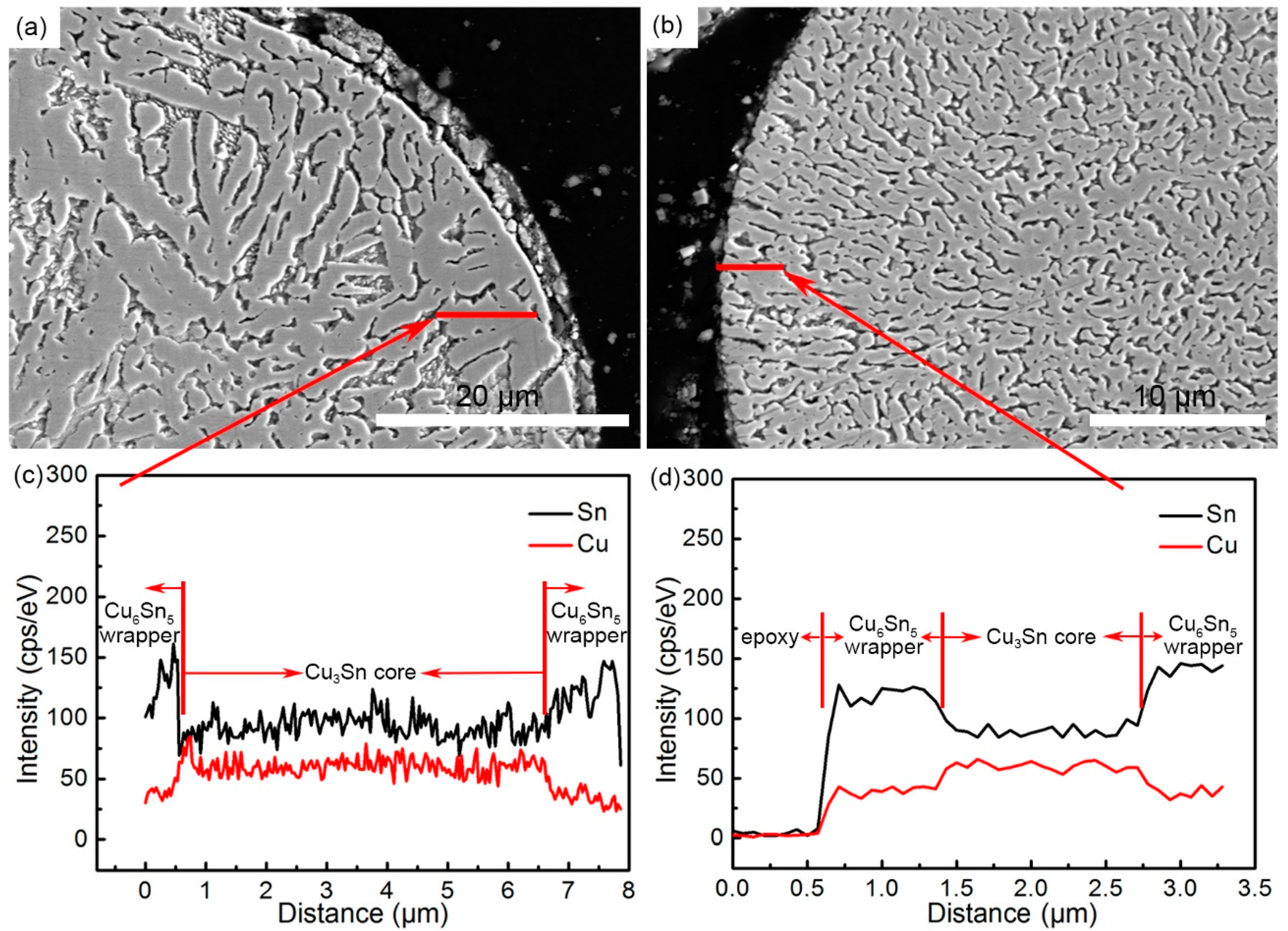
Figure 6 illustrates the EDS line-scanning results of the typical cross-sectional microstructures of the powders described in Figure 5a,c. The positions of the lines are shown in Figure 6a,b, and the corresponding line-scanning results are shown in Figure 6c,d. The energy spectrum values of Sn were higher on both sides of the curve, while the middle part was lower. In contrast, the energy spectrum values of Cu were higher in the middle part and lower on both sides (Figure 6c). Meanwhile, the condition in Figure 6d was consistent with that of Figure 6c (the spectrum values of Sn and Cu at the beginning of the curve were almost zero, which proved to be epoxy). Therefore, it indicated that both sides of the line were of the Cu6Sn5 phase, and the middle part was the Cu3Sn phase, which further confirmed the inference that Cu3Sn cores were surrounded by the outer Cu6Sn5 wrapper (Figure 4 and Figure 5).
3.2. Formation Mechanism of the Microstructure
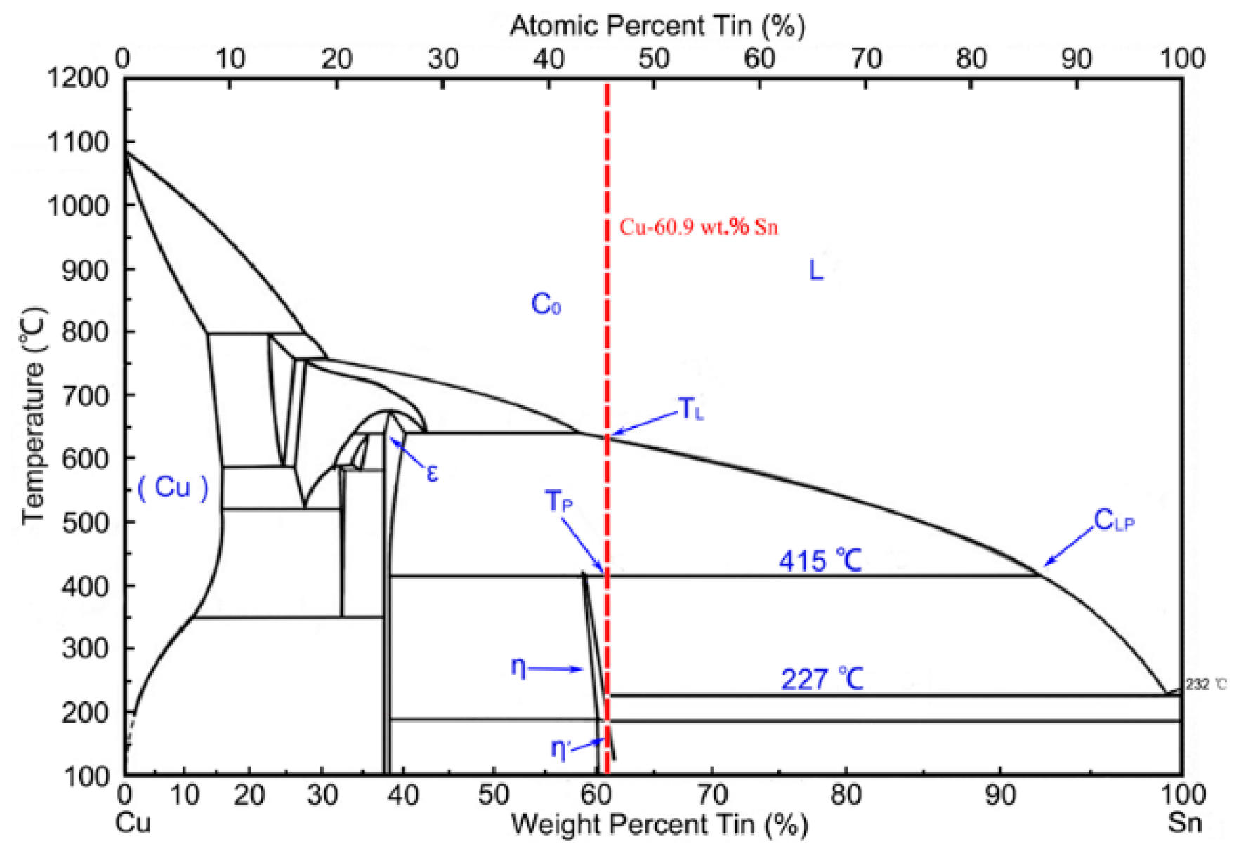
Figure 7 illuminates the equilibrium binary Cu–Sn phase diagram. The primary ε phase (Cu3Sn phase) firstly precipitated when the liquid melt (L) with a composition of Cu (60.9 wt.%)/Sn (C0) was cooled down to the liquidus temperature (TL). Then, the initial ε phase grew and continued to precipitate the newly formed ε phase. As the temperature dropped to the peritectic temperature (TP), the η phase (η Cu6Sn5) precipitated on the surface of the ε phase, which was confirmed by the results of unidirectional solidification [26]. Meanwhile, vertical growth along the surface of the Cu3Sn phase also occurred because of the peritectic reaction between the ε phase and the liquid Sn [27]. At this moment, the liquid composition was near CLP and there was three-phase (liquid, ε, and η) coexistence in the system.
The proportion of the Cu composition increased with distance from the surface of the ε phase, which would have caused constitutional supercooling ahead of the solidified interface [26]. Therefore, the growth of the ε dendrites required the absorption of the Cu and Sn atoms from the solid/liquid interface. Meanwhile, the growth of the η phase was necessary for it to get access to the undercooled liquid. A secondary η crystal nucleus grew further at the interface of the ε phase, as well as at the three-phase (ε + η + liquid) junctions [27]; however, the newly formed ε phase appeared only between the η crystals because the primary ε phase contacting the liquid would have been consumed. The Cu6Sn5 wrapper grew at the expense of the primary Cu3Sn phase, which demonstrated the occurrence of the peritectic reaction below the peritectic temperature. Though the crystallization was very fast in the atomization process, the analysis above is of great reference value and is consistent with the actual experimental results (Figure 5 and Figure 6).
When the remaining liquid cooled down further, solidification of the eutectic η + β (Sn phase) occurred. The presence of ε + η + β in Figure 4 and Figure 5 (the β phase was corroded) could be explained by the relatively quick cooling of the peritectic solidification, and was concluded by some experiments with different undercooling conditions [28]. Therefore, the heterogeneous nucleation was pivotal in the solidification of the gas-atomized Cu (60.9 wt.%)/Sn powders, and the non-equilibrium peritectic solidification mechanisms played an important role in this process. In addition, multiple nucleation sites were found in Figure 6, which was also reported in gas-atomized Al–Fe–(V, Si) powders [29] and quickly solidified Al–20Si alloy powders [30]. Researchers also reported that the supercooling temperature (ΔT) played a pivotal role in reaction competitiveness and phase selectivity [31,32].
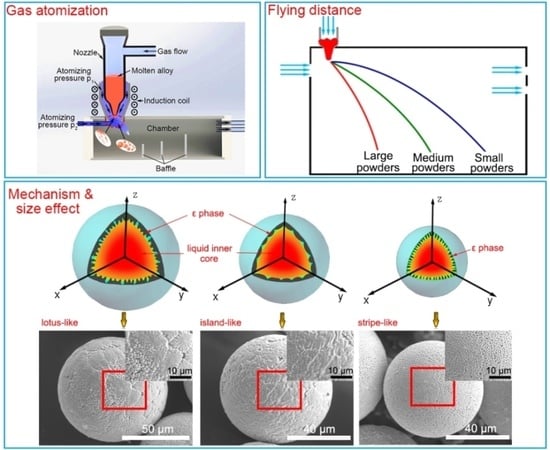
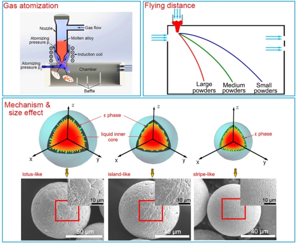
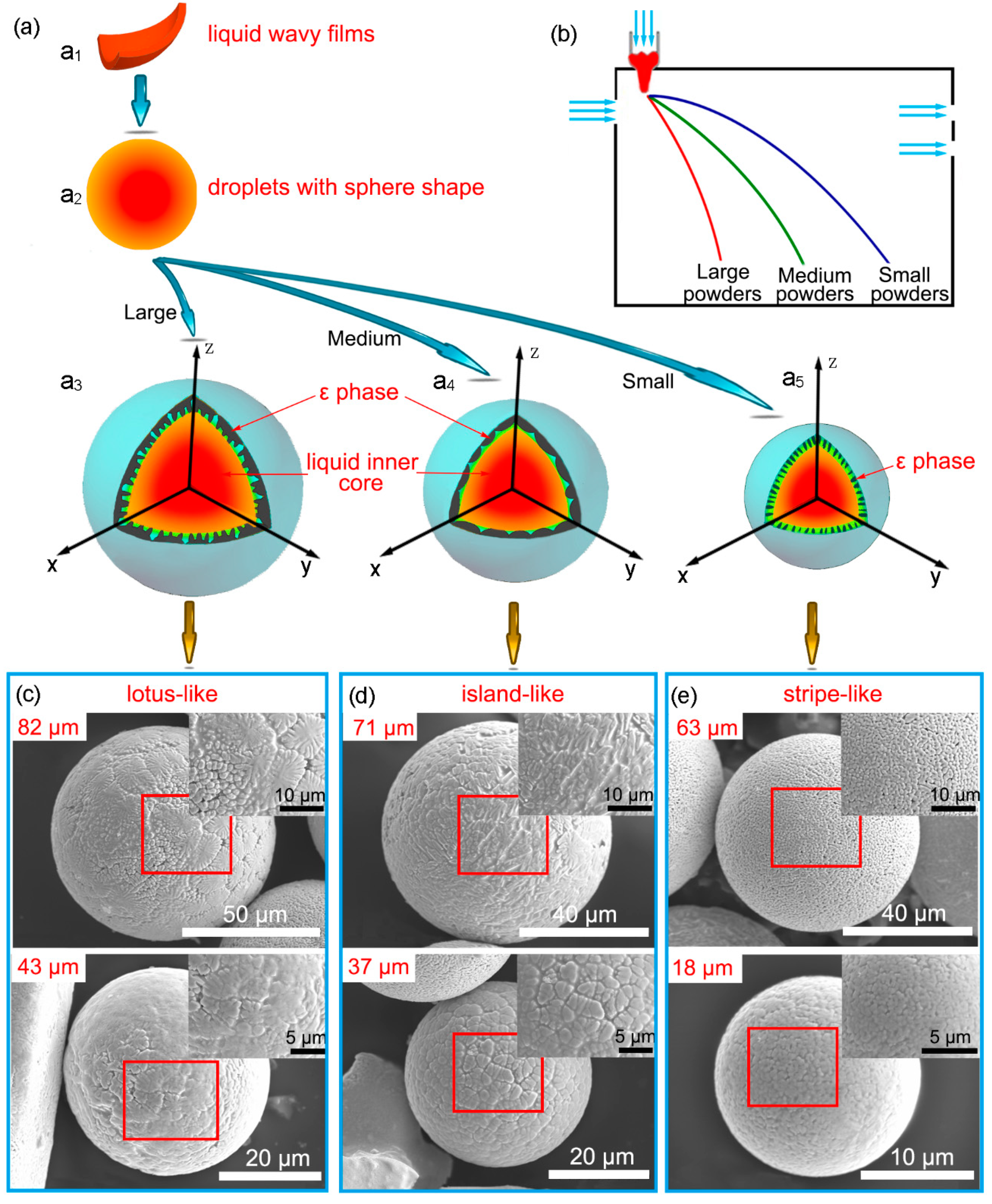
Combined with the analysis mentioned above, a hypothetical model was constructed to explain the solidification of gas-atomized Cu (60.9 wt.%)/Sn powders. During gas atomization, when the melt was impacted by the cold N2, the molten metal was divided into large amounts of unstable melt films, and transformed into wavy films under the gas atmosphere [33]. Figure 8a illustrates the phase transformation model as a function of the flight path (Figure 8b). The wavy films transformed into sphere-shaped droplets (Figure 8a1,a2) and component segregation in the microdomain of the droplet occurred. Figure 8c–e exhibit the morphology of the powders without corrosion.
The Cu3Sn core in the shell of the droplets would have grown inward when the temperature gradient was the largest. When the Cu3Sn core grew along the surface and inside to a certain size, the inner liquid phases of the droplets of approximately 84 μm (Figure 4a) were not cooled down to TP; thus, the peritectic solidification between the Cu3Sn core and the residual liquid phase would not have happened immediately. Instead, the inward growth progressed deeply into the sub-cooled area and continued to grow not only along the original growth direction (the diameter direction of the droplets), but also the direction perpendicular to the original growth direction. However, the supercooling temperature of the liquid between adjacent prominences was lower, such that their crystals protruded more slowly. As the temperature decreased further, the liquid inner core began to crystallize, and the growth of some prominences hindered each other when the outer shell solidified. Faster cooling rates gave rise to shorter crystallization time, resulting in insufficient peritectic reaction, thus yielding the lotus-like microstructure (Figure 4a,d). Therefore, the crystal path model of the droplets of approximately 82 μm and 43 μm was a1–a2–a3–c (Figure 8a,c).
Compared with the droplets of approximately 82 μm and 43 μm (Figure 8c), the growth of the Cu3Sn core of the droplets of 37 μm was relatively restricted because its flying distance was farther from the nozzle and the temperature gradient was lower. Thus, the Cu3Sn core could grow along the surface and inside the droplet to a certain size until the temperature was reduced to TP, followed by incomplete peritectic solidification, as well as solidification of the eutectic η + β. Solidification of their inner cores was slower, such that the inner condensation microstructure was larger in size (Figure 5e,f). The crystallization time was relatively longer, resulting in a relatively adequate peritectic reaction, which would cause the consumption of Cu3Sn and Sn. In the same way, the solidification of the droplets of about 71 μm in size was similar to that of the 37-μm droplets (Figure 8d), due to their larger volume though they were closer to the nozzle. Therefore, their crystal path model was a1–a2–a4–d (Figure 8a,d).
For the droplets of approximately 63 μm and 18 μm in size (Figure 8c), the flying distance was the farthest from the nozzle, and the interior peritectic solidification was adequate because its cooling rate was further reduced, which consumed a relatively larger proportion of the ε phase. Then, when the inner temperature dropped below 227 °C, solidification of the eutectic η + β would have occurred after the peritectic solidification. Therefore, their crystal path model was a1–a2–a5–e (Figure 8a,e).
It was worth noting that the flying path of the droplets of about 43 μm in size (Figure 8) was farther away from the nozzle side than that of droplets 63 μm in size (Figure 8). However, the surface of the droplets of about 43 μm in size exhibited a lotus-like tissue, while the other showed a stripe-like tissue. This is because, for the powder of 63 μm in size, the volume factor was more critical in affecting the supercooling temperature (compared with the powder of 43 μm in size), rather than the flying distance. Thus, for the powder of 63 μm in size, a larger volume meant a lower cooling rate, resulting in greater consumption of the ε phase due to the relatively adequate peritectic reaction during solidification. Thus, the stripe-like tissue emerged.
3.3. Heat Treatment and Potential Application
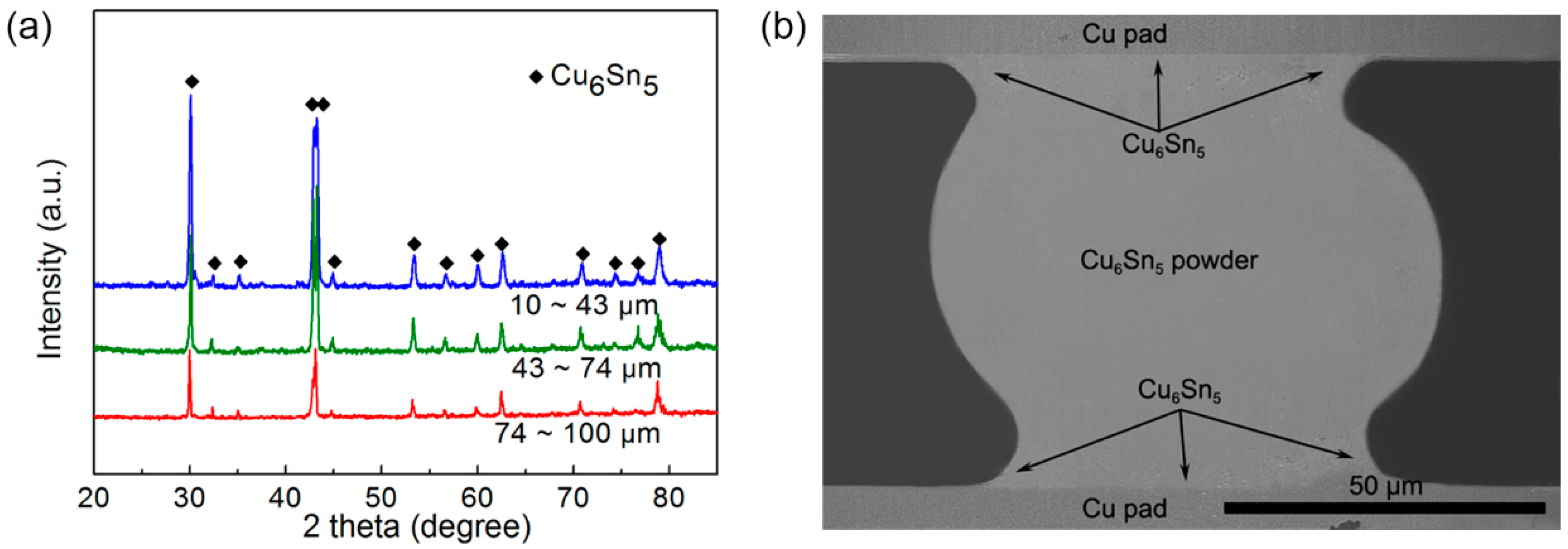
The XRD patterns of atomized powders with different diameters after 300 °C heat treatment for 4 h in an inert atmosphere are shown in Figure 9a. It can be clearly seen that, after long-time heat treatment, the powders consisting of Sn, Cu3Sn, and Cu6Sn5 phases were all transformed into the Cu6Sn5 phase, which was consistent with the fact that the nominal composition of Cu:Sn in the ingot alloy was 6:5 (at.%). Moreover, the cooling rate of the powders in the furnace was slower than 20 °C/min, such that η–η’ transformation occurred [25], which was also reported in the literature [27].
The obtained pure Cu6Sn5 powders can be applied in many fields, such as additive manufacturing and three-dimensional (3D) electronic packaging. Here, these Cu6Sn5 intermetallic powders were applied for high-temperature interconnection to replace the traditional Sn-based solder alloys with low service temperatures. In order to realize the application of the powder, we applied a thin layer of Sn solder paste, which was printed on the two bare copper pads, and then pre-transplanted a Cu6Sn5 ball with a diameter of 80 μm onto the solder paste under a magnifying glass to form a multi-layer structure of Cu/Sn–Cu6Sn5–Sn/Cu. The whole structure was then placed in a tube furnace under an inert gas atmosphere at 240 °C for 5 min. The SEM image of the cross-section of the interconnection is shown in Figure 9b. The Sn phase reacted with the Cu pad and was consumed completely in 5 min, leaving the sole intermetallic of Cu6Sn5 phase in the joint. Thus, such intermetallic interconnections have the potential to be applied in high temperatures (greater than 400 °C). Many researchers found ways to obtain the joints with high melting temperature in a relatively short time. Feng et al. [34] connected Cu substrates with a 50-μm Sn layer (Cu/Sn/Cu sandwich structure) at 260 °C for 4 h, leaving the Cu6Sn5 and Cu3Sn phases in the joint. Yin et al. [35] selected the 10-μm Sn layer as the solder layer, and obtained the full Cu3Sn joint at a high temperature of 500 °C for 3 min. Hu et al. [36] used the Sn-coated Cu core–shell particles mixed with flux as the solder layer, and then obtained the joints consisting of Cu6Sn5 and Cu3Sn phases at 250 °C for 12 min. In our experiment, we obtained the Cu6Sn5 joint at 240 °C for only 5 min and the joint could withstand temperatures over 400 °C. These interconnections, therefore, exhibit considerable potential for application in high-temperature packaging.
4. Conclusions
In the present study, the morphology and microstructural evolution of the undercooled Cu–Sn droplets were systematically analyzed. The main conclusions are listed as follows:
(1) The growth of primary phases (Cu6Sn5 and Cu3Sn) were dependent on the droplet size, and the microstructure observation of the primary phase was consistent with the analysis of the transient nucleation theory.
(2) With the decrease in powder size, the microstructures of the powder surface were found to be in lotus-leaf, island, and stripe shapes. The size of 45 μm might be the critical transition diameter. When the size was below 45 μm, the microstructures mentioned above appeared again.
(3) After thermal treatment, the powders were completely composed of a single Cu6Sn5 phase. Such intermetallic powders can be used in flip-chip packaging. The sole Cu6Sn5 joint was obtained at 240 °C for only 5 min and could withstand temperatures over 400 °C, exhibiting potential for high-temperature packaging.
Author Contributions
Conceptualization, H.P., H.J., and M.L. (Mingyu Li); data curation, H.P., M.L. (Meng Liang), and J.Z.; methodology, H.J. and M.L. (Meng Liang); formal Analysis, H.P., M.L. (Meng Liang), and J.Z.; writing—original draft preparation, H.P.; writing—review and editing, H.P., H.J., and M.L. (Meng Liang); supervision, H.J. and M.L. (Mingyu Li); project administration, H.J.; funding acquisition, H.J.
Funding
This research was funded by the National Natural Science Foundation of China (NSFC 51775140). Part of the research was also funded by the Guangdong Province Natural Science Foundation (2017A030313302) and the Shenzhen Science and Technology Plan (Projects No. JCYJ20170307150122514).
Acknowledgments
This work was supported by the National Natural Science Foundation of China (NSFC 51775140). Part of the work was also supported by the Guangdong Province Natural Science Foundation (2017A030313302) and the Shenzhen Science and Technology Plan (Projects No. JCYJ20170307150122514).
Conflicts of Interest
The authors declare no conflicts of interest.
References
- Samal, C.P.; Parihar, J.S.; Chaira, D. The effect of milling and sintering techniques on mechanical properties of Cu–graphite metal matrix composite prepared by powder metallurgy route. J. Alloys Compd. 2013, 569, 95–101. [Google Scholar] [CrossRef]
- Čapek, J.; Vojtěch, D. Properties of porous magnesium prepared by powder metallurgy. Mater. Sci. Eng. C 2013, 33, 564–569. [Google Scholar] [CrossRef] [PubMed]
- Liu, Z.Y.; Xiao, B.L.; Wang, W.G.; Ma, Z.Y. Tensile strength and electrical conductivity of carbon nanotube reinforced aluminum matrix composites fabricated by powder metallurgy combined with friction stir processing. Mater. Sci. Technol. 2014, 30, 649–655. [Google Scholar] [CrossRef]
- Chauhan, S.; Verma, V.; Prakash, U.; Tewari, P.C.; Khanduja, D. Analysis of powder metallurgy process parameters for mechanical properties of sintered Fe–Cr–Mo alloy steel. Mater. Manuf. Process. 2017, 5, 537–541. [Google Scholar] [CrossRef]
- Bourell, D.; Kruth, J.P.; Leu, M.; Levy, G.; Rosen, D.; Beese, A.M.; Clare, A. Materials for additive manufacturing. CIRP Ann.-Manuf. Technol. 2017, 66, 659–681. [Google Scholar] [CrossRef]
- Zhong, Y.; Liu, L.F.; Wikman, S.; Wikman, S.; Cui, D.Q.; Shen, Z.J. Intragranular cellular segregation network structure strengthening 316L stainless steel prepared by selective laser melting. J. Nucl. Mater. 2016, 470, 170–178. [Google Scholar] [CrossRef]
- Vähä-Nissi, M. Characterization of filled powders for powder coating of paper. Powder Technol. 2015, 279, 127–133. [Google Scholar] [CrossRef]
- Vähä-Nissi, M.; Hildén, S.; Aikala, M. Coating of paper with highly filled powders. Powder Technol. 2016, 294, 185–190. [Google Scholar] [CrossRef]
- Canakci, A.; Varol, T. A novel method for the production of metal powders without conventional atomization process. J. Clean. Prod. 2015, 99, 312–319. [Google Scholar] [CrossRef]
- Shi, S.J.; Jin, Z.J.; Bao, Y.; Jiang, G.N. Study of Milling Time and Process Control Agent on W-Mo-Cr Pre-Alloying Powders. Mater. Manuf. Process. 2016, 31, 926–932. [Google Scholar] [CrossRef]
- Zhao, H.; Zhu, C.; Li, J.; Liu, F.; Zheng, Z. The synthesis and electrochemical performance of Cu6Sn5 intermetallic nanoparticles as anode material in Li ion batteries. Int. J. Mater. Res. 2016, 107, 766–768. [Google Scholar] [CrossRef]
- Xia, Z.; Jin, S.; Liu, K. Preparation and Thermal Stability of Ultrafine Nickel Powders Containing hcp-Ni Nanocrystallites Using Liquid-Phase Reduction Method. Metall. Mater. Trans. B 2016, 46, 2793–2798. [Google Scholar] [CrossRef]
- Li, L.; Zou, H.; Cai, S. Thermal behavior of gas atomised Al-20Mg-2Zr alloy powder. Mater. Sci. Technol.-Lond. 2016, 32, 863–870. [Google Scholar] [CrossRef]
- Tourret, D.; Reinhart, G.; Gandin, C.; Iles, G.N.; Dahlborg, U.; Calvo-Dahlborg, M.; Bao, C.M. Gas Atomization of Al-Ni Powders: Solidification Modeling and Neutron Diffraction Analysis. Acta Mater. 2011, 59, 6658–6669. [Google Scholar] [CrossRef]
- Young, K.; Ouchi, T.; Banik, A.; Koch, J.; Fetcenko, M.A.; Bendersky, L.A.; Wang, K.; Vaudin, M. Gas Atomization of Cu-modified AB5 Metal Hydride Alloys. J. Alloys Compd. 2011, 509, 4896–4904. [Google Scholar] [CrossRef]
- Osório, W.R.; Spinelli, J.E.; Afonso, C.R.M.; Peixoto, L.C.; Garcia, A. Electrochemical Corrosion Behavior of Gas Atomized Al-Ni Alloy Powders. Electrochim. Acta 2012, 69, 371–378. [Google Scholar] [CrossRef]
- Allimant, A.; Planche, M.P.; Bailly, Y.; Dembinski, L.; Coddet, C. Progress in gas atomization of liquid metals by means of a De Laval nozzle. Powder Technol. 2009, 190, 79–83. [Google Scholar] [CrossRef]
- Planche, M.P.; Khatim, O.; Dembinski, L.; Coddet, C.; Girardot, L.; Bailly, Y. Velocities of copper droplets in the De Laval atomization process. Powder Technol. 2012, 229, 191–198. [Google Scholar] [CrossRef]
- Wang, C.P.; Liu, X.J.; Ohnuma, I.; Kainuma, R.; Ishida, K. Formation of Immiscible Alloy Powders with Egg-Type Microstructure. Science 2002, 297, 990–993. [Google Scholar] [CrossRef]
- Guo, Y.L.; Jia, L.; Kong, B.; Zhang, S.N.; Zhang, F.X.; Zhang, H. Microstructure and surface oxides of rapidly solidified Nb-Si based alloy powders. Mater. Des. 2017, 120, 109–116. [Google Scholar] [CrossRef]
- Yang, D.Y.; Guo, S.; Peng, H.X.; Cao, F.Y.; Liu, N.; Sun, J.F. Size dependent phase transformation in atomized TiAl powders. Intermetallics 2015, 61, 72–79. [Google Scholar] [CrossRef]
- Yule, A.J.; Dunkley, J.J. Atomization of Melt, 1st ed.; Oxford University Press: Oxford, UK, 1994. [Google Scholar]
- Guildenbecher, D.R.; Lopez-Rivera, C.; Sojka, P.E. Secondary atomization. Exp. Fluids 2009, 46, 371–402. [Google Scholar] [CrossRef]
- Seki, Y.; Okamoto, S.; Takisawa, H.; Kawai, N. Effect of atomization variables on powder characteristics in the high-pressured water atomization process. Met. Powder Rep. 1990, 45, 38–40. [Google Scholar] [CrossRef]
- Nogita, K.; Gourlay, C.M.; McDonald, S.D.; Wu, Y.Q.; Read, J.; Gu, Q.F. Kinetics of the η-η’ transformation in Cu6Sn5. Scr. Mater. 2011, 65, 922–925. [Google Scholar] [CrossRef]
- StJohn, D.H. The peritectic reaction. Acta Metall. Mater. 1990, 38, 631–636. [Google Scholar] [CrossRef]
- Tongsri, R.; Yotkaew, T.; Krataitong, R.; Wila, P.; Sir-on, A.; Muthitamongkol, P.; Tosangthum, N. Characterization of Cu6Sn5 intermetallic powders produced by water atomization and powder heat treatment. Mater. Charact. 2013, 86, 167–176. [Google Scholar] [CrossRef]
- Zhai, W.; Wei, B. Direct nucleation and growth of peritectic phase induced by substantial undercooling condition. Mater. Lett. 2013, 108, 145–148. [Google Scholar] [CrossRef]
- Tongsri, R.; Dashwood, R.; McShane, H. Microstructure and solidification of Al-Fe-(V, Si) alloy powders. Sci. Asia 2004, 30, 33–41. [Google Scholar] [CrossRef]
- Kim, T.; Lee, B.; Lee, C.R.; Chun, B. Microstructure of rapidly solidified Al–20Si alloy powders. Mater. Sci. Eng. A 2001, 304–306, 617–620. [Google Scholar] [CrossRef]
- Chen, Y.Z.; Liu, F.; Yang, G.C.; Liu, N.; Yang, C.L.; Zhou, Y.H. Suppression of peritectic reaction in the undercooled peritectic Fe-Ni melts. Scr. Mater. 2007, 57, 779–782. [Google Scholar] [CrossRef]
- Liu, N.; Liu, F.; Yang, C.L.; Chen, Y.Z.; Yang, G.C.; Zhou, Y.H. Peritectic solidification of undercooled Fe-Co alloys. J. Alloys Compd. 2008, 465, 391–395. [Google Scholar] [CrossRef]
- Dombrowski, N.; Johns, W.R. The aerodynamic instability and disintegration of viscous liquid sheets. Chem. Eng. Sci. 1963, 18, 203–214. [Google Scholar] [CrossRef]
- Feng, J.; Hang, C.; Tian, Y.; Liu, B.; Wang, C. Growth kinetics of Cu6Sn5 intermetallic compound in Cu-liquid Sn interfacial reaction enhanced by electric current. Sci. Rep. 2018, 8, 1775. [Google Scholar] [CrossRef] [PubMed]
- Yin, Z.; Sun, F.; Guo, M. The fast formation of Cu-Sn intermetallic compound in Cu/Sn/Cu system by induction heating process. Mater. Lett. 2018, 215, 207–210. [Google Scholar] [CrossRef]
- Hu, T.Q.; Chen, H.T.; Li, M.Y. Fabrication of Cu@Sn Core-Shell Structured Particles and the Application in High Remelting Temperature Bonding. Mater. Sci. Forum 2016, 878, 3–7. [Google Scholar] [CrossRef]
Figure 1.
Schematic illustration of the gas atomizer.

Figure 2.
Distribution of powder sizes of gas-atomized Cu (60.9 wt.%)/Sn alloy.

Figure 3.
X-ray diffraction (XRD) patterns (a), and differential scanning calorimetry (DSC) patterns (b) of the atomized Cu–Sn alloy powders with different size.
Figure 3.
X-ray diffraction (XRD) patterns (a), and differential scanning calorimetry (DSC) patterns (b) of the atomized Cu–Sn alloy powders with different size.
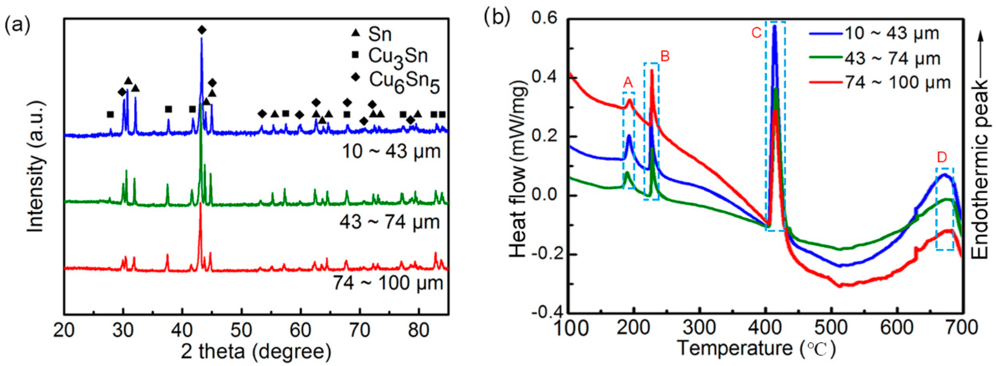
Figure 4.
Surface morphology and microstructures of powders with different diameters after being etched with a 10% hydrochloric acid/ethanol solution for 24 h. The powder sizes were (a) 84 μm, (b) 72 μm, (c) 59 μm, (d) 44 μm, (e) 36 μm, and (f) 19 μm. Corresponding enlarged images and compositions are shown to the right.

Figure 5.
Interior microstructures of powders with different diameters with sizes of (a) 82 μm, (b) 70 μm, (c) 59 μm, (d) 38 μm, (e) 34 μm, and (f) 22 μm. Corresponding enlarged images and compositions are shown to the right.
Figure 5.
Interior microstructures of powders with different diameters with sizes of (a) 82 μm, (b) 70 μm, (c) 59 μm, (d) 38 μm, (e) 34 μm, and (f) 22 μm. Corresponding enlarged images and compositions are shown to the right.
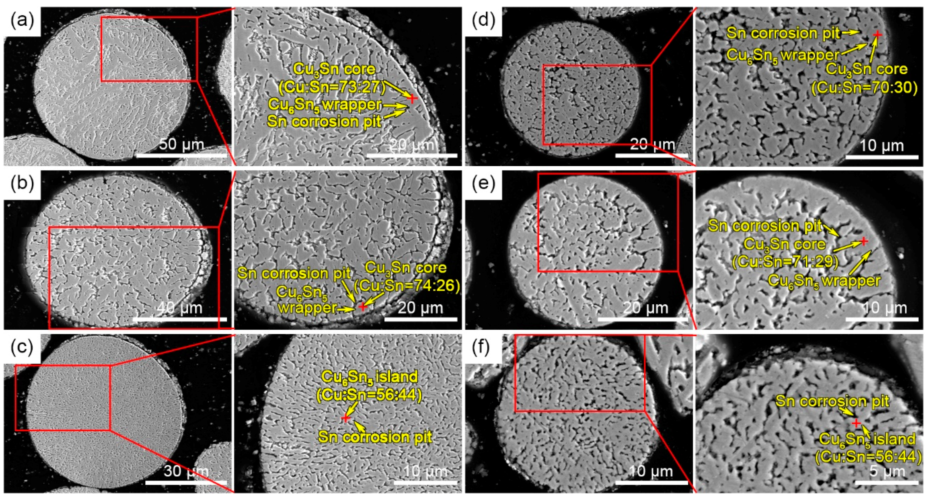
Figure 6.
Typical microstructures of cross-sectional powder with sizes of (a) 82 μm and (b) 59 μm. (c,d) Corresponding energy-dispersive X-ray spectroscopy (EDS) line-scanning of the marked lines in (a,b).
Figure 6.
Typical microstructures of cross-sectional powder with sizes of (a) 82 μm and (b) 59 μm. (c,d) Corresponding energy-dispersive X-ray spectroscopy (EDS) line-scanning of the marked lines in (a,b).

Figure 7.
The Cu–Sn phase diagram [27].
Figure 7.
The Cu–Sn phase diagram [27].

Figure 8.
A schematic illustration of the phase transformation mechanism (a) as a function of the flying track (b); the morphology of powders without corrosion with a series of diameters of (c) 82 μm and 43 μm, (d) 71 μm and 37 μm, and (e) 63 μm and 18 μm.
Figure 8.
A schematic illustration of the phase transformation mechanism (a) as a function of the flying track (b); the morphology of powders without corrosion with a series of diameters of (c) 82 μm and 43 μm, (d) 71 μm and 37 μm, and (e) 63 μm and 18 μm.

Figure 9.
(a) XRD patterns of atomized powders as a function of power size after heat treatment at 300 °C for 4 h; (b) interconnection application of the Cu6Sn5 intermetallic powder.
Figure 9.
(a) XRD patterns of atomized powders as a function of power size after heat treatment at 300 °C for 4 h; (b) interconnection application of the Cu6Sn5 intermetallic powder.
© 2019 by the authors. Licensee MDPI, Basel, Switzerland. This article is an open access article distributed under the terms and conditions of the Creative Commons Attribution (CC BY) license (http://creativecommons.org/licenses/by/4.0/).
Share and Cite
MDPI and ACS Style
Pan, H.; Ji, H.; Liang, M.; Zhou, J.; Li, M. Size-Dependent Phase Transformation during Gas Atomization Process of Cu–Sn Alloy Powders. Materials 2019, 12, 245. https://doi.org/10.3390/ma12020245
AMA Style
Pan H, Ji H, Liang M, Zhou J, Li M. Size-Dependent Phase Transformation during Gas Atomization Process of Cu–Sn Alloy Powders. Materials. 2019; 12(2):245. https://doi.org/10.3390/ma12020245
Chicago/Turabian StylePan, Hao, Hongjun Ji, Meng Liang, Junbo Zhou, and Mingyu Li. 2019. "Size-Dependent Phase Transformation during Gas Atomization Process of Cu–Sn Alloy Powders" Materials 12, no. 2: 245. https://doi.org/10.3390/ma12020245
Note that from the first issue of 2016, this journal uses article numbers instead of page numbers. See further details here.