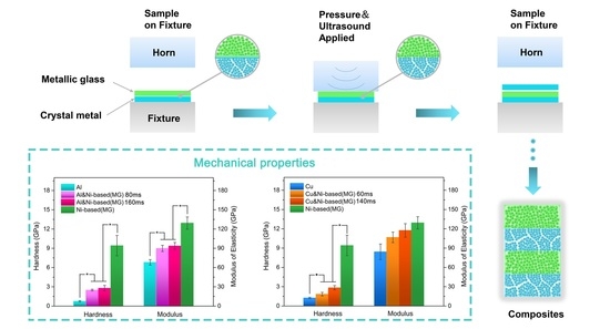
Experiments on the Ultrasonic Bonding Additive Manufacturing of Metallic Glass and Crystalline Metal Composite

 ,
,
Abstract
:
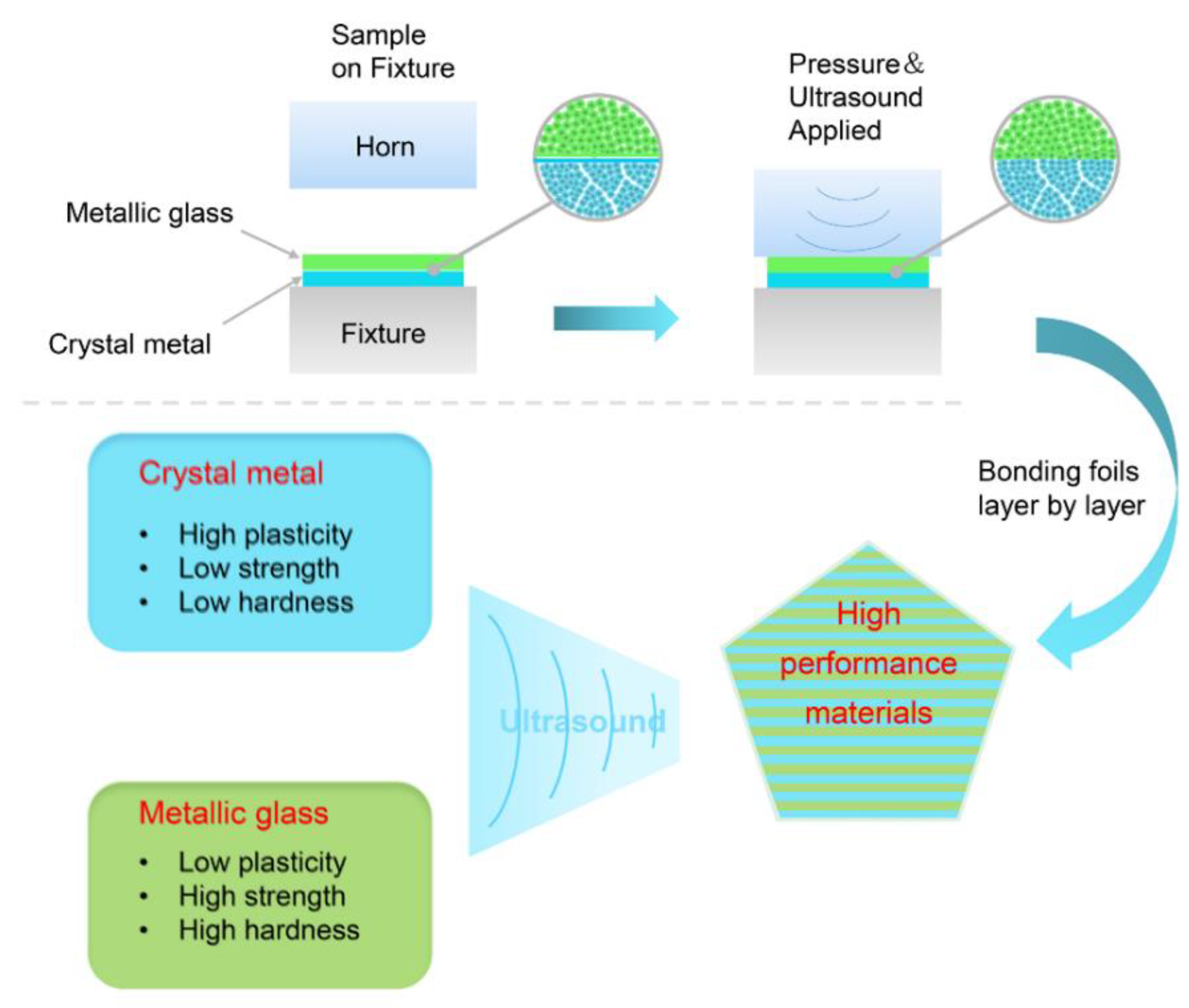
1. Introduction
2. Material and Methods
3. Results and Discussion
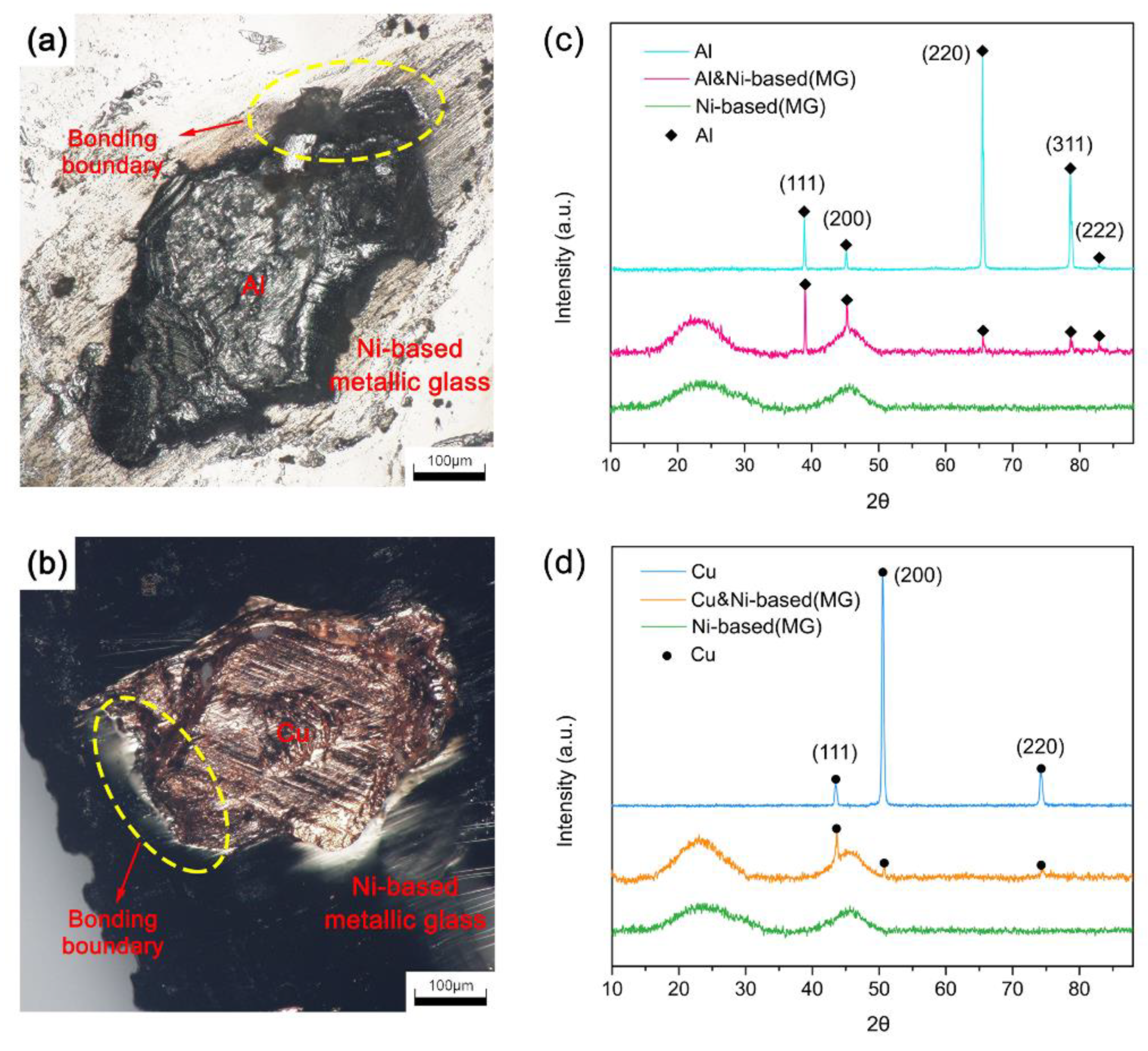
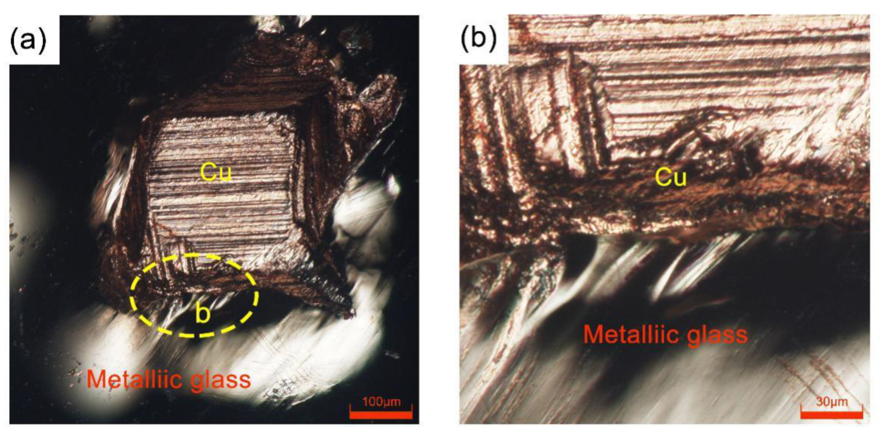
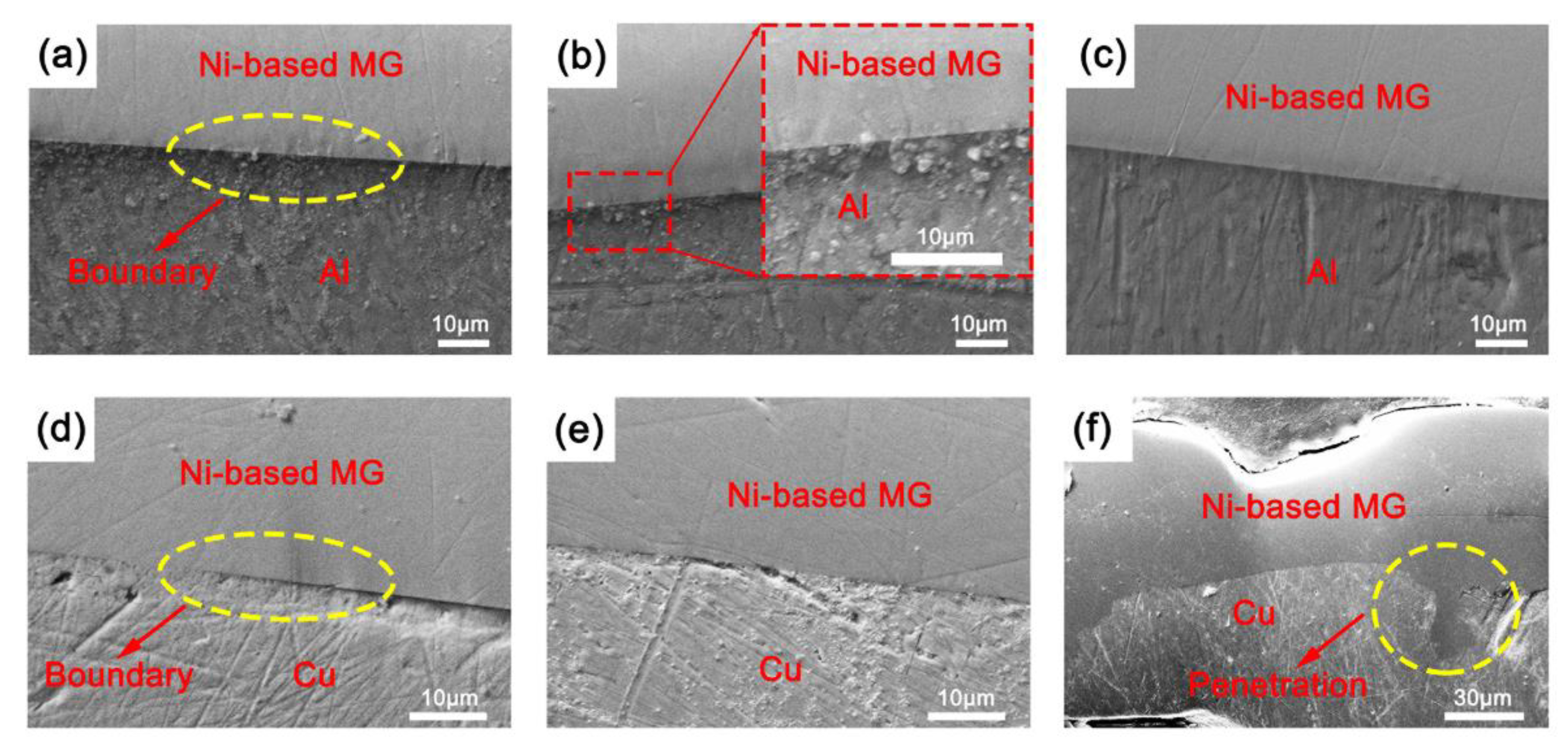
3.1. SEM of the Cross-Sectional Morphology
3.2. Phase Analysis at the Joint Interface
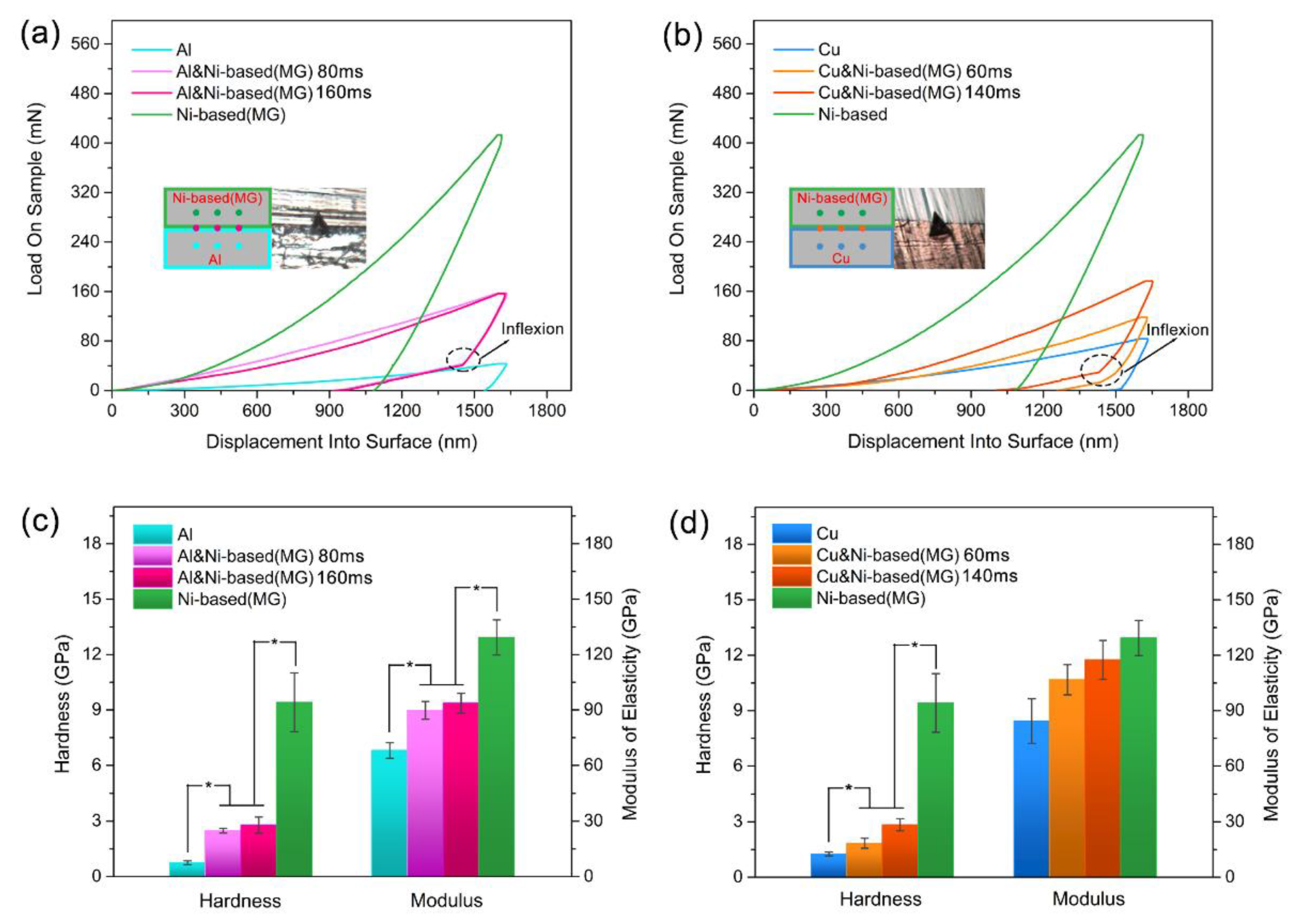
3.3. Hardness and Modulus Inside the Consolidated Samples
4. Conclusions
Author Contributions
Funding
Conflicts of Interest
References
- Ma, E.; Ding, J. Tailoring structural inhomogeneities in metallic glasses to enable tensile ductility at room temperature. Mater. Today 2016, 19, 568–579. [Google Scholar] [CrossRef]
- Zhang, F.; Wu, J.; Jiang, W.; Hu, Q.; Zhang, B. New and Efficient Electrocatalyst for Hydrogen Production from Water Splitting: Inexpensive, Robust Metallic Glassy Ribbons Based on Iron and Cobalt. ACS Appl. Mater. Interfaces 2017, 9, 31340–31344. [Google Scholar] [CrossRef] [PubMed]
- Sheng, H.W.; Luo, W.K.; Alamgir, F.M.; Bai, J.M.; Ma, E. Atomic packing and short-to-medium-range order in metallic glasses. Nature 2006, 439, 419–425. [Google Scholar] [CrossRef] [PubMed]
- Trexler, M.M.; Thadhani, N.N. Mechanical properties of bulk metallic glasses. Prog. Mater. Sci. 2010, 55, 759–839. [Google Scholar] [CrossRef]
- Meagher, P.; O’Cearbhaill, E.D.; Byrne, J.H.; Browne, D.J. Bulk Metallic Glasses for Implantable Medical Devices and Surgical Tools. Adv. Mater. 2016, 28, 5755–5762. [Google Scholar] [CrossRef] [PubMed] [Green Version]
- Sekol, R.C.; Kumar, G.; Carmo, M.; Gittleson, F.; Hardesty-Dyck, N.; Mukherjee, S.; Schroers, J.; Taylor, A.D. Bulk metallic glass micro fuel cell. Small 2013, 9, 2081–2085. [Google Scholar] [CrossRef]
- Li, H.F.; Zheng, Y.F. Recent advances in bulk metallic glasses for biomedical applications. Acta Biomater 2016, 36, 1–20. [Google Scholar] [CrossRef] [PubMed]
- Wang, W.H. Bulk Metallic Glasses with Functional Physical Properties. Adv. Mater. 2009, 21, 4524–4544. [Google Scholar] [CrossRef]
- Chen, W.; Zhou, H.; Liu, Z.; Ketkaew, J.; Shao, L.; Li, N.; Gong, P.; Samela, W.; Gao, H.; Schroers, J. Test sample geometry for fracture toughness measurements of bulk metallic glasses. Acta Mater. 2018, 145, 477–487. [Google Scholar] [CrossRef]
- Li, H.X.; Lu, Z.C.; Wang, S.L.; Wu, Y.; Lu, Z.P. Fe-based bulk metallic glasses: Glass formation, fabrication, properties and applications. Prog. Mater. Sci. 2019, 103, 235–318. [Google Scholar] [CrossRef]
- Dudina, D.V.; Georgarakis, K.; Aljerf, M.; Li, Y.; Braccini, M.; Yavari, A.R.; Inoue, A. Cu-based metallic glass particle additions to significantly improve overall compressive properties of an Al alloy. Compos. Part. A Appl. Sci. Manuf. 2010, 41, 1551–1557. [Google Scholar] [CrossRef]
- Chuai, D.; Liu, X.; Yu, R.; Ye, J.; Shi, Y. Enhanced microwave absorption properties of flake-shaped FePCB metallic glass/graphene composites. Compos. Part. A Appl. Sci. Manuf. 2016, 89, 33–39. [Google Scholar] [CrossRef]
- Kruzic, J.J. Bulk Metallic Glasses as Structural Materials: A Review. Adv. Eng. Mater. 2016, 18, 1308–1331. [Google Scholar] [CrossRef]
- Żrodowski, Ł.; Wysocki, B.; Wróblewski, R.; Krawczyńska, A.; Adamczyk-Cieślak, B.; Zdunek, J.; Błyskun, P.; Ferenc, J.; Leonowicz, M.; Święszkowski, W. New approach to amorphization of alloys with low glass forming ability via selective laser melting. J. Alloy. Compd. 2019, 771, 769–776. [Google Scholar] [CrossRef]
- Pauly, S.; Löber, L.; Petters, R.; Stoica, M.; Scudino, S.; Kühn, U.; Eckert, J. Processing metallic glasses by selective laser melting. Mater. Today 2013, 16, 37–41. [Google Scholar] [CrossRef]
- Mahbooba, Z.; Thorsson, L.; Unosson, M.; Skoglund, P.; West, H.; Horn, T.; Rock, C.; Vogli, E.; Harrysson, O. Additive manufacturing of an iron-based bulk metallic glass larger than the critical casting thickness. Appl. Mater. Today 2018, 11, 264–269. [Google Scholar] [CrossRef]
- Guo, S.; Wang, M.; Zhao, Z.; Zhang, Y.Y.; Lin, X.; Huang, W.D. Molecular dynamics simulation on the micro-structural evolution in heat-affected zone during the preparation of bulk metallic glasses with selective laser melting. J. Alloy. Compd. 2017, 697, 443–449. [Google Scholar] [CrossRef]
- Li, X. Additive Manufacturing of Advanced Multi-Component Alloys: Bulk Metallic Glasses and High Entropy Alloys. Adv. Eng. Mater. 2018, 20, 1700874. [Google Scholar] [CrossRef]
- Gibson, M.A.; Mykulowycz, N.M.; Shim, J.; Fontana, R.; Schmitt, P.; Roberts, A.; Ketkaew, J.; Shao, L.; Chen, W.; Bordeenithikasem, P.; et al. 3D printing metals like thermoplastics: Fused filament fabrication of metallic glasses. Mater. Today 2018, 21, 697–702. [Google Scholar] [CrossRef]
- Ouyang, D.; Xing, W.; Li, N.; Li, Y.; Liu, L. Structural evolutions in 3D-printed Fe-based metallic glass fabricated by selective laser melting. Addit. Manuf. 2018, 23, 246–252. [Google Scholar] [CrossRef]
- Bordeenithikasem, P.; Stolpe, M.; Elsen, A.; Hofmann, D.C. Glass forming ability, flexural strength, and wear properties of additively manufactured Zr-based bulk metallic glasses produced through laser powder bed fusion. Addit. Manuf. 2018, 21, 312–317. [Google Scholar] [CrossRef]
- Bordeenithikasem, P.; Shen, Y.; Tsai, H.-L.; Hofmann, D.C. Enhanced mechanical properties of additively manufactured bulk metallic glasses produced through laser foil printing from continuous sheetmetal feedstock. Addit. Manuf. 2018, 19, 95–103. [Google Scholar] [CrossRef]
- Ashby, M.; Greer, A. Metallic glasses as structural materials. Scr. Mater. 2006, 54, 321–326. [Google Scholar] [CrossRef]
- Hufnagel, T.C.; Schuh, C.A.; Falk, M.L. Deformation of metallic glasses: Recent developments in theory, simulations, and experiments. Acta Mater. 2016, 109, 375–393. [Google Scholar] [CrossRef] [Green Version]
- Li, N.; Zhang, J.; Xing, W.; Ouyang, D.; Liu, L. 3D printing of Fe-based bulk metallic glass composites with combined high strength and fracture toughness. Mater. Des. 2018, 143, 285–296. [Google Scholar] [CrossRef]
- Kim, J.; Kawamura, Y. Dissimilar welding of Zr41Be23Ti14Cu12Ni10 bulk metallic glass and stainless steel. Scr. Mater. 2011, 65, 1033–1036. [Google Scholar] [CrossRef]
- Li, Y.; Shen, Y.; Chen, C.; Leu, M.C.; Tsai, H.-L. Building metallic glass structures on crystalline metal substrates by laser-foil-printing additive manufacturing. J. Mater. Process. Technol. 2017, 248, 249–261. [Google Scholar] [CrossRef]
- Li, Y.; Shen, Y.; Leu, M.C.; Tsai, H.-L. Building Zr-based metallic glass part on Ti-6Al-4V substrate by laser-foil-printing additive manufacturing. Acta Mater. 2018, 144, 810–821. [Google Scholar] [CrossRef]
- Feng, J.; Chen, P.; Zhou, Q. Investigation on Explosive Welding of Zr53Cu35Al12 Bulk Metallic Glass with Crystalline Copper. J. Mater. Eng. Perform. 2018, 27, 2932–2937. [Google Scholar] [CrossRef]
- Wang, X.; Luo, Y.; Huang, T.; Liu, H. Experimental Investigation on Laser Impact Welding of Fe-Based Amorphous Alloys to Crystalline Copper. Materials 2017, 10, 523. [Google Scholar] [CrossRef]
- Ward, A.A.; Zhang, Y.; Cordero, Z.C. Junction growth in ultrasonic spot welding and ultrasonic additive manufacturing. Acta Mater. 2018, 158, 393–406. [Google Scholar] [CrossRef]
- Levy, A.; Miriyev, A.; Sridharan, N.; Han, T.; Tuval, E.; Babu, S.S.; Dapino, M.J.; Frage, N. Ultrasonic additive manufacturing of steel: Method, post-processing treatments and properties. J. Mater. Process. Technol. 2018, 256, 183–189. [Google Scholar] [CrossRef]
- Lin, J.-Y.; Nambu, S.; Koseki, T. Evolution of bonding interface during ultrasonic welding between steel and aluminium alloy. Sci. Technol. Weld. Join. 2018, 24, 83–91. [Google Scholar] [CrossRef]
- Wu, W.; Jiang, J.; Li, G.; Fuh, J.Y.H.; Jiang, H.; Gou, P.; Zhang, L.; Liu, W.; Zhao, J. Ultrasonic additive manufacturing of bulk Ni-based metallic glass. J. Non-Cryst. Solids 2019, 506, 1–5. [Google Scholar] [CrossRef]
- Warcholinski, B.; Gilewicz, A.; Kuprin, A.S.; Tolmachova, G.N.; Ovcharenko, V.D.; Kuznetsova, T.A.; Zubar, T.I.; Khudoley, A.L.; Chizhik, S.A. Mechanical properties of Cr-O-N coatings deposited by cathodic arc evaporation. Vacuum 2018, 156, 97–107. [Google Scholar] [CrossRef]
- Warcholinski, B.; Gilewicz, A.; Kuznetsova, T.A.; Zubar, T.I.; Chizhik, S.A.; Abetkovskaia, S.O.; Lapitskaya, V.A. Mechanical properties of Mo(C)N coatings deposited using cathodic arc evaporation. Surf. Coat. Technol. 2017, 319, 117–128. [Google Scholar] [CrossRef]
- Zavaleyev, V.; Walkowicz, J.; Kuznetsova, T.; Zubar, T. The dependence of the structure and mechanical properties of thin ta-C coatings deposited using electromagnetic venetian blind plasma filter on their thickness. Thin Solid Film. 2017, 638, 153–158. [Google Scholar] [CrossRef]


| Material | Fixed Factors | Control Factors | ||||
|---|---|---|---|---|---|---|
| Factor | Level | Unit | Factor | Value | Unit | |
| Ni-based (MG) and Al | Pressure | 0.18 | MPa | Bonding time | 60 | ms |
| Delay time | 40 | ms | 80 | |||
| Hold time | 50 | ms | 160 | |||
| Ni-based (MG) and Cu | Pressure | 0.18 | MPa | Bonding time | 40 | ms |
| Delay time | 40 | ms | 60 | |||
| Hold time | 50 | ms | 140 | |||
| Materials | Ni-based (MG) and Al | Ni-based (MG) and Cu | ||||
|---|---|---|---|---|---|---|
| Bonding time (ms) | 60 | 80 | 160 | 40 | 60 | 140 |
| Force (N) | 11.71 ± 3.24 | 12.61 ± 1.22 | 7.23 ± 1.97 | 10.82 ± 0.90 | 10.71 ± 1.61 | 5.85 ± 1.50 |
| Samples | H/E | H3/E2 (GPa) |
|---|---|---|
| Al | 0.01111 ± 0.00185 | 0.00010 ± 0.00004 |
| Ni-based (MG) and Al (80 ms) | 0.02776 ± 0.00005 | 0.00192 ± 0.00009 |
| Ni-based (MG) and Al (160 ms) | 0.02977 ± 0.00368 | 0.00256 ± 0.00106 |
| Ni-based (MG) | 0.06726 ± 0.00279 | 0.03948 ± 0.00588 |
| Ni-based (MG) and Cu (60 ms) | 0.01722 ± 0.00125 | 0.00056 ± 0.00016 |
| Ni-based (MG) and Cu (140 ms) | 0.02413 ± 0.00099 | 0.00166 ± 0.00030 |
| Cu | 0.01527 ± 0.00356 | 0.00031 ± 0.00018 |
© 2019 by the authors. Licensee MDPI, Basel, Switzerland. This article is an open access article distributed under the terms and conditions of the Creative Commons Attribution (CC BY) license (http://creativecommons.org/licenses/by/4.0/).
Share and Cite
Li, G.; Zhao, J.; Fuh, J.Y.H.; Wu, W.; Jiang, J.; Wang, T.; Chang, S. Experiments on the Ultrasonic Bonding Additive Manufacturing of Metallic Glass and Crystalline Metal Composite. Materials 2019, 12, 2975. https://doi.org/10.3390/ma12182975
Li G, Zhao J, Fuh JYH, Wu W, Jiang J, Wang T, Chang S. Experiments on the Ultrasonic Bonding Additive Manufacturing of Metallic Glass and Crystalline Metal Composite. Materials. 2019; 12(18):2975. https://doi.org/10.3390/ma12182975
Chicago/Turabian StyleLi, Guiwei, Ji Zhao, Jerry Ying Hsi Fuh, Wenzheng Wu, Jili Jiang, Tianqi Wang, and Shuai Chang. 2019. "Experiments on the Ultrasonic Bonding Additive Manufacturing of Metallic Glass and Crystalline Metal Composite" Materials 12, no. 18: 2975. https://doi.org/10.3390/ma12182975