Article

Ablation Behavior of the SiC-Coated Three-Dimensional Highly Thermal Conductive Mesophase-Pitch-Based Carbon-Fiber-Reinforced Carbon Matrix Composite under Plasma Flame

1
College of Materials Science and Engineering, Hunan Province Key Laboratory for Advanced Carbon Materials and Applied Technology, Hunan University, Changsha 410082, China
2
Hunan Province Engineering Research Center for High Performance Pitch Based Carbon Fiber, Hunan Toyi Carbon Material Technology Co., Ltd., Changsha 410000, China
3
The State Key Laboratory of Refractories and Metallurgy, Wuhan University of Science and Technology, Wuhan 430081, China
*
Authors to whom correspondence should be addressed.
Materials 2019, 12(17), 2723; https://doi.org/10.3390/ma12172723
Submission received: 7 July 2019 / Revised: 20 August 2019 / Accepted: 22 August 2019 / Published: 25 August 2019

Abstract

:
This study is focused on a novel high-thermal-conductive C/C composite used in heat-redistribution thermal protection systems. The 3D mesophase pitch-based carbon fiber (CFMP) preform was prepared using CFMP in the X (Y) direction and polyacrylonitrile carbon fiber (CFPAN) in the Z direction. After the preform was densified by chemical vapor infiltration (CVI) and polymer infiltration and pyrolysis (PIP), the 3D high-thermal-conductive C/C (CMP/C) composite was obtained. The prepared CMP/C composite has higher thermal conduction in the X and Y directions. After an ablation test, the CFPAN becomes needle-shaped, while the CFMP shows a wedge shape. The fiber/matrix and matrix/matrix interfaces are preferentially oxidized and damaged during ablation. After being coated by SiC coating, the thermal conductivity plays a significant role in decreasing the hot-side temperature and protecting the SiC coating from erosion by flame. The SiC-coated CMP/C composite has better ablation resistance than the SiC-coated CPAN/C composite. The mass ablation rate of the sample is 0.19 mg·(cm−2·s−1), and the linear ablation rate is 0.52 μm·s−1.

Graphical Abstract

1. Introduction

Carbon-fiber-reinforced carbon matrix (C/C) composite has been widely studied due to its high-temperature strength, low coefficient of thermal expansion, and good anti-ablation ability [1,2]. Because of its excellent performance, C/C composite has become a promising structural material in high-temperature applications, including rocket nozzles, aeronautic jet engines, leading edges, and so on. C/C composite is also a promising functional material for thermal management systems due to its high thermal conductivity [3,4]. Because it can decrease the temperature of hot components and consequently increase their reliability, C/C composite has been used in heat-redistribution thermal-protection systems of hypersonic aircraft that have undergone long-time ablation and oxidation [5].
There have been many studies on the effects of voids, carbon fibers, and matrix and the interfaces between them on the mechanical and thermal performance of C/C composites. Lachaud et al. [6] set up a modeling strategy to predict 3D C/C composite ablation behavior, and the models were consistent with the experimental data. Lee et al. [7] characterized the surface microstructure of a 2D CPAN/C composite and found that the transverse CFPAN of flank surface had a random orientation of basal planes that was different from the fiber surface. Baxter et al. [8] studied the effect of chemical vapor infiltration (CVI) on the corrosion and thermal conduction of porous C/C composite, and found that both radiative heat transfer and the heat transfer path in pores played important roles in the parallel path thermal conduction. The ablation behavior of C/C composite was also studied by other researchers [9,10]. As for high-thermal-conductive C/C composite, carbon fiber (CF) is not only the reinforcement of the composite, but also the carrier of heat [11]. The morphology, crystal orientation, and crystallite structure of the carbon fiber have an obvious influence on the heat transfer of C/C composite [12,13]. Polyacrylonitrile (PAN)-based and pitch-based carbon fibers are the most common carbon fibers [14,15]. In comparison with PAN-based carbon fiber (CFPAN), mesophase pitch-based carbon fiber (CFMP) has higher thermal conductivity due to fewer lattice defects, higher preferred orientation, and larger graphite crystallite size [15,16]. Therefore, CFMP is an ideal reinforcement for CMP/C composite with high thermal conductivity. Many studies have focused on developing high-thermal-conductive CMP/C composites. Yuan et al. [17] prepared a 1D ribbon-shaped carbon-fiber-reinforced CMP/C composite, and the longitudinal thermal conductivity was about 900 W·(m−1 K−1) after graphitization. Adams et al. [18] and Manocha et al. [4] analyzed the microstructure and thermophysical properties of CMP/C composite. Although much data has been reported in the literature on the fabrication of high-thermal-conductive CMP/C composite [18] and there has been evaluation of the thermophysical properties [19,20] and analysis of the thermal conductivity mechanism [21,22], there have been few reports on the ablation behavior of CMP/C composite, which is worth exploring. It is known that the microstructures and properties of CFMP and CFPAN are evidently different. High-thermal-conductive CFMP has been proven to have a perfect graphite crystal structure highly oriented along the fiber axis direction, while CFPAN exhibits a turbostratic structure composed of entangled and wrinkled crystallites [13,16]. Therefore, it can be speculated that CMP/C composite using CFMP as reinforcement will have some different ablation features. Such understanding of the ablation behavior of CMP/C composite is helpful in applying this composite to thermal protection systems of hypersonic vehicles, especially in explaining the failure mechanisms after the thermal protection coating is damaged. In addition, poor oxidation resistance of carbon materials (above 500 °C) has greatly restricted the application of CMP/C composite under high-temperature environments. Therefore, a thermal protective coating is also needed to make the high thermal conductivity play its positive role in ablation [23,24]. All of this should be experimentally investigated.
In this paper, we report the ablation behavior of a novel homemade 3D CMP/C composite with high thermal conductivity. The CMP/C composite was prepared using CFMP as the reinforcement and heat carrier in the X (Y) direction and CFPAN in the Z direction. The influence of thermal diffusion and structure on the ablation behavior of CMP/C composite with and without SiC coating is elucidated. This study can provide guidance for the design and fabrication of CMP/C composite with high thermal conductivity for application in hypersonic aircrafts.

2. Experimental Procedures

2.1. Material Preparation

The high-thermal-conductive CMP/C composite was prepared as follows (Figure 1a).
First, homemade CFMP (Hunan University, Changsha, China) was used as a reinforcement and heat carrier of the composites in both X and Y directions by yarn winding, and commercially available CFPAN (T700, Toray, Tokyo, Japan) was used as the reinforcement in the Z direction by puncture in order to improve the mechanical properties of the composite (Figure 1). Table 1 shows the characteristics of the carbon fibers in the CMP/C and CPAN/C composites. The density of the preform is roughly 0.9 g·cm−3.
Second, 3D CFMP preform filling or densification was accomplished by a combination of chemical vapor infiltration (CVI) and polymer infiltration and pyrolysis (PIP). CVI densification was performed in a hot-wall furnace, and the pressure was 3.0 kPa. The reaction was at 950 °C using C3H6 as the carbon precursor gas and nitrogen as the carrier gas at a volumetric ratio of 2:5. The density of the sample was about 1.6 g·cm−3 after CVI for 80 h. Subsequently, the impregnation and solidification processes were repeated 4–6 times using furan resin as the precursor. Then, carbonization was carried out in the furnace at 900 °C in a nitrogen atmosphere. After PIP and CVI, pyrolytic carbon (PyC) was formed into the preform and wrapped around the carbon fibers. The 3D CPAN/C composite using CFPAN as reinforcement in all directions was prepared by the same method and was used as the control.
Finally, after graphitization at 3000 °C under an argon atmosphere, the 3D high-thermal-conductive CMP/C composite and low-thermal-conductive CPAN/C composite with a density of 1.82–1.84 g/cm3 were obtained.
The SiC coating was fabricated on the surface of the samples by the same chemical vapor reaction (CVR) to develop ablation resistance. Then, the CMP/C and CPAN/C composites were ground with SiC papers (800 grit), ultrasonically cleaned and dried, and the SiC coating was fabricated on the composites by the CVR process. The SiO2/Si mixture was heated at 1500–1800 °C to produce SiO gas. The CVR SiC coating was prepared by a reaction between the SiO gas and the CMP/C or CPAN/C composite at 2200 °C in a graphite furnace, to obtain SiC-coated samples.

2.2. Ablation and Oxidation Tests

The ablation resistance of the CMP/C and CPAN/C composite samples (Ø5 × 35 mm) was tested by water plasma equipment (Multiplaz 3500, muzzle inner diameter 3–5 mm). The ablation direction of the flame was parallel to the X (Y) direction of the preform (Figure 1). The distance between the muzzle and the composite was 10 mm, and the composite was ablated for 120 s. The maximum temperature of the plasma was about 2300 °C, as measured by an optical pyrometer. The surface temperature (hot side) of the specimen was monitored by a noncontact infrared pyrometer, while the back temperature (cool side) was measured by the thermocouple. The average ablation rates were calculated using five samples. The mass ablation rate was calculated using Equation (1):
Rm = ∆m·S−1·t−1
where Rm is the mass ablation rate (mg·cm−2·s−1), ∆m is the mass change of the sample (mg), S is the surface area of the coating (cm2), and t is the ablation time (s).
The linear ablation rate was calculated by Equation (2):
Rl = ∆l·t−1
where Rl is the linear ablation rate (µm·s−1), ∆l is the length change of the sample (µm), and t is the ablation time (s).
The static oxidation behavior of the samples was tested in a muffle furnace. After being heated to 1500 °C for 10 min in the furnace, the samples cooled down to room temperature. Air was used as the oxidizing gas in the furnace, and the cooling rate was 100 °C·min−1.

2.3. Material Characterization

The structure and morphology of the samples were analyzed by scanning electron microscopy (SEM; FEI Nova Nano SEM230, Hillsboro, OR, USA), and the phase composition of the samples was characterized by X-ray diffraction (XRD; Rigaku Dmax 2550VB + 18 KW, Tokyo, Japan).
The thermal conductivity of the carbon fibers was obtained by an indirect test method. After measuring the axial electrical resistivity of the carbon fibers with the four-probe method, the thermal conductivity values were calculated using Equation (3):
λ = 1261/ρ
where λ is the thermal conductivity and ρ is the specific resistance.
The thermal diffusivity of the composites was tested by a laser flash diffusivity apparatus (NETZSCH, Selb, Germany). The thermal conductivity was calculated using Equation (4):
k = α·cp·ρ
where α is the thermal diffusion coefficient, cp is the specific heat at constant pressure, and ρ is density.

3. Results and Discussion

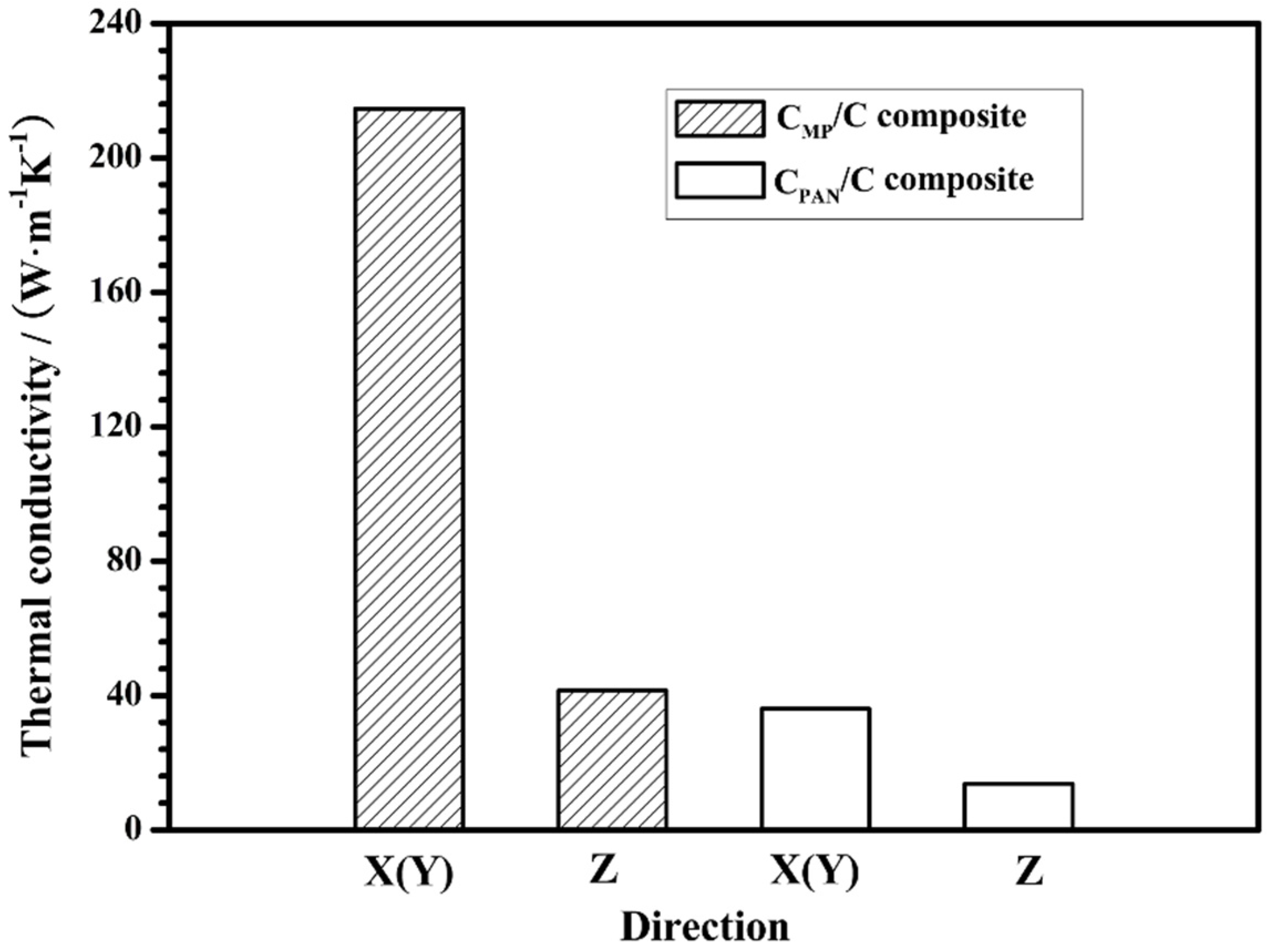
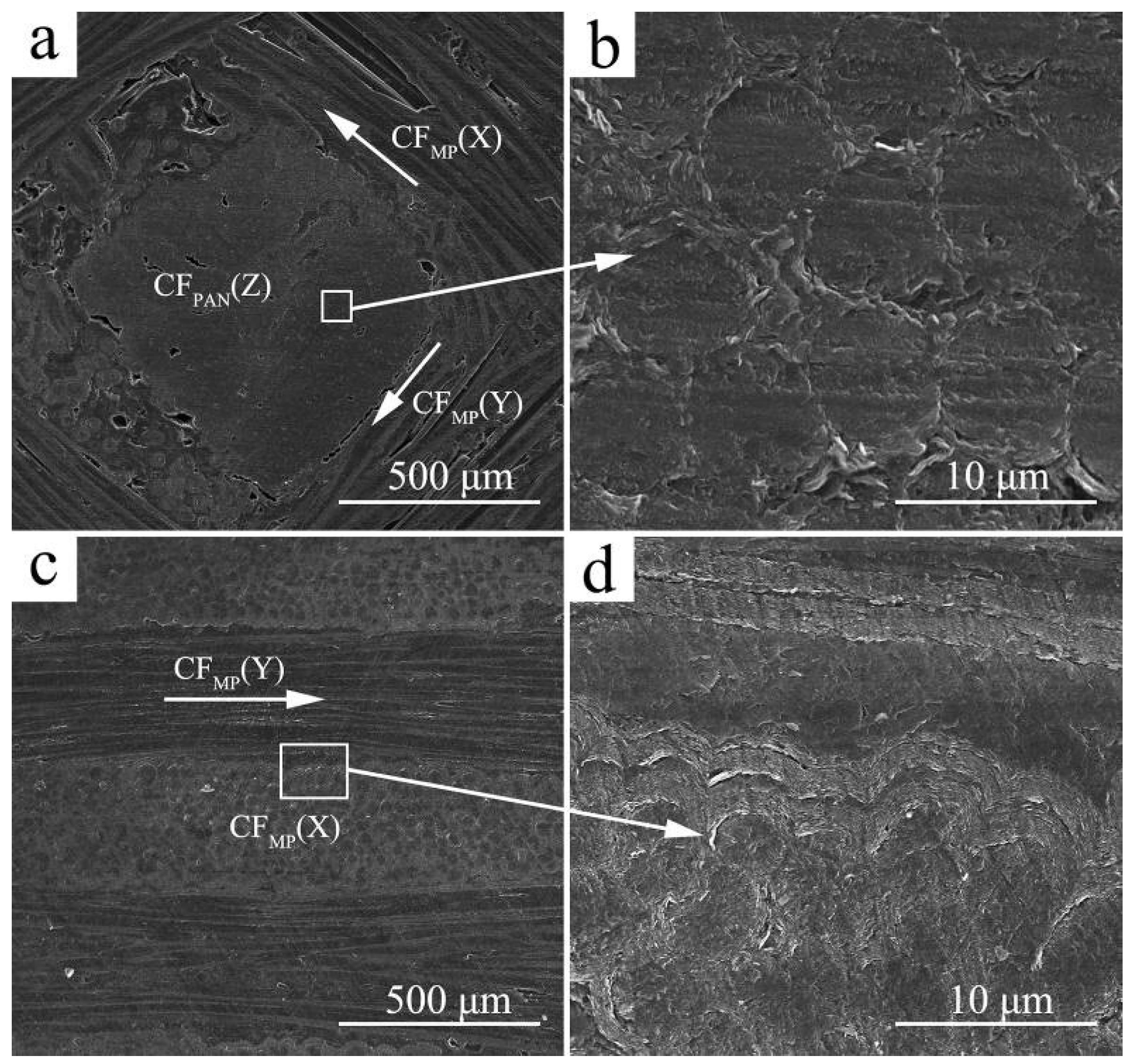
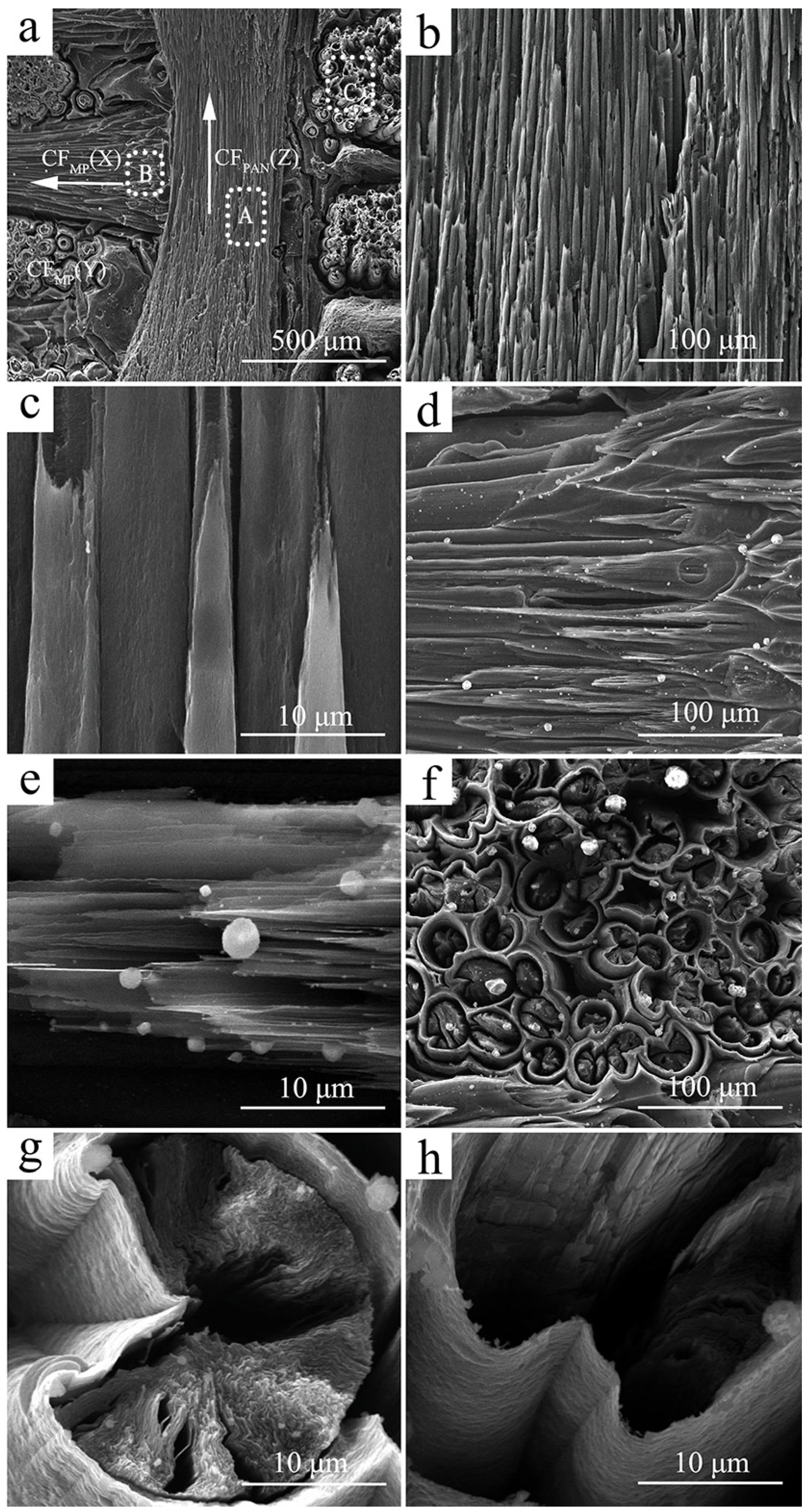
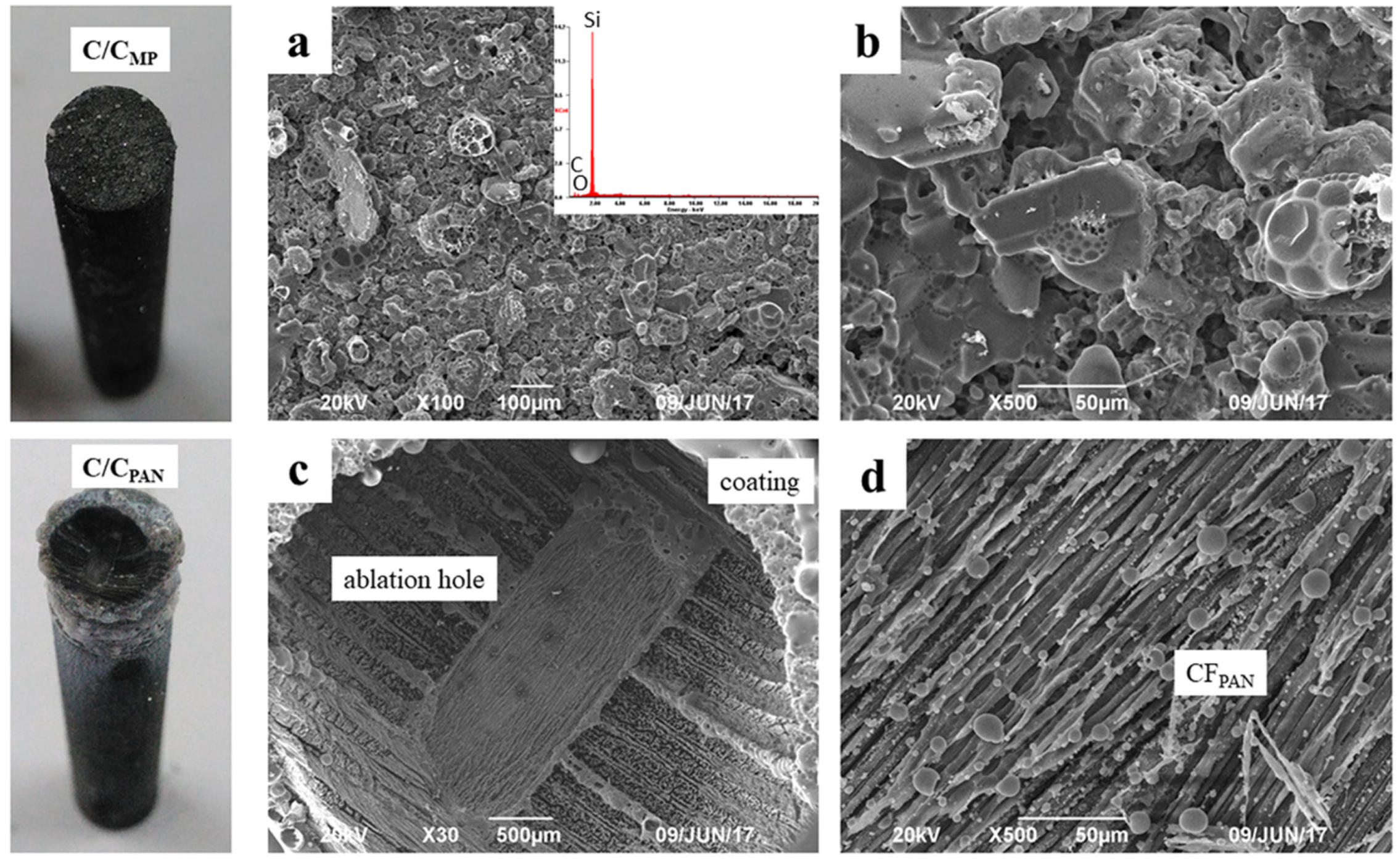
3.1. Microstructure of the Composites

The room-temperature thermal diffusion of the CMP/C composite is closely related to the composition, structure, and arrangement orientation of the carbon fibers and carbon matrix. The room-temperature thermal conductivity of the homemade CMP/C and CPAN/C composites is shown in Figure 2. It is known that the orientation and size of the graphite layer play important roles in the thermal conductivity of carbon fibers. The homemade CFMP had a larger graphite crystallite size, higher preferred orientation degree along the axis, and fewer crystallite defects, so it had higher thermal conductivity than CFPAN. The thermal conductivity of CFMP and the CFPAN is about 700 W·m−1·K−1 and 10 W·m−1·K−1, respectively (Table 1). Figure 2 shows that the thermal conductivity of the CMP/C composite (218.2 W·m−1·K−1) is evidently higher in the X and Y directions than that of the CPAN/C composite (36.1 W·m−1·K−1). It is speculated that the CMP/C composite can transfer heat from the hot side to the cool side more efficiently than the CPAN/C during ablation in the X or Y direction. In addition, because CFMP in the X (Y) direction has higher thermal conductivity and a higher volume fraction than CFPAN in the Z direction (Table 1), the thermal conductivity of the CMP/C composite in the X (Y) direction is higher than that in the Z direction.
Figure 3 shows the microstructure of the CMP/C composite. It can be seen that the CMP/C composite contains a small amount of cracks, voids, and debonded fiber/matrix interfaces. However, the composite is almost compact after densification (Figure 3a). Figure 3b shows that the round-shaped CFPAN in the Z direction is coated with PyC. The thickness of the PyC layer in CFPAN is less than that of the CFMP due to smaller gaps in CFPAN. The arrows in Figure 3a,c indicate the direction of the CFMP bundle in the composite. Compared to CFPAN, with thermal conductivity of about 10 W·m−1·K−1, it is evident that CFMP has higher thermal conductivity, reaching to above 700 W·m−1·K−1, which can contribute to the highly oriented graphitic structure along the fiber axis, larger crystal size, and more perfect crystallinity of CFMP [13]. Thus, the CMP/C composite has higher thermal conductivity in the X (Y) direction. High-magnification images indicate good interface bonding between PyC and CFMP, and resin carbon can also be found in the gaps among the PyC layers.
To further understand the influence of the microstructure of CMP/C composite on its ablation behavior, its fracture morphology was investigated (as shown in Figure 4). The location of this particular fracture in Figure 4 refers to the region of the dashed white lines in Figure 3c. Carbon fiber pull-out and interface debonding can be observed after rupture failure of the CMP/C composite (Figure 4a). It is interesting to find that the open wedge crack texture of the round-shaped CFMP is observed in the CMP/C composite (Figure 4b). It is reported that the linear domain units in CFMP induced circumferential shrinkage at the spinning and further heat-treatment steps, leading to the formation of the open crack [13,25]. Figure 4c indicates that CFMP is composed of a highly graphitic flat-layered structure radially oriented in the transverse section. The thermal conductivity of the carbon materials can be calculated according to the following formula:
λ = 1/3CνL
where λ is the thermal conductivity, ν is the propagation velocity of the phonon, and L is the free path of the phonon. CFMP has well-developed graphene sheets and a highly preferentially oriented crystal structure along the longitudinal and radial directions, which can provide fast thermal diffusion in phonon heat conduction. After graphitization, the layered structure of PyC is also formed (Figure 4d). Because the diameter of CFMP is larger and the gas precursor has a larger diffusion space in the preform during the CVI process, the PyC layer around CFMP is thicker than that around CFPAN.

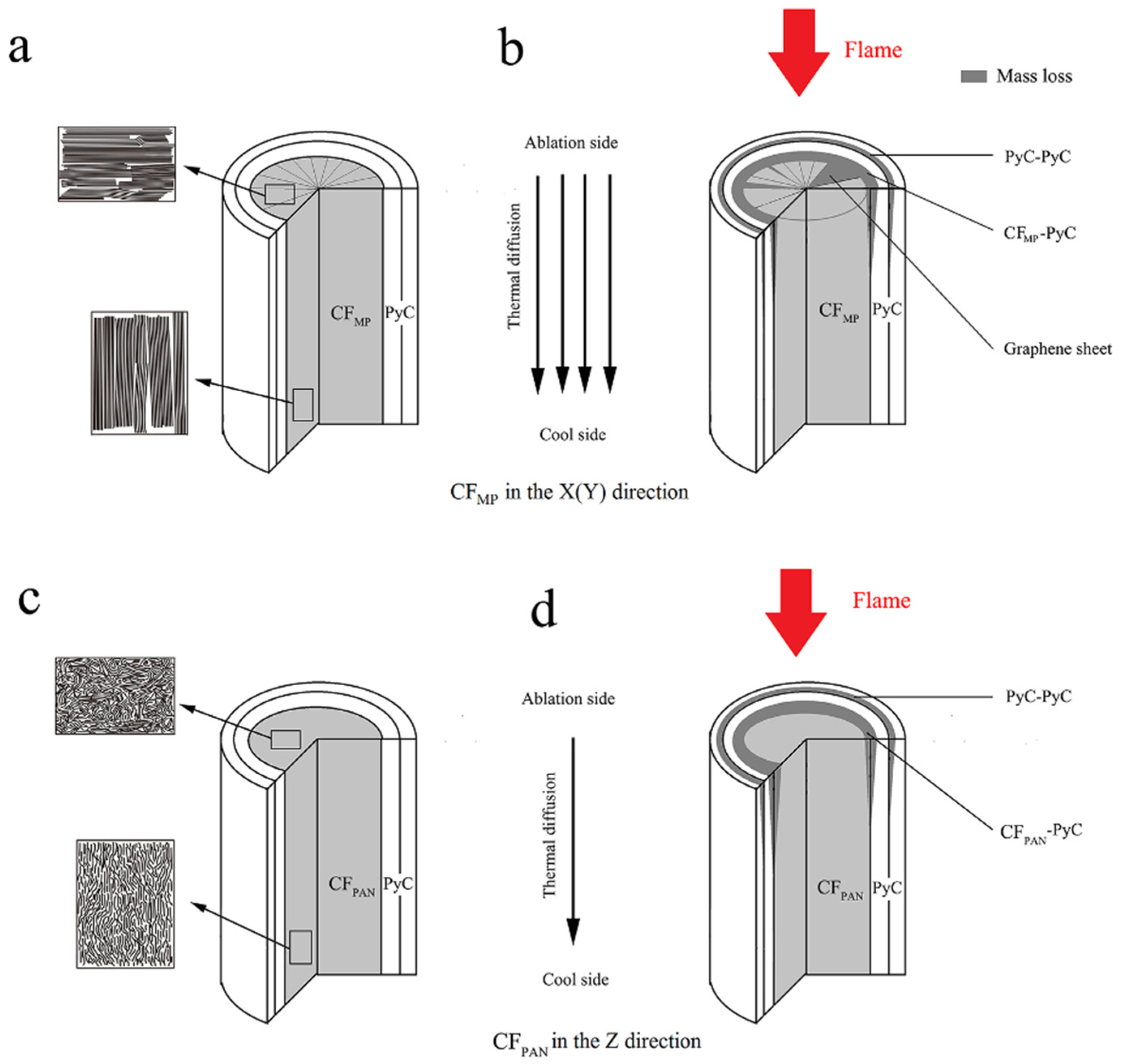
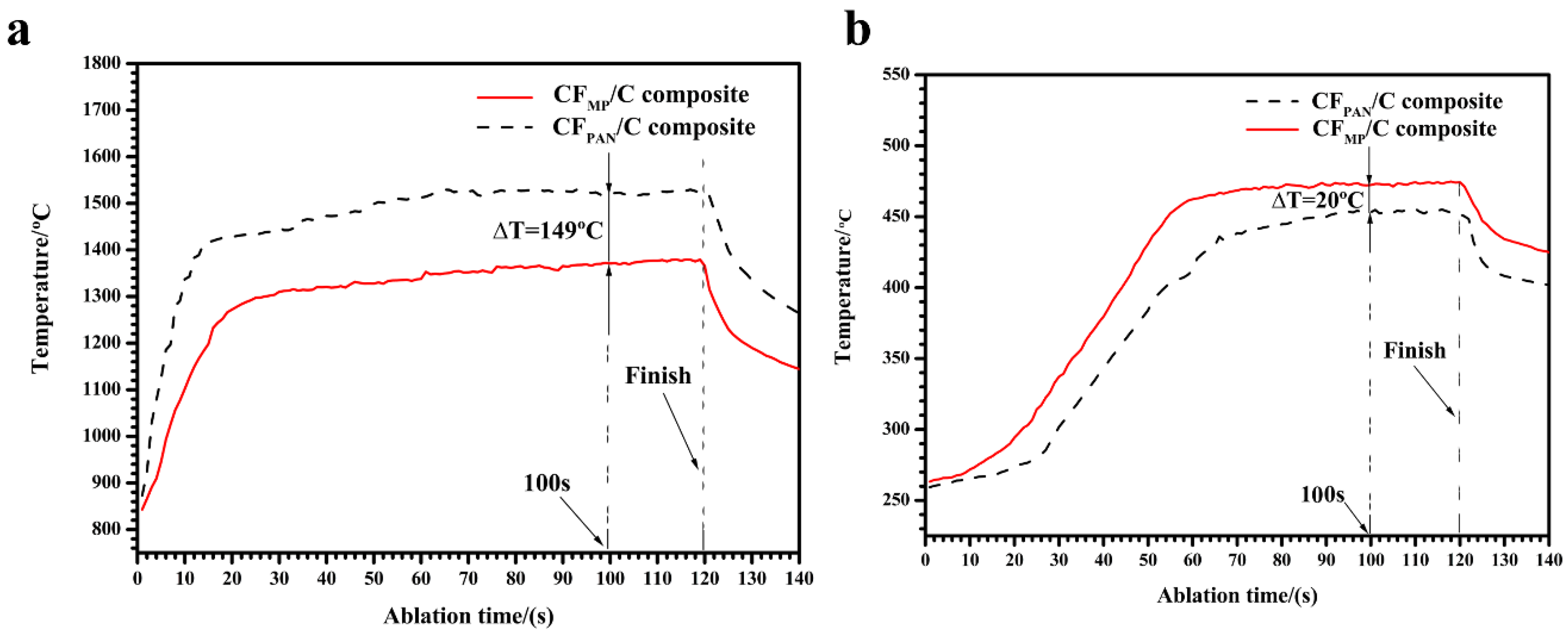
3.2. Ablation Behavior of CMP/C Composite

Figure 5 shows SEM images of the CMP/C composite (X–Z plane) after ablation. The ablated surface exhibits a rough and porous morphology and is mainly composed of ablated carbon fiber and matrix. It can be seen that both CFMP in the X (Y) direction and CFPAN in the Z direction are ablated (Figure 5a), but they show different ablation characteristics. CFPAN becomes needle-shaped after ablation (Figure 5b), which has been reported by many studies [24,25,26]. Because CFPAN has a turbostratic structure with physical entanglements and covalent cross-links, its cross-section after ablation looks like a homogeneous structure (Figure 5c) [15,16]. No peeling of the graphene sheet is observed. Compared to CFPAN, CFMP shows a wedge shape after ablation (Figure 5d). The layered structure in the fiber axis direction is formed after ablation, as shown in Figure 5e, suggesting that the mass loss preferentially takes place at the edges of layers or among layers because of the radial texture of CFMP. Figure 5f exhibits the ablated morphology of CFMP in the X direction, showing that the matrix (PyC) around the fiber bundles is eroded and forms a shell shape, and then is stripped off by the plasma flame. Before ablation, the boundary inside the carbon matrices and the CF/PyC interface presents good compatibility, and there is no PyC matrix microcracking or obvious interfacial debonding (Figure 3d). However, after ablation, many gaps or cracks are formed in the PyC matrix, the CF bundle, and the interface between them (Figure 5h). These indicate that ablation and oxidation begin at the CF/PyC interface and the boundary inside the PyC matrix, which are much easier to oxidize than the PyC matrix because of the more active sites in carbon nets. It is noted that many ablated defects, such as gaps or cracks, are also formed in the radial direction of CFMP (Figure 5g).
In order to better analyze the ablation behavior of CMP/C composite, we performed an oxidation test (Figure 6). It is observed that oxidation preferentially occurs at the CF/PyC interface, which is similar to ablation. When oxygen diffuses from the outer to the inner part of the CMP/C composite, the CF/PyC interface and boundary inside the matrix oxidize much more easily than the PyC matrix because there are more active sites in carbon nets (Figure 6a). The cross-section of CFMP after the oxidation test shows a more homogeneous morphology compared to the ablation test (shown in Figure 5g). Many small holes formed by oxidation can be observed in Figure 6b. The highly conductive CFMP in this study has a radial structure and weaker bonding among the highly oriented graphene layers. It can be speculated that the carbon atoms at these active sites may preferentially react with oxygen, leading to the radial carbon fragments formed by oxidation being easily stripped away from the CFMP (Figure 5g). Figure 6c shows the oxidation characteristics in the length direction of CFMP. Many slits are observed after oxidation, which can provide oxygen diffusion paths in the CFMP during oxidation. Figure 6d shows the oxidation characteristics in the carbon matrix. It can be seen that the PyC/PyC interface is more easily oxidized than the PyC itself. Slits are formed in the PyC/PyC interface, and some small holes are observed on the surface of the PyC matrix, indicating that the PyC/PyC interface presents higher chemical reactivity than the PyC matrix itself during oxidation. In addition, the oxidation and ablation tests showed that a thermal protective coating is necessary to prevent the CMP/C composite from being damaged in the oxygen atmosphere.
The ablation behavior of the CMP/C composite is mainly influenced by the oxidation reaction and the mechanical scouring caused by the plasma flame. The ablation behavior can be explained as follows (Figure 7): On the one hand, the oxidation reaction of the CMP/C composite refers to the heterogeneous reaction between the oxygen and the carbon phase, including carbon fiber and carbon matrix. The CF/PyC and PyC/PyC interfaces are preferentially oxidized and damaged due to the cracks and debonding defects. The PyC matrices around the CF bundle are burned into a shell shape, while the PyC matrices among the ablated CF are burned off. On the other hand, CFMP and CFPAN exhibit different ablation behaviors due to their different structural characteristics. CFPAN, with physical entanglements and covalent cross-links of turbostratic structure, becomes needle-shaped after ablation (Figure 5b). Compared to the homogeneous ablated structure of CFPAN, CFMP—with a highly preferentially oriented crystal structure—shows a wedge shape after ablation. The carbon phases in or between the edges of the layers of the highly graphitic flat-layered structure are more easily oxidized and stripped away from the CFMP during ablation. Therefore, the mass loss is observed in the radial direction.

3.3. Ablation Behavior of SiC-Coated CMP/C Composite

In order to further optimize the ablation resistance of the CMP/C composite, SiC coating was fabricated on the surface of samples by CVR (Figure 8). Figure 8b,c shows SEM images of the surface and cross-section of the coatings after CVR. The SiC coating surface seems to be coarse and rubble-like before ablation. The XRD pattern (Figure 8b) indicates that the coating is composed of β-SiC, which has three obvious characteristic peaks at 35.7°, 60.1°, and 71.8° ((111), (220), and (311), respectively, in a Face-Centered Cubic lattice). Figure 8c shows that the thickness of the SiC coating is about 50–80 μm, and there is no obvious crystal boundary in the cross-section (Figure 8c).
Photographs of the composites after 120 s of ablation are shown in Figure 9. The coating in the ablation center of CMP/C composite was not destroyed after ablation. The SiC grains were covered with a glass layer, which was identified as being SiO2 by EDS results (Figure 9a). It is worth noting that the ablation temperature (2300 °C) exceeded the boiling point of SiO2, but the SiC was not evidently corroded during ablation; only a few pitting corrosion features were observed on the coating surface. In comparison, coating in the ablation center of CMP/C composite was stripped off and the carbon fibers were ablated. Although some ceramic oxide residues were observed on the surface, they could not prevent the carbon phase from erosion. Table 2 shows the ablation rates of the CPAN/C and CMP/C composites with and without SiC coating. It can be concluded that without SiC coating, both composites show similar ablation rates during the test because the carbon phases are more easily oxidized and then stripped from the composites. Thermal conductivity does not have an obvious effect on the thermal protection. However, the SiC-coated CMP/C composite shows better ablation resistance than the SiC-coated CPAN/C composite after a 120 s ablation test. The mass and linear ablation rates of the SiC-coated CPAN/C composite are 13.57 μm·s−1 and 1.44 mg·(cm−2·s−1), respectively, and those of the SiC-coated CMP/C composite are only 0.52 μm·s−1 and 0.19 mg·(cm−2·s−1), respectively. Thermal conductivity is believed to play a significant role in decreasing the hot-side temperature and protecting the SiC coating from corrosion by the flame.
Figure 10a shows the surface temperature curves of the CMP/C and CPAN/C composites. It shows that the thermal conductivity of the composite has an influence on its surface temperature, because the composite with higher thermal conductivity allows more heat to be conducted from heating zones (sample surface) to colder zones (sample back), and then be dissipated. It can be seen from Figure 10a that the surface temperature of the CMP/C composite is about 1370 °C at 100 s, which is lower than the flame temperature (over 2300 °C) due to its high emissivity and thermal conductivity. The surface temperature of the CPAN/C composite increases rapidly to about 1427 °C at 20 s, whereas that of the CMP/C composite increases more slowly. After 100 s of ablation, the surface temperature of the CMP/C composite is 149 °C lower than that of the CPAN/C composite, indicating that CFMP can effectively dissipate heat away from the hot side (ablation center) to the relatively cool side (sample back). It is believed that CFMP is composed of a highly preferentially oriented crystal structure in the longitudinal direction, which can provide fast thermal diffusion in phonon heat conduction. The straight and continuous CFMP can effectively decrease the surface temperature by rapidly transferring the heat to the back side, and then radiate the heat around the environment. Because the thermal conductivity of the CMP/C composite (218.2 W·m−1·K−1) is much higher than that of the CPAN/C composite (36.1 W·m−1·K−1) along the ablation direction (Figure 1 and Figure 2), it can be concluded that more heat in the ablation center of the CMP/C composite is dissipated away under the same conditions. Figure 10b shows that the temperature of the CMP/C composite on the cool side (sample back) increases more than that of the CPAN/C composite. At 100 s, the cool-side temperature of the CMP/C composite is 20 °C higher than that of the CPAN/C composite. The result also indicates that more heat can be conducted from the ablation center (hot side) to the sample back (cool side) when CMP with high conductivity is used in the composite. Based on this analysis, it can be concluded that the high conductivity of the CMP/C composite (CFMP) plays a positive role in its ablation resistance.

4. Conclusions

The prepared CMP/C composite has higher thermal conductivity in the X and Y directions. After the ablation test, CFPAN becomes needle-shaped, while CFMP shows a wedge shape. The fiber/matrix and matrix/matrix interfaces are preferentially oxidized and damaged during ablation. If there is no SiC coating, the CMP/C and CPAN/C composites show similar ablation rates during ablation. After being coated by SiC coating, thermal conductivity is believed to play a significant role in decreasing the hot-side temperature and protecting the coating from corrosion by the flame. The SiC-coated CMP/C composite shows better ablation resistance than the SiC-coated CPAN/C composite after a 120 s ablation test. The mass and linear ablation rates of the SiC-coated CMP/C composite are only 0.52 μm·s−1 and 0.19 mg·cm−2·s−1, respectively. The result indicates that the CMP/C composite can effectively decrease the hot side temperature by rapidly conducting heat to the cool side, which can improve its ablation resistance.
This work is focused on the microstructural features and ablation properties of CMP/C composite. Actually, the finite element model is believed to be an effective method to analyze its thermal conduction mechanism and ablation behavior. Further research on this advanced computational method is ongoing in this program.

Author Contributions

Conceptualization, D.H. and X.L.; Methodology, D.H. and B.L.; Validation, H.W., C.Y., P.Y. and J.Y.; Investigation, D.H. and C.Y.; Resources, X.L. and J.L.; Data Curation, D.H. and H.W.; Writing—Original Draft Preparation, D.H. and C.Y.; Writing—Review and Editing, D.H. and X.L.; Project Administration, X.L. and J.L.

Funding

This research was funded by The Innovation and Entrepreneurship Investment Project of Hunan Provincial Science and Technology Department (grant number: 2018GK5065), Research and Development Plan in Key Areas of Hunan Province (grant number: 2019GK2021), National Natural Science Foundation of China (grant number: 51372177, 51702094), and the Natural Science Foundation for Young Scientists of Hunan Province (2017JJ3014).

Conflicts of Interest

The authors declare no conflict of interest. The funders had no role in the design of the study; in the collection, analyses, or interpretation of data; in the writing of the manuscript, or in the decision to publish the results.

Abbreviations

C/C compositeThe carbon-fiber-reinforced carbon matrix (C/C) composite
CFcarbon fiber
PANpolyacrylonitrile
CFPANPAN-based carbon fiber
CFMPmesophase pitch-based carbon fiber
CMP/C compositeC/C composite prepared using the CFMP in the X (Y) direction and the CFPAN in the Z direction in this study
CPAN/C compositeC/C composite prepared using the CFPAN in all directions
CVIchemical vapor infiltration
PIPpolymer infiltration and pyrolysis
CVRchemical vapor reaction

References

  1. Sheehan, J.E.; Buesking, K.W.; Sullivan, B.J. Carbon-Carbon Composites. Annu. Rev. Mater. Sci. 1994, 24, 19–44. [Google Scholar] [CrossRef]
  2. Fitzer, E. The future of carbon-carbon composites. Carbon 1987, 25, 163–190. [Google Scholar] [CrossRef]
  3. Zhang, X.; Li, X.; Yuan, G.; Dong, Z.; Ma, G.; Rand, B. Large diameter pitch-based graphite fiber reinforced unidirectional carbon/carbon composites with high thermal conductivity densified by chemical vapor infiltration. Carbon 2017, 114, 59–69. [Google Scholar] [CrossRef]
  4. Manocha, L.M.; Warrier, A.; Manocha, S.; Sathiyamoorthy, D.; Banerjee, S. Thermophysical properties of densified pitch based carbon/carbon materials—I. Unidirectional composites. Carbon 2006, 44, 480–487. [Google Scholar] [CrossRef]
  5. Li, T.; Xu, Z.; Hu, Z.; Yang, X. Application of a high thermal conductive C/C composite in a heat-redistribution thermal protection system. Carbon 2010, 48, 924–925. [Google Scholar] [CrossRef]
  6. Lachaud, J.; Aspa, Y.; Vignoles, G.L. Analytical modeling of the steady state ablation of a 3D C/C composite. Int. J. Heat Mass Transf. 2008, 51, 2614–2627. [Google Scholar] [CrossRef] [Green Version]
  7. Lee, K.J.; Chen, Z.Y. Microstructure study of PAN–pitch-based carbon–carbon composite. Mater. Chem. Phys. 2003, 82, 428–434. [Google Scholar] [CrossRef]
  8. Baxter, R.I.; Rawlings, R.D.; Iwashita, N.; Sawada, Y. Effect of chemical vapor infiltration on erosion and thermal properties of porous carbon/carbon composite thermal insulation. Carbon 1999, 38, 441–449. [Google Scholar] [CrossRef]
  9. Kumar, S.; Kushwaha, J.; Mondal, S.; Kumar, A.; Jain, R.K.; Devi, R.G. Fabrication and ablation testing of 4D C/C composite at 10MW/m2 heat flux under a plasma arc heater. Mater. Sci. Eng. A 2013, 566, 102–111. [Google Scholar] [CrossRef]
  10. Levet, C.; Helber, B.; Couzi, J.; Mathiaud, J.; Gouriet, J.B.; Chazot, O.; Vignoles, G.L. Microstructure and gas-surface interaction studies of a 3D carbon/carbon composite in atmospheric entry plasma. Carbon 2017, 114, 84–97. [Google Scholar] [CrossRef]
  11. Newcomb, B.A. Processing, structure, and properties of carbon fibers. Compos. Part A Appl. Sci. Manuf. 2016, 91, 262–282. [Google Scholar] [CrossRef]
  12. Emmerich, F.G. Young’s modulus, thermal conductivity, electrical resistivity and coefficient of thermal expansion of mesophase pitch-based carbon fibers. Carbon 2014, 79, 274–293. [Google Scholar] [CrossRef]
  13. Mochida, I.; Yoon, S.H.; Takano, N.; Fortin, F.; Korai, Y.; Yokogawa, K. Microstructure of mesophase pitch-based carbon fiber and its control. Carbon 1996, 34, 941–956. [Google Scholar] [CrossRef]
  14. Wu, S.; Liu, Y.; Ge, Y.; Ran, L.; Peng, K.; Yi, M. Surface structures of PAN-based carbon fibers and their influences on the interface formation and mechanical properties of carbon-carbon composites. Compos. Part A Appl. Sci. Manuf. 2016, 90, 480–488. [Google Scholar] [CrossRef]
  15. Paiva, M.C.; Bernardo, C.A.; Nardin, M. Mechanical, surface and interfacial characterisation of pitch and PAN-based carbon fibers. Carbon 2000, 38, 1323–1337. [Google Scholar] [CrossRef]
  16. Qin, X.; Lu, Y.; Xiao, H.; Wen, Y.; Yu, T. A comparison of the effect of graphitization on microstructures and properties of polyacrylonitrile and mesophase pitch-based carbon fibers. Carbon 2012, 50, 4459–4469. [Google Scholar] [CrossRef]
  17. Yuan, G.; Li, X.; Dong, Z.; Xiong, X.; Rand, B.; Cui, Z.; Cong, Y.; Zhang, J.; Li, Y.; Zhang, Z.; et al. Pitch-based ribbon-shaped carbon-fiber-reinforced one-dimensional carbon/carbon composites with ultrahigh thermal conductivity. Carbon 2014, 68, 413–425. [Google Scholar] [CrossRef] [Green Version]
  18. Adams, P.M.; Katzman, H.A.; Rellick, G.S.; Stupian, G.W. Characterization of high thermal conductivity carbon fibers and a self-reinforced graphite panel. Carbon 1988, 36, 233–245. [Google Scholar] [CrossRef]
  19. Luo, R.; Liu, T.; Li, J.; Zhang, H.; Chen, Z.; Tian, G. Thermophysical properties of carbon/carbon composites and physical mechanism of thermal expansion and thermal conductivity. Carbon 2004, 42, 2887–2895. [Google Scholar] [CrossRef]
  20. Baxter, R.I.; Iwashita, N.; Sawada, Y. Effect of halogen purification and heat treatment on thermal conductivity of high porosity carbon/carbon composite thermal insulation. J. Mater. Sci. 2000, 35, 2749–2756. [Google Scholar] [CrossRef]
  21. Klett, J.W.; Ervin, V.J.; Edie, D.D. Finite-element modeling of heat transfer in carbon/carbon composites. Compos. Sci. Technol. 1999, 59, 593–607. [Google Scholar] [CrossRef]
  22. Ai, S.G.; He, R.J.; Pei, Y. M A numerical study on the thermal conductivity of 3d woven c/c composites at high temperature. Appl. Compos. Mater. 2015, 22, 823–835. [Google Scholar]
  23. Li, K.; Shen, X.; Li, H.; Zhang, S.; Feng, T.; Zhang, L. Ablation of the carbon/carbon composite nozzle-throats in a small solid rocket motor. Carbon 2011, 49, 1208–1215. [Google Scholar] [CrossRef]
  24. Li, H.; Yao, X.; Zhang, Y.; Li, K.; Guo, L.; Liu, L. Effect of heat flux on ablation behaviour and mechanism of C/C-ZrB2-SiC composite under oxyacetylene torch flame. Corros. Sci. 2013, 74, 265–270. [Google Scholar] [CrossRef]
  25. Yoon, S.; Korai, Y.; Mochida, I. Crack formation in mesophase pitch-based carbon fibres: Part II Detailed structure of pitch-based carbon fibres with some types of open cracks. J. Mater. Sci. 1997, 32, 2759–2769. [Google Scholar] [CrossRef]
  26. Li, C.Y.; Li, K.Z.; Li, H.J.; Ouyang, H.B.; Zhang, Y.L.; Guo, L.J. Ablation resistance and thermal conductivity of carbon/carbon composites containing hafnium carbide. Corros. Sci. 2013, 75, 169–175. [Google Scholar] [CrossRef]
Figure 1. (a) Preparation process and (b) ablation test of CMP/C composite. CVI, chemical vapor infiltration; PIP, polymer infiltration and pyrolysis; CMP, mesophase pitch-based carbon fiber.
Materials 12 02723 g001
Figure 2. Thermal conductivity of CMP/C and CPAN/C composites. CPAN, polyacrylonitrile (PAN)-based carbon fiber.
Materials 12 02723 g002
Figure 3. Microstructure of CMP/C composite: (a) X–Y plane; (b) CFPAN in the Z direction; (c) Y–Z plane; (d) high-magnification image.
Materials 12 02723 g003
Figure 4. SEM images of fracture section of CMP/C composite: (a) low-magnification image; (bd) high-magnification images of PyC-coated CFMP, highly preferentially oriented crystal structure in CFMP (c) and PyC (d). The white arrows show the regions at high magnification.
Materials 12 02723 g004
Figure 5. SEM images of CMP/C composite after ablation: (a) microstructure in the ablation center; (b) low-magnification image of CFPAN in the Z direction (region A in (a)); (c) high-magnification image of CFPAN in the Z direction (region A in (a)); (d) low-magnification image of CFMP in the Y direction (region B in (a)); (e) high-magnification image of CFMP in the Y direction (region B in (a)); (f) low-magnification image of CFMP in the X direction (region C in (a)); (g) high-magnification image of CFMP in the X direction (region C in (a)); (h) interface between PyC layers after ablation (region C in (a)). The white arrows in (a) show the directions of the CFPAN and CFMP.
Materials 12 02723 g005
Figure 6. Microstructure of CMP/C composite after oxidation: (a) microstructure of the Y–Z plane; (b) CFMP in the X direction; (c) CFMP in the Y direction; (d) interface between PyC layers.
Materials 12 02723 g006
Figure 7. Ablation behavior of CMP/C composite in different directions: (a) CFMP in the X (Y) direction before ablation; (b) CFMP in the X(Y) direction after ablation; (c) CFPAN in the Z direction before ablation; (d) CFPAN in the Z direction after ablation.
Materials 12 02723 g007
Figure 8. Microstructure of SiC coating: (a) photos of SiC-coated samples before and after ablation tests; (b) SEM image of the surface of the coating; (c) SEM image of the cross-section of the coating.
Materials 12 02723 g008
Figure 9. Microstructure of samples after ablation for 120 s: (a) low-magnification SEM image of ablation center on surface of SiC-coated CMP/C composite; (b) high-magnification image of (a); (c) low-magnification SEM image of the ablation center on the surface of SiC-coated CPAN/C composite; (d) high-magnification image of (c).
Materials 12 02723 g009
Figure 10. Temperature curves of samples at (a) ablation center and (b) cool side under the same ablation conditions.
Materials 12 02723 g010
Table 1. Characteristics of carbon fiber in CMP/C composite. CFMP, mesophase pitch-based carbon fiber; CFPAN, polyacrylonitrile carbon fiber.
Thermal Conductivity (W·m−1·K−1)Volume Fraction (%)Direction
CFMP≥70036X, Y
CFPAN~108–10Z
Table 2. Ablation rates of samples after ablation under air atmosphere for 120 s.
SampleLinear Ablation Rate (μm·s−1)Mass Ablation Rate (mg·cm−2·s−1)
SiC-coated CMP/C0.520.19
SiC-coated CPAN/C13.571.44
CMP/C28.2112.24
CPAN/C26.4511.31

