Investigation of Cutting Force in Longitudinal-Torsional Ultrasonic-Assisted Milling of Ti-6Al-4V


School of Mechanical and Power Engineering, Henan Polytechnic University, Jiaozuo 454000, China
*
Authors to whom correspondence should be addressed.
Materials 2019, 12(12), 1955; https://doi.org/10.3390/ma12121955
Submission received: 31 May 2019
/
Revised: 13 June 2019
/
Accepted: 14 June 2019
/
Published: 17 June 2019
Abstract
:In this study, we propose a longitudinal-torsion ultrasonic-assisted milling (LTUM) machining method for difficult-to-cut materials—such as titanium alloy—in order to realize anti-fatigue manufacturing. In addition, a theoretical prediction model of cutting force is established. To achieve this, we used the cutting edge trajectory of LTUM to reveal the difference in trajectory between LTUM and traditional milling (TM). Then, an undeformed chip thickness (UCT) model of LTUM was constructed. From this, the cutting force model was able to be established. A series of experiments were subsequently carried out to verify this LTUM cutting force model. Based on the established model, the influence of several parameters on cutting force was analyzed. The results showed that the established theoretical model of cutting force was in agreement with the experimental results, and that, compared to TM, the cutting force was lower in LTUM. Specifically, the cutting force in the feed direction, Fx, decreased by 24.8%, while the cutting force in the width of cut direction Fy, decreased by 29.9%.
1. Introduction
Titanium alloy has a number of excellent properties, such as corrosion resistance, high strength and good heat resistance, and is widely used in medical, aerospace and other fields [1]. It is considered a typical difficult-to-cut material due to its chemical, physical and mechanical properties; for instance, the cutting temperature and cutting force is high, the friction force is large, and tool wear is serious [2,3]. Currently, a number of difficulties and challenges still exist in the traditional processing technologies (turning, grinding and milling, etc.) for such difficult-to-cut materials, particularly while maintaining high quality, high efficiency and low cost [4,5].
Ultrasonic-assisted machining technology is a non-traditional machining technology. It applies vibrations of an ultrasonic frequency to the tool or workpiece along a certain direction. Compared with traditional cutting technologies, such as turning, grinding and milling, ultrasonic machining technology has obvious technological advantages, including a small cutting force, low cutting temperature, high surface quality and high machining precision [6,7,8].
Ultrasonic vibration-assisted milling technology started relatively recently, with its literature mainly focusing on the early 21st century. At present, research on ultrasonic vibration-assisted milling is in the developing stages. In 2006, Chern and Chang [9] studied the machinability of ultrasonic vibration-assisted micro-milling of aluminum alloy, and found that vibration milling meaningfully improved the surface quality. This was the first time that ultrasonic vibration was introduced into milling. Shen et al. [10] carried out a detailed study on ultrasonic vibration-assisted milling of aluminum alloy. They found that ultrasonic vibration-assisted milling transformed the continuous cutting process into discontinuous differential cutting. In addition, the cutting process produced a cutting force similar to that of the pulse type, effectively reducing the average cutting force. Zarchi et al. [11] studied ultrasonic vibration-assisted milling of AISI 420 stainless steel and found that for a small feed rate, it reduced the cutting force in up milling, while during a larger feed rate, it reduced the cutting force in down milling. Zhao et al. [12] investigated the cutting force differences between rotary ultrasonic machining and conventional diamond side grinding, drilling and face grinding on K9 glass, and found that rotary ultrasonic machining reduced the cutting force to a certain extent.
However, in one-dimensional ultrasonic-assisted machining, with the necessary high-frequency vibration of the tool, the tool flank generates extrusion friction with the machined surface. This is seriously harmful to the life of the tool and the machined surface quality [13,14], and limits further application of ultrasonic vibration cutting technology. On the contrary, in longitudinal-torsional ultrasonic vibration-assisted milling (LTUM), due to the cutting edge moving in three-dimensional space, extrusion friction between the tool flank and the machined surface is effectively avoided. In addition, the shear angle is increased and the average cutting force and cutting temperature in processing are (further) reduced [15,16], which is important in anti-fatigue manufacturing of high performance components.
An accurate prediction of cutting force is conducive to the evaluation of machine tool power, main bearing pressure, parts deformation, control of processing quality, and so on. At present, the most commonly used methods for predicting milling force are as follows: Micro-element model, finite element model, multiple regression analysis model and artificial neural network prediction model.
Liu et al. [17] conducted verified experiments and presented a mechanistic model for cutting force in rotary ultrasonic machining of brittle materials, and found that the model predicted cutting force with high precision. Zhang et al. [18] developed a mechanistic model to predict the cutting force in rotary ultrasonic drilling of brittle materials, showing that the model could be successfully applied to evaluate cutting force. Xiao et al. [19] developed a theoretical model of cutting force both in the axial and feed directions in rotary ultrasonic machining. Yuan et al. [20], Cong et al. [21], and Wang et al. [22] each presented a predictive model for cutting force, wherein their calculated results were subsequently verified by experimentation.
In the literature, there have been numerous valuable researches into cutting force; however, in terms of the outstanding advantages of LTUM (in particular, the tool as a vibration carrier), few of these investigations have been in relation to milling of difficult-to-cut materials, such as titanium alloys. Therefore, in the present work, in order to meet the compressive stress and anti-fatigue manufacturing requirements of titanium alloy Ti-6Al-4V, an LTUM machining method (with the tool as a vibration carrier) was developed. Models of the cutting edge trajectory and undeformed chip thickness (UCT) were also constructed. In addition, a cutting force model of LTUM was established and then verified through a series of experiments. Based on this established model, the influence of several parameters on cutting force was analyzed.
2. Materials and Methods
2.1. Trajectory Model of Cutting Edge in LTUM
The principles of LTUM are shown in Figure 1. The cutting edge trajectory employed in LTUM makes it very different to traditional milling (TM), as the trajectory used has a direct impact on the cutting force, as well as other processing procedures and results.
For TM, the cutting edge trajectory equation (Equation (1)) is as follows:
where vf is feed rate, Rt is tool radius, and n is spindle speed.
From this, an equation (Equation (2)) concerning the cutting edge trajectory for LTUM may be established:
where f is ultrasonic frequency, Al is longitudinal amplitude in LTUM, and ωn-t is the actual rotation angle of the tool, obtained from Equation (3).
where, ωl-t is torsional angle, obtained from Equation (4).
where, At is torsional amplitude and φl-t is the phase difference for the longitudinal-torsional vibration.
Based on Equations (1) and (2), the trajectories of the cutting edges in LTUM and TM are illustrated in Figure 2.
In Figure 2, A1, A2,…, An points represent the starting separation positions between the tool and workpiece, while B1, B2,…, Bn points represent the starting contact points, called the feature points. It can be seen that the cutting edge moves along the blue line in LTUM, and that the tool–workpiece undergoes periodic changes of separation-contact-separation with ultrasonic vibration. This caused a large difference from the cutting edge trajectory of TM (red line).
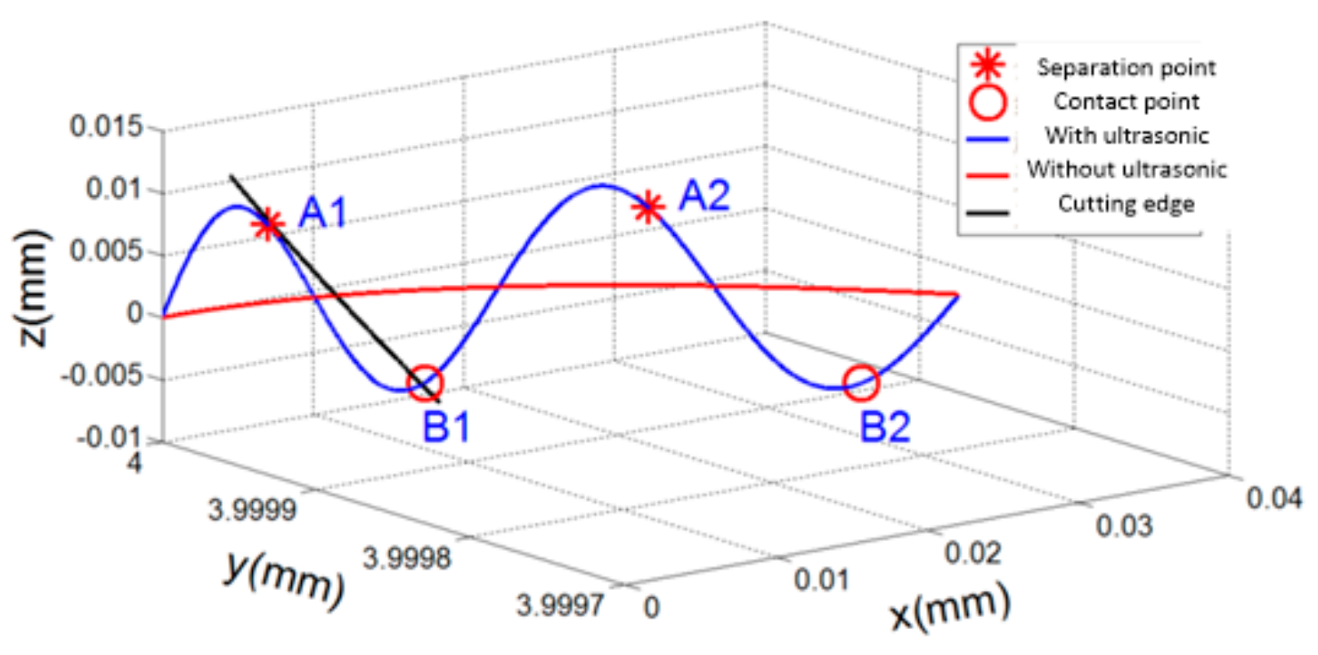
According to the solution model of feature points, the separation and contact points of LTUM were able to be calculated, as shown in Figure 3. In the figure, A1, A2, and A3 are the separation points between the tool and workpiece, and B1, B2 and B3 are the contact points. In the process, the cutting edge is separated from the workpiece from point A1 to point B1, and contacting the workpiece from point B1 to point A2.
Thus, we concluded that for LTUM, the tool and workpiece exhibit periodic separation, while at the same time perform a cutting edge motion in 3D space. This significantly avoids the extrusion friction between the tool flank and machined surface, thereby reducing the cutting force and improving the quality of the machined surface.
2.2. Undeformed Chip Thickness Model of LTUM
Undeformed chip thickness (UCT) greatly influences both the cutting force and machining results; however, compared with TM, UCT is more complicated in LTUM. As such, it is helpful to establish a UCT model of LTUM to reveal the mechanism of the cutting force.
As shown in Figure 1, a tool coordinate system was established, wherein the feed direction was represented by the x axis, the width of cut direction was represented by the y axis, the spindle axis was represented by the z axis, and the origin was set on the tool rotation center. From this, a UCT model could be established, as shown in Figure 4.
At any time, t, the position of the j-th teeth is given by the solid line in Figure 4. The angular displacement of the tool teeth and the Yt axis is expressed in Equation (5):
From this, UCT hj(t) at time t is equal to the distance between the position Q of the j-th teeth and the position P of the (j−1)-th teeth at the time (t−ṷj(t)), where ṷj(t) is the time delay between the j-th teeth and (j−1)-th teeth.
At time t, the Q point coordinate value may be expressed in Equation (6):
In Equation (6), is the coordinates of a moving coordinate system origin in the fixed coordinate system XOY, where is the coordinates of the tool center in the moving coordinate system.
At time (t−ṷj(t)), the point P coordinate may be calculated from Equation (7):
P point coordinate may also be calculated using Equation (8):
Obviously, Equations (7) and (8) are equal, therefore,
From Equations (7)–(10):
where
As a result, UCT may be calculated using Equation (13):
and
If the tool moves uniformly with feed rate, the UCT hj(t) is composed of a static cutting thickness hjs and a dynamic cutting thickness hjd. Thus:
In actual fact, for LTUM, the cutting edge trajectory is similar to sub-cycloid motion. The cutting edge generates sub-cycloid motion with a longer period of spindle rotation and a shorter period of ultrasonic vibration.
Thus, at time t, UCT hjlt(t) of LTUM is given by Equation (16):
2.3. Cutting Force Model of LTUM
On the basis of Merchant’s [23] cutting force model, we transformed LTUM into an oblique cutting model, as shown in Figure 5. The geometric relationship of this cutting force model is shown in Figure 6.
According to Ref. [24], the relationship between the chip flow direction angle and the inclination angle (helix angle) is:
where βsf is the friction angle and the direction of cutting speed and force is determined by ϕsn, ϕsi, θsn, θsi.
Then, the normal force Fn may be obtained using:
where Fx and Fy represent the cutting forces in the feed direction and the width of cut direction, respectively.
A non-linear cutting force model [25] is adopted. For any teeth, j, the instantaneous cutting forces are related to the UCT, as in Equation (21):
Then, Fx and Fy may be solved by applying Equation (22):
where is the window function. To judge whether or not the teeth are cutting in, Equation (23) is applied:
where Φst, Φex is the cutting-in and out angle.
From Equations (21)–(23), cutting force at any time is solved using Equation (24):
where Kt, Kr are cutting force coefficients, calculated by Equation (25):
3. Results
A series of verification experiments were carried out under LTUM to assess the matching attributes of the established cutting force model for LTUM.
3.1. Experimental Condition
As shown in Figure 7, longitudinal ultrasonic vibration was transmitted from an ultrasonic power supply to a transducer via a non-contact transmission device. The longitudinal vibration was then transformed into longitudinal-torsional vibration by a horn with spiral flutes, generating longitudinal-torsional vibration on the milling tool.
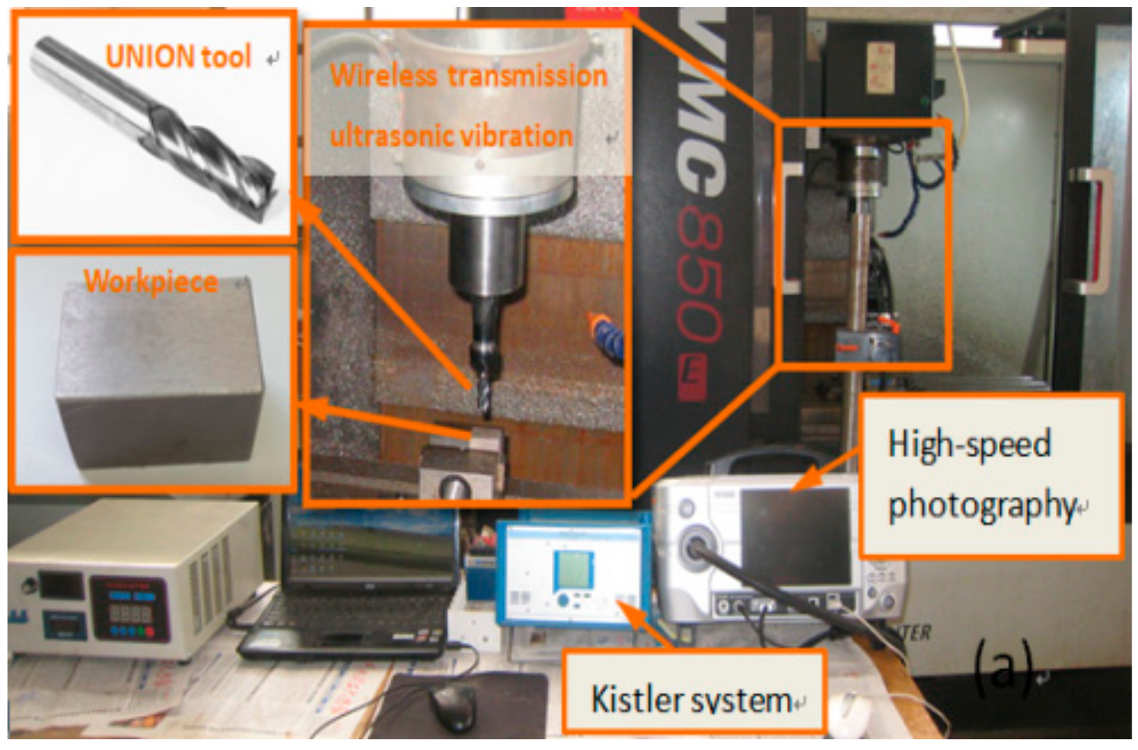
The side and down milling of Ti-6Al-4V was carried out on a machining center. The chemical composition of the workpiece material, Ti-6Al-4V was presented in Ref. [15]. The size of the rectangular workpiece used was 30 mm × 15 mm × 6 mm. The experimental equipment was composed of a Kistler dynamometer system (9257B, Winterthur, Switzerland), a self-developed wireless transmission longitudinal-torsion ultrasonic vibration assisted milling system, a high-speed photography camera and a computer. For the machining processing, a cemented carbide UNION tool (C-CES 10*25) was adopted. The experimental devices are shown in Figure 8.
3.2. Experimental Verification Results
In order to verify the established cutting force model, the calculated cutting force result was compared with the experimental result. This was carried out based on the cutting force direction exhibited in Figure 1.
The simulated result is shown in Figure 9a. The cutting force appeared to first increase and then decrease after reaching a peak value, resulting in a parabolic trend considered in accordance with a variation law of undeformed chip thickness. The cutting force was also found to periodically return to zero with the ultrasonic vibration, which was mainly caused by the tool–workpiece separation characteristics produced in LTUM.
The experimental result is shown in Figure 9b. Again, the cutting force was found to fluctuate periodically with the cutting-in and cutting-out of teeth; however, the result was different from the simulated findings as the cutting force did not return to zero. The reason for this is it is impossible to accurately measure the cutting force of each ultrasonic cycle, even when using a Kistler 9257B piezoelectric dynamometer (Winterthur, Switzerland), which is one of the most-advanced dynamometers in the world (with a sampling frequency of 10 kHz).
The simulated and experimental results were further compared, as shown in Figure 10. Figure 10a is a comparison of the cutting force for individual teeth (e.g., the area circled in red in Figure 9b), with the same processing parameters outlined in Figure 9. Figure 10b compares the model-predicted and experimental cutting force results under different parameters, wherein CS is the abbreviation for cutting speed, FpT is the feed per tooth, WoC is the width of cut, DoC is the depth of cut, LA is the longitudinal amplitude, and TA is the torsional amplitude. The relevant processing parameters for this comparison are provided in Table 1, Table 2 and Table 3. Although it was not possible to compare the cutting force of each ultrasonic cycle, the predicted result appeared to be in good agreement with the experimental result based on the whole view, suggesting that the established cutting force model worked well in such conditions.
Figure 11 shows a comparison of the cutting forces in TM and LTUM, wherein the processing parameters are listed in Table 1, Table 2 and Table 3 (for TM, the Table 3 data are set to 0). Compared with TM, the cutting forces were found to be lower in LTUM, with a 24.8% decrease in Fx and a 29.9% decrease in Fy. The reason for these results is the tool and workpiece separate periodically in LTUM due to ultrasonic vibration, causing the actual cutting time of LTUM to be less than that of TM. In addition, with the longitudinal and torsional ultrasonic vibration, the friction resistance between the chip and the tool is transformed into a beneficial cutting force, so that the cutting force is smaller than that of TM.
4. Discussion
4.1. Influence of Tool Geometry Parameters on Cutting Force
The geometric parameters of tools have a great influence on the cutting force and machining quality. However, it is difficult to evaluate the influence of tool geometry parameters on machining results by experimental methods. On the one hand, the cost is high and the efficiency is low; on the other hand, the choice of geometric parameters of the formed tool (especially a vertical milling tool) is limited, and the time and cost involved in tool parameter customization is high. By using theoretical simulations, the influence of tool geometry parameters on machining results can be analyzed economically and efficiently, providing another option for engineering applications.
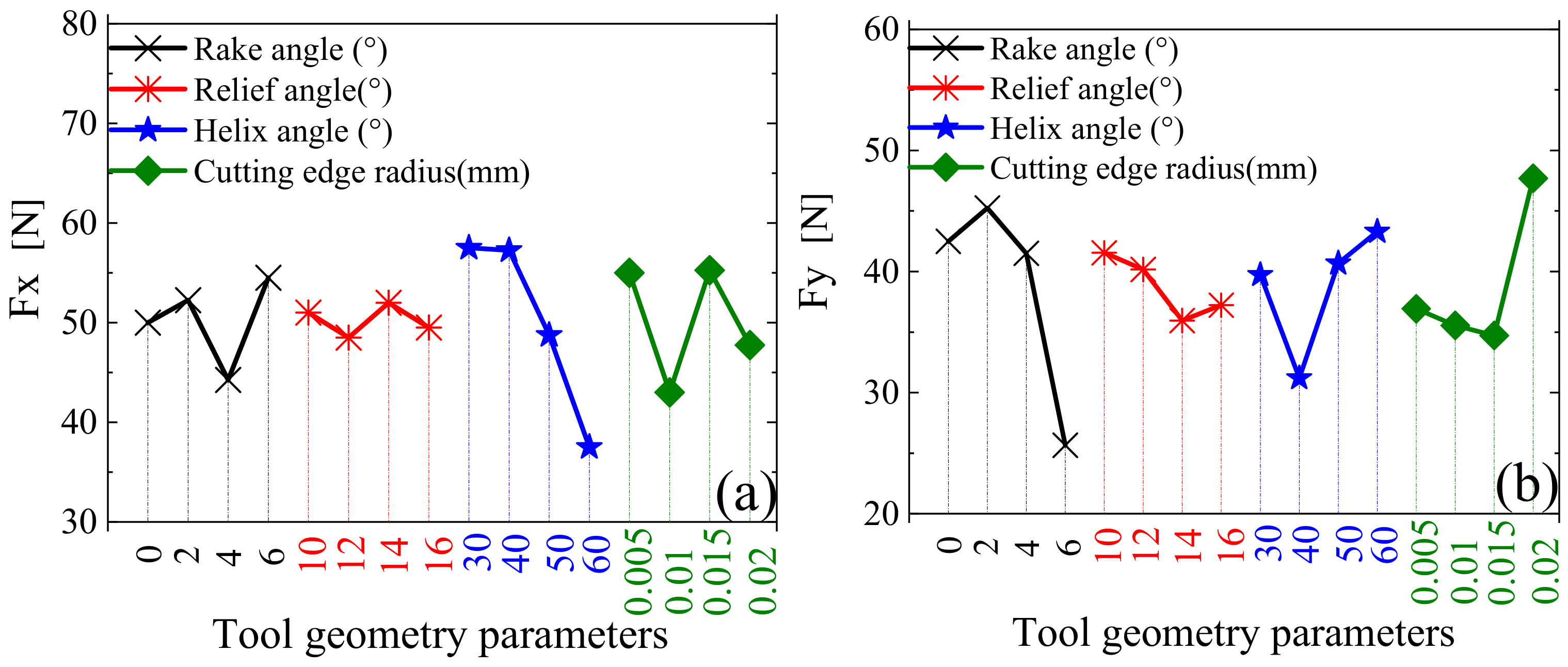
Using an orthogonal design of a model simulation for tool parameters, which is presented in Table 4 along with other relevant parameters listed in Table 5, the influence of tool geometry parameters on cutting force was calculated. The results are shown in Figure 12, where Fx represents the feed direction and Fy represents the width of cut direction.
In Figure 12, it can be seen that, within the range of the selected parameters: Fx fluctuates and Fy decreases with an increase in the rake angle; both Fx and Fy exhibit a small decrease with an increase in the relief angle; Fx decreases and Fz noticeably increases with increasing helix angle; and, with an increase in the cutting edge radius, Fx is stable and Fy increases.
The sensitivity of tool geometry parameters to the cutting force is shown in Figure 13. As can be seen, for Fx, helix angle had the greatest influence, cutting edge radius and rake angle had the second largest effects, and relief angle had the least influence. For Fy, the rake angle had the greatest influence, followed closely by the cutting edge radius and helix angle, while the relief angle had the least influence. Thus, it is obvious that the tool geometry parameters had different influences on the cutting forces.
4.2. Influence of Ultrasonic Parameters on Cutting Force
In LTUM, the influence of ultrasonic parameters (longitudinal amplitude, torsional amplitude, frequency and longitudinal-torsional phase difference) on the processing results cannot be neglected. However, in the experiment, it was very difficult to obtain a series of ultrasonic parameters by changing the acoustic system. Accordingly, our theoretical model realized the analysis of the influence of ultrasonic parameters on the processing results both economically and efficiently.
According to the orthogonal design, four factors and four levels were adopted, as shown in Table 6. The simulation results are shown in Figure 14, while the cutting and tool geometry parameters are shown in Table 7.
In Figure 14, it can be seen that, within the range of the selected parameters: Fx decreases and Fy fluctuates over a small range with an increase in longitudinal amplitude; Fx fluctuates over a small range and Fy decreases with increasing torsional amplitude; Fx and Fy increase with increasing ultrasonic frequency; and, with increasing longitudinal-torsional phase difference, Fx and Fy first decrease and then increase, reaching a minimum value at 30°.
The sensitivity of ultrasonic parameters to cutting force is shown in Figure 15. As can be seen, for both Fx and Fy, longitudinal-torsional phase difference had the greatest influence, followed closely by ultrasonic frequency and longitudinal amplitude, while torsional amplitude had the least influence.
4.3. Influence of Milling Parameters on Cutting Force
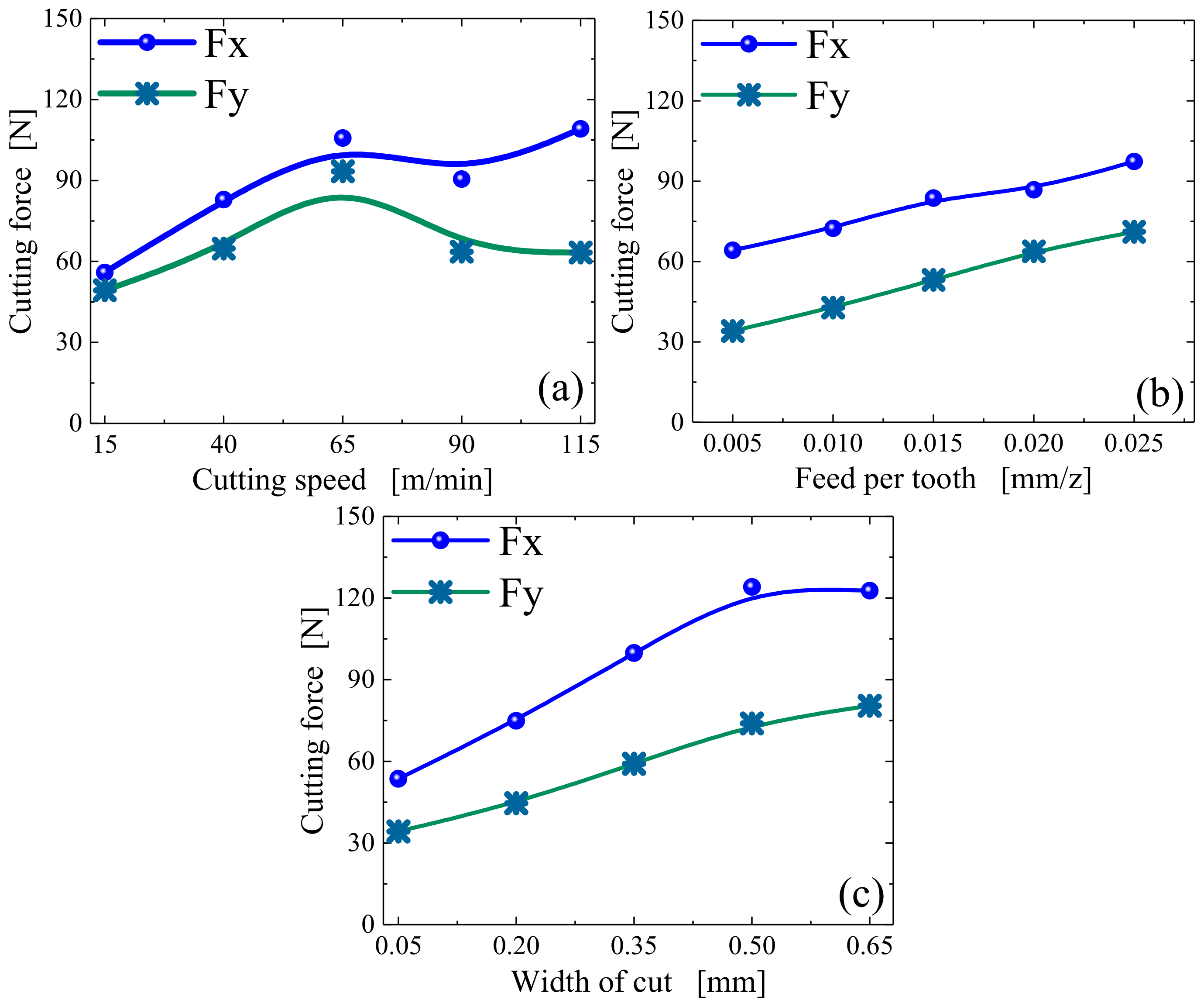
In addition to tool geometry and ultrasonic parameters, milling parameters also have a great influence on cutting force. According to the orthogonal design, four factors and four levels were adopted, as shown in Table 8, with the simulation results shown in Figure 16.
As can be seen in Figure 16a, with an increase in the cutting speed, both Fx and Fy gradually increase and then exhibit a small decrease in the final stage. The main reasons for this phenomenon are as follows: Firstly, with increasing cutting speed, the material removal volume of per unit time increases, resulting in a gradual increase in cutting force. Secondly, the critical cutting speed has a greater influence on the separation characteristics in LTUM; thus, with an increase in cutting speed, the phenomenon of tool–chip separation is weakened, causing the cutting force to increase gradually. In addition, an increase in cutting speed increases the material removal rate, causing a gradual increase in the cutting heat, thereby increasing of the workpiece temperature. This has an influence on the physical properties of the materials, such that the cutting force has a certain degree of decline when the cutting speed reaches a specific value.
From Figure 16b,c, with increasing of feed per tooth and width of cut, the cutting forces Fx and Fy increase in varying degrees, and the trend is similar. The main reason is that with increasing of feed per tooth and width of cut, the material removal per unit time increases as well, caused shear force increases, resulting in the gradual increase of cutting force.
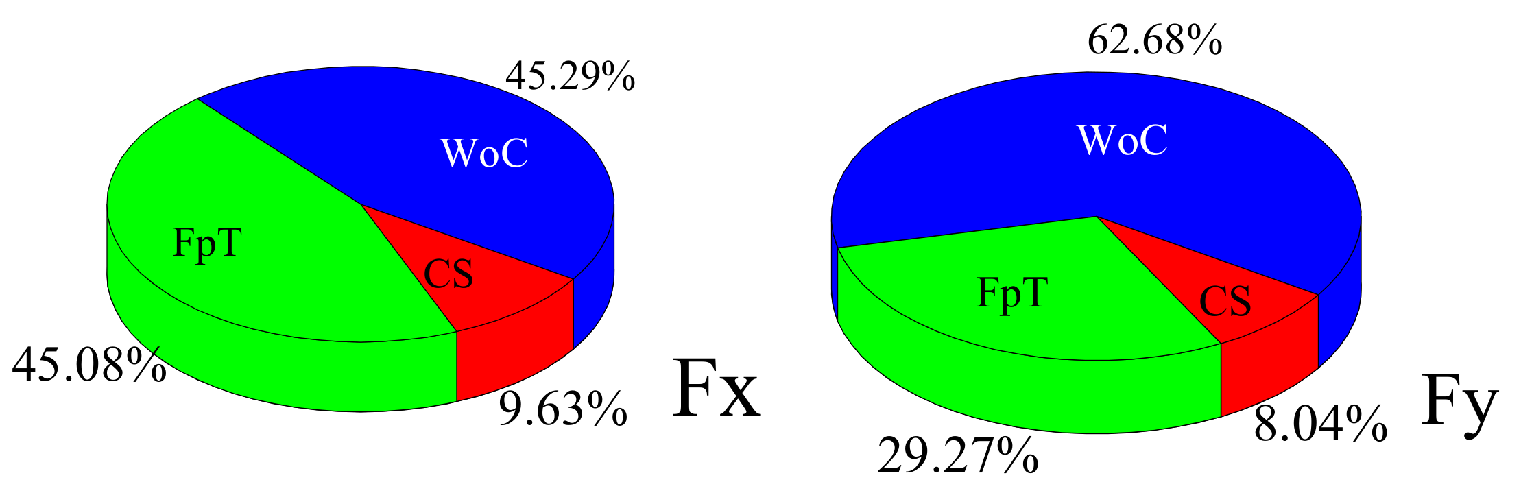
The sensitivity of ultrasonic parameters to cutting force is shown in Figure 17. As can be seen, the width of cut had the greatest influence on Fx and Fy, with a contribution rate of 45.29% and 62.68%, respectively. The feed per tooth followed closely, with a contribution rate of 45.08% and 29.27% for Fx and Fy, respectively. The cutting speed had the least influence for both cutting force directions. The main reason for this is that cutting force has a direct relationship with undeformed chip thickness, while both width of cut and feed per tooth have a great influence on undeformed chip thickness. Therefore, width of cut and feed per tooth have greater influences on the cutting force.
5. Conclusions
In this work, an LTUM machining method was proposed to meet the compressive stress and anti-fatigue manufacturing requirements of titanium alloy Ti-6Al-4V. In addition, models of cutting edge trajectory and undeformed chip thickness were presented. From these, a cutting force model of the LTUM method was established and verified through a series of experiments. Based on the established model, the influence of several parameters on cutting force were able to be analyzed. The major conclusions of this work are:
- (1)
- The undeformed chip thickness of the LTUM method was quite different from TM, and had a great influence on cutting force.
- (2)
- Based on the experimental verification, the established theoretical model of cutting force was in good agreement with the experimental results.
- (3)
- Based on the established cutting force model, the cutting force was lower in LTUM compared to TM. Specifically, Fx decreased by 24.8% and Fy decreased by 29.9%.
- (4)
- Based on the established cutting force model, the tool geometry parameters, ultrasonic parameters and milling parameters each influenced the cutting forces differently.
Author Contributions
Y.N. conceived and designed theory and experiments, and wrote the primary manuscript; F.J. check all the theory, experiments, and revised the manuscript; B.Z. contributed theory analysis and detail; G.G. contributed experiments analysis.
Funding
The paper is sponsored by National Natural Science Foundation of China (No. 51675164, No. U1604255, No. 51875179).
Conflicts of Interest
The authors declare no conflict of interest.
References
- Storchak, M.; Rupp, P.; Mohring, H.C.; Stehle, T. Determination of Johnson-Cook Constitutive Parameters for Cutting Simulations. Metals 2019, 9, 473. [Google Scholar] [CrossRef]
- Maly, M.; Holler, C.; Skalon, M.; Meier, B.; Koutny, D.; Pichler, R.; Sommitsch, C.; Palousek, D. Effect of Process Parameters and High-Temperature Preheating on Residual Stress and Relative Density of Ti6Al4V Processed by Selective Laser Melting. Materials 2019, 12, 930. [Google Scholar] [CrossRef] [PubMed]
- Slodki, B.; Zebala, W.; Struzikiewicz, G. Turning Titanium Alloy, Grade 5 ELI, with the Implementation of High Pressure Coolant. Materials 2019, 12, 768. [Google Scholar] [CrossRef] [PubMed]
- Polini, W.; Turchetta, S. Cutting Force, Tool Life and Surface Integrity in Milling of Titanium Alloy Ti-6Al-4V with Coated Carbide Tools. J. Eng. Manuf. 2016, 230, 694–700. [Google Scholar] [CrossRef]
- Shokrani, A.; Newman, S.T. A New Cutting Tool Design for Cryogenic Machining of Ti-6Al-4V Titanium Alloy. Materials 2019, 12, 477. [Google Scholar] [CrossRef] [PubMed]
- Madarkar, R.; Agarwal, S.; Attar, P.; Ghosh, S.; Rao, P.V. Application of Ultrasonic Vibration Assisted MQL in Grinding of Ti–6Al–4V. Mater. Manuf. Process. 2018, 33, 1445–1452. [Google Scholar] [CrossRef]
- Zhao, C.Y.; Wang, X.B.; Zhao, B.; Jiao, F. Microstructure of High-Performance Aluminum Alloy Surface Processed by the Single-Excitation Same-Frequency Longitudinal-Torsional Coupled Ultrasonic Vibration Milling. Materials 2018, 11, 1975. [Google Scholar] [CrossRef]
- Chowdhury, M.; Ullah, A.; Anwar, S. Drilling High Precision Holes in Ti6Al4V Using Rotary Ultrasonic Machining and Uncertainties Underlying Cutting Force, ToolWear, and Production Inaccuracies. Materials 2017, 10, 1069. [Google Scholar] [CrossRef]
- Chern, G.; Chang, Y. Using Two-Dimensional Vibration Cutting for Micro-Milling. Int. J. Mach. Tools Manuf. 2006, 46, 659–666. [Google Scholar] [CrossRef]
- Shen, X.H.; Zhang, J.H.; Li, H.; Wang, J.J.; Wang, X.C. Ultrasonic Vibration-Assisted Milling of Aluminum Alloy. Int. J. Adv. Manuf. Technol. 2012, 63, 41–49. [Google Scholar] [CrossRef]
- Zarchi, M.M.; Abootorabi, M.; Razfar, R. The Fundamental Geometry of Cutting Tools. Int. J. Adv. Manuf. Technol. 2013, 66, 83–89. [Google Scholar]
- Zhao, C.; Gong, H.; Fang, F.Z.; Li, Z.J. Experimental Study on the Cutting Force Difference Between Rotary Ultrasonic Machining and Conventional Diamond Grinding of K9 Glass. Mach. Sci. Technol. 2013, 17, 129–144. [Google Scholar] [CrossRef]
- Liang, Z.; Wang, X.; Wu, Y.; Zhao, W.; Peng, Y.; Xu, W. Development of a Two-Dimensional Ultrasonic Vibration Assisted Grinding Technique of Monocrystal Silicon. J. Mech. Eng. 2010, 46, 192–198. [Google Scholar] [CrossRef]
- Yanyan, Y.; Bo, Z.; Junli, L. Ultraprecision Surface Finishing of nano-ZrO2ceramics Using Two-Dimensional Ultrasonic Assisted Grinding. Int. J. Adv. Manuf. Technol. 2009, 43, 462–467. [Google Scholar] [CrossRef]
- Niu, Y.; Jiao, F.; Zhao, B.; Wang, D. Multiobjective Optimization of Processing Parameters in Longitudinal-Torsion Ultrasonic Assisted Milling of Ti-6Al-4V. Int. J. Adv. Manuf. Technol. 2017, 93, 4345–4356. [Google Scholar] [CrossRef]
- Xiang, D.; Wu, B.; Yao, Y.; Liu, Z.; Feng, H. Ultrasonic Longitudinal-Torsional Vibration-Assisted Cutting of Nomex® Honeycomb-Core Composites. Int. J. Adv. Manuf. Technol. 2019, 100, 1521–1530. [Google Scholar] [CrossRef]
- Liu, D.; Cong, W.L.; Pei, Z.J.; Tang, Y. A Cutting Force Model for Rotary Ultrasonic Machining of Brittle Materials. Int. J. Mach. Tools Manuf. 2012, 52, 77–84. [Google Scholar] [CrossRef]
- Zhang, C.; Zhang, J.; Feng, P. Mathematical Model for Cutting Force in Rotary Ultrasonic Face Milling of Brittle Materials. Int. J. Adv. Manuf. Technol. 2013, 69, 161–170. [Google Scholar] [CrossRef]
- Xiao, X.; Zheng, K.; Liao, W. Theoretical Model for Cutting Force in Rotary Ultrasonic Milling of Dental Zirconia Ceramics. Int. J. Adv. Manuf. Technol. 2014, 75, 1263–1277. [Google Scholar] [CrossRef]
- Yuan, S.; Fan, H.; Amin, M.; Zhang, C.; Guo, M. A Cutting Force Prediction Dynamic Model for Side Milling of Ceramic Matrix Composites C/SiC Based on Rotary Ultrasonic Machining. Int. J. Adv. Manuf. Technol. 2016, 86, 37–48. [Google Scholar] [CrossRef]
- Cong, W.L.; Pei, Z.J.; Sun, X.; Zhang, C.L. Rotary Ultrasonic Machining of Cfrp: A Mechanistic Predictive Model for Cutting Force. Ultrasonics 2014, 54, 663–675. [Google Scholar] [CrossRef] [PubMed]
- Wang, H.; Hu, Y.; Cong, W.; Hu, Z. A Mechanistic Model on Feeding-Directional Cutting Force in Surface Grinding of CFRP Composites Using Rotary Ultrasonic Machining with Horizontal Ultrasonic Vibration. Int. J. Mech. Sci. 2019, 155, 450–460. [Google Scholar] [CrossRef]
- Merchant, M.E. Mechanics of the Metal Cutting Process. I. Orthogonal Cutting and a Type 2 Chip. J. Appl. Phys. 1945, 16, 267–275. [Google Scholar] [CrossRef]
- Stabler, G.V. The Fundamental Geometry of Cutting Tools. Arch. Proc. Inst. Mech. Eng. 1951, 165, 14–26. [Google Scholar] [CrossRef]
- Amin, M.; Yuan, S.; Israr, A.; Zhen, L.; Qi, W. Development of Cutting Force Prediction Model for Vibration-Assisted Slot Milling of Carbon Fiber Reinforced Polymers. Int. J. Adv. Manuf. Technol. 2018, 94, 3863–3874. [Google Scholar] [CrossRef]
Figure 1.
Longitudinal-torsional ultrasonic vibration-assisted milling.
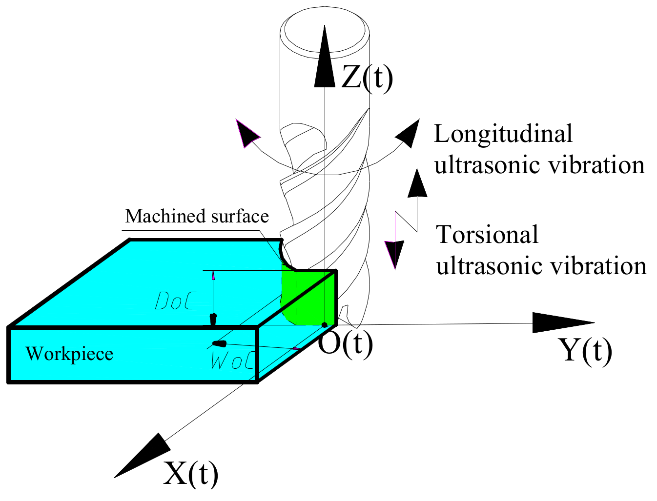
Figure 2.
Cutting edge trajectories of longitudinal-torsion ultrasonic-assisted milling (LTUM) and traditional milling (TM).
Figure 2.
Cutting edge trajectories of longitudinal-torsion ultrasonic-assisted milling (LTUM) and traditional milling (TM).

Figure 3.
Cutting edge trajectory characteristics in LTUM.
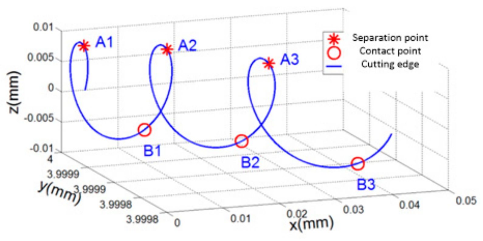
Figure 4.
Model of undeformed chip thickness.
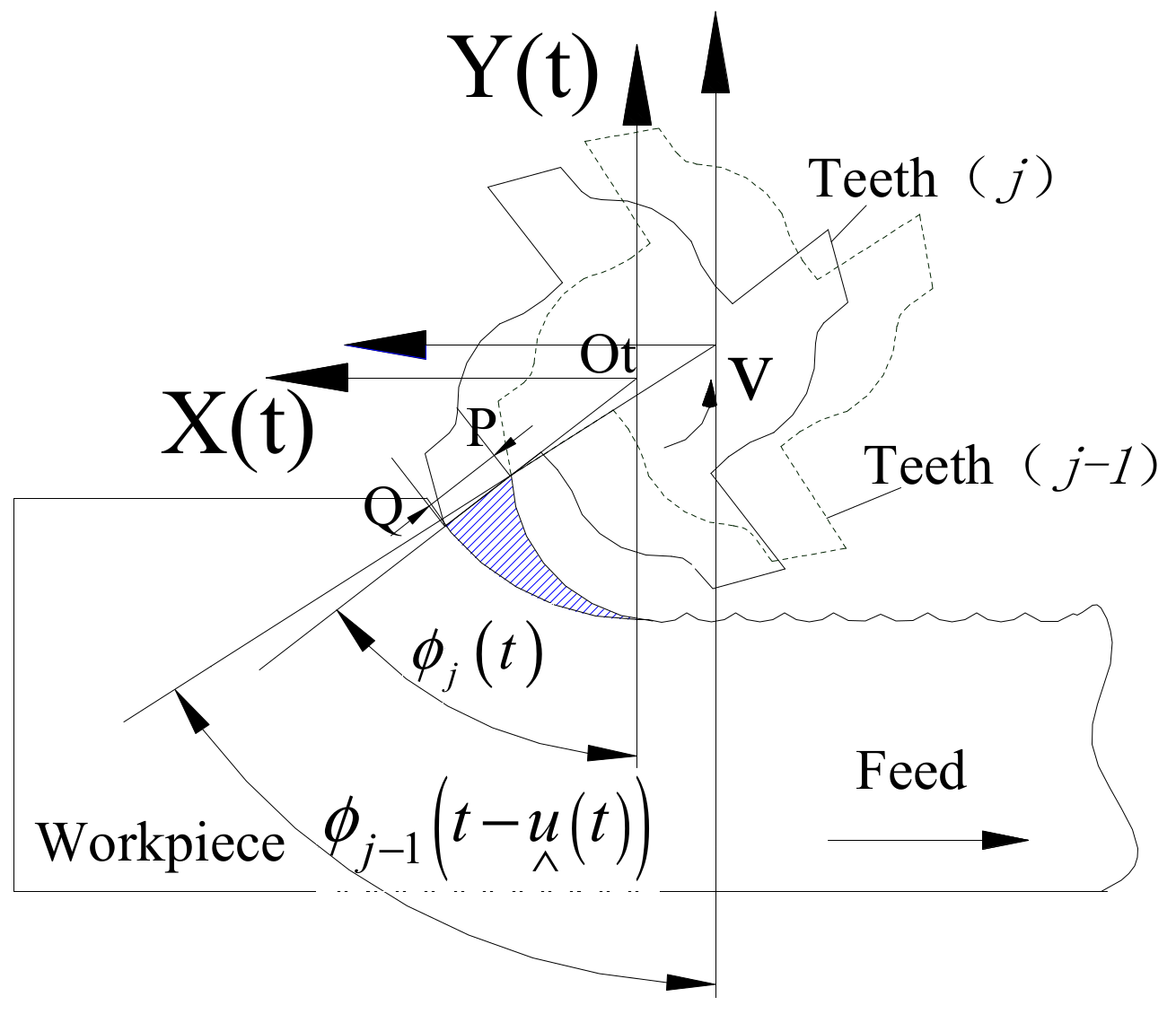
Figure 5.
Model of oblique cutting.

Figure 6.
Geometric relationship of cutting force model.
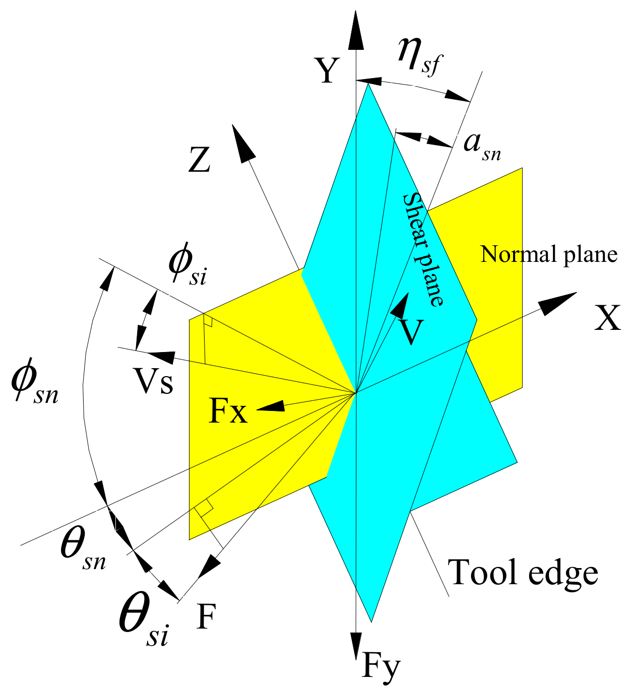
Figure 7.
Longitudinal-torsional ultrasonic vibration system.
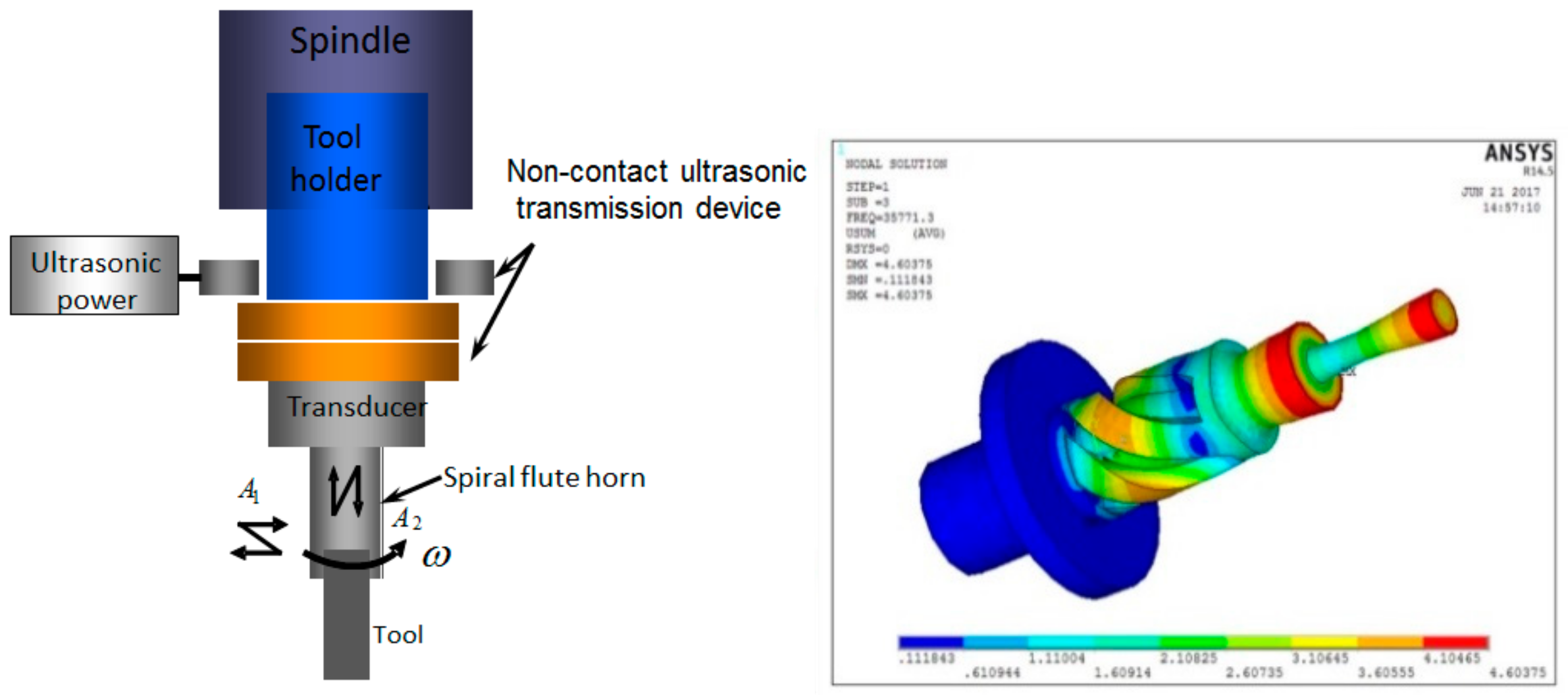
Figure 8.
Experimental devices.

Figure 9.
Predicted and experimental results of cutting force (cutting speed is 25 m/min, feed per tooth is 0.008 mm/z, width of cut is 0.15 mm, rake angle is 5°, relief angle is 12°, helix angle is 30°, cutting edge radius is 0.01 mm, longitudinal amplitude is 5 μm, torsional amplitude is 4 μm, and frequency is 35 kHz). (a) Model simulated result; (b) Experimental result.
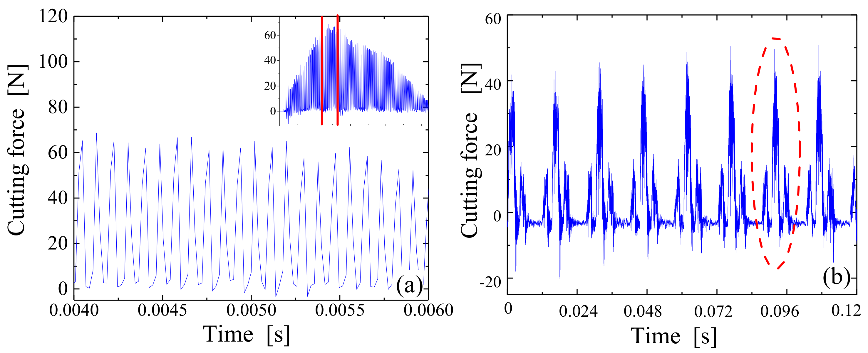
Figure 10.
Cutting force comparison of predicted and experimental results. (a) Under single tooth; (b) Under different processing parameters.
Figure 10.
Cutting force comparison of predicted and experimental results. (a) Under single tooth; (b) Under different processing parameters.
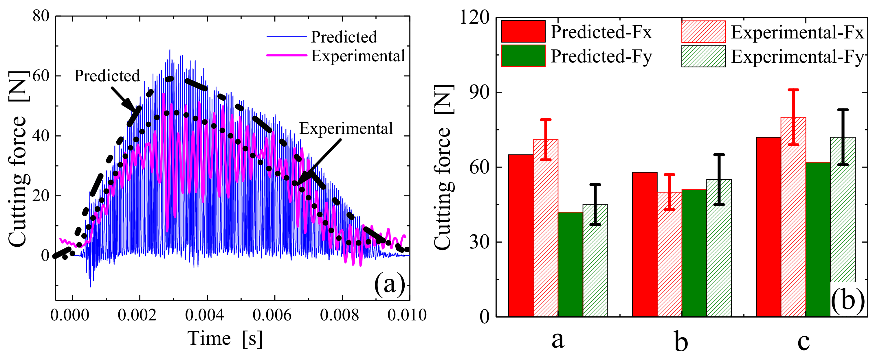
Figure 11.
Cutting force comparison of LTUM and TM.

Figure 12.
Response relationships between tool geometry parameters and cutting force. (a) Cutting force Fx; (b) Cutting force Fy.
Figure 12.
Response relationships between tool geometry parameters and cutting force. (a) Cutting force Fx; (b) Cutting force Fy.

Figure 13.
Relative sensitivity of tool geometry parameters to cutting force.

Figure 14.
Response relationships between ultrasonic parameters and cutting force. (a) Cutting force Fx; (b) Cutting force Fy.
Figure 14.
Response relationships between ultrasonic parameters and cutting force. (a) Cutting force Fx; (b) Cutting force Fy.
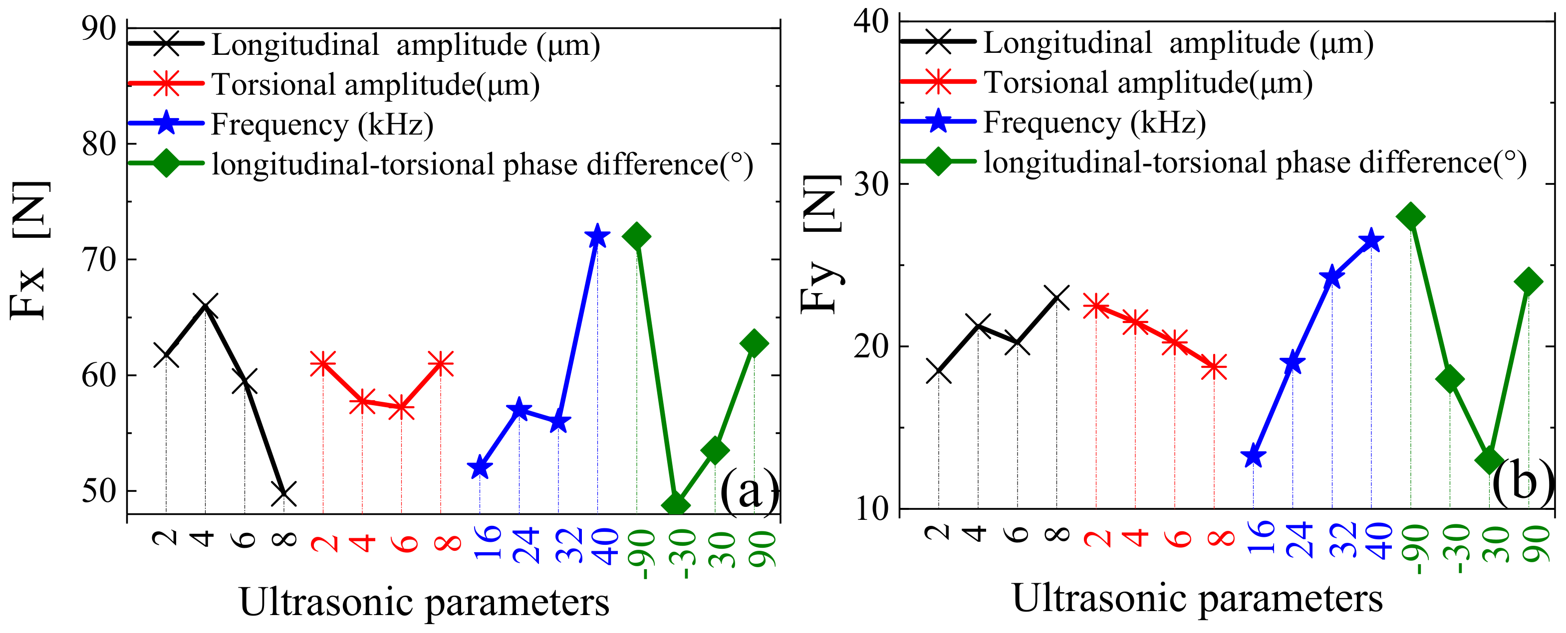
Figure 15.
Relative sensitivity of ultrasonic parameters to cutting force.
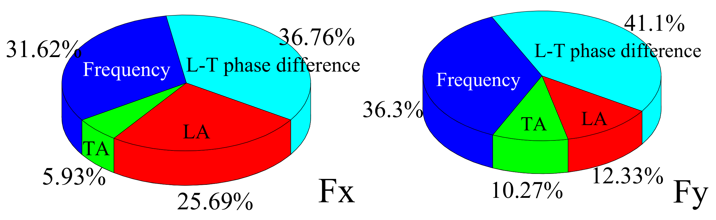
Figure 16.
Response relationships between cutting force and milling parameters. (a) Under different cutting speed; (b) Under different feed per tooth; (c) Under different width of cut.
Figure 16.
Response relationships between cutting force and milling parameters. (a) Under different cutting speed; (b) Under different feed per tooth; (c) Under different width of cut.

Figure 17.
Relative sensitivity of milling parameters to cutting force.

Table 1.
Milling parameters.
| Group | CS (m/min) | FpT (mm/z) | WoC (mm) | DoC (mm) |
|---|---|---|---|---|
| (a) | 25 | 0.008 | 0.15 | 2 |
| (b) and (c) | 40 | 0.005 | 0.1 | 2 |
Table 2.
Tool geometry parameters.
| Group | Rake Angle (°) | Relief Angle (°) | Helix Angle (°) | Cutting Edge Radius (mm) |
|---|---|---|---|---|
| (a), (b) and (c) | 5 | 12 | 30 | 0.01 |
Table 3.
Ultrasonic parameters.
| Group | LA (μm) | TA (μm) | Frequency (kHz) |
|---|---|---|---|
| (c) | 5 | 4 | 35 |
| (a) and (b) | 4 | 3.2 |
Table 4.
Simulated design for tool geometry parameters L16 (45).
| Lever | Rake Angle (°) | Relief Angle (°) | Helix Angle (°) | Cutting Edge Radius (mm) |
|---|---|---|---|---|
| No. 1 | 0 | 10 | 30 | 0.005 |
| No. 2 | 2 | 12 | 40 | 0.01 |
| No. 3 | 4 | 14 | 50 | 0.015 |
| No. 4 | 6 | 16 | 60 | 0.02 |
Table 5.
Cutting and ultrasonic parameters.
| CS (m/min) | FpT (mm/z) | WoC (mm) | DoC (mm) | LA (μm) | TA (μm) | Frequency (kHz) |
|---|---|---|---|---|---|---|
| 25 | 0.008 | 0.15 | 2 | 2 | 2 | 20 |
Table 6.
Design for ultrasonic parameters L16 (45).
| Lever | LA (μm) | T (μm) | Frequency (kHz) | Phase Difference (°) |
|---|---|---|---|---|
| No. 1 | 2 | 2 | 16 | −90 |
| No. 2 | 4 | 4 | 24 | −30 |
| No. 3 | 6 | 6 | 32 | 30 |
| No. 4 | 8 | 8 | 40 | 90 |
Table 7.
Cutting and tool geometry parameters.
| CS (m/min) | FpT (mm/z) | WoC (mm) | DoC (mm) | Rake Angle (°) | Relief Angle (°) | Helix Angle (°) | Cutting Edge Radius (μm) |
|---|---|---|---|---|---|---|---|
| 30 | 0.006 | 0.12 | 2 | 6 | 10 | 25 | 5 |
Table 8.
Design for milling parameters L16 (45).
| Lever | CS (m/min) | FpT (mm/tooth) | WoC (mm) |
|---|---|---|---|
| No. 1 | 20 | 0.006 | 0.1 |
| No. 2 | 40 | 0.012 | 0.2 |
| No. 3 | 60 | 0.018 | 0.3 |
| No. 4 | 80 | 0.024 | 0.4 |
© 2019 by the authors. Licensee MDPI, Basel, Switzerland. This article is an open access article distributed under the terms and conditions of the Creative Commons Attribution (CC BY) license (http://creativecommons.org/licenses/by/4.0/).
Share and Cite
MDPI and ACS Style
Niu, Y.; Jiao, F.; Zhao, B.; Gao, G. Investigation of Cutting Force in Longitudinal-Torsional Ultrasonic-Assisted Milling of Ti-6Al-4V. Materials 2019, 12, 1955. https://doi.org/10.3390/ma12121955
AMA Style
Niu Y, Jiao F, Zhao B, Gao G. Investigation of Cutting Force in Longitudinal-Torsional Ultrasonic-Assisted Milling of Ti-6Al-4V. Materials. 2019; 12(12):1955. https://doi.org/10.3390/ma12121955
Chicago/Turabian StyleNiu, Ying, Feng Jiao, Bo Zhao, and Guofu Gao. 2019. "Investigation of Cutting Force in Longitudinal-Torsional Ultrasonic-Assisted Milling of Ti-6Al-4V" Materials 12, no. 12: 1955. https://doi.org/10.3390/ma12121955
Note that from the first issue of 2016, this journal uses article numbers instead of page numbers. See further details here.