Investigation of Tool Wear and Chip Morphology in Dry Trochoidal Milling of Titanium Alloy Ti–6Al–4V


Key Laboratory of Contemporary Design and Integrated Manufacturing Technology of Ministry of Education, Northwestern Polytechnical University, Xi’an 710072, China
*
Author to whom correspondence should be addressed.
Materials 2019, 12(12), 1937; https://doi.org/10.3390/ma12121937
Submission received: 21 May 2019
/
Revised: 9 June 2019
/
Accepted: 14 June 2019
/
Published: 16 June 2019
(This article belongs to the Special Issue Machining—Recent Advances, Applications and Challenges)
Abstract
:Titanium alloys are widely used in the manufacture of aircraft and aeroengine components. However, tool wear is a serious concern in milling titanium alloys, which are known as hard-to-cut materials. Trochoidal milling is a promising technology for the high-efficiency machining of hard-to-cut materials. Aiming to realize green machining titanium alloy, this paper investigates the effects of undeformed chip thickness on tool wear and chip morphology in the dry trochoidal milling of titanium alloy Ti–6Al–4V. A tool wear model related to the radial depth of cut based on the volume of material removed (VMR) is established for trochoidal milling, and optimized cutting parameters in terms of cutting speed and axial depth of cut are selected to improve machining efficiency through reduced tool wear. The investigation enables the environmentally clean rough machining of Ti–6Al–4V.
1. Introduction
The application of titanium alloys has dramatically increased in many industries over the past half century, particularly in the aviation and aerospace industries, where about 80% of titanium production is used [1]. Such extensive application of titanium alloys is due to their excellent properties, such as high strength-to-weight ratio, good anticorrosion performance, and strong fracture resistance. Ti–6Al–4V accounts for the majority of the total consumption of all kinds of titanium alloys.
For most titanium alloy parts, especially aviation parts, traditional cutting methods such as turning, milling, drilling, and grinding are still the main means of processing and manufacturing [2,3]. However, titanium alloy is known as a kind of hard-to-cut material because of its several inherent properties, such as high chemical reactivity, low thermal conductivity, and low modulus of elasticity [4]. High chemical reactivity makes chip easily adhere to the tool-cutting edge. Low thermal conductivity increases the temperature at the tool cutting edge [5], which has an adverse effect on tool condition. Hence, tool wear is severe in the machining process of titanium alloy, and it will lead to serious machining vibration [6,7] or damage the machined surface quality [8]. In order to improve the tool life in the machining of titanium alloy, many research efforts have been made to assist in choosing suitable machining conditions. Effective cooling methods can significantly improve tool life by lowering the temperature of the tool cutting edge. Sun et al. [9] adopted the cryogenic compressed air cooling technique to cool the tool edge during the turning of Ti–6Al–4V. Pittalà [10] used CO2 cryogenic coolant in the end milling of Ti–6Al–4V. Bermingham et al. [11] made a comparison between cryogenic and high-pressure emulsion cooling technologies during the turning of Ti–6Al–4V, and found that high-pressure emulsion cooling achieved a slightly better tool life. Recently, minimum quantity lubrication (MQL) combined with cryogenic gas [12,13,14,15], such as carbon dioxide (CO2) and liquid nitrogen (LN2), has drawn great attention due to its excellent performance in improving tool life during machining hard-to-cut materials. Machining parameters such as the cutting speed, cutting depth, and feed rate have critical effects on tool life. Hou et al. [16] investigated the influence of cutting speed on tool wear in the end milling of Ti–6Al–4V, and the results showed the mean flank temperature and cutting force increased significantly as the cutting speed increased, which accelerated the tool wear. Jaffery et al. [17] indicated that the depth of cut had a significant effect on wear performance in machining Ti–6Al–4V alloy. To improve the machinability of Ti–6Al–4V, other approaches, such as laser-assisted machining [18], hybrid machining [19], and ultrasonic machining [20] were adopted by many researchers.
The improvement of tool life by the above-mentioned methods is at the expense of increased cost and energy consumption, even environmental pollution. To achieve the goals of green machining as well as the reduction of production cost, dry machining is considered as a promising and satisfactory solution in the future [21]. In the case of dry machining, the cleaning process of the workpiece can be spared, and the chips can be disposed of immediately without other treatment. Dry machining also has some positive effects, such as a reduction in thermal shock and no intrusion introduced by cooling equipment. However, the dry machining of titanium alloys is detrimental to the tool condition, because there will be more friction and adhesion between the tool and the workpiece without coolant, which will accelerate the tool wear [22]. Li et al. [23] investigated the effect of high cutting speed on tool wear in the dry milling of Ti–6Al–4V, and found that the increase in the cutting speed and feed rate accelerated the tool wear and drastically decreased the tool lifetime. Deng et al. [24] studied tool wear in the dry milling of Ti–6Al–4V, and found element diffusion from the Ti–6Al–4V titanium alloy to WC/Co carbide tools (and vice versa) at temperatures up to 400 °C. Li et al. [25] indicated that the main wear mechanisms of coated cemented carbide tools were the complicated interactions of several kinds of wear patterns—such as abrasive wear, coating delamination, adhesive wear, oxidation wear, and diffusion wear—at high cutting speed in the dry face milling of Ti–6Al–4V.
Trochoidal milling is a promising technology for the high-efficiency machining of hard-to-cut materials. This method is a combination of circular milling and slicing [26], which possesses a small engagement region between the tool and workpiece, and enables a relatively high feed rate and axial depth of cut to increase the machining efficiency. In trochoidal milling, the small engagement angle between the tool and workpiece generates low cutting forces, and a long period of non-engagement between the tool and workpiece ensures the effective cooling of the tool. These advantages enable a long tool life in trochoidal milling. Some research studies about trochoidal milling showed good practical results. Uhlmann et al. [27] indicated that trochoidal milling enabled lower energy consumption and process time in the machining of Ti–6Al–4V, compared with the conventional milling strategy. Wu et al. [28] investigated trochoidal milling in nickel-based superalloy, and the results showed that trochoidal milling significantly reduced tool flank wear. Patil et al. [29] adopted a trochoidal milling technique in the slot machining of Ti–6Al–4V, and found that it was better for surface finish and chip evacuation compared with the traditional slot milling method. In view of the merits of trochoidal milling, it is an effective method to reduce tool wear, as well as improve the machining efficiency and quality.
As mentioned above, dry trochoidal milling can be a potential high-efficiency green machining strategy. However, on reviewing the current research for the green milling of Titanium alloys, there appears to be limited reports on the machinability of the dry trochoidal milling of titanium alloy. To fill this research gap, this paper investigates the tool wear as well as the chip morphology in the dry trochoidal milling of titanium alloy Ti–6Al–4V based on a set of cutting experiments. Firstly, the effect that undeformed chip thickness had on tool wear and chip morphology was investigated in the dry milling of Ti–6Al–4V. The effects of radial cutting depth as well as cutting speed on tool wear were studied, and a tool wear model based on the volume of material removed (VMR) was then established based on the flank milling test. Finally, a set of optimized cutting parameters for the dry trochoidal milling of Ti–6Al–4V was selected and validated by cutting experiments.
2. Experimental Procedures
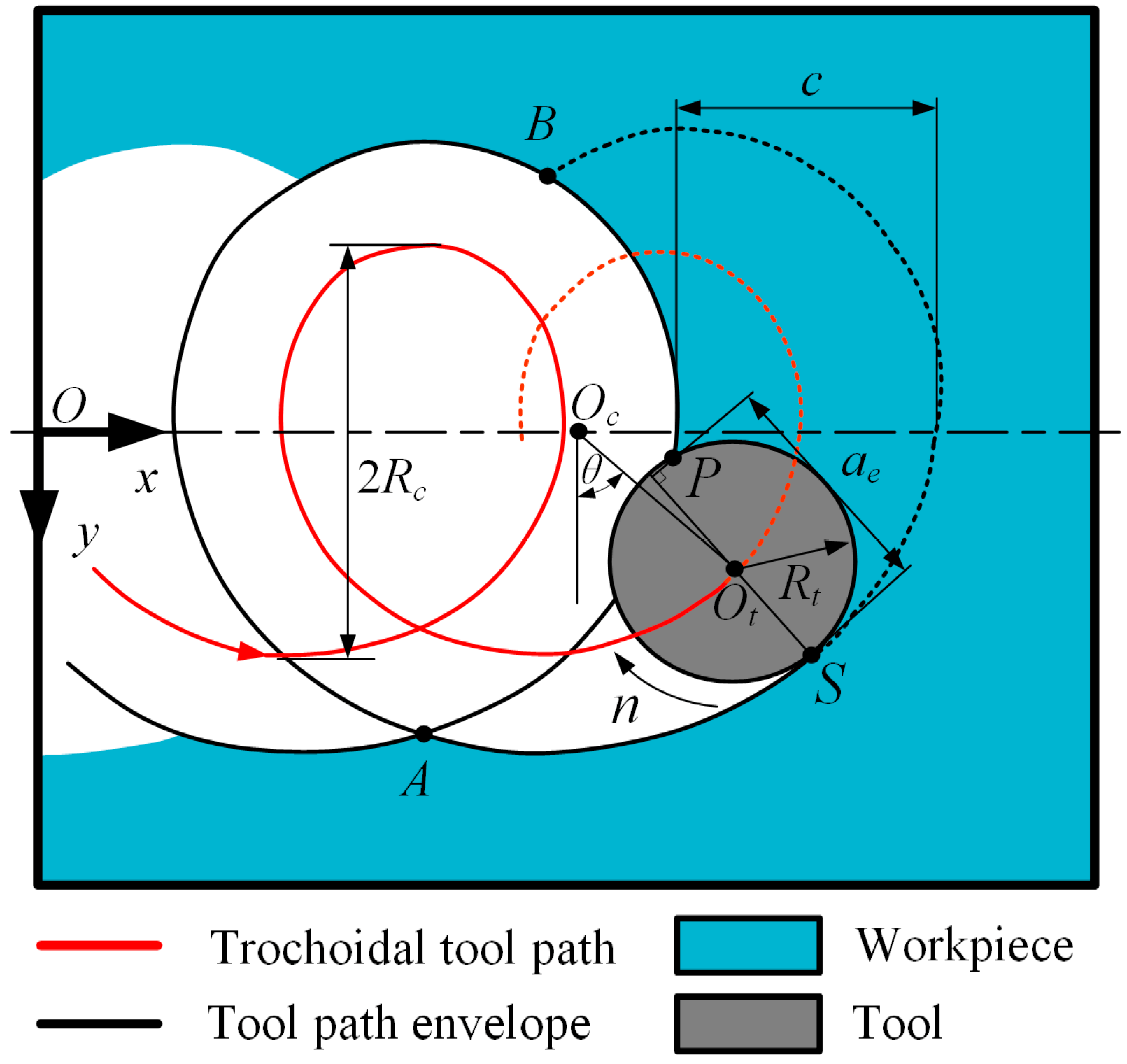
The trochoidal model enables continuity in both feed rate and acceleration due to its continuity in tangency and curvature [30], which is considered better concerning the kinematical behavior of the machine tool. The trochoidal model is shown in Figure 1. The tool center position Ot (xc,yc) parameterized by angle θ is expressed as follows:
where c is the trochoidal stepover, and Rc is the trochoidal radius. Point S is on the tool path envelope, and can be calculated using:
where Rt is the tool radius, and vector is normal to the trochoidal tool path. The tool contour (xt,yt) is determined by following expression:
Point P is the intersection point of the tool contour and tool path envelope, and can be solved by Equations (2) and (3). After calculating P, the instantaneous radial depth of cut can be obtained using:
Point A and point B are the tool entry and exit points in one trochoidal cycle. Between A and B, the instantaneous radial depth of cut increases continuously until reaching its maximal value when point P reaches the cusp [31], and then decreases to zero. The trochoidal model generates a non-symmetric tool path that is smooth toward its cusp, which is not located on x axis.
To improve machining efficiency, trochoidal milling usually adopts a large axial depth of cut and a small radial depth of cut. In combination with suitable cutting parameters and machining equipment, an axial depth of cut up to two times the tool diameter can be reached [27]. Compared with the axial depth of cut, the radial depth of cut related to chip thickness has a greater effect on the tool wear, since it affects the maximum undeformed chip thickness, which determines the maximum cutting force applied on the tool cutting edge. Additionally, cutting speed also has a great effect on tool life in milling titanium alloy [16]. Therefore, before performing the dry trochoidal milling test, the effects of radial cutting depth and cutting speed on the dry milling of Ti–6Al–4V are investigated by flank milling tests first.
2.1. Experimental Setup
The workpieces used in this study were annealed Ti–6Al–4V blocks with a size of 230 mm × 230 mm × 27 mm. The nominal chemical components and physical properties of the titanium alloys are listed in Table 1. The specifications of the used cutting tools are presented in Table 2. All the milling tests were conducted on an YHV850 three-axis machine tool (Yonghua Machinery Co., Ltd., Yanzhou, China) shown in Figure 2. Down milling was adopted in all the tests.
2.2. Experimental Design
The experimental design is focused on two main cutting parameters: the cutting speed and the radial depth of cut. The axial depth of cut is fixed at 2 mm, and the feed rate is fixed at 0.1 mm per tooth. Three levels of cutting speeds are selected, i.e., Vc = 60 m/min, 130 m/min, and 200 m/min. For each cutting speed, there are three levels of radial depths of cut, i.e., ae = 0.2 mm, 0.4 mm, and 0.6 mm. Detailed cutting parameters for all nine groups of tests are listed in Table 3.
For each test, the tool rejection or failure is judged according to the following criteria:
- (1)
- Average flank wear VB = 0.2 mm;
- (2)
- Maximum flank wear VB_max = 0.3 mm;
- (3)
- Excessive chipping/flaking or catastrophic failure.
The test will be stopped when any of the above criteria is reached. For the third criterion, the test result is invalid, and the test will be repeated until meeting one of the first two criteria. Then, the VMR will be calculated according to the cutting length.
3. Results and Analysis
3.1. Tool Wear Model Related with Radial Depth of Cut
Tool life results in terms of VMR are shown in Table 4, where the third column “effective cutting time” denotes the total time when the tool is engaged with the workpiece, and “MRR” represents the material removal rate. Suppose that the relationship between the radial depth of cut and VMR possesses a quadratic form as follows:
where A2, A1, and A0 are unknown coefficients.
According to the results in Table 4, the relationships between radial depth of cut and VMR for three levels of cutting speeds can be obtained by quadratic fitting (see Figure 3):
where VMR1, VMR2, and VMR3 correspond to cutting speeds of 60 m/min, 130 m/min, and 200 m/min, respectively. In Figure 3, it is observed that VMR decreases with the increase of cutting speed in the cutting speed range of 60 to 200 m/min. For each cutting speed, there is a radial depth of cut corresponding to the lowest VMR, which should be avoided in practical milling. More specifically, VMR at 0.4-mm radial depth of cut is lower than that at 0.2 mm and 0.6 mm radial depths of cut. This could be explained by the cutting force load increasing with the increase of radial depth of cut, thus accelerating the tool wear. However, when the radial depth of cut increased to 0.6 mm, a thicker chip carried away more cutting heat, which kept the tool in a better cutting condition despite a larger force load.
3.2. Tool Wear and Chip Morphology
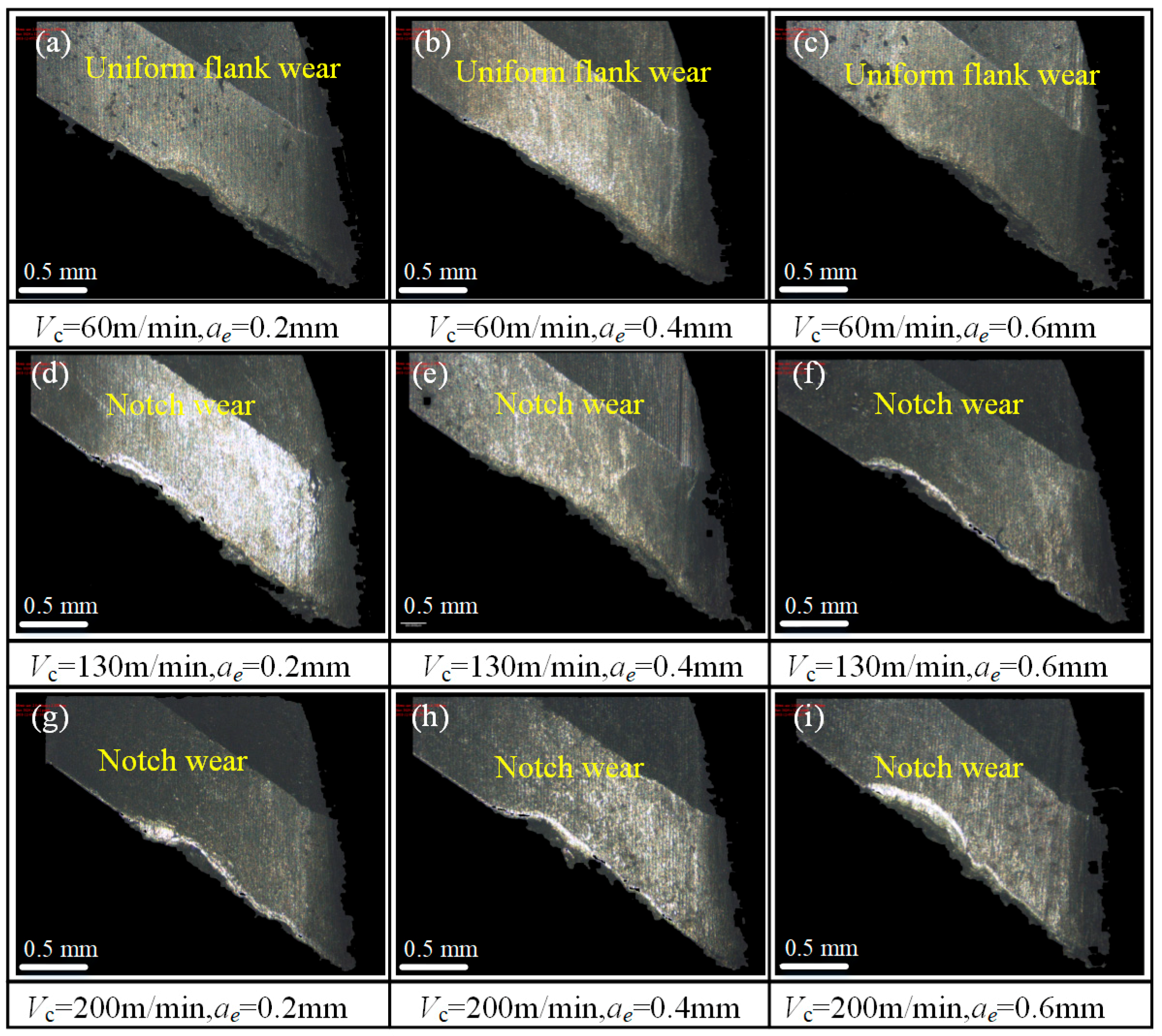
Tool edges of worn tools were scanned using Alicona Infinitefocus G4 (Graz, Austria) with a magnification of 50×, as shown in Figure 4. For three groups of tests at 60 m/min cutting speed (test no. 1, 2, and 3), the tool wear pattern is uniform flank wear. As the cutting speed increases to 130 m/min and 200 m/min, the tool wear pattern changes to notch wear, and the maximum wear position locates on the upper part of the tool edge. At the same radial depth of cut, the maximum flank wear increases as the cutting speed increases. At the same cutting speed, the higher the radial depth, the more serious the tool wear. For all the tests, tool wear on the tool tip is slight. As reported in [9], in milling titanium alloy, the cutting temperature increases dramatically with the increase in the cutting speed, and the tool wear progresses rapidly due to the high temperature and strong adhesion between the tool and workpiece material.
Chips during tests were collected and analyzed. The macro images of chips in test no. 1 are shown in Figure 5, where chip morphologies at different VMRs are presented. At the initial stage of tool life, the chips are uniform, regular, curled, and separated in shape due to intermittent milling and good tool condition [32] (see Figure 5a). Each chip can be divided into two sections: the corner section and the major section (see Figure 6a). The corner section was formed by the tool nose edge, and the major section was formed by the side cutting edge [33]. The back surface of the chip came into contact with the rake face of the tool under high contact pressure, and the friction is smooth and shiny, while the free surface of the chip is rough (see Figure 6a). When the VMR reaches 9200 mm3, chip separation has failed, which results in several chips sticking to each other (see Figure 5b). With the VMR increased to 27,000 mm3, chips with tight spiral shapes appear (see Figure 5c). As the VMR increases, the spiral radius increases (see Figure 5c,e). When the VMR is 46,000 mm3, the chip is twisted and irregular in shape. Besides, obvious scratches related to tool wear are observed on the back surface of the chip (see Figure 6b). At the end stage of tool life, serious distortion and scratches occur on the chip (see Figure 6c). It can be inferred that the worse the tool wear, the more severe the chip distortion.
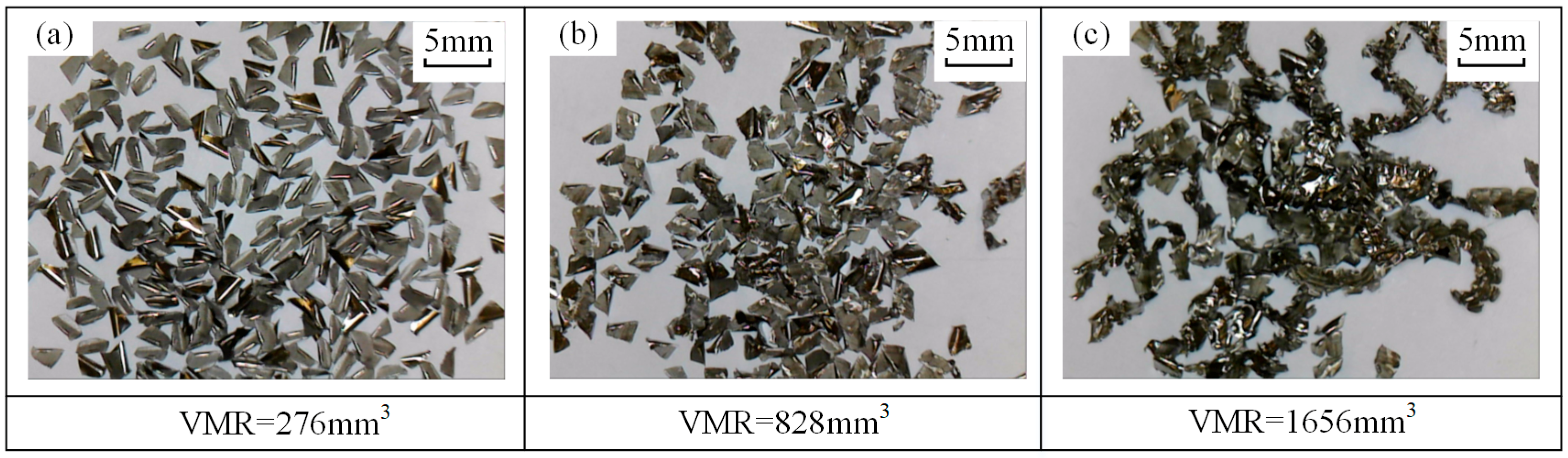
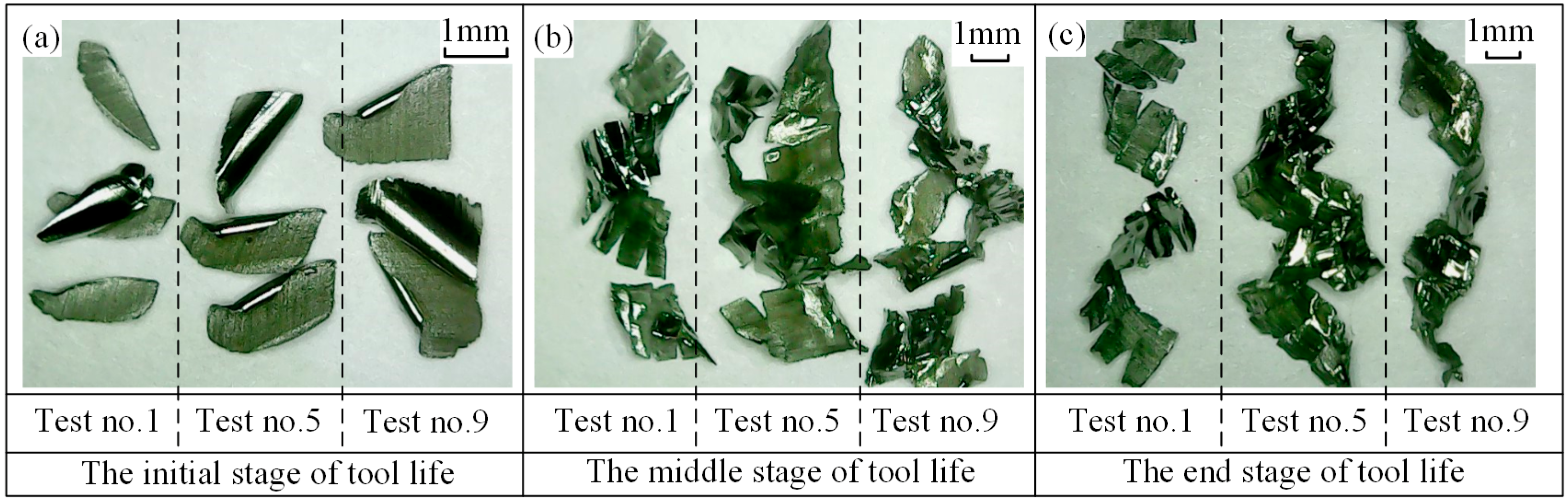
Chip morphologies in tests no. 5 and no. 9 are shown in Figure 7 and Figure 8, respectively. Comparisons of chip morphology between test no. 1, no. 5, and no. 9 are shown in Figure 9. The evolutions of chip morphology are similar for each test. At the initial stage of tool life, the chips are separated and regular in shape (see Figure 7a, Figure 8a and Figure 9a). At the middle stage, the chips begin to stick together (see Figure 7b, Figure 8b and Figure 9b). At the end stage, continuous chips with long spiral shapes appear (see Figure 7c, Figure 8c and Figure 9c), while the chips in test no. 1 are broken into pieces. Such a difference of chip morphologies between test no. 1 and test no. 5 or no. 9 is caused by the chip thickness. To be more specific, the radial depth of cut in test no. 1 is smaller than those in test no. 5 and no. 9, which causes the chip in test no. 1 to be thinner and easier to break. Chip morphologies in other tests were also observed, and it was found that the evolutions of chip morphology at the same radial depth were similar. The change of chip morphology is mainly caused by the tool wear and the formation of a built-up edge [34].
The results show that the cutting speed and the radial depth of cut have great influence on the VMR. To achieve a maximum VMR, the suggested cutting parameters are Vc = 60 m/min and ae = 0.6 mm when ap = 2 mm and fz = 0.1 mm/tooth in drying milling Ti–6Al–4V.
3.3. Trochoidal Milling Test
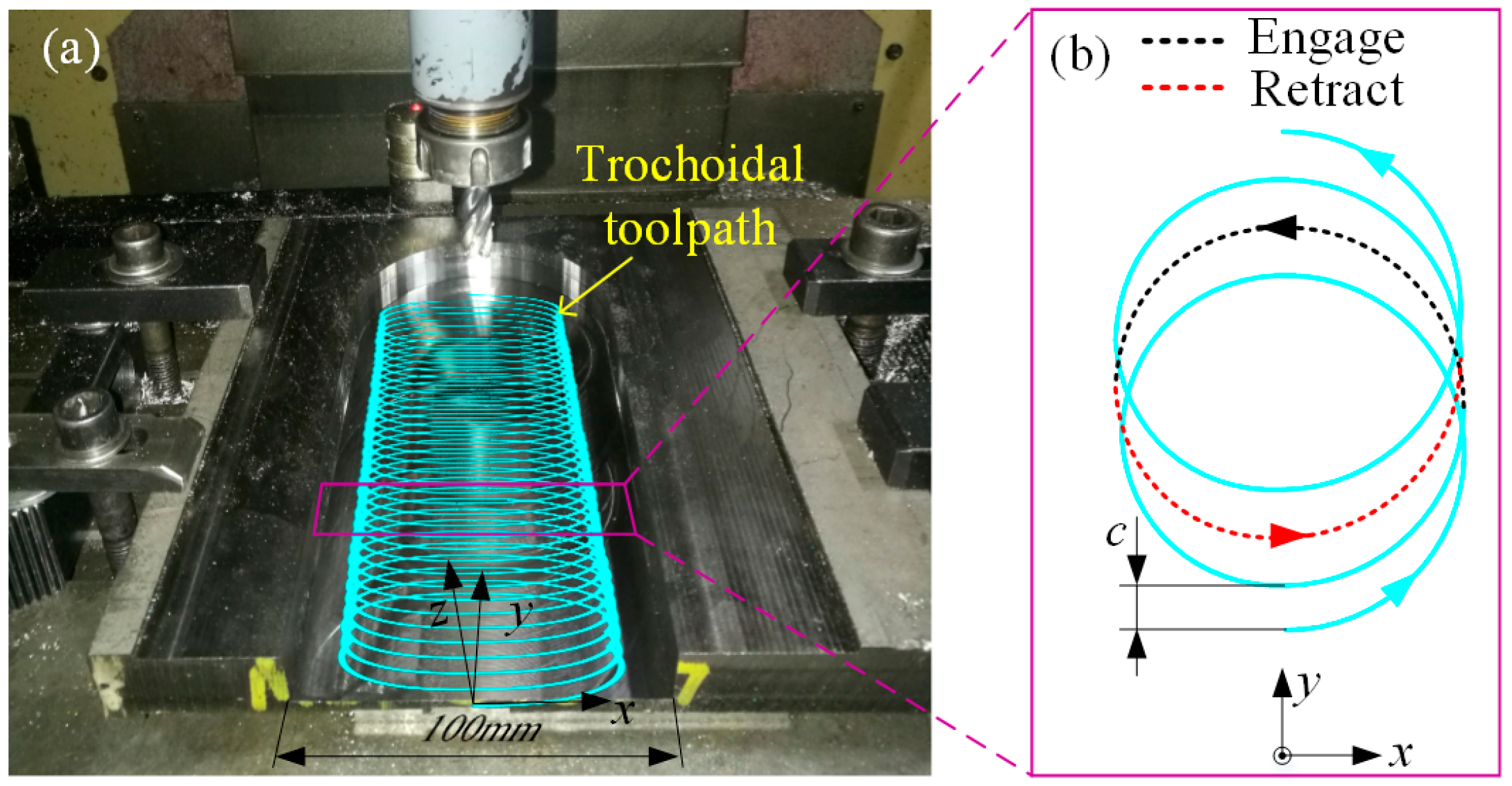
The test setup for trochoidal milling is shown in Figure 10a. The tool has the same specifications as those used in the above tests. Figure 10b shows the trochoidal toolpath, where c denotes the trochoidal stepover. One trochoid cycle is composed of a toolpath of retraction denoted by the red dot line and a toolpath of engagement denoted by the black dot line (see Figure 10b). According to the results of the flank milling tests, a combination of a 60 m/min cutting speed and 0.6-mm radial depth of cut achieved a maximum VMR. Thus, a set of cutting parameters—i.e., Vc = 60 m/min, fz = 0.1 mm/tooth, and c = 0.6 mm—was adopted in the trochoidal milling test, where the stepover corresponded to the radial depth of cut. Unlike the above tests, the axial depth of cut was set to 10 mm in this test to achieve a high material removal rate.
This test achieved a material removal rate of 1165.9 mm3/min and a total volume of 206,940 mm3 of material removed. The total cutting time, including the tool engaged and retracted time, was 177.5 min. The general view of the tool after the test is shown in Figure 11a, where lots of chip debris adhered to the rake face of the tool are observed, and the shapes of chips are diverse along the cutting edge. In addition, the TiAlN coating (dark color) on the engaged part of the tool had been worn away and the substrate material (bright color) of the tool was exposed. Figure 11b,c show enlarged views of the middle and tip position of the engaged cutting edge, respectively. In the figures, the materials removed from the workpiece were adhered to the flank face by cold welding. Moreover, small chippings, which perform as chip breakers, can be observed on the cutting edge [35].
The chips at different stages of tool life were collected in the trochoidal milling tests. Chip morphology images are shown in Figure 12. It is observed that each chip had an intact curled needle shape with serrated boundaries at an early stage of 10 min (see Figure 12a). At 80 min, distorted and obvious scratches could be seen on the back surface of the chip (see Figure 12b). At 177.5 min, several chips were twisted into a lump, and intact chips had broken into small pieces (see Figure 12c). It can be concluded that chip morphology is closely related to the tool wear condition and provides an important indication for tool condition monitoring.
4. Conclusions
This paper investigated the tool wear and chip morphology in the dry milling of titanium alloy Ti–6Al–4V for the aim of green machining titanium alloy. The effect of the radial depth of cut on tool wear was studied considering cutting speed, and a corresponding tool wear model related with radial cutting depth was established. According to the test results, cutting parameters in terms of radial depth of cut were optimized to improve the machining efficiency and reduce the tool wear. Then, the optimized cutting parameters were adopted by following the trochoidal milling test. Meanwhile, chips over the tool life cycle were collected and observed. Based on the results and analysis, the following conclusions can be drawn:
(1) For each cutting speed, Vc = 60, 130, and 200 m/min, there is a radial depth of cut corresponding to the lowest VMR, which should be avoided in practical milling. In this research, a 0.4-mm radial depth of cut should be avoided.
(2) In order to improve cutting efficiency in material removal, an appropriate radial depth of cut is necessary. In this paper, a 0.6-mm radial depth of cut combined with a 60 m/min cutting speed are suggested when ap = 2 mm and fz = 0.1 mm/tooth in drying milling titanium alloy Ti–6Al–4V.
(3) Trochoidal milling is a promising method for green machining titanium alloy. By using a 0.6-mm radial depth of cut and 60 m/min cutting speed, the material removal rate is 1165.93 mm3/min, and the tool life reaches 177.5 min in dry trochoidal milling.
(4) Chip morphology is closely associated with tool condition, and chip morphology can be adopted to monitor the tool condition.
Author Contributions
Conceptualization, M.L.; Investigation, D.L. and Y.Z.; Methodology, D.L. and M.L.; Supervision, M.L. and D.Z.; Validation, D.L. and Y.Z.; Writing—original draft, D.L. and Y.Z.; Writing—review & editing, M.L. and D.Z.
Funding
This work was supported by the National Science and Technology Major Project (Grant No. 2017ZX04013001).
Conflicts of Interest
The authors declare no conflict of interest.
References
- Cui, C.X.; Hu, B.M.; Zhao, L.C.; Liu, S.J. Titanium alloy production technology, market prospects and industry development. Mater. Des. 2011, 32, 1684–1691. [Google Scholar] [CrossRef]
- Yao, Q.; Luo, M.; Zhang, D.H.; Wu, B. Identification of cutting force coefficients in machining process considering cutter vibration. Mech. Syst. Sig. Process. 2018, 103, 39–59. [Google Scholar] [CrossRef]
- Han, C.; Luo, M.; Zhang, D.H.; Wu, B. Iterative Learning Method for Drilling Depth Optimization in Peck Deep-Hole Drilling. J. Manuf. Sci. Eng.-Trans. ASME. 2018, 140, 121009. [Google Scholar] [CrossRef]
- Komanduri, R.; Von Turkovich, B.F. New observations on the mechanism of chip formation when machining titanium alloys. Wear 1981, 69, 179–188. [Google Scholar] [CrossRef]
- Che-Haron, C.H.; Jawaid, A. The effect of machining on surface integrity of titanium alloy Ti–6% Al–4% V. J. Mater. Process. Technol. 2005, 166, 188–192. [Google Scholar] [CrossRef]
- Luo, M.; Yao, Q. Vibrations of Flat-End Cutter Entering Workpiece Process: Modeling, Simulations, and Experiments. Shock Vib. 2018, 2018, 8419013. [Google Scholar] [CrossRef]
- Yuan, H.; Wan, M.; Yang, Y. Design of a tunable mass damper for mitigating vibrations in milling of cylindrical parts. Chin. J. Aeronaut. 2019, 32, 748–758. [Google Scholar] [CrossRef]
- M’Saoubi, R.; Axinte, D.; Soo, S.L.; Nobel, C.; Attia, H.; Kappmeyer, G.; Engin, S.; Sim, W.-M. High performance cutting of advanced aerospace alloys and composite materials. CIRP Ann-Manuf. Technol. 2015, 64, 557–580. [Google Scholar] [CrossRef]
- Sun, S.; Brandt, M.; Dargusch, M.S. Machining Ti–6Al–4V alloy with cryogenic compressed air cooling. Int. J. Mach. Tools Manuf. 2010, 50, 933–942. [Google Scholar] [CrossRef]
- Pittalà, G.M. A study of the effect of CO2 cryogenic coolant in end milling of Ti-6Al-4V. Procedia CIRP. 2018, 77, 445–448. [Google Scholar] [CrossRef]
- Bermingham, M.J.; Palanisamy, S.; Kent, D.; Dargusch, M.S. A comparison of cryogenic and high pressure emulsion cooling technologies on tool life and chip morphology in Ti–6Al–4V cutting. J. Mater. Process. Technol. 2012, 212, 752–765. [Google Scholar] [CrossRef]
- Pereira, O.; Rodríguez, A.; Fernández-Abia, A.I.; Barreiro, J.; López de Lacalle, L.N. Cryogenic and minimum quantity lubrication for an eco-efficiency turning of AISI 304. J. Cleaner Prod. 2016, 139, 440–449. [Google Scholar] [CrossRef]
- Pereira, O.; Rodríguez, A.; Barreiro, J.; Fernández-Abia, A.I.; de Lacalle, L.N.L. Nozzle design for combined use of MQL and cryogenic gas in machining. Int. J. Precis. Eng. Manuf.-Green Technol. 2017, 4, 87–95. [Google Scholar] [CrossRef]
- Pereira, O.; Martín-Alfonso, J.E.; Rodríguez, A.; Calleja, A.; Fernández-Valdivielso, A.; López de Lacalle, L.N. Sustainability analysis of lubricant oils for minimum quantity lubrication based on their tribo-rheological performance. J. Cleaner Prod. 2017, 164, 1419–1429. [Google Scholar] [CrossRef]
- Pereira, O.; Rodríguez, A.; Ayesta, I.; García, J.B.; Fernández-Abia, A.I.; De Lacalle, L.N.L. A cryo lubri-coolant approach for finish milling of aeronautical hard-to-cut materials. Int. J. Mechatron. Manuf. Syst. 2016, 9, 370–384. [Google Scholar] [CrossRef]
- Hou, J.Z.; Zhou, W.; Duan, H.J.; Yang, G.; Xu, H.W.; Zhao, N. Influence of cutting speed on cutting force, flank temperature, and tool wear in end milling of Ti-6Al-4V alloy. Int. J. Adv. Manuf. Technol. 2014, 70, 1835–1845. [Google Scholar] [CrossRef]
- Jaffery, S.I.; Mativenga, P.T. Assessment of the machinability of Ti-6Al-4V alloy using the wear map approach. Int. J. Adv. Manuf. Technol. 2009, 40, 687–696. [Google Scholar] [CrossRef]
- Bermingham, M.J.; Palanisamy, S.; Dargusch, M.S. Understanding the tool wear mechanism during thermally assisted machining Ti-6Al-4V. Int. J. Mach. Tools Manuf. 2012, 62, 76–87. [Google Scholar] [CrossRef]
- Dandekar, C.R.; Shin, Y.C.; Barnes, J. Machinability improvement of titanium alloy (Ti–6Al–4V) via LAM and hybrid machining. Int. J. Mach. Tools Manuf. 2010, 50, 174–182. [Google Scholar] [CrossRef]
- Pujana, J.; Rivero, A.; Celaya, A.; López de Lacalle, L.N. Analysis of ultrasonic-assisted drilling of Ti6Al4V. Int. J. Mach. Tools Manuf. 2009, 49, 500–508. [Google Scholar] [CrossRef]
- Sreejith, P.S.; Ngoi, B.K.A. Dry machining: Machining of the future. J. Mater. Process. Technol. 2000, 101, 287–291. [Google Scholar] [CrossRef]
- Suárez, A.; Veiga, F.; Lópezde Lacalle, L.N.; Polvorosa, R.; Wretland, A. An investigation of cutting forces and tool wear in turning of Haynes 282. J. Manuf. Process. 2019, 37, 529–540. [Google Scholar] [CrossRef]
- Li, A.H.; Zhao, J.; Luo, H.B.; Pei, Z.Q.; Wang, Z.M. Progressive tool failure in high-speed dry milling of Ti-6Al-4V alloy with coated carbide tools. Int. J. Adv. Manuf. Technol. 2012, 58, 465–478. [Google Scholar] [CrossRef]
- Deng, J.X.; Li, Y.S.; Song, W.L. Diffusion wear in dry cutting of Ti–6Al–4V with WC/Co carbide tools. Wear 2008, 265, 1776–1783. [Google Scholar]
- Li, A.H.; Zhao, J.; Hou, G.M. Effect of cutting speed on chip formation and wear mechanisms of coated carbide tools when ultra-high-speed face milling titanium alloy Ti-6Al-4V. Adv. Mech. Eng. 2017, 9, 1–13. [Google Scholar] [CrossRef]
- Otkur, M.; Lazoglu, I. Trochoidal milling. Int. J. Mach. Tools Manuf. 2007, 47, 1324–1332. [Google Scholar] [CrossRef]
- Uhlmann, E.; Fürstmann, P.; Rosenau, B.; Gebhard, S.; Gerstenberger, R.; Müller, G. The Potential of Reducing the Energy Consumption for Machining TiAl6V4 by Using Innovative Metal Cutting Processes. In Proceedings of the Global Conference on Sustainable Manufacturing (GCSM), Berlin, Germany, 23–25 September 2013. [Google Scholar]
- Wu, B.H.; Zheng, C.Y.; Luo, M.; He, X.D. Investigation of trochoidal milling nickel-based superalloy. Mater. Sci. Forum. 2012, 723, 332–336. [Google Scholar] [CrossRef]
- Patil, P.; Polishetty, A.; Goldberg, M.; Littlefair, G.; Nomani, J. Slot machining of Ti6Al4V with trochoidal milling technique. Mach. Eng. 2014, 14, 42. [Google Scholar]
- Luo, M.; Han, C.; Hafeez, H.M. Four-axis trochoidal toolpath planning for rough milling of aero-engine blisks. Chin. J. Aeronaut. 2018. [Google Scholar] [CrossRef]
- Rauch, M.; Duc, E.; Hascoet, J.-Y. Improving trochoidal tool paths generation and implementation using process constraints modelling. Int. J. Mach. Tools Manuf. 2009, 49, 375–383. [Google Scholar] [CrossRef]
- Luo, M.; Luo, H.; Axinte, D.; Liu, D.S.; Mei, J.W.; Liao, Z.R. A wireless instrumented milling cutter system with embedded PVDF sensors. Mech. Syst. Sig. Process. 2018, 110, 556–568. [Google Scholar] [CrossRef] [Green Version]
- Li, A.H.; Zhao, J.; Zhou, Y.H.; Chen, X.X.; Wang, D. Experimental investigation on chip morphologies in high-speed dry milling of titanium alloy Ti-6Al-4V. Int. J. Adv. Manuf. Technol. 2012, 62, 933–942. [Google Scholar] [CrossRef]
- Álvarez, M.; Gómez, A.; Salguero, J.; Batista, M.; Huerta, M.M.; Marcos Bárcena, M. SOM-SEM-EDS Identification of Tool Wear Mechanisms in the Dry-Machining of Aerospace Titanium Alloys. Adv. Mater. Res. 2010, 107, 77–82. [Google Scholar] [CrossRef]
- Fernández-Vidal, S.R.; Mayuet, P.; Rivero, A.; Salguero, J.; del Sol, I.; Marcos, M. Analysis of the Effects of Tool Wear on Dry Helical Milling of Ti6Al4V Alloy. Procedia Eng. 2015, 132, 593–599. [Google Scholar] [CrossRef] [Green Version]
Figure 1.
Geometric model of trochoidal milling. Here, Ot is the tool center position; Oc the current revolution center of the tool center; θ is the revolution angle; c is the trochoidal stepover; Rc is the trochoidal radius; Rt is the tool radius; and ae is the current radial depth of cut.
Figure 1.
Geometric model of trochoidal milling. Here, Ot is the tool center position; Oc the current revolution center of the tool center; θ is the revolution angle; c is the trochoidal stepover; Rc is the trochoidal radius; Rt is the tool radius; and ae is the current radial depth of cut.

Figure 2.
Experimental setup.

Figure 3.
Relationship between radial depth of cut and VMR.

Figure 4.
Photos taken by Alicona Infinitefocus G4 for worn tools with cutting parameters (a) Vc = 60 m/min, ae = 0.2 mm, (b) Vc = 60 m/min, ae = 0.4 mm, (c) Vc = 60 m/min, ae = 0.6 mm, (d) Vc = 130 m/min, ae = 0.2 mm, (e) Vc = 130 m/min, ae = 0.4 mm, (f) Vc = 130 m/min, ae = 0.6 mm, (g) Vc = 200 m/min, ae = 0.2 mm, (h) Vc = 200 m/min, ae = 0.4 mm, and (i) Vc = 200 m/min, ae = 0.6 mm.

Figure 5.
Chip morphology (test no. 1: Vc = 60 m/min, ap = 2 mm, ae = 0.2 mm, fz = 0.1 mm/tooth) under VMR of (a) 92 mm3, (b) 9200 mm3, (c) 27,000 mm3, (d) 46,000 mm3, (e) 64,400 mm3, and (f) 77,280 mm3.
Figure 5.
Chip morphology (test no. 1: Vc = 60 m/min, ap = 2 mm, ae = 0.2 mm, fz = 0.1 mm/tooth) under VMR of (a) 92 mm3, (b) 9200 mm3, (c) 27,000 mm3, (d) 46,000 mm3, (e) 64,400 mm3, and (f) 77,280 mm3.

Figure 6.
Chip morphology in enlarged view (test no. 1: Vc = 60 m/min, ap = 2 mm, ae = 0.2 mm, fz = 0.1 mm/tooth) with VMR of (a) 92 mm3, (b) 46,000 mm3, and (c) 77,280 mm3.
Figure 6.
Chip morphology in enlarged view (test no. 1: Vc = 60 m/min, ap = 2 mm, ae = 0.2 mm, fz = 0.1 mm/tooth) with VMR of (a) 92 mm3, (b) 46,000 mm3, and (c) 77,280 mm3.

Figure 7.
Chips morphology (test no. 5: Vc = 130 m/min, ap = 2 mm, ae = 0.4 mm, fz = 0.1 mm/tooth) under VMR of (a) 184 mm3, (b) 1472 mm3, and (c) 2760 mm3.
Figure 7.
Chips morphology (test no. 5: Vc = 130 m/min, ap = 2 mm, ae = 0.4 mm, fz = 0.1 mm/tooth) under VMR of (a) 184 mm3, (b) 1472 mm3, and (c) 2760 mm3.

Figure 8.
Chips morphology (test no. 9: Vc = 200 m/min, ap = 2 mm, ae = 0.6 mm, fz = 0.1 mm/tooth) under VMR of (a) 276 mm3, (b) 828 mm3, and (c) 1656 mm3.
Figure 8.
Chips morphology (test no. 9: Vc = 200 m/min, ap = 2 mm, ae = 0.6 mm, fz = 0.1 mm/tooth) under VMR of (a) 276 mm3, (b) 828 mm3, and (c) 1656 mm3.

Figure 9.
Chip morphology at (a) initial stage (the VMR values for test no. 1, no. 5, and no. 9 are 92 mm3, 184 mm3, and 276 mm3), (b) middle stage (the VMR values at the middle stage for test no. 1, no. 5, and no. 9 are 46,000 mm3, 1472 mm3, and 828 mm3) and (c) end stage (the VMR values at the end stage for test no. 1, no. 5, and no. 9 are 77,280 mm3, 2760 mm3, and 1656 mm3) of tool life.

Figure 10.
(a) Dry trochoidal milling test; (b) Trochoidal toolpath.

Figure 11.
Tool condition after dry trochoidal milling test. (a) General view of the tool; (b) Top position; (c) Middle position; (d) Bottom positon.
Figure 11.
Tool condition after dry trochoidal milling test. (a) General view of the tool; (b) Top position; (c) Middle position; (d) Bottom positon.

Figure 12.
Chip morphology in trochoidal milling tests at cutting stage of (a) 10 min, (b) 80 min and (c) 177.5 min.
Figure 12.
Chip morphology in trochoidal milling tests at cutting stage of (a) 10 min, (b) 80 min and (c) 177.5 min.


Table 1.
Nominal chemical components and physical properties of the titanium alloys.
| Element | Al | V | Fe | O | C | N | H | Ti |
|---|---|---|---|---|---|---|---|---|
| wt.% | 5.5–6.8 | 3.5–4.5 | <0.5 | <0.2 | <0.1 | <0.05 | <0.015 | balance |
| Physical Properties | Density (kg/m3) | Elastic Modulus (GPa) | Yield Strength (MPa) | Thermal Conductivity (W/(m·K)) | Hardness (HRC) | Melting Point (°C) | ||
| value | 4430 | 113.8 | 880 | 6.7 | 36 | 1604–1660 | ||
Table 2.
Specifications of the helical milling cutter.
| Diameter (mm) | Number of Flutes | Helix Angle (°) | Corner Radius (mm) | Coating | Rake Angle (°) | Clearance Angle (°) | Second Clearance Angle (°) | Hardness (HRC) |
|---|---|---|---|---|---|---|---|---|
| 12 | 4 | 35 | 0.5 | TiAlN (3 μm) | 4 | 8 | 20 | 65 |
Table 3.
Cutting parameters used in the experiments (fz = 0.1 mm/tooth, ap = 2 mm).
| Test No. | Cutting Speed (m/min) | Radial Depth of Cut ae (mm) | Spindle Speed (rpm) | Feed Rate (mm/min) |
|---|---|---|---|---|
| 1 | 60 | 0.2 | 1592 | 637 |
| 2 | 0.4 | |||
| 3 | 0.6 | |||
| 4 | 130 | 0.2 | 3448 | 1379 |
| 5 | 0.4 | |||
| 6 | 0.6 | |||
| 7 | 200 | 0.2 | 5305 | 2122 |
| 8 | 0.4 | |||
| 9 | 0.6 |
Table 4.
Test results. VMR: volume of material removed.
| Test No. | VMR (mm3) | Effective Cutting Time (s) | MRR (mm3/min) |
|---|---|---|---|
| 1 | 77,280 | 18,198 | 254.8 |
| 2 | 30,360 | 3575 | 509.6 |
| 3 | 85,146 | 6683 | 764.4 |
| 4 | 45,080 | 4904 | 551.6 |
| 5 | 4692 | 255 | 1103.2 |
| 6 | 8786 | 319 | 1654.8 |
| 7 | 13,340 | 943 | 848.8 |
| 8 | 1472 | 52 | 1697.6 |
| 9 | 1518 | 36 | 2546.4 |
© 2019 by the authors. Licensee MDPI, Basel, Switzerland. This article is an open access article distributed under the terms and conditions of the Creative Commons Attribution (CC BY) license (http://creativecommons.org/licenses/by/4.0/).
Share and Cite
MDPI and ACS Style
Liu, D.; Zhang, Y.; Luo, M.; Zhang, D. Investigation of Tool Wear and Chip Morphology in Dry Trochoidal Milling of Titanium Alloy Ti–6Al–4V. Materials 2019, 12, 1937. https://doi.org/10.3390/ma12121937
AMA Style
Liu D, Zhang Y, Luo M, Zhang D. Investigation of Tool Wear and Chip Morphology in Dry Trochoidal Milling of Titanium Alloy Ti–6Al–4V. Materials. 2019; 12(12):1937. https://doi.org/10.3390/ma12121937
Chicago/Turabian StyleLiu, Dongsheng, Ying Zhang, Ming Luo, and Dinghua Zhang. 2019. "Investigation of Tool Wear and Chip Morphology in Dry Trochoidal Milling of Titanium Alloy Ti–6Al–4V" Materials 12, no. 12: 1937. https://doi.org/10.3390/ma12121937
Note that from the first issue of 2016, this journal uses article numbers instead of page numbers. See further details here.