1. Introduction
Single point incremental forming (SPIF) is a new technology for sheet metal. The suspended sheet metal is locally dynamically loaded by a specific tool head. The sheet is used to produce an overall cumulative deformation in a dieless and unconstrained state. Finally, the target part is obtained [
1]. Since the specific tool head is driven by a CNC (computerized numerical control) machine, this technology can form thin-walled components of various complex shapes. It is flexible, green, fast, and low-cost. However, the partial loading characteristics of the tool head and the suspended clamp characteristics of the sheet make the forming process susceptible to instability and the part susceptible to springback. This reduces forming accuracy, surface quality, and the forming limit of the part [
2].
For this reason, researchers in this field have made many attempts to study and improve the forming quality of parts. Shrivastava et al. [
3] analyzed the microstructural features in different stages of SPIF through electron back-scattered diffraction (EBSD) and X-ray diffraction (XRD) methods and identified the reasons for typical sheet metal failure. William L. Edwards et al. [
4] used experimental heating to process the springback area of the parts. The result showed that heating can effectively reduce the springback of the sheet. Allwood et al. [
5] reduced the springback of the part using a pre-manufactured hole in the blank area of the initial sheet metal. Although this method can improve the accuracy of the part, it reduces its rigidity. Parnika Shrivastava et al. [
6] preheated the sheet in advance for eliminating the defects in the crystal structure and homogenizing the grain size and distribution of the material. After preheating, the accuracy of the part was clearly improved, and the wall thickness distribution was more uniform. Yanle Li et al. [
7] measured the accuracy of the part by the axial error. According to the results, the optimum combination of the process parameters was obtained, which reduced the deformation energy and improved the forming accuracy at the same time. Lu et al. [
8] studied the influence of layer spacing on the accuracy of the part. It was found that the smaller the layer spacing, the higher the accuracy of the part. However, the forming time will be significantly increased with smaller layer spacing. A. Fiorentino et al. [
9] proposed a method to reduce the geometric error by compensation. This method is an iterative algorithm based on an artificial identification system. Experimental verification was carried out using different tool paths and materials in the non-axisymmetric part. Aqeel Sabree Bedan [
10] studied the influence of the ball tool, the hemispherical tool, and the fillet tool on the part accuracy of AL 1050 sheet metal by an NC (Numerical Control) vertical milling machine. It was found that the tool head diameter had the most significant effect on the geometric accuracy. Abolfazl Taherkhani et al. [
11] used the group method of data handling (GMDH), an artificial neural network to model the relationships between tool head diameter, layer spacing, sheet thickness, feed speed, axial accuracy, and surface quality. The model was validated by experiments. Italian scholar D. Mundo et al. [
12] applied high-frequency vibrations to sheet metal for SPIF. It improved the surface quality and reduced the distortion of parts. Iranian scholar M. Vahdati et al. [
13], using experiments, proved the effects of ultrasonic vibration (UV) on SPIF in reducing the axial force, springback, and surface roughness. Iranian scholar S. Amini et al. [
14] applied axial high frequency and low amplitude UV to the forming tool to form a 1050 aluminum straight groove. The results showed that UV can reduce the forming force and improve the formability. Japanese scholar Obikawa et al. [
15] carried out SPIF experiments of aluminum alloy, steel, and titanium sheets by UV. It was found that UV could significantly improve the geometric accuracy and forming limit of parts. Yanle Li et al. [
16] studied the deformation mechanism of sheet metal under UV-SPIF by finite element simulation. The influences of amplitude on the magnitude and distribution of plastic strain were obtained. In addition, some scholars have proposed such technologies as two-point incremental forming [
17], high-pressure water jet SPIF [
18], electric-assisted SPIF [
19], laser-assisted SPIF [
20], and electromagnetic incremental forming [
21,
22] in order to improve the quality of parts by changing the magnitude and action of forming force.
Scholars have done research in controlling forming accuracy and improving forming quality and have attained certain achievements. In order to further improve forming quality, in this paper, UV was applied to the tool head to improve the residual stress distribution, thereby reducing the springback of the part. The static pressure support (SPS) was also applied to the retaining sheet to change the suspension state, thereby improving the axial accuracy of the part. For this reason, the technology of simultaneously introducing ultrasonic vibration and static pressure support into the SPIF is proposed for the first time. Under the action of two auxiliary technologies, the magnitude and action of the forming force have changed. In order to study the SPS–UV single-point incremental forming (SPS-UV-SPIF) force, the working principle and motion rules of the technology are studied. The sheet micro-element of the formed contact area was taken as the analysis object. The spatial stress balance equation of the sheet micro-element was constructed. The stresses of the various directions were integrated, and the forming forces of the contact area were obtained and expressed analytically. An analytical model of the forming force of SPS-UV-SPIF was constructed, and the influence law of static pressure parameters and vibration parameters on the forming force was obtained. Finally, it was verified by experiments.
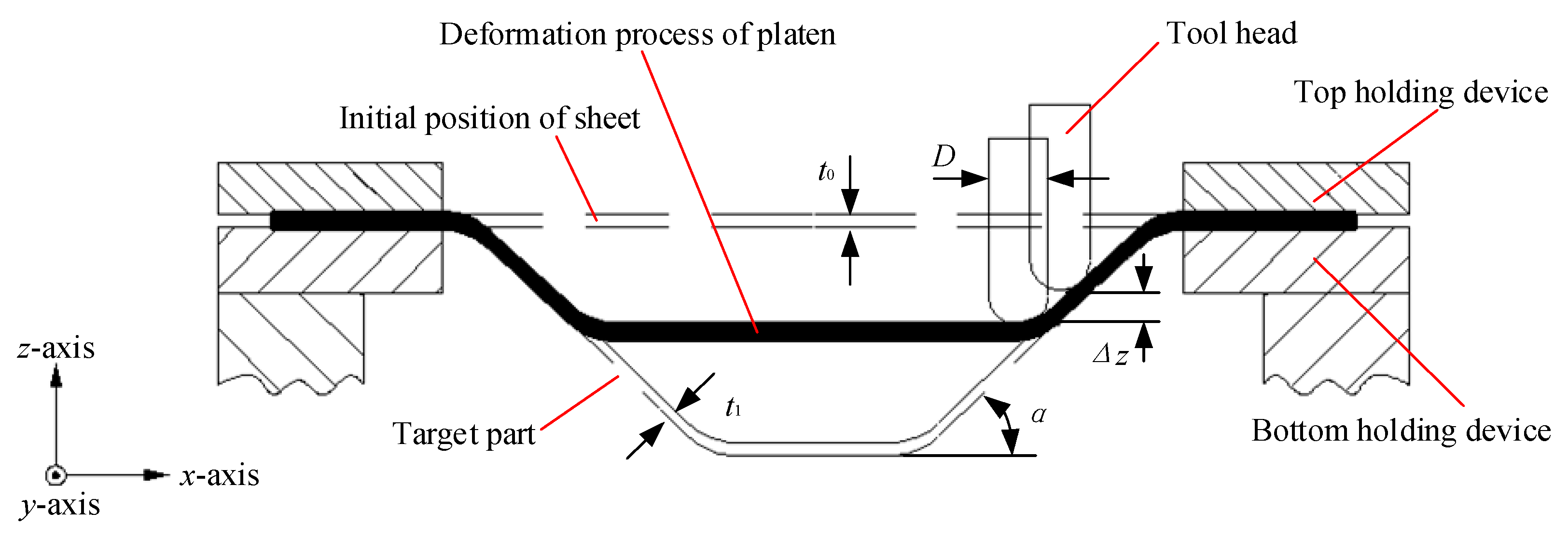
The forming principle of SPS-UV-SPIF technology is based on SPIF. To study the SPS-UV-SPIF, it is necessary to first understand the forming principle of the SPIF, as shown in
Figure 1. The sheet to be formed is suspended and held on the table of the machine tool by the top holding device and bottom holding device. The initial thickness of the sheet is
t0. The thickness of the target part after cumulative forming by the tool head of diameter
D is
t1. The layer spacing of layer-by-layer cumulative forming is
Δz. The forming angle of the target part is
α.
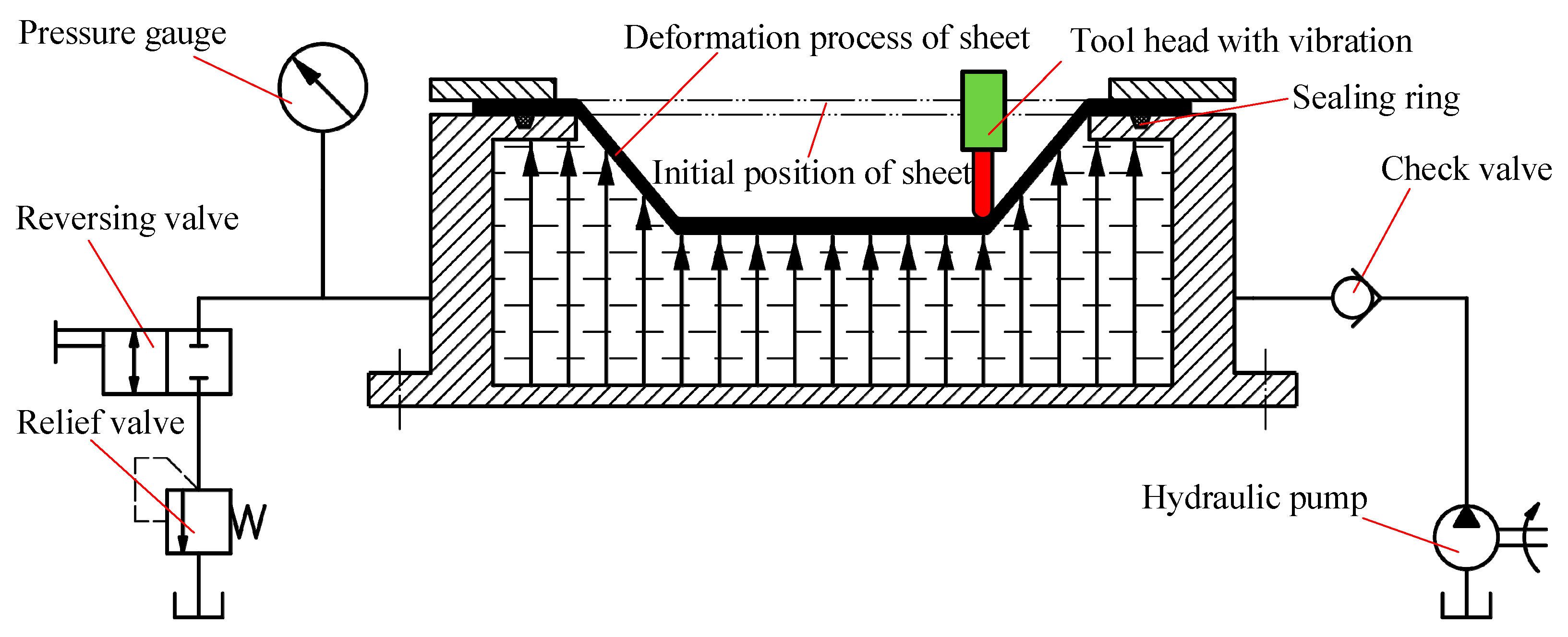
The forming principle of SPS-UV-SPIF technology is shown in
Figure 2. Based on the SPIF technology, the longitudinal UV is applied to the tool head. The back of the sheet is supported by the static pressure. Ultrasonic vibration is realized by an ultrasonic generator, a transducer, and an amplitude transformer. After the sheet material is subjected to the UV energy, the deformation ability and residual stress changes. This helps to improve the accuracy error caused by the springback of the part. The SPS is realized by a sealing ring, a relief valve, a hydraulic valve, a pressure gauge, a tank, and a check valve. The hydraulic oil in the tank is delivered to the seal holders by the hydraulic pump. The hydraulic oil under the action of the relief valve keeps the back support pressure of the entire forming process constant, which is equivalent to providing a flexible support for the forming sheet, as shown by the black arrows on the back of the sheet. This helps to improve the accuracy error caused by the suspended sheet.
4. Results and Discussion
It can be seen from the analytical model that the forming parameters affecting the radial force Fφ and the normal force Fr include the static pressure P, the amplitude A, the frequency f, the tool head radius R, the layer spacing Δz, the sheet thickness t, and the feed speed v2. In order to study the influence of various parameters on the forming force of SPS-UV-SPIF, the control variable method was used to compare the analytical results and experimental results. Thereby, the mechanism of the influence of each parameter on the forming force was analyzed and discussed.
In
Figure 9,
A = 0.03 mm,
f = 30 kHz,
R = 5 mm,
Δz = 1.0 mm,
t = 1 mm, and
v2 = 200 mm/min were constant, and the static pressure
P was variable. The variation laws of the forming forces with respect to the static pressure
P are obtained in theory and through experiments. The two trends are basically the same, and the relationship between static pressure
P, radial force
Fφ, and normal force
Fr in the analytical model is verified. As the static pressure
P increases, the supporting force on the back of the sheet becomes increasingly large, such that the radial force
Fφ and normal force
Fr increase with the increase of the static pressure
P. When the static pressure exceeds 0.07 MPa, excessive static pressure causes the sheet to undergo an upward pre-deformation. As a result, the tool head needs to overcome more deformation energy when forming the sheet, so the increase of the forming force becomes large. When the static pressure exceeds 0.11 MPa, the sheet will exhibit a very significant upward pre-deformation during the initial forming stage, which is disadvantageous for forming, as shown in
Figure 10. Therefore, the upper limit of the static pressure parameter is set to 0.1 MPa.
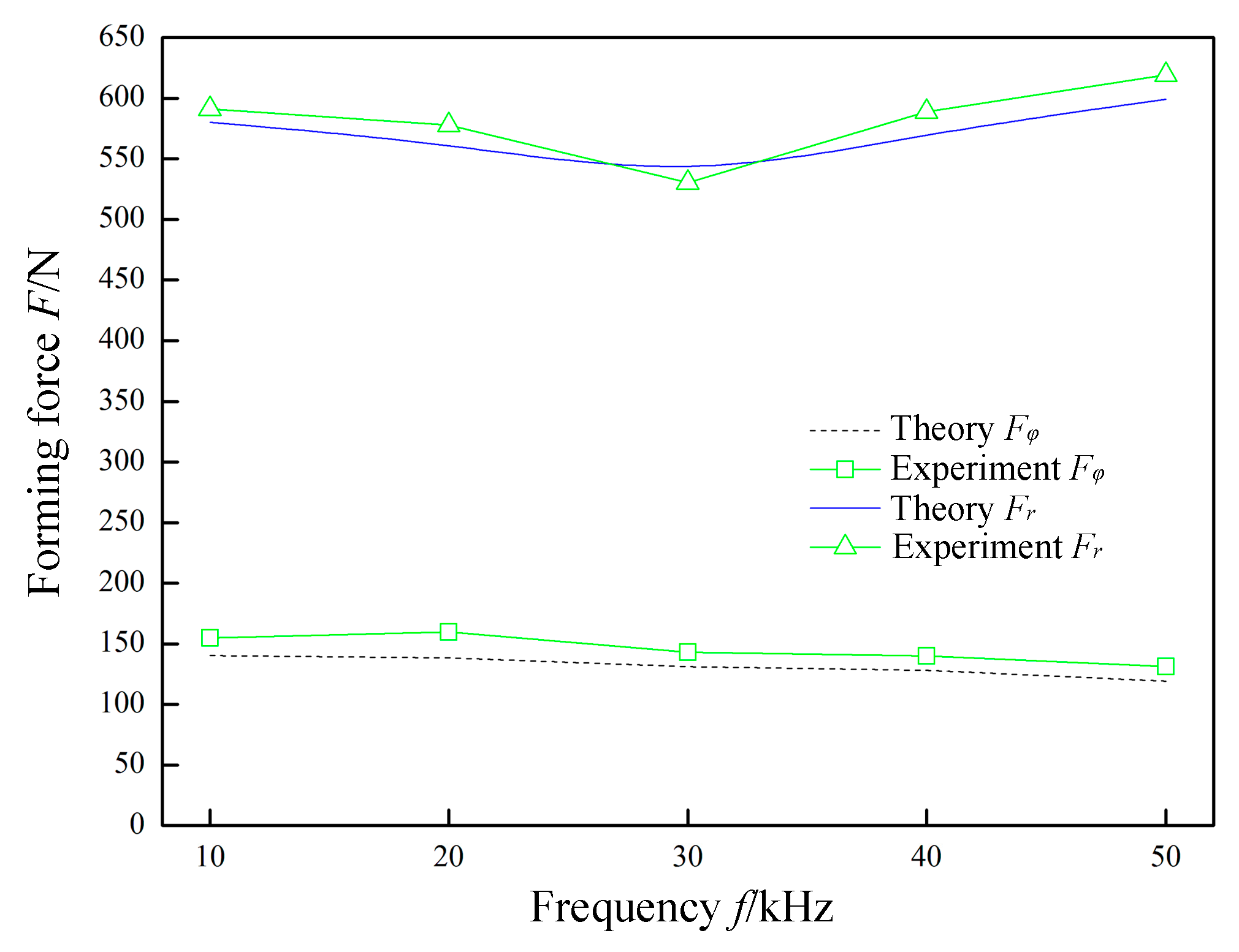
In
Figure 11,
P = 0.07 MPa,
A = 0.03 mm,
R = 5 mm,
Δz = 1.0 mm,
t = 0.8 mm, and
v2 = 200 mm/min were constant, and the frequency
f was variable. The variation laws of the forming forces with respect to the frequency
f are obtained in theory and through experiments. The normal force
Fr shows a nonlinear change with an increase in the frequency
f. This is because, when the frequency
f is lower than 30 kHz, as the frequency
f increases, the sheet is subjected to an increase in the impact density of the tool head. The material absorbs more ultrasonic energy, which in turn changes the rheological mechanism and structure evolution mechanism of the material. Macroscopically, the softening of the material and the forming limit are improved. At this time, the normal force
Fr decreases as the frequency
f increases. When the frequency
f is greater than 30 kHz, the instantaneous deformation of the sheet increases. More material participates in the deformation, which causes the corresponding normal force
Fr to increase as the frequency
f increases. However, the radial force
Fφ linearly decreases as the frequency
f increases. This is because, as the frequency
f increases, the single impact deformation amount also decreases linearly.
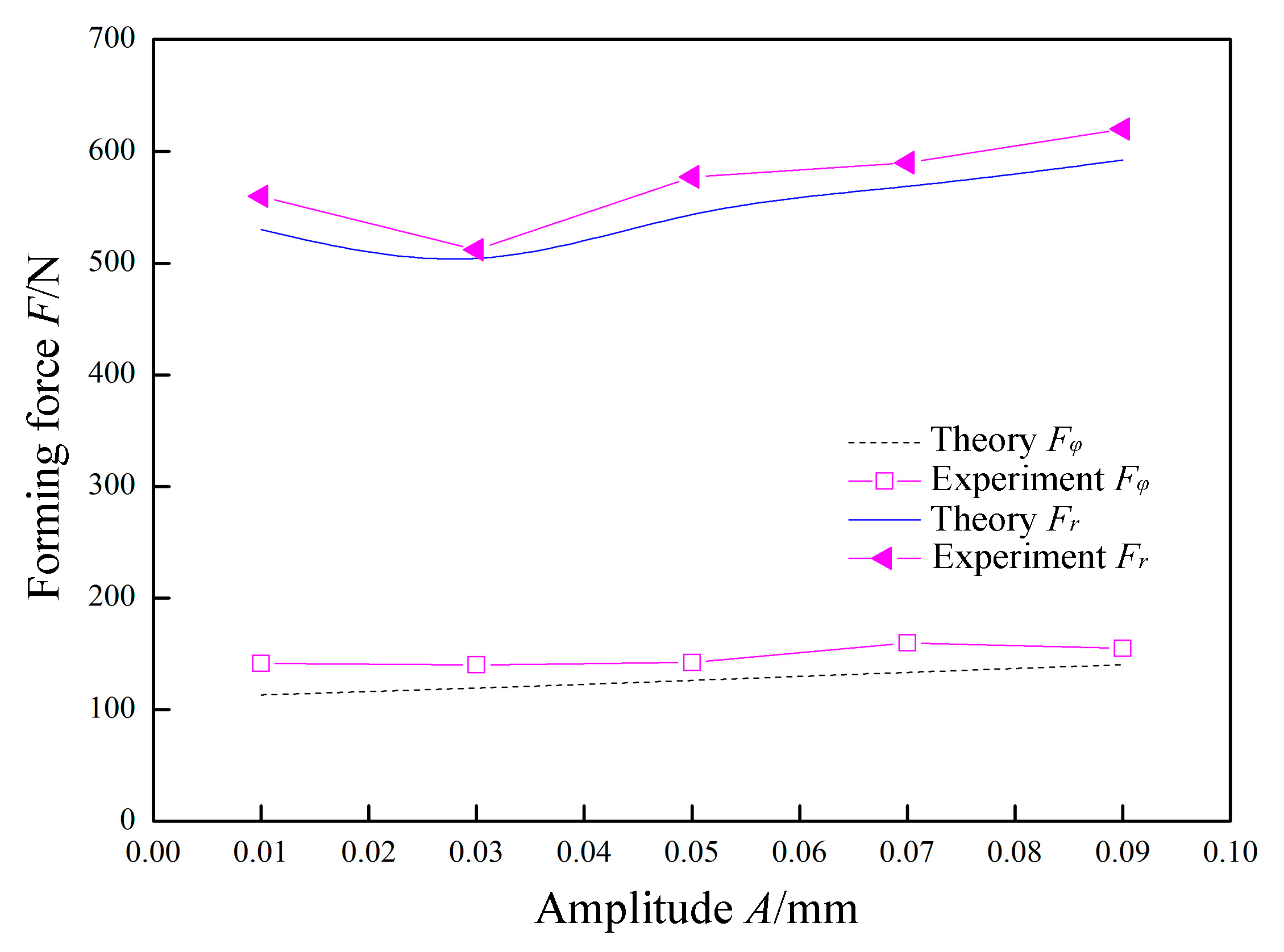
In
Figure 12,
P = 0.07 MPa,
f = 30 kHz,
R = 5 mm,
Δz = 1.0 mm,
t = 0.8 mm, and
v2 = 200 mm/min were constant, and the amplitude
A was variable. The variation laws of the forming forces with respect to the amplitude
A are obtained in theory and experiment. The normal force
Fr exhibits a nonlinear change with an increase in the amplitude
A. This is because, when the amplitude
A is lower than 0.03 mm, the impact of the tool head on the sheet is low. The yield limit of the material is not reached. At the moment when the tool head is separated from the sheet material, the upward springback of the sheet material causes the tool head to continuously contact the sheet, and the normal force
Fr is decreased. When the amplitude
A is around 0.03 mm, the impact of the tool head just exceeds the yield limit of the sheet material. The tool head is not subjected to continuous contact by the springback of the sheet when it is separated from the sheet. When the amplitude
A is larger than 0.03 mm, as the amplitude increases, the amount of deformation in the thickness direction of the sheet increases, and the corresponding normal force
Fr also increases. However, the radial force
Fφ increases linearly with the increase of the amplitude A. This is because the increase in amplitude accordingly causes the amount of radial deformation to linearly increase.
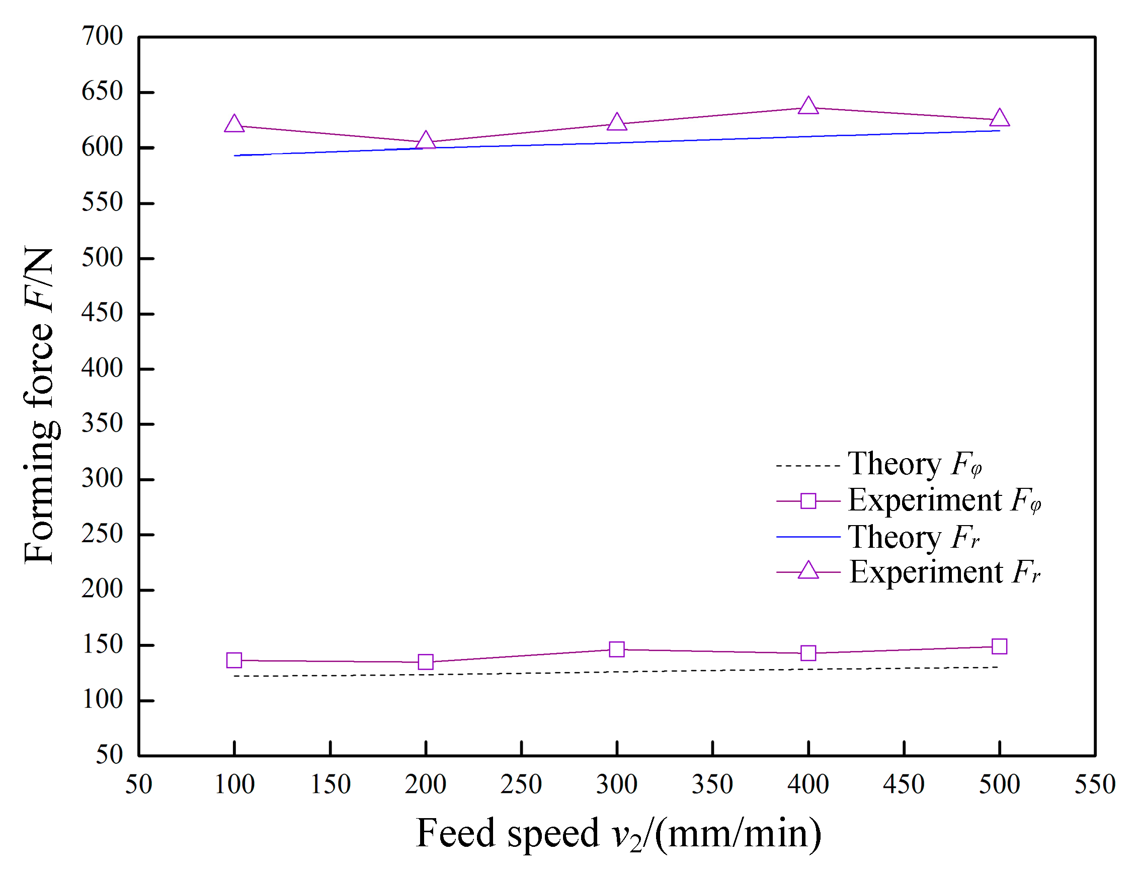
In
Figure 13,
P = 0.07 MPa,
A = 0.03 mm,
f = 30 kHz,
R = 5 mm,
Δz = 1.0 mm, and
t = 0.8 mm were constant, and the feed speed
v2 was variable. The variation laws of the forming forces with respect to the feed speed
v2 are obtained in theory and experiment. The normal force
Fr and the radial force
Fφ linearly increase as the feed speed
v2 increases, but the increase amplitude is low. Because the time required for the tool head to impact the sheet is very short, the change in feed speed
v2 does not substantially affect the amount of deformation of the sheet material by a single impact. Therefore, within the allowable range of actual forming, the feed speed
v2 should be increased as much as possible to improve the forming efficiency.
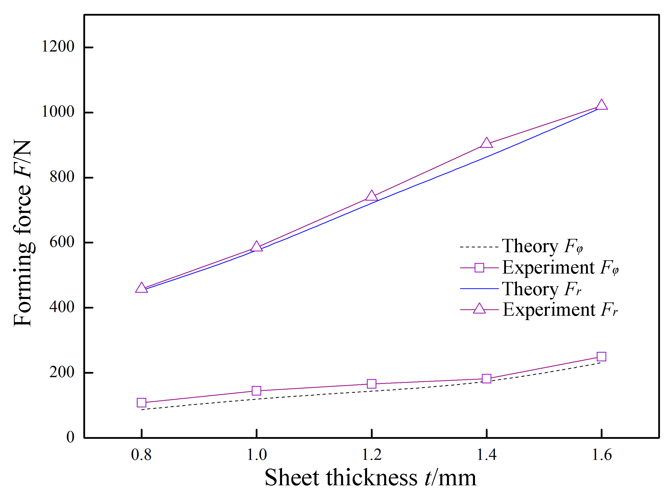
In
Figure 14,
P = 0.07 MPa,
A = 0.03 mm,
f = 30 kHz,
R = 5 mm,
Δz = 1.0 mm, and
v2 = 200 mm/min were constant, and the sheet thickness
t was variable. The variation laws of the forming forces with respect to the sheet thickness
t are obtained in theory and experiment. The normal force
Fr and the radial force
Fφ linearly increase as the thickness
t increases, and the increase amplitude is large. Since the other parameters are unchanged, increasing the sheet thickness
t is equivalent to increasing the deformation resistance. That is, the forming force is increased.
In
Figure 15,
P = 0.07 MPa,
A = 0.03 mm,
f = 30 kHz,
R = 5 mm,
t = 0.8 mm, and
v2 = 200 mm/min were constant, and the layer spacing
Δz was variable. The variation laws of the forming forces with respect to the layer spacing
Δz are obtained in theory and experiment. Both the normal force
Fr and the radial force
Fφ linearly increase as the layer spacing
Δz increases. This is because increasing the layer spacing
Δz causes a larger amount of sheet deformation. The increase amplitude is less than the increase amplitude caused by the sheet thickness
t, and is higher than the increase amplitude caused by the feed speed
v2. The excessive
Δz will cause bending and springback of the part, and a
Δz value that is too low will reduce the forming efficiency. Therefore, the use of a suitable
Δz at different characteristics can improve the forming efficiency while maintaining the quality of the part.
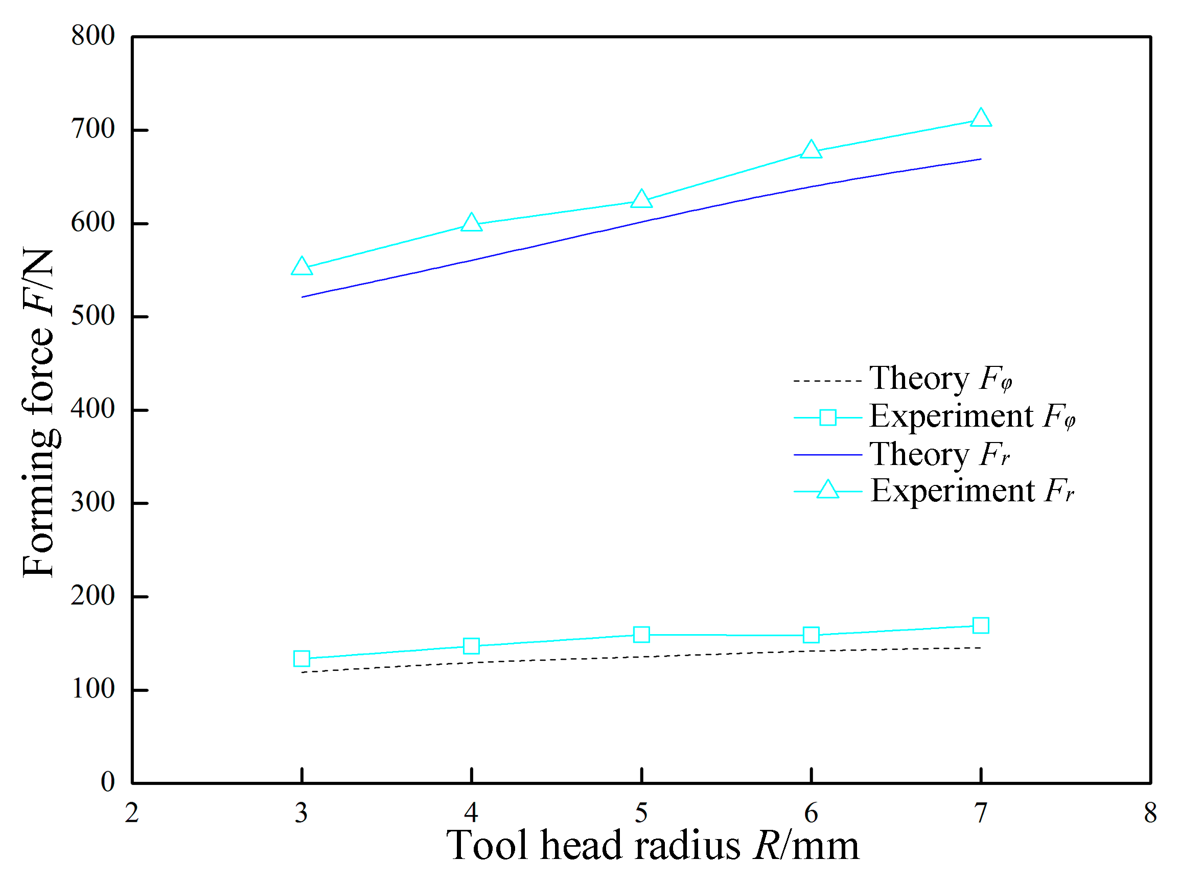
In
Figure 16,
P = 0.07 MPa,
A = 0.03 mm,
f = 30 kHz,
Δz = 1.0 mm,
t = 0.8 mm, and
v2 = 200 mm/min were constant, and the tool head radius
R was variable. The variation laws of the forming forces with respect to the tool head radius
R are obtained in theory and experiment. Both the normal force
Fr and the radial force
Fφ linearly increase as the tool head radius
R increases. This is because increasing the tool head radius
R increases the amount of deformation of the sheet. In the forming process, an
R value that is too high is not conducive to the formation of complex parts, and an
R value that is too low is likely to cause stress concentration. Therefore, the dimension of the tool head should be selected according to the actual forming characteristics.
5. Conclusions
This paper proposes a new type of SPS–UV SPIF technology that can improve the accuracy of parts. In order to study the technology in depth, the mechanical analysis model was established and analyzed based on the forming principle and the motion rule. Finally, the analytical model was verified by the corresponding experiments, and the following conclusions were obtained:
(1) According to the analytical model, it can be seen that the normal force Fr and the radial force Fφ are related to the static pressure P, the amplitude A, the frequency f, the tool head radius R, the layer spacing Δz, the sheet thickness t, and the feed speed v2. There is also a difference in their degree of relevance.
(2) According to the comparison between the experimental results and the theoretical results, it was found that the actual variation trend of the normal force Fr and the radial force Fφ with respect to each parameter tends to be consistent with the theoretical results, which confirms the correctness of the analytical model.
(3) According to the analysis results, the effects of static pressure parameters and vibration parameters on the forming force are nonlinear. As the static pressure increases, the normal force Fr does not continue to increase linearly. When the static pressure exceeds 0.07 MPa, the sheet will have an upward pre-deformation, resulting in a sudden increase in the forming force. When the amplitude A is around 0.03 mm, the impact force of the tool head just exceeds the yield limit of the sheet material and the forming force at this time is the lowest. When the frequency f is around 30 kHz, the softening effect of the material is best and the forming force at this time is the lowest.


