The Size Effect of TiO2 Hollow Microspheres on Photovoltaic Performance of ZnS/CdS Quantum Dots Sensitized Solar Cell


1
Institute of Flexible Composite Materials, College of Chemistry and Chemical Engineering, Hexi University, Zhangye 734000, China
2
Key Laboratory of Hexi Corridor Resources Utilization of Gansu, Hexi University, Zhangye 734000, China
*
Author to whom correspondence should be addressed.
Materials 2019, 12(10), 1583; https://doi.org/10.3390/ma12101583
Submission received: 15 April 2019
/
Revised: 10 May 2019
/
Accepted: 13 May 2019
/
Published: 15 May 2019
(This article belongs to the Special Issue Advanced Materials for Photonics and Photovoltaics Applications)
Abstract
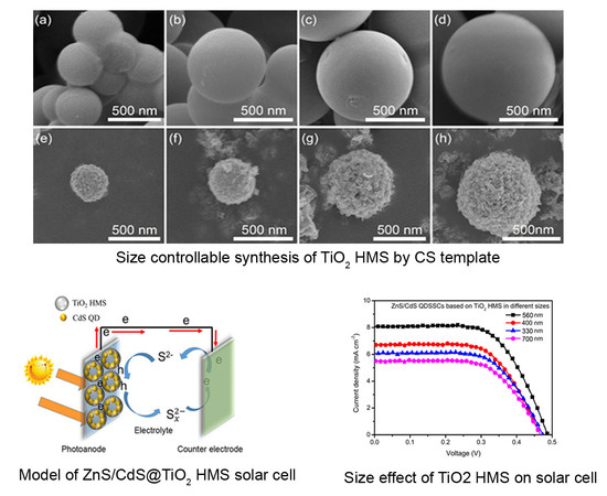
:Size controllable TiO2 hollow microspheres (HMS) were synthesized by a carbonaceous spheres (CS) template method. Based on TiO2 HMS, the ZnS/CdS quantum dots (QDs) were loaded to form a ZnS/CdS@TiO2 HMS photoanode for quantum dots sensitized solar cell (QDSSC). The size effects of TiO2 HMS on photovoltaic performance were investigated, and showed that TiO2 HMS with sizes ~560 nm produced the best short-circuit current density (Jsc) of 8.02 mA cm−2 and highest power conversion efficiency (PCE) of 1.83%, showing a better photovoltaic performance than any other QDSSCs based on TiO2 HMS with size ~330 nm, ~400 nm, and ~700 nm. The improvement of photovoltaic performance based on ~560 nm TiO2 HMS which can be ascribed to the enhanced light harvesting efficiency caused by multiple light reflection and strong light scattering of TiO2 HMS. The ultraviolet-visible (UV-vis) spectra and incident photo to the current conversion efficiency (IPCE) test results confirmed that the size of TiO2 HMS has an obvious effect on light harvesting efficiency. A further application of ~560 nm TiO2 HMS in ZnS/PbS/CdS QDSSC can improve the PCE to 2.73%, showing that TiO2 HMS has wide applicability in the design of QDSSCs.
1. Introduction
Hollow micro-spherical structures of metal oxide materials have attracted much attention due to their broad range of applications in vehicles for the controlled release of substances, catalysis, photonic devices, and energy [1,2]. Especially in energy-related systems, various metal oxide hollow microspheres (HMS) such as TiO2, ZnO, and Fe2O3 have been used in photocatalysis, dye or quantum dots sensitized solar cells, lithium ion batteries, sensors, and supercapacitors [3,4,5]. It is well known that the hollow spherical structure is capable of providing an enhanced surface-to-volume ratio and a reduced transport length for both mass and charge transport [6,7,8]. Among these types of metal oxide HMS, TiO2 HMS has become one of the hot topics in research, particularly in solar energy conversion devices such as dye sensitized solar cells (DSSCs) or quantum dots sensitized solar cells (QDSSCs).
TiO2 can function as a supporting architecture in DSSCs or QDSSCs because of some intrinsic material characteristics, including chemical and optical stability, low fabrication cost, high electron mobility, and matched band alignment to sensitizers [9,10,11,12]. In addition, hollow spherical structures of TiO2 are believed to have the advantages of low bulk density, high specific surface area, and good surface permeability in DSSCs or QDSSCs [13]. Although various shapes of TiO2 structures such as nanotubes, nanorods, mesoporous beads, and microspheres have been used to tailor the optical and electronic properties of photoanodes in DSSCs or QDSSCs [8,14,15,16]. TiO2 HMS is believed to have outstanding advantages in enhancing light harvesting efficiency due to the multiple reflections of incident light within the interior cavity of HMS.
Until now, several approaches such as the Ostwald-ripening formation mechanism and template-assisted method have been developed for the synthesis of TiO2 HMS [17]. The Ostwald-ripening formation mechanism is widely reported in the solvothermal or hydrothermal process to produce TiO2 HMS: however, getting the size uniform to TiO2 HMS remains a challenge by this mechanism. The template-assisted method seems better for the controllable synthesis of HMS [18,19]. Carbonaceous spheres are preferred due to their functional groups on the surface and their easy removal by the heating process in air [20]. Furthermore, the size of TiO2 HMS from small to big can be well tuned using carbonaceous sphere templates of different sizes. In DSSCs or QDSSCs, the TiO2 HMS as the architecture of photoanodes shows potential in improving photovoltaic performance. Yong et al. reported a type of DSSC with a power conversion efficiency of 9.50% based on TiO2 HMS with a size around 500–700 nm [21]; their TiO2 HMS can generate a strong light scattering, leading to better light harvesting efficiency than TiO2 nanoparticles. A similar conclusion also was echoed in DSSCs by Jiang et al. using their Au@TiO2 HMS with sizes around ~500 nm, their DSSC achieved a power conversion efficiency of 7.81% which obtained a 30% increment of power conversion efficiency in comparison to conventional DSSCs fabricated with P25 TiO2 photoanodes [22]. However, these investigations of TiO2 HMS in solar cells almost focused on comparing the conventional TiO2 nanoparticles. The systematic research about the size effect of TiO2 HMS on photovoltaic performance seems to have been neglected. In fact, the size effect is important because it is generally known that strong light scattering should occur only when the size of a sphere is comparable to the wavelength of incidental light [23,24,25]. Therefore, the different sizes of TiO2 HMS have been synthesized by us to serve as supporting architectures in ZnS/CdS QDSSCs, and their size effect on photovoltaic performance has been investigated. To our best knowledge, this kind of inspiration reveals that the size effect of TiO2 HMS on QDSSCs’ performance has not been widely reported and may provide insights into the design of highly efficient QDSSCs from the perspective of supporting architectures.
2. Materials and Methods
2.1. Materials
Sucrose, titanium tetrachloride, ethylcellulose, terpineol, ethanol, cadmium nitrate, zinc nitrate, sodium sulfide, and sulfur powder were purchased from Aladdin Co., Ltd.; all these solvents and chemicals were of analytical grade and used without further purification. The fluorine-doped tin oxide (FTO) conductive glass was purchased from Opvtech Co., Ltd. Deionized water was used throughout the experiments.
2.2. Preparations of Carbonaceous Spheres (CS) Template
The carbonaceous spheres (CS) template were hydrothermally synthesized with sucrose aqueous solution similar to the previous report in [13]. In a typical synthetic route, sucrose aqueous solution was sealed in a Teflon stainless autoclave for 8 h at 180 °C. Then, the acquired black precipitate was washed with deionized water three times and dried in an oven for 12 h at 80 °C. In order to get CS templates with different sizes, the concentrations of sucrose solution were adjusted to 0.5 M, 0.75 M, 1.0 M, and 1.5 M, respectively.
2.3. Size Controllable Synthesis of TiO2 Hollow Microspheres (HMS)
Based on CS templates, TiO2 hollow microspheres (HMS) were further synthesized. Briefly, 5 g CS template were dispersed in 3 M TiCl4 aqueous solution (100 mL) which was pre-prepared by dropping TiCl4 into a deionized ice bath. After 10 min, magnetic stirring and a subsequent 20 min ultrasonication, the mixture was aged for 6 h at room temperature. The mixture was filtered and washed three times, and was transferred into oven drying at 80 °C for 12 h. The dried black product was heated in Muffle furnace with rate of 4 °C/min to 500 °C, and holding at this temperature for 4 h, producing white TiO2 HMS powder. The TiO2 HMS with a size from small to big were controllably synthesized using different sizes of CS template.
2.4. Fabrication of ZnS/CdS@TiO2 HMS Photoanode
The first step is to construct TiO2 HMS on FTO glass as follows. The viscous mixture containing TiO2 HMS powder (3.0 g), ethylcellulose (0.5 g), ethanol (5 mL), and terpineol (10 mL) was under magnetic stirring for 1 h, and was used as a paste to cover the conductive surface of FTO glass (2.0 cm × 1.5 cm) by the doctor-blade technique; the thickness of the TiO2 HMS film on FTO glass was controlled to be ~15 μm, and the active area was adjusted to 0.25 cm2 by a spacer with corresponding area and thickness; after being dried at room temperature, the photoanode was heated to 450 °C for 1 h to remove any organic residuals, forming TiO2 HMS photoanodes.
The second step is the fabrication of ZnS/CdS@TiO2 HMS photoanode by the classic successive ionic layer adsorption and reaction (SILAR) method [26,27]. In general, 0.05 M cadmium nitrate solution was prepared by mixing methanol and deionized water (7:1, V/V) as a Cd2+ source, and 0.05 M sodium sulfide solution was prepared with a mixed solution of methanol and deionized water (1:1, V/V) as a S2− source. The TiO2 HMS photoanode was first immersed in Cd2+ solution for 30 s, washed with methanol and dried by air gun. Then dipping the photoanode into S2− solution for another 30 s, washed and dried again. These two procedures were defined as one SILAR cycle, and 8 SILAR cycles were repeated on TiO2 HMS photoanode to guarantee enough CdS QDs loadings. Similarly, two SILAR cycles of ZnS were covered on CdS QDs as passivation layers to form ZnS/CdS@TiO2 HMS photoanodes with the purpose to enhance the stability of the photoanode [28]. In order to investigate the size effect of TiO2 HMS on photovoltaic performance, identical SILAR cycles of ZnS/CdS QDs were loaded on TiO2 photoanodes which were constructed by different sizes of TiO2 HMS.
2.5. Solar Cell Assembly
Cu2S film formed on a brass sheet was employed as a counter electrode, which was prepared according to a previous report [29]. Brass foil with size of 2.0 cm × 1.5 cm and thickness of 0.3 mm was first etched in HCl solution at 80 °C for 15 min to the exposure of copper. Following a wash with deionized water and drying by air gun, the etched brass foil was immersed in polysulfide solution which is composed of 1M sodium sulfide and 1M sulfur in deionized water, causing the exposure surface of etched brass foil to turn black. This color change demonstrated the formation of Cu2S. To fabricate QDSSC, the ZnS/CdS@TiO2 HMS photoanode and Cu2S counter electrode were clipped together like a sandwich for the open I-V test, to which one drop of polysulfide electrolyte was filled between the photoanode and the counter electrode as a scavenger of holes. The QDSSCs based on TiO2 HMS with different sizes were constructed to proceed the contrastive study of size effect of TiO2 HMS on photovoltaic performance of QDSSCs. To further explore if other QD systems are suitable for TiO2 HMS, the ZnS/PbS/CdS QDSSC (two SILAR cycles of PbS QDs) were also fabricated by a similar approach [29]. Each of the QDSSCs were repeatedly tested three times in order to guarantee their reproducibility.
3. Characterization
The surface morphological images of samples were captured by Quanta 450 FEG scanning electron microscopy (SEM, Hillsbro, OR, USA) equipped with an energy dispersive X-ray spectrometer (EDS) for surface elemental mapping analysis. The Tecnai G2 F20 transmission electron (TEM, Hillsboro, TX, USA) equipped with EDS components was employed to record the fine structure and elemental spot scanning of samples. The Nicolet_iS50 infrared spectrometer (IR, Thermo Fisher Scientific, CN) is used to analyze the functional groups of carbonaceous spheres. The crystal phase of TiO2 HMS was analyzed by D/MAX-2400 Rigaku X-ray diffraction (XRD, Rigaku, Japan). The Nitrogen adsorption-desorption isotherm and BET surface area analysis were conducted by Tirstar II 3020 to monitored the influence of size variation of TiO2 HMS on QDs loadings.
The J-V behaviors of QDSSCs assembled with ZnS/CdS@TiO2 HMS photoanodes were investigated by Oriel I-V test station (Newport, USA). The sunlight illumination with an intensity of 100 mW cm−2 was simulated by a solar simulator. The incident photo to the current conversion efficiency (IPCE) was monitored by a 150 W Xe lamp coupled with a computer controlled monochromator.
4. Results and Discussion
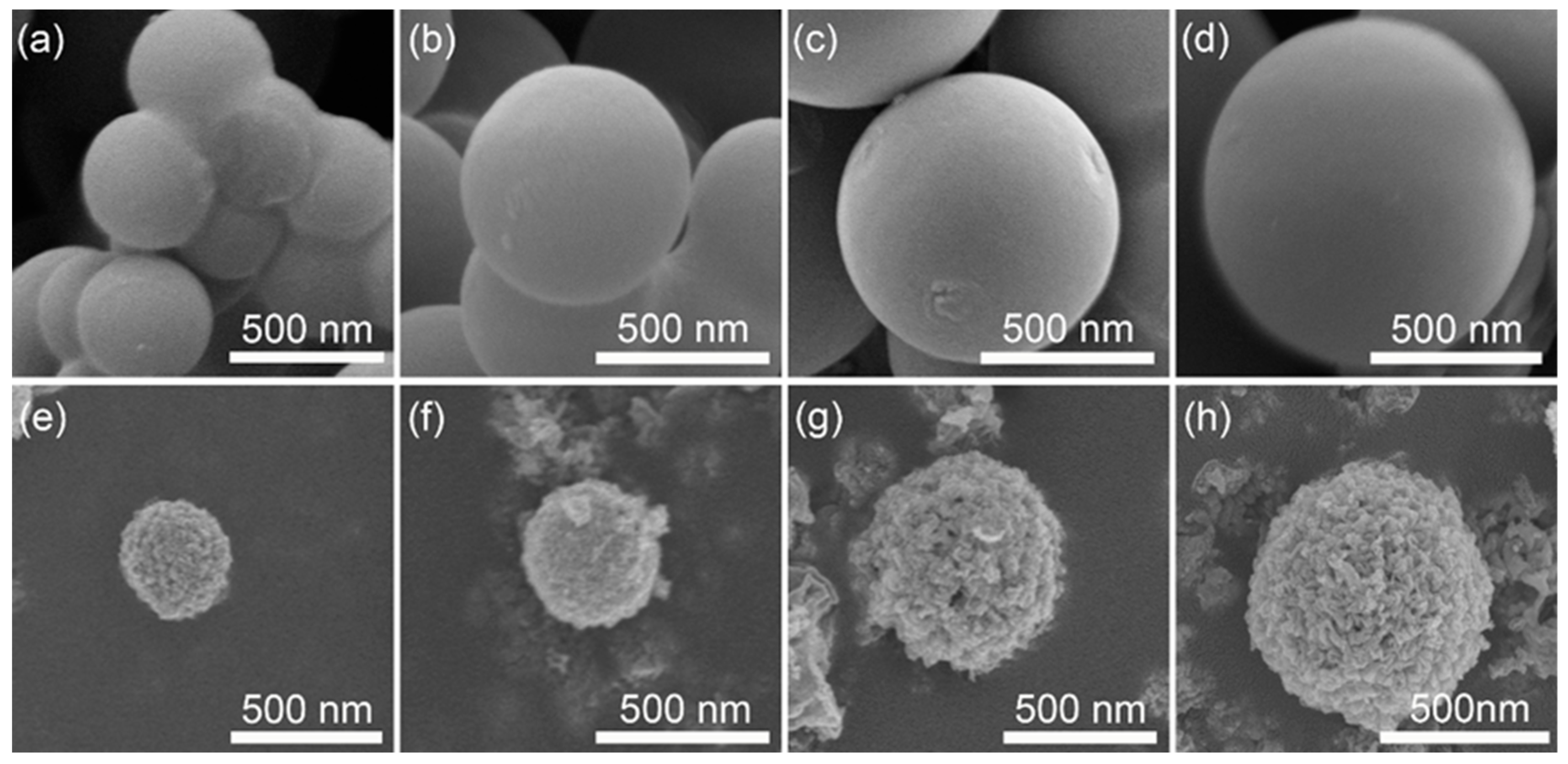
The size adjustability of CS is one of the most important factors in order to synthesize TiO2 HMS with different sizes. As a facile method, the size of CS can be easily varied by changing the concentration of sucrose aqueous solution when a hydrothermal process is conducted. Figure 1a–d displays the size changes of the resultant CS according to the increase of sucrose concentration. Apparently, the CS are well obtained by this hydrothermal process, and the size of CS increases from ~380 nm to ~1000 nm as the increment of sucrose concentration increases from 0.5 M to 1.5 M. Another key factor for the fabrication of TiO2 HMS is the adsorption ability of CS for Ti4+. According to a previous report [13,30], the hydrophilic groups that distribute on the surface of the CS template are favorable to the adsorption of metal ions. The IR spectrum of CS is presented in Figure S1 (Supplementary Figure S1), showing that the surface of CS contains OH, C–O, and C=O groups, which provide the sites for the anchoring of Ti4+).
Based on the CS template, TiO2 HMS are further obtained, which are shown in Figure 1e–h. In general, the surface of TiO2 HMS is rougher than their CS template, indicating that the TiO2 HMS are assemble by large numbers of nanoparticles. Moreover, the size of TiO2 HMS increases as larger CS template are employed, confirming that this method is feasible for the controllable synthesis of TiO2 HMS. A shrinkage phenomenon can be observed by a careful comparison between TiO2 HMS and their corresponding CS template. Taking Figure 1d,h as an example, the size of the CS template is ~1000 nm, however the product of TiO2 HMS is ~700 nm, of which ~30% shrinkage occurred after the formation of TiO2 HMS. Similar results are also observed in previous reports [18,19,31]. Therefore, TiO2 HMS with size distributions from ~330 nm, ~400 nm, ~560 nm, and ~700 nm are acquired by gradually increasing the CS template size.
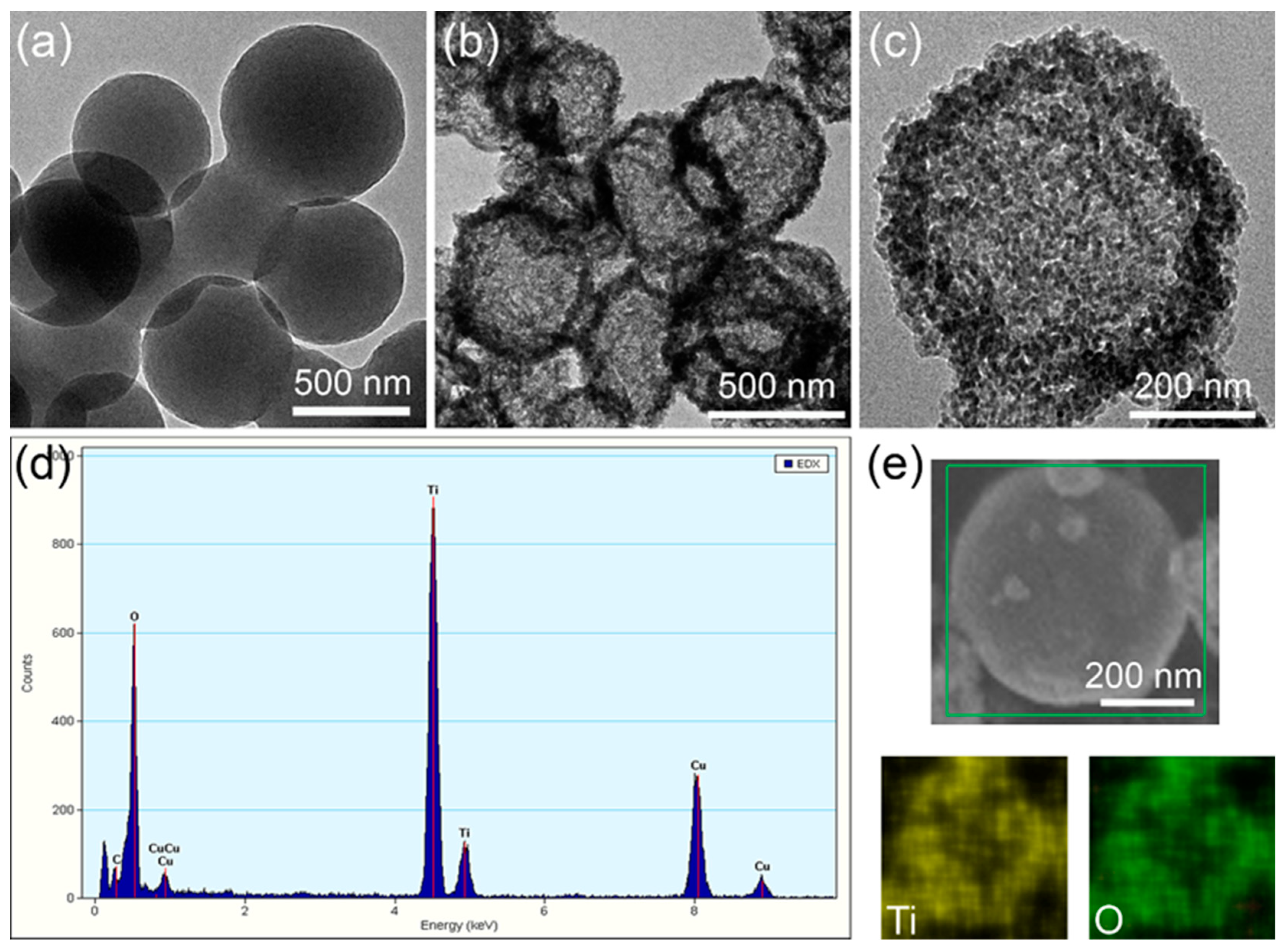
Although the spherical structure of TiO2 can be identified by SEM images from the resultant product, it seems that claiming the TiO2 structure belongs to the hollow microsphere is still insufficient with respect to direct proofs. Therefore, the TEM is used to present the fine structure of the products, which are shown in Figure 2a–c. Figure 2a shows the TEM image of the CS template, displaying a solid sphere structure. Obvious hollow spherical structures are obtained after soaking the CS template in Ti4+ solution and a subsequent annealing process, as shown Figure 2b, confirming that CS template method is a feasible approach to fabricate TiO2 HMS. Figure 2c presents a single TiO2 HMS in larger magnification, which shows that the shell of a hollow sphere is composed of a large number of nanoparticles, demonstrating that Ti4+ precursors adsorbed by the CS template were gradually turned into TiO2 nanoparticles and aggregated on the surface of the CS template during the annealing process, and finally led to the shell of a hollow microsphere. The EDS in Figure 2d evidenced the elemental composition of HMS, showing two sharp peaks which represent O and Ti elements, respectively. Further elemental mapping scan results from the SEM of HMS as shown in Figure 2e display that O and Ti elements are uniformly distributed on the surface of HMS, confirming the hollow microspherical structure is TiO2.
The crystal structure of TiO2 HMS is analyzed by XRD, which is shown in Figure S2 (Supplementary Figure S2). Several sharp diffraction peaks can be discerned in this XRD pattern, especially peaks that appeared around 2θ = 25.2°, 37.8°, 48.0°, 53.7°, and 71.4° which can be ascribed to the (101), (004), (200), (105), and (220) planes of the tetragonal anatase phase according to JCPDS Card No. 21-1272. The sharpening of diffraction reflections suggests their relative strong crystallinity due to the 500 °C calcination temperature used in the production of TiO2 HMS. As the SEM, TEM, EDS, and XRD analysis results showed, it can be concluded that anatase TiO2 HMS with different size distributions can be controllably fabricated by the CS template method.
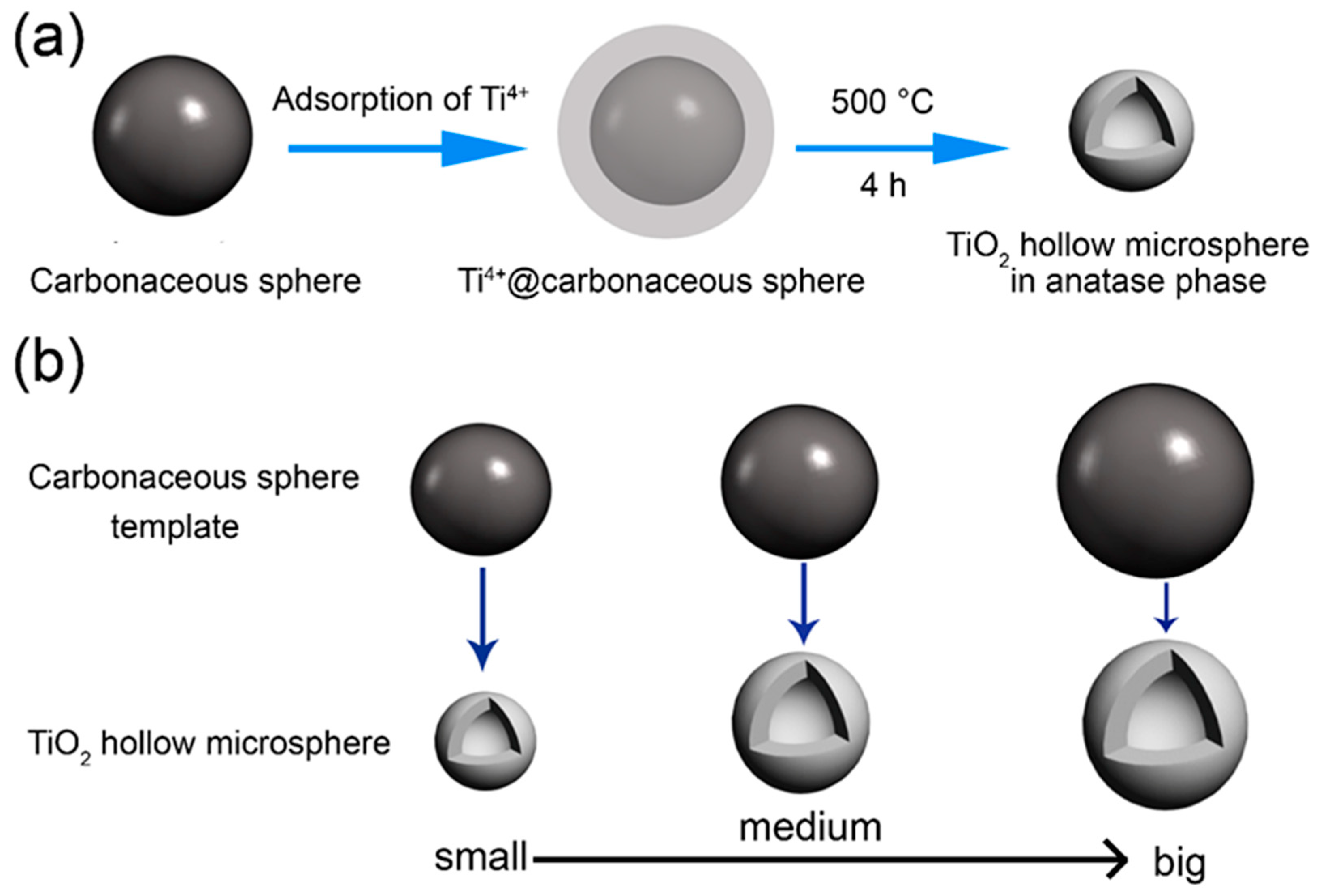
The formation and size controllable synthesis mechanisms of anatase TiO2 HMS are illustrated in Figure 3 according to the experimental process and characterization results. The most important part in the fabrication process is the CS templates. As indicated by Figure S1, the surface of CS templates is rich with carboxyl and hydroxyl groups, which are beneficial to the adsorption of Ti4+ [13]. As presented in Figure 3a, initially the CS template is dispersed in Ti4+ precursors for 6 h to adsorb Ti4+ ions on its surface, leading to the formation of Ti4+@carbonaceous sphere. Subsequently, the carbonaceous sphere turns to CO2 during the annealing process. In the meantime, the Ti4+ ions adsorbed on the surface of the carbonaceous sphere are oxidized to anatase TiO2 nanoparticles which are assembled according to the shell of the hollow sphere, leading to the formation of TiO2 HMS. Furthermore, if different sizes of the CS template are selected, the size controllable synthesis of TiO2 HMS can be realized as illustrated in Figure 3b.
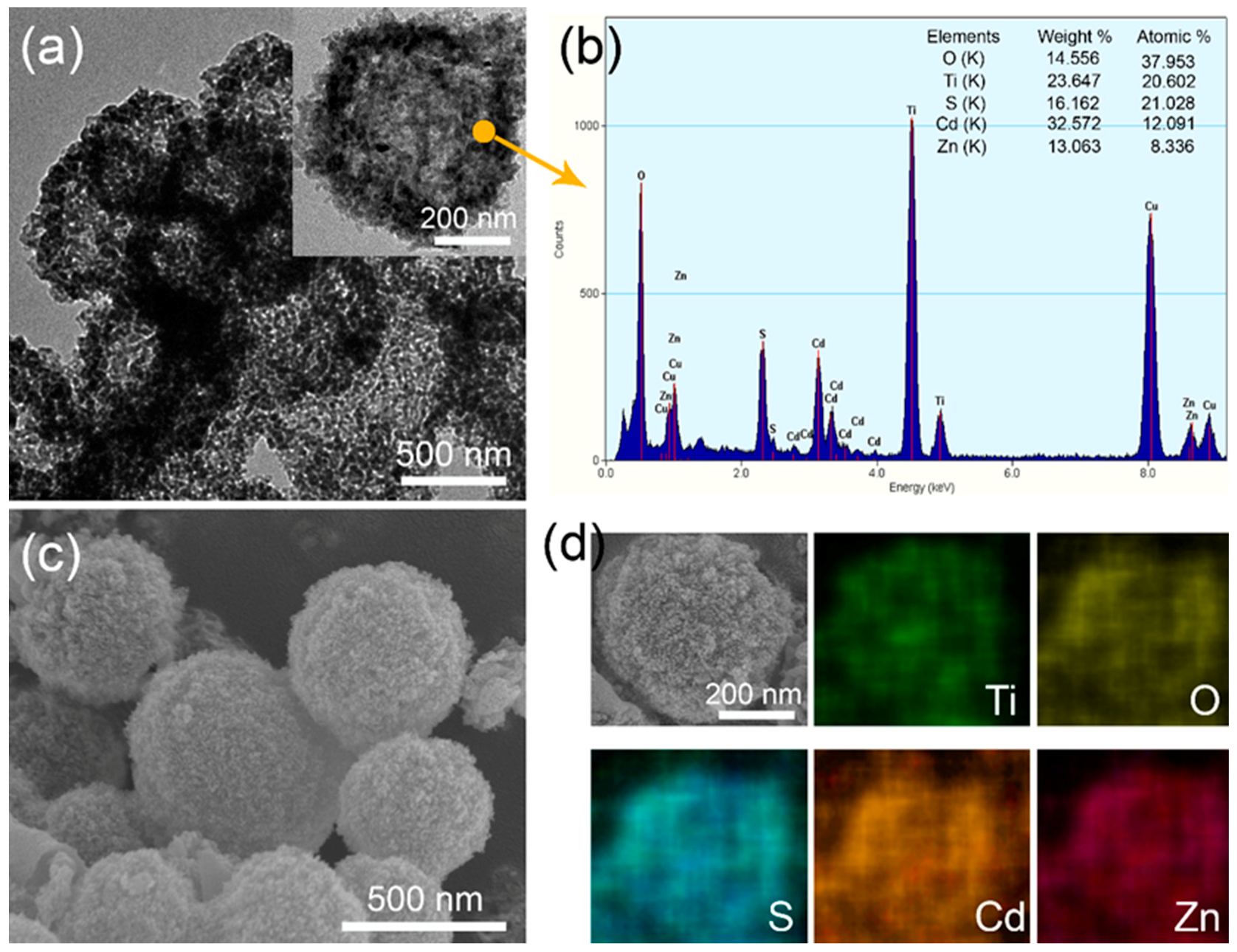
Based on TiO2 HMS, the ZnS/CdS QDs have been anchored onto the surface by the SILAR method. The morphological variations of HMS have been revealed by TEM and SEM images. Figure 4a shows the TEM of ZnS/CdS@TiO2 HMS, displaying that the hollow spherical structure still preserves well but with a thicker thickness of the shell. With a magnified TEM in the inset of Figure 4a, it can be discerned that many small nanoparticles assembled on the shell of TiO2 HMS, making the shell’s thickness thicker than bare TiO2 HMS which is shown in Figure 2c; this implies that ZnS/CdS QDs are successfully anchored onto the shell of TiO2 HMS. The EDS result of a selected spot of ZnS/CdS@TiO2 HMS is shown in Figure 4b. Excepting the Ti and O elements contributed by the TiO2 HMS supporting architectures, other peaks including Zn, Cd, and S can be discerned in EDS, and it is worth noting is that the atomic ratio of (Zn+Cd): S is very close to 1:1, which indicates the successful decoration of ZnS/CdS QDs on TiO2 HMS. Similar phenomena can also be identified by the SEM image of ZnS/CdS@TiO2 HMS in Figure 4c. After sensitization with ZnS/CdS QDs, many smaller nanoparticles were covered on the surface of TiO2 HMS, which cannot be observed in SEM images of bare TiO2 HMS shown in Figure 1e–h. The SEM elemental mapping scan results on the surface of HMS in Figure 4d show that Zn, Cd, S, O and Ti elements are homogenously distributed on the surface of HMS, also confirming the formation of ZnS/CdS@TiO2 HMS. Hence, ZnS/CdS QDs sensitized TiO2 HMS with different sizes are investigated in contrast to find out the size effect of TiO2 HMS on the photovoltaic performance of ZnS/CdS QDSSCs.
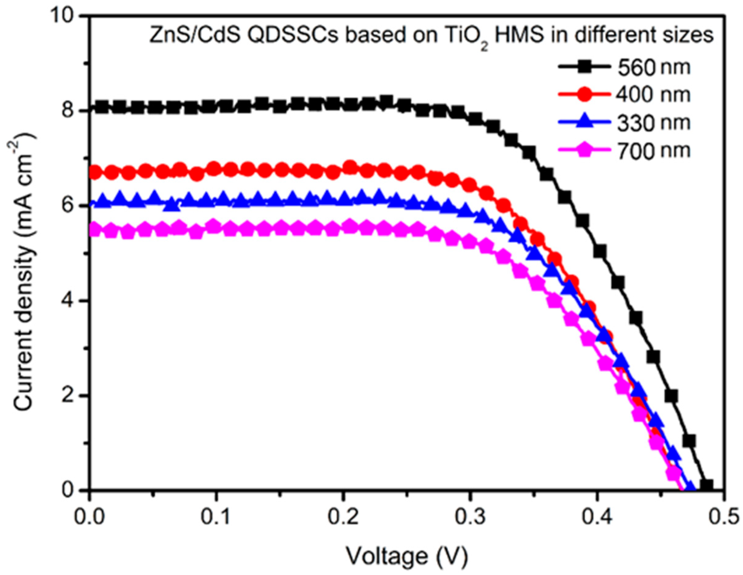
Figure 5 compares the best J-V curves of ZnS/CdS QDSSCs based on TiO2 HMS supporting architecture with different sizes (the best J-V curves were selected from three times repeated tests of these solar cells, See Supplementary Materials, Figure S4). The corresponding parameters of these solar cells, including open-circuit voltage (Voc), short-circuit current density (Jsc), fill factor (FF), and power conversion efficiency (PCE), are summarized in Table 1. The ZnS/CdS@TiO2 HMS solar cell with a size ~330 nm shows a Voc of 0.47 V, a Jsc of 6.23 mA cm−2, and a FF of 0.46, producing a PCE of 1.34%. The size increment of TiO2 HMS seems beneficial to improve photovoltaic performance. For example, the ZnS/CdS QDSSC based on TiO2 HMS with size ~400 nm presents a Voc of 0.46 V, a Jsc of 6.86 mA cm−2, and a FF of 0.47, leading to PCE increases to 1.48%. The highest PCE of 1.83% among our series sample solar cells is achieved by TiO2 HMS with size ~560 nm, showing a Voc of 0.49 V, a Jsc of 8.02 mA cm−2, and a FF of 0.47. However, a further increment of size to ~700 nm results in a decrease of PCE to 1.18%, which is mainly caused by the decrease of Jsc to 5.44 mA cm−2. In our series of QDSSCs, both the preparation method of ZnS/CdS QDs and the SILAR cycles on TiO2 HMS are the same; the only difference among these QDSSCs is the size of the TiO2 HMS supporting architecture, which may influence the QDs loadings and light utilization. Figure S3 (Supplementary Figure S3) shows the BET results of the smallest and largest TiO2 HMS of our series samples, it can be seen that the size increment of HMS from ~330 nm to ~700 nm did not lead to an obvious variation of BET surface area, meaning that the size of TiO2 HMS has little contribution to enhance QDs loadings. Therefore, it is believed that the size change of TiO2 HMS is a key factor responsible for the variation of photovoltaic performance, especially for Jsc’s variation.
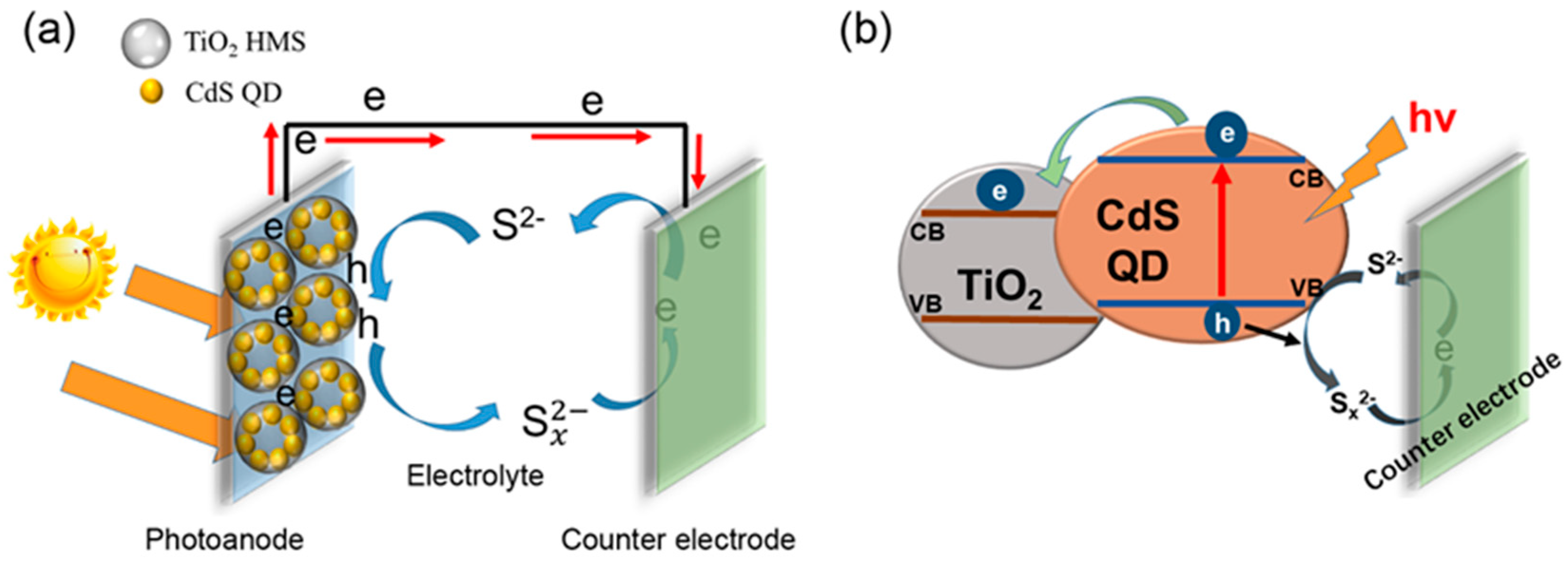
Figure 6a,b presents the basic model and charge transport mechanism of ZnS/CdS@TiO2 HMS QDSSC, respectively. When the photoanode is illuminated, the CdS QDs are excited to generate electron-hole pairs. The electrons will be injected from CdS QDs into the conduction band of TiO2 HMS due to the band level alignment as shown in Figure 6b, and finally move to an out circuit, generating current. At the same time, the holes will be scavenged by a polysulfide electrolyte, and at the surface of the counterelectrode, electrons and holes combine together again, completing the cycle of charges. In comparison to the J-V parameters of our sample of QDSSCs, it is found that the Jsc increment is a key contributor to the enhancement of photovoltaic performance. According to the working model and charge transport mechanism proposed in Figure 6, we believe that the hollow spherical structure which may create multiple light reflection, and a size effect which may cause strong light scattering are the essence of the increment of Jsc. According to the Mie theory and the Anderson localization of light [16,24,31], resonant scattering of light is anticipated to occur for the spherical particles with a size comparable to the incident light. In our situation, the hollow spherical structure can make the light reflected on shell of TiO2 HMS, and by controlling size of TiO2 HMS in appropriate range may result in stronger scattering effect, providing more opportunities for the photons to be absorbed by CdS QDs to enhance the light harvesting efficiency, and generate more electrons, eventually increasing the Jsc.
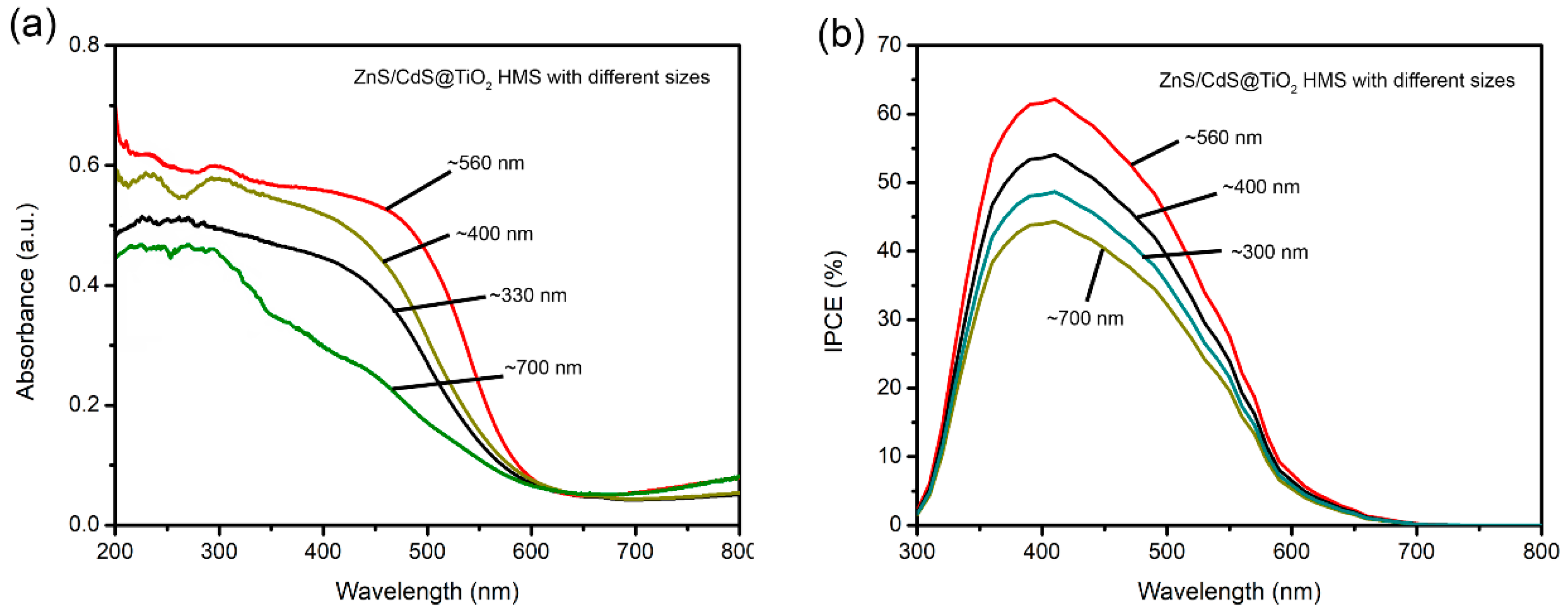
In order to testify our claims, the UV-vis spectra of ZnS/CdS@TiO2 HMS with different sizes are recorded in Figure 7a. Two obvious phenomena are observed, one is that the onset of light absorption ~550 nm for all ZnS/CdS@TiO2 HMS photoanodes, indicating that the light absorption depend on ZnS/CdS QDs rather than TiO2 HMS. However, the absorbance of photoanodes seems to be influenced by sizes of TiO2 HMS, because the ZnS/CdS@TiO2 HMS with ~560 nm shows the higher absorbance than any other sizes of TiO2 HMS. As UV-Vis spectra indicated, the light absorption range of ZnS/CdS QDs is mainly below 550 nm, which means a strong light scattering may occur when the size of TiO2 supporting architecture is comparable with it. In our case, the ~560 nm TiO2 HMS is just in agreement with this wavelength to yield stronger light scattering and result in the enhancement of light harvesting efficiency, leading to the enhancement of absorbance. The incidental photon to current conversion efficiency (IPCE) of ZnS/CdS@TiO2 HMS with different sizes are monitored to further decipher the size effect of TiO2 HMS on photovoltaic performance, which are shown in Figure 7b. It can be found that the IPCE value depend greatly on the size of TiO2 HMS. Especially, the highest IPCE is achieved by ZnS/CdS@TiO2 HMS with size ~560 nm. Three factors including light harvesting efficiency (LHE), electron injection efficiency (Φing), and charge collecting efficiency (ηcc) determine the IPCE value, as following equations [32]:
IPCE = LHEΦingηcc
LHE =1 − 10−absorbance
In our case, apart from light reflection at the shell of the hollow spherical structure, a stronger light scattering is caused by ~560 nm TiO2 HMS comparable to the wavelength of light absorbed by ZnS/CdS QDs, which enhances the light harvesting efficiency and contributes to the increase of IPCE. Furthermore, stronger light scattering lead to QDs absorbing more photons, and yield a higher absorbance to enhance the light harvesting efficiency, finally leading to high IPCE value and Jsc. These results confirmed that the superior light scattering properties depend on the size effect of TiO2 HMS, and changing the size in an appropriate range to agree with wavelength of absorbed light is beneficial to enhance the light harvesting efficiency.
As previous reports have mentioned [33,34], the PbS QDs can help to absorb more photons and increase the Jsc further. The ZnS/PbS/CdS QD was applied to our ~560 nm TiO2 HMS to further improve photovoltaic performance and explore if the supporting architecture is suitable in other types of QDSSC. Figure S4 (Supplementary Figure S4) shows the best I-V test result of ZnS/PbS/CdS QDSSC based on ~560 nm TiO2 HMS, presenting a PCE of 2.73% with a significant increment of Jsc to 13.50 mA cm−2. This result demonstrated that a high efficient QDSSC is predictable by tailoring suitable QDs system in TiO2 HMS.
5. Conclusions
In summary, size controllable TiO2 HMS have been successfully synthesized by the CS template method. Based on TiO2 HMS with sizes of ~330 nm, ~400 nm, ~560 nm, and ~700 nm, the ZnS/CdS QDs sensitized TiO2 HMS solar cells have been constructed. The size effect of TiO2 HMS on photovoltaic performance of QDSSC has been investigated in contrast. It was found that with the same ZnS/CdS QDs, the photovoltaic performance, especially the Jsc of sample solar cells, depend greatly on the size of TiO2 HMS. In comparison, when the size of TiO2 HMS (~560 nm) is comparable to the light wavelength that ZnS/CdS QDs (~550 nm) can absorb, the best Jsc of 8.02 mA cm−2 and the highest PCE of 1.83% among the sample solar cells have been achieved. The UV-vis and IPCE analysis confirmed that a stronger light scattering generated by TiO2 HMS with ~560 nm is responsible for the enhancement of light harvesting efficiency, leading to the increment of Jsc and PCE. The further application of ~560 nm TiO2 HMS in ZnS/PbS/CdS QDSSC can improve the PCE to 2.73%, demonstrating the wide applicability of TiO2 HMS in QDSSCs. These findings may offer potential insights with respect to the design of TiO2 architectures for improving the photovoltaic performance of QDSSCs.
Supplementary Materials
The following are available online at https://www.mdpi.com/1996-1944/12/10/1583/s1, Figure S1: The IR spectrum of carbonaceous spheres template, Figure S2: The XRD pattern of TiO2 hollow microspheres obtained by carbonaceous template method, Figure S3: The N2 adsorption-desorption isotherm curves of TiO2 HMS with different sizes, (a) ~330 nm, (b) ~700 nm, Figure S4: The J-V curves of QDSSC based on TiO2 HMS with different sizes, (a) ~330 nm TiO2 HMS, (b) ~400 nm TiO2 HMS, (c) ~560 nm TiO2 HMS, (d) ~700 nm TiO2 HMS; three times repeated tests were carried out on each QDSSC, and the best results are showed, Figure S5: The J-V curve of ZnS/PbS/CdS QDSSC based on ~560 nm TiO2 HMS.
Author Contributions
Methodology, Validation, Investigation, Writing—Original Draft Preparation, Conceptualization, and Writing—Review & Editing, Z.L.; Resources, Supervision, Project Administration, L.Y.
Funding
This research was funded by the National Natural Science Foundation of China (grant number 51862007), and the Natural Science Foundation of Gansu Province, China (grant number 18JR3RG210).
Acknowledgments
We greatly thank Lei Feng who is from College of Chemistry and Chemical Engineering, Hexi University for his support of Muffle Furnace use in our experiments.
Conflicts of Interest
The authors declare no conflict of interest.
References
- Lai, X.; Halpert, J.E.; Wang, D. Recent advances in micro-/nano-structured hollow spheres for energy applications: From simple to complex systems. Energy Environ. Sci. 2012, 5, 5604–5618. [Google Scholar] [CrossRef]
- Liu, H.; Ma, H.; Joo, J.; Yin, Y. Contribution of multiple reflections to light utilization efficiency of submicron hollow TiO2 photocatalyst. Sci. China Mater. 2016, 59, 1017–1026. [Google Scholar] [CrossRef]
- Guo, K.; Li, M.; Fang, X.; Bai, L.; Luoshan, M.; Zhang, F.; Zhao, X. Improved properties of dye-sensitized solar cells by multifunctional scattering layer of yolk-shell-like TiO2 microspheres. J. Power Sources 2014, 264, 35–41. [Google Scholar] [CrossRef]
- Dong, Z.; Lai, X.; Halpert, J.E.; Yang, N.; Yi, L.; Zhai, J.; Wang, D.; Tang, Z.; Jiang, L. Accurate control of multishelled ZnO hollow microspheres for dye-sensitized solar cells with high efficiency. Adv. Mater. 2012, 24, 1046–1049. [Google Scholar] [CrossRef]
- Zhang, J.; Wang, S.; Wang, Y.; Xu, M.; Xia, H.; Zhang, S.; Huang, W.; Guo, X.; Wu, S. ZnO hollow spheres: Preparation, characterization, and gas sensing properties. Sens. Actuators B-Chem. 2009, 139, 411–417. [Google Scholar] [CrossRef]
- Cai, Y.; Wang, H.E.; Zhao, X.; Huang, F.; Wang, C.; Deng, Z.; Li, Y.; Cao, G.; Su, B.L. Walnut-like porous core/shell TiO2 with hybridized phases enabling fast and stable lithium storage. ACS Appl. Mater. Interfaces 2017, 9, 10652–10663. [Google Scholar] [CrossRef]
- Caruso, F.; Shi, X.; Caruso, R.A.; Susha, A. Hollow titania spheres from layered precursor deposition on sacrificial colloidal core particles. Adv. Mater. 2001, 13, 740–744. [Google Scholar] [CrossRef]
- Hu, H.; Shen, H.; Cui, C.; Liang, D.; Li, P.; Xu, S.; Tang, W. Preparation and photoelectrochemical properties of TiO2 hollow spheres embedded TiO2/CdS photoanodes for quantum-dot-sensitized solar cells. J. Alloys Compd. 2013, 560, 1–5. [Google Scholar] [CrossRef]
- Shao, F.; Sun, J.; Gao, L.; Yang, S.; Luo, J. Template-free synthesis of hierarchical TiO2 structures and their application in dye-sensitized solar cells. ACS Appl. Mater. Interfaces 2011, 3, 2148–2153. [Google Scholar] [CrossRef] [PubMed]
- Song, X.; Wang, M.; Deng, J.; Yang, Z.; Ran, C.; Zhang, X.; Yao, X. One-step preparation and assembly of aqueous colloidal CdSxSe1−x nanocrystals within mesoporous TiO2 films for quantum dot-sensitized solar cells. ACS Appl. Mater. Interfaces 2013, 5, 5139–5148. [Google Scholar] [CrossRef]
- Baker, D.R.; Kamat, P.V. Photosensitization of TiO2 nanostructures with CdS quantum dots: Particulate versus tubular support architectures. Adv. Funct. Mater. 2009, 19, 805–811. [Google Scholar] [CrossRef]
- Du, J.; Du, Z.; Hu, J.S.; Pan, Z.; Shen, Q.; Sun, J.; Long, D.; Dong, H.; Sun, L.; Zhong, X. Zn-Cu-In-Se quantum dot solar cells with a certified power conversion efficiency of 11.6%. J. Am. Chem. Soc. 2016, 138, 4201–4209. [Google Scholar] [CrossRef]
- Ren, H.; Yu, R.; Wang, J.; Jin, Q.; Yang, M.; Mao, D.; Kisailus, D.; Zhao, H.; Wang, D. Multishelled TiO2 hollow microspheres as anodes with superior reversible capacity for lithium ion batteries. Nano Lett. 2014, 14, 6679–6684. [Google Scholar] [CrossRef]
- Fabregat-Santiago, F.; Barea, E.M.; Bisquert, J.; Mor, G.K.; Shankar, K.; Grimes, C.A. High carrier density and capacitance in TiO2 nanotube arrays induced by electrochemical doping. J. Am. Chem. Soc. 2008, 130, 11312–11316. [Google Scholar] [CrossRef]
- Yu, L.; Ren, X.; Yang, Z.; Han, Y.; Li, Z. The preparation and assembly of CdSxSe1−x alloyed quantum dots on TiO2 nanowire arrays for quantum dot-sensitized solar cells. J. Mater. Sci. Mater. Electron. 2016, 27, 7150–7160. [Google Scholar] [CrossRef]
- Zhou, R.; Zhang, Q.; Uchaker, E.; Lan, J.; Yin, M.; Cao, G. Mesoporous TiO2 beads for high efficiency CdS/CdSe quantum dot co-sensitized solar cells. J. Mater. Chem. A 2014, 2, 2517. [Google Scholar] [CrossRef]
- Nie, Z.; Wang, Y.; Zhang, Y.; Pan, A. Multi-shelled α-Fe2O3 microspheres for high-rate supercapacitors. Sci. China Mater. 2016, 59, 247–253. [Google Scholar] [CrossRef]
- Du, H.; Jiao, L.; Wang, Q.; Yang, J.; Guo, L.; Si, Y.; Wang, Y.; Yuan, H. Facile carbonaceous microsphere templated synthesis of Co3O4 hollow spheres and their electrochemical performance in supercapacitors. Nano Res. 2012, 6, 87–98. [Google Scholar] [CrossRef]
- Wang, X.; Hu, P.; Yuan, F.; Yu, L. Preparation and characterization of ZnO hollow spheres and ZnO-carbon composite materials using colloidal carbon spheres as templates. J. Phys. Chem. C 2007, 111, 6706–6712. [Google Scholar] [CrossRef]
- Titirici, M.-M.; Antonietti, M.; Thomas, A. A generalized synthesis of metal oxide hollow spheres using a hydrothermal approach. Chem. Mater. 2006, 18, 3808–3812. [Google Scholar] [CrossRef]
- Liu, Y.; Lan, K.; Bagabas, A.A.; Zhang, P.; Gao, W.; Wang, J.; Sun, Z.; Fan, J.; Elzatahry, A.A.; Zhao, D. Ordered macro/mesoporous TiO2 hollow microspheres with highly crystalline thin shells for high-efficiency photoconversion. Small 2016, 12, 860–867. [Google Scholar] [CrossRef] [PubMed]
- Du, J.; Qi, J.; Wang, D.; Tang, Z. Facile synthesis of Au@TiO2 core-shell hollow spheres for dye-sensitized solar cells with remarkably improved efficiency. Energy Environ. Sci. 2012, 5, 6914–6918. [Google Scholar] [CrossRef]
- Zhang, Q.; Chou, T.P.; Russo, B.; Jenekhe, S.A.; Cao, G. Polydisperse aggregates of ZnO nanocrystallites: A method for energy-conversion-efficiency enhancement in dye-sensitized solar cells. Adv. Funct. Mater. 2008, 18, 1654–1660. [Google Scholar] [CrossRef]
- Xi, J.; Zhang, Q.; Park, K.; Sun, Y.; Cao, G. Enhanced power conversion efficiency in dye-sensitized solar cells with TiO2 aggregates/nanocrystallites mixed photoelectrodes. Electrochim. Acta 2011, 56, 1960–1966. [Google Scholar] [CrossRef]
- Huang, F.; Chen, D.; Zhang, X.L.; Caruso, R.A.; Cheng, Y.-B. Dual-function scattering layer of submicrometer-sized mesoporous TiO2 beads for high-efficiency dye-sensitized solar cells. Adv. Funct. Mater. 2010, 20, 1301–1305. [Google Scholar] [CrossRef]
- Zhang, B.; Zheng, J.; Li, X.; Fang, Y.; Wang, L.W.; Lin, Y.; Pan, F. Tuning band alignment by CdS layers using a SILAR method to enhance TiO2/CdS/CdSe quantum-dot solar-cell performance. Chem Commun. 2016, 52, 5706–5709. [Google Scholar] [CrossRef] [PubMed]
- Li, Z.; Yu, L.; Liu, Y.; Sun, S. CdS/CdSe quantum dots co-sensitized TiO2 nanowire/nanotube solar cells with enhanced efficiency. Electrochim. Acta 2014, 129, 379–388. [Google Scholar] [CrossRef]
- Cheng, S.; Fu, W.; Yang, H.; Zhang, L.; Ma, J.; Zhao, H.; Sun, M.; Yang, L. Photoelectrochemical performance of multiple semiconductors (CdS/CdSe/ZnS) cosensitized TiO2 photoelectrodes. J. Phys. Chem. C 2012, 116, 2615–2621. [Google Scholar] [CrossRef]
- Liu, Y.; Li, Z.; Yu, L.; Sun, S. Effect of the nature of cationic precursors for SILAR deposition on the performance of CdS and PbS/CdS quantum dot-sensitized solar cells. J. Nanopart. Res. 2015, 17, 132. [Google Scholar] [CrossRef]
- Li, Z.; Lai, X.; Wang, H.; Mao, D.; Xing, C.; Wang, D. General synthesis of homogeneous hollow core-shell ferrite microspheres. J. Phys. Chem. C 2009, 113, 2792–2797. [Google Scholar] [CrossRef]
- Yu, L.; Li, Z. Synthesis of ZnxCd1−xSe@ZnO hollow spheres in different sizes for quantum dots sensitized solar cells application. Nanomaterials 2019, 9, 132. [Google Scholar] [CrossRef]
- Choi, Y.; Seol, M.; Kim, W.; Yong, K. Chemical bath deposition of stoichiometric CdSe quantum dots for efficient quantum-dot-sensitized solar cell application. J. Phys. Chem. C 2014, 118, 5664–5670. [Google Scholar] [CrossRef]
- Kholmicheva, N.; Moroz, P.; Rijal, U.; Bastola, E.; Uprety, P.; Liyanage, G.; Razgoniaev, A.; Ostrowski, A.D.; Zamkov, M. Plasmonic nanocrystal solar cells utilizing strongly confined radiation. ACS Nano 2014, 8, 12549–12559. [Google Scholar] [CrossRef]
- Moroz, P.; Liyanage, G.; Kholmicheva, N.N.; Yakunin, S.; Rijal, U.; Uprety, P.; Bastola, E.; Mellott, B.; Subedi, K.; Sun, L. Infrared emitting PbS nanocrystal solids through matrix encapsulation. Chem. Mater. 2014, 26, 4256–4264. [Google Scholar] [CrossRef]
Figure 1.
(a–d) SEM images of carbonaceous spheres (CS) with different sizes synthesized by tuning concentration of sucrose; (e–h) SEM images of TiO2 hollow microspheres (HMS) fabricated by different sizes of CS templates.
Figure 1.
(a–d) SEM images of carbonaceous spheres (CS) with different sizes synthesized by tuning concentration of sucrose; (e–h) SEM images of TiO2 hollow microspheres (HMS) fabricated by different sizes of CS templates.

Figure 2.
(a) TEM image of CS template; (b) TEM image of TiO2 HMS in low magnification; (c) magnified TEM image of TiO2 HMS; (d) EDS of TiO2 HMS; (e) SEM elemental mapping scan results of a single TiO2 HMS.
Figure 2.
(a) TEM image of CS template; (b) TEM image of TiO2 HMS in low magnification; (c) magnified TEM image of TiO2 HMS; (d) EDS of TiO2 HMS; (e) SEM elemental mapping scan results of a single TiO2 HMS.

Figure 3.
(a) The formation illustration of TiO2 HMS by CS template method; (b) the mechanism of size controllable synthesis of TiO2 HMS by CS template method.
Figure 3.
(a) The formation illustration of TiO2 HMS by CS template method; (b) the mechanism of size controllable synthesis of TiO2 HMS by CS template method.

Figure 4.
(a) TEM of ZnS/CdS@TiO2 HMS, the inset is magnified TEM of single ZnS/CdS@TiO2 HMS; (b) EDS of ZnS/CdS@TiO2 HMS from the selected spot; (c) SEM of ZnS/CdS@TiO2 HMS; (d) surface SEM elemental mapping of ZnS/CdS@TiO2 HMS.
Figure 4.
(a) TEM of ZnS/CdS@TiO2 HMS, the inset is magnified TEM of single ZnS/CdS@TiO2 HMS; (b) EDS of ZnS/CdS@TiO2 HMS from the selected spot; (c) SEM of ZnS/CdS@TiO2 HMS; (d) surface SEM elemental mapping of ZnS/CdS@TiO2 HMS.

Figure 5.
Current density-voltage (J-V) curves of QDSSCs based on ZnS/CdS@TiO2 HMS with size ~330 nm, ~400 nm, ~560 nm, and ~700 nm, respectively.
Figure 5.
Current density-voltage (J-V) curves of QDSSCs based on ZnS/CdS@TiO2 HMS with size ~330 nm, ~400 nm, ~560 nm, and ~700 nm, respectively.

Figure 6.
(a) The working model of ZnS/CdS@TiO2 HMS QDSSC; (b) the charges transport mechanism in ZnS/CdS@TiO2 HMS QDSSC.
Figure 6.
(a) The working model of ZnS/CdS@TiO2 HMS QDSSC; (b) the charges transport mechanism in ZnS/CdS@TiO2 HMS QDSSC.

Figure 7.
(a) UV-vis spectra of ZnS/CdS@TiO2 HMS with different sizes; (b) IPCE of ZnS/CdS@TiO2 HMS with different sizes.
Figure 7.
(a) UV-vis spectra of ZnS/CdS@TiO2 HMS with different sizes; (b) IPCE of ZnS/CdS@TiO2 HMS with different sizes.


Table 1.
Size effect of TiO2 HMS on photovoltaic performance of ZnS/CdS QDSSC.
| Size (nm) | Voc (V) | Jsc (mA cm−2) | FF | PCE (%) |
|---|---|---|---|---|
| 330 | 0.47 | 6.23 | 0.46 | 1.34 |
| 400 | 0.46 | 6.86 | 0.47 | 1.48 |
| 560 | 0.49 | 8.02 | 0.47 | 1.83 |
| 700 | 0.46 | 5.44 | 0.46 | 1.18 |
© 2019 by the authors. Licensee MDPI, Basel, Switzerland. This article is an open access article distributed under the terms and conditions of the Creative Commons Attribution (CC BY) license (http://creativecommons.org/licenses/by/4.0/).
Share and Cite
MDPI and ACS Style
Li, Z.; Yu, L. The Size Effect of TiO2 Hollow Microspheres on Photovoltaic Performance of ZnS/CdS Quantum Dots Sensitized Solar Cell. Materials 2019, 12, 1583. https://doi.org/10.3390/ma12101583
AMA Style
Li Z, Yu L. The Size Effect of TiO2 Hollow Microspheres on Photovoltaic Performance of ZnS/CdS Quantum Dots Sensitized Solar Cell. Materials. 2019; 12(10):1583. https://doi.org/10.3390/ma12101583
Chicago/Turabian StyleLi, Zhen, and Libo Yu. 2019. "The Size Effect of TiO2 Hollow Microspheres on Photovoltaic Performance of ZnS/CdS Quantum Dots Sensitized Solar Cell" Materials 12, no. 10: 1583. https://doi.org/10.3390/ma12101583
Note that from the first issue of 2016, this journal uses article numbers instead of page numbers. See further details here.