3.1. Effect on Microstructure
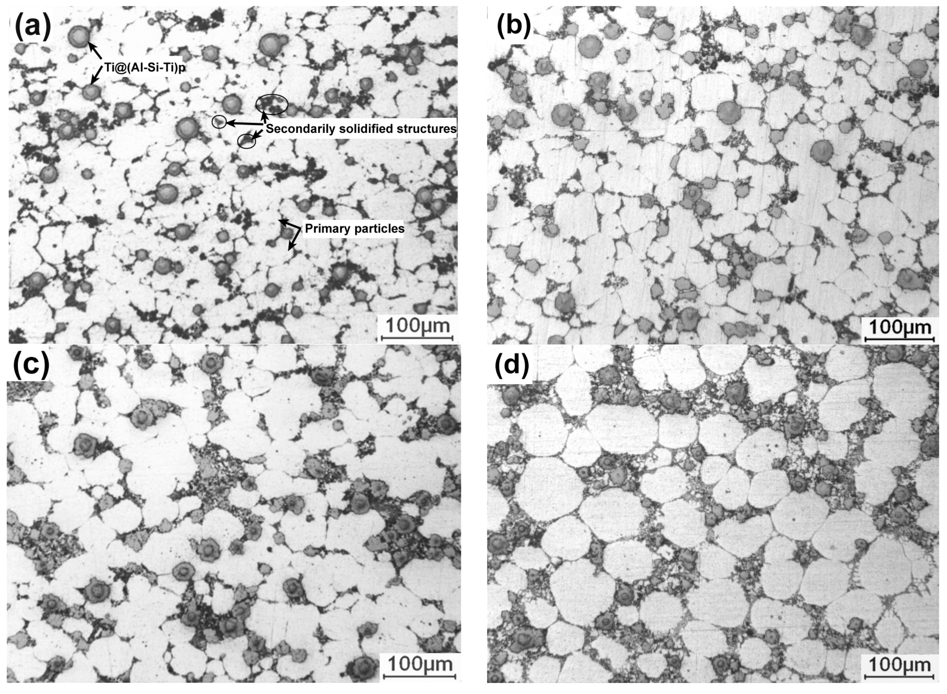
Figure 1 shows the microstructures of the Ti@(Al-Si-Ti)
p/A356 matrix composites thixoformed at reheating for 50 min at different temperatures. It can be seen that all of the microstructures are composed of primary particles, 3Ss and Ti@(Al-Si-Ti)
p. The Ti@(Al-Si-Ti)
p distribute in the regions between the primary particles, i.e., in the 3Ss, and their distribution is quite uniform at the reheating temperatures of 590 °C and 600 °C (
Figure 1a,b). But they tend to agglomerate as the temperature rises (
Figure 1c,d). The primary particles at 590 °C are in a form of interconnected small particles (
Figure 1a), and are separated by the 3Ss accompanied with their growth, evolving into the individual spheroidal particles with an average size of about 55 μm at 600 °C (
Figure 1b). But they then tend to agglomerate to form large-sized interconnected irregular particles when the temperature is further elevated (
Figure 1c), and finally become large spheroidal particles at 610 °C (
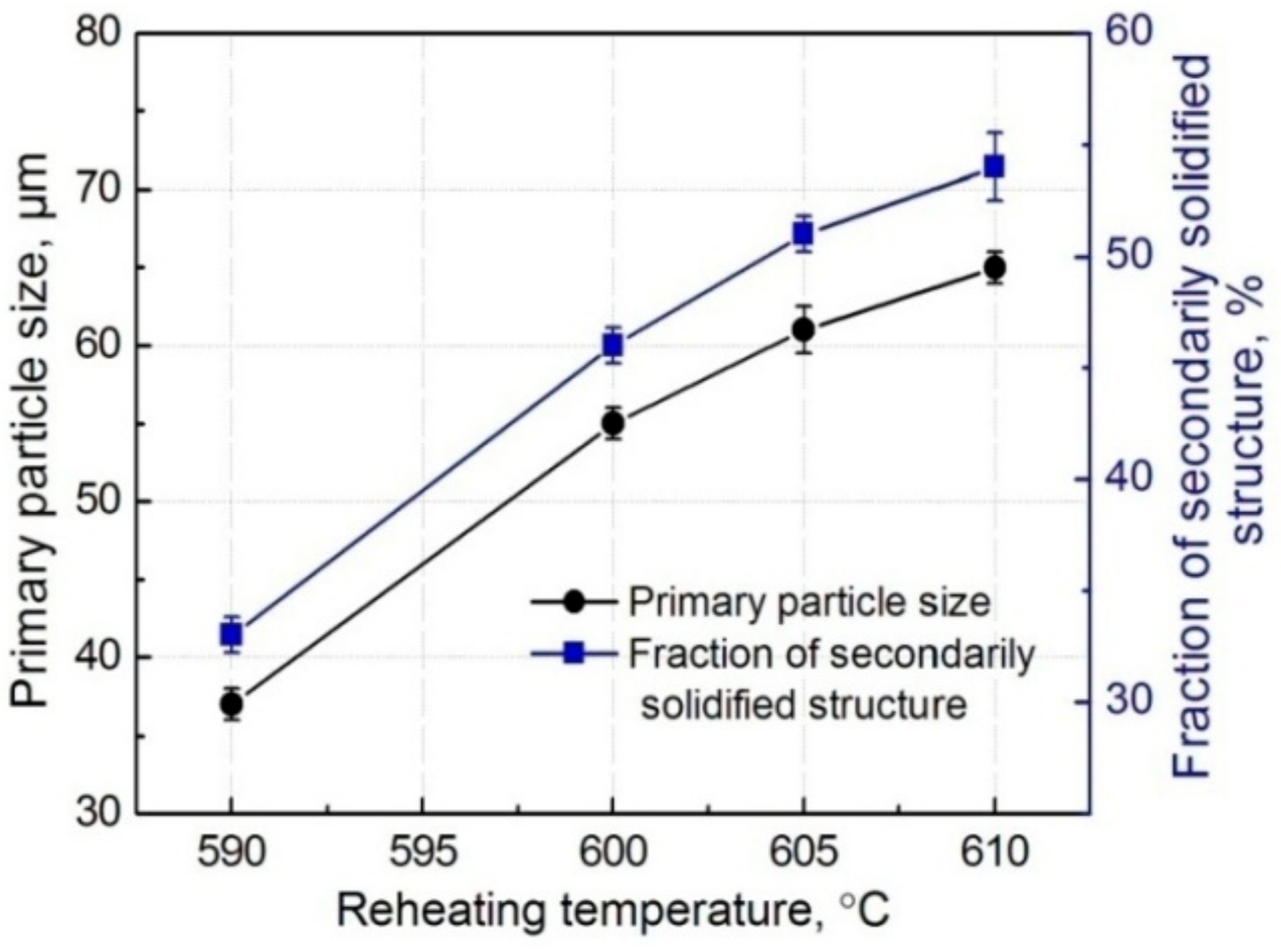
Figure 1d). In general, the primary particles show a continuous growth trend with rising the temperatures. In addition, the 3Ss amount also steadily increases all the while (comparing the images in
Figure 1). As shown by
Figure 2, the quantitative examinations more clearly indicate that both the primary particle size and 3Ss fraction all continuously increase as the reheating temperature rises. In general, the composite thixoformed at 600 °C has a typical semisolid forming microstructure with middle-sized primary particles and uniformly-distributed reinforcing particles.
It is known that reheating temperature mainly determines the liquid fraction of a semisolid ingot. The higher the temperature is, the more the liquid phase is, and thus, the larger the amount of 3Ss that solidifies from the liquid phase is. At the temperature of 590 °C, the lowest temperature used in this work, the primary particles cannot be completely separated by liquid phase because there is not enough liquid phase, resulting in the interconnected small-particle structures (
Figure 1a). As the temperature rises, the primary particles are gradually separated by the increased liquid phase, i.e., the primary particles are separated by the 3Ss (
Figure 1b). During partial remelting, the size decrease of primary particles from their partial melting and the size increase from mergence and/or Ostwald ripening are in a dynamic competition status [
13,
14]. The present results indicate that the former factor is smaller than the latter one, and thus, the primary particle size continuously increases. The mergence is determined by the coupled effect of solid fraction and temperature, high solid fraction promotes the mergence, but low temperature at this condition slows the mergence due to the low atom diffusion rate.
Figure 1c implies that the mergence is quite active at 605 °C, resulting in the formation of the large irregular primary particles. But when the temperature exceeds 605 °C, Ostwald ripening becomes the main coarsening mechanism in view of their individual and spheroidal morphology (
Figure 1d). In addition, the increase of liquid phase and the coarsening of primary particles must give rise to the micro-segregation of liquid or solid phase, and thus, results in the aggregation of reinforcing particles that distribute in the liquid phase.
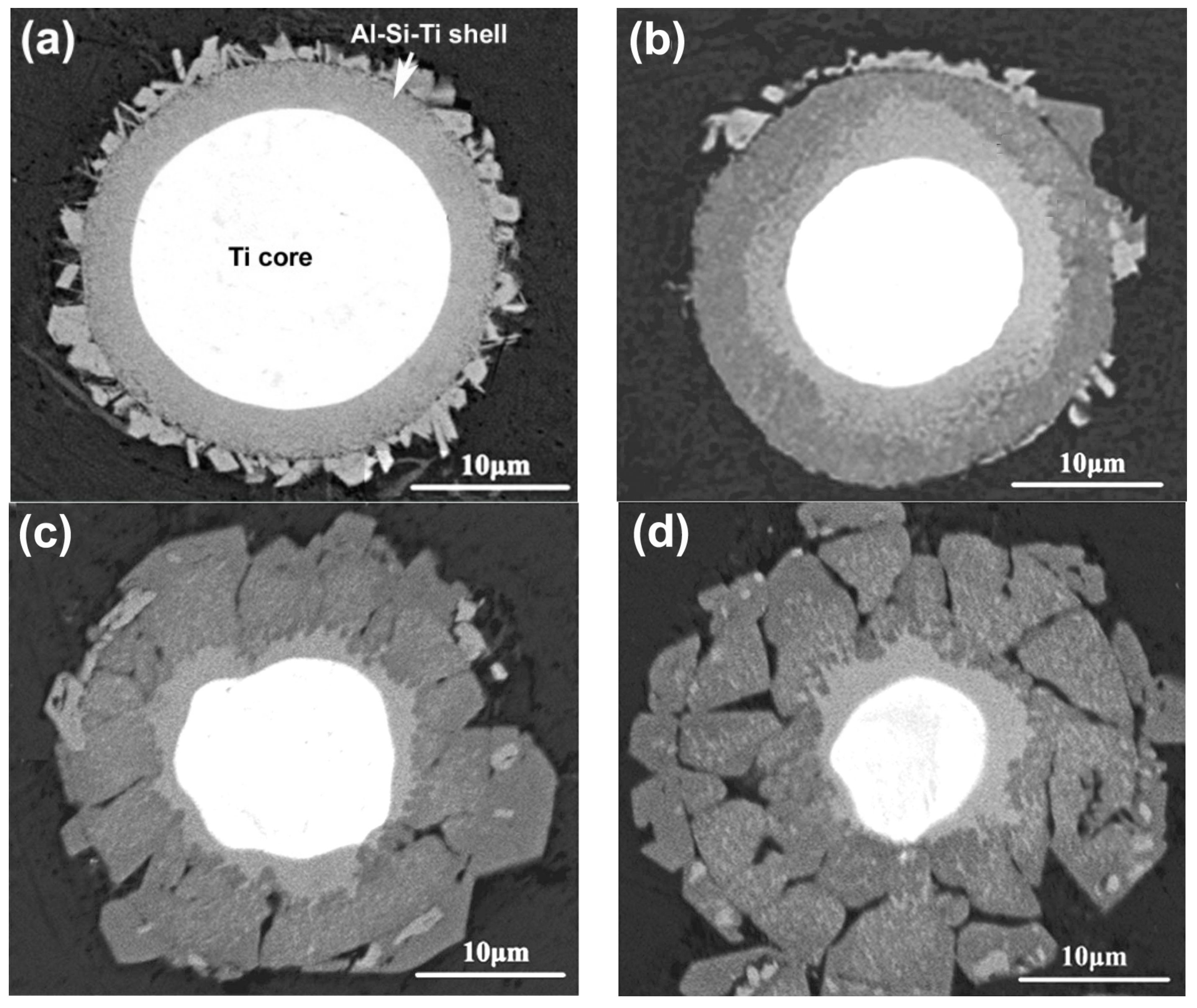
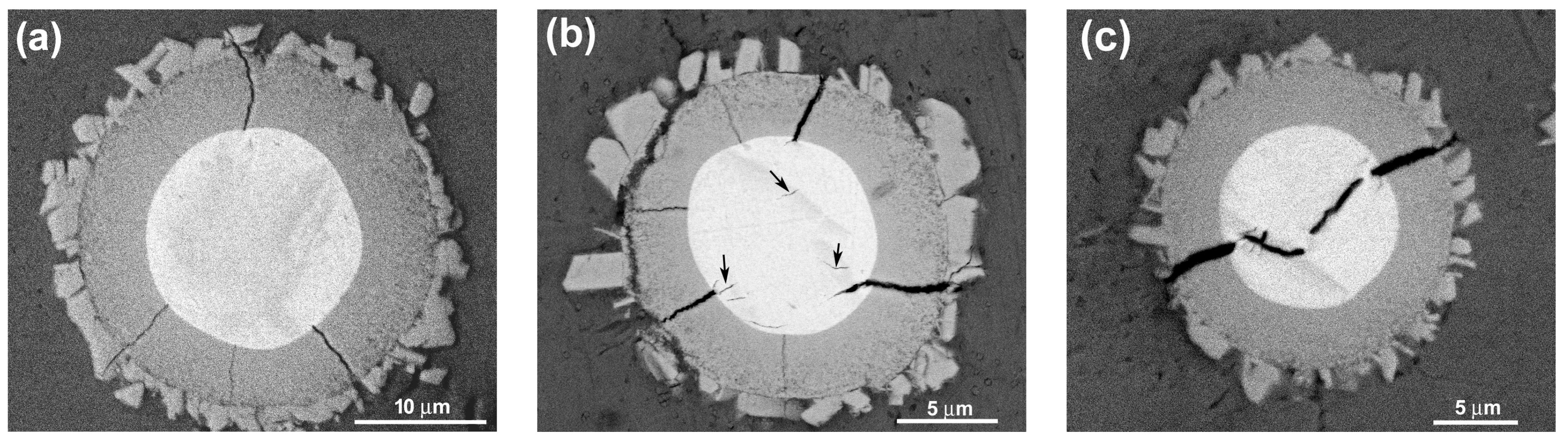
To verify the evolution process of the reinforcing particles with the reheating temperature, the specimens were also observed by SEM, as shown in
Figure 3. It is seen that the reinforcing particle at 590 °C presents a well core-shell-structure with a uniform and compact light grey shell in addition to a round of jagged structures (
Figure 2a). As the temperature rises, the reaction shell thickens and the outside jagged structures coarsen (
Figure 3b–d). Additionally, a kind of grey structure is formed from the outside of the light grey shell and the shell evolves into a dual-layer structure at 600 °C (
Figure 2b). Subsequently, some radial cracks generate within the thickened shell and the reinforcing particle becomes a structure that is composed of a small-sized core-shell-structured core (with a thin light grey shell) and surrounding cracked grey shell at 605 °C (
Figure 3c). Finally, the cracked grey structures peel off and the center part evolves into a smaller core-shell-structured particle, which is similar to the reinforcing particle at 605 °C, when the temperature rises to 610 °C (
Figure 3d). So it can be concluded that rising reheating temperature thickens the shells, but also promotes the shells to fracture. Reheating at 590–600 °C for 50 min can obtain perfect-morphology core-shell-structured reinforcing particles. In addition, elevating the temperature possibly facilitates the first formed compound shell to transform into another phase.
The white cores in
Figure 3 should be the residual Ti and the surrounding shells or other-morphological structures, including the outside jagged structures, are reaction compounds between the Ti powders and Al melt. The jagged structures originated from the reaction of TiO
2 film on the Ti powder surface with Al melt, and they belong to Al
2O
3-containing Al-Si-Ti compound [
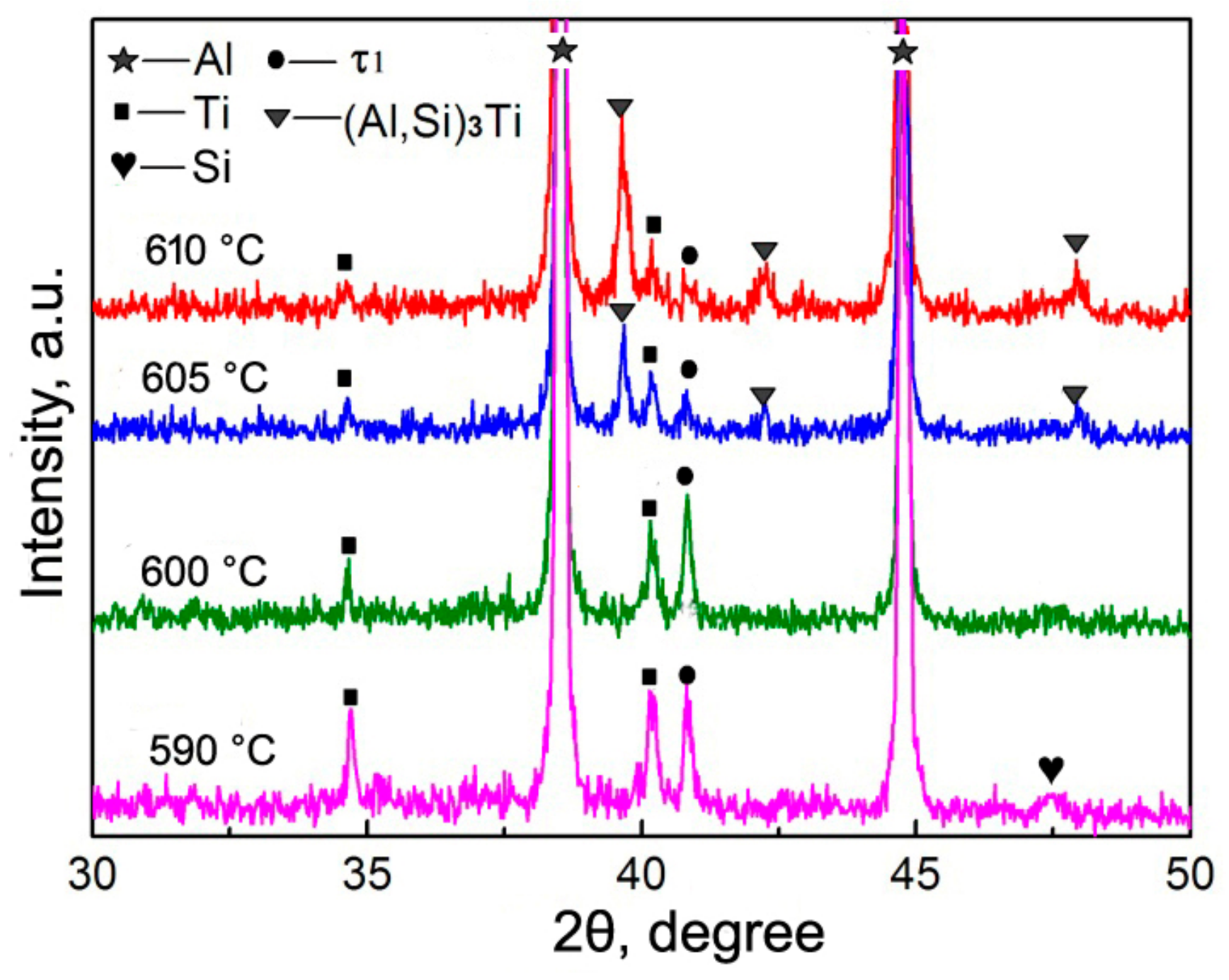
12]. The XRD results indicate that only one compound phase of τ1 (Al
5Si
12Ti
7) has formed at 590 °C, besides Al, Ti, and Si phases in the original powders (
Figure 4), which implies that the light grey shell in
Figure 3a is τ1 phase and the out jagged structures belong to Al
2O
3-containing τ1 phase. When the temperature rises, another Al-Si-Ti ternary phase of (Al,Si)
3Ti generates besides τ1 phase, and its diffraction intensities become more and more intensive, while those of τ1 phase get weaker and weaker (
Figure 4). It is found that the diffraction peaks of (Al,Si)
3Ti andτ1 phases are all not clear at 600 °C. This should be contributed to their relatively low concentrations. So it can be deduced that the light grey layers close to the Ti cores in
Figure 3b–d are τ1 phase and the out grey layers or cracked shells belong to (Al,Si)
3Ti phase. That is, the first formed τ1 phase gradually transforms into (Al,Si)
3Ti phase from the shell outside to inside as the reheating temperature rises.
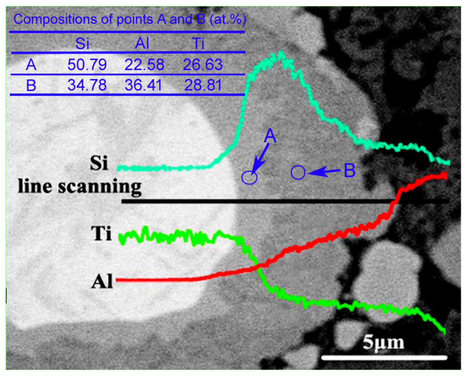
The EDS result of the reinforcing particles at 600 °C indicates that the inner light grey layer is rich in Si, while the out grey layer is rich in Al, and the Al concentration gradually increases towards the shell outside, while the variation of Si content is just opposite (
Figure 5). The quantitative examination shows that the Si concentration in the light grey layer (point A) is obviously higher than that in the grey layer (point B). This is consistent to the result that τ1 phase has higher Si content than (Al,Si)
3Ti phase [
24]. (Al,Si)
3Ti phase is formed from partial substitution of Al atoms in Al
3Ti phase by Si atoms and its composition varies in a wide range, but the crystal still maintains the tetragonal structure of Al
3Ti phase [
25]. In fact, the composition of τ1 phase also varies widely, although its accepted chemical formula is expressed as Al
5Si
12Ti
7 [
24]. When the Si content in (Al,Si)
3Ti phase exceeds 15.07%, it will transform into τ1 phase [
24,
25]. As discussed above, rising the reheating temperature not only generates more reaction product, and thus, consumes more Si element, but also generates more liquid phase from partial melting of primary Al particles. These two results must lead the concentration of Si in the Al melt to decrease, and then part of Si atoms in τ1 phase diffuses into Al melt, resulting in the transformation of τ1 phase with high Si content into (Al,Si)
3Ti phase with low Si content. This is demonstrated by the XRD results shown in
Figure 4, Si phase cannot be detected when the temperature exceeds 600 °C. In addition, this transformation should start from the interface of τ1 phase/Al melt and develop towards the shell inside. In view of thermodynamics, (Al,Si)
3Ti phase is more stable than τ1 phase at elevated temperatures [
26]. So rising the temperature facilitates τ1 phase to transform into (Al,Si)
3Ti phase. Furthermore, it can be seen that the newly formed product with Ti is always τ1 phase from
Figure 4 and
Figure 5, regardless of the reheating temperature. The reason is that the Si atom has a greater affinity with Ti than with Al [
24]. So we can conclude that the newly generated product of Ti with Al melt is always τ1 phase, but it will transform into (Al,Si)
3Ti phase due to the decreased Si content in Al melt and its increased thermodynamic instability with rising the reheating temperature.
It is known that volume expansion occurs during transformation of Ti into Al-Ti compounds [
27]. It is due to the reason that stress concentration generates in the shells and increases with the shell thickening. The shells thereby crack when the stress exceeds their strength and then peel off. Our previous investigation on the 2024Al-Ti system proposed that stress reached 15.89 GPa when a 2 μm Al
3Ti shell formed around a 9.28 μm Ti powder, which was higher than the theoretical strength of Al
3Ti phase (14.4 GPa) [
13]. In addition, the difference in volume expansion ratio was very large for forming different compounds, i.e., 2.55 for Al
3Ti, 1.8 for τ1 phases (according to the composition of Al
5Si
12Ti
7) and a value varied between 2.55 and 1.8 for (Al,Si)
3Ti with its composition [
14]. That is, the generated stress in (Al,Si)
3Ti phase is larger than that in τ1 phase. As discussed above, both the shell thickness and the proportion of (Al,Si)
3Ti phase increase as the reheating temperature rises. So the stress concentration increases by elevating the reheating temperature and the shells will crack as the temperature rises to a given value.
In summary, both the primary particle size and 3Ss amount in the composite increase by rising the reheating temperatures, accompanied by the agglomeration of reinforcing particles. Simultaneously, the reaction shells thicken, but fracture and peel off from the Ti cores when the temperature exceeds 600 °C. In addition, the firstly formed τ1-phase shells gradually transform into (Al,Si)3Ti phase from the outside to the inside. At 600 °C, a typical semisolid-forming microstructure with middle-sized primary particles and uniformly-distributed spheroidal core-shell-structured reinforcing particles with a thick, uniform, and compact dual-phase Al-Si-Ti compound shell are achieved.
3.2. Effects on Tensile Properties
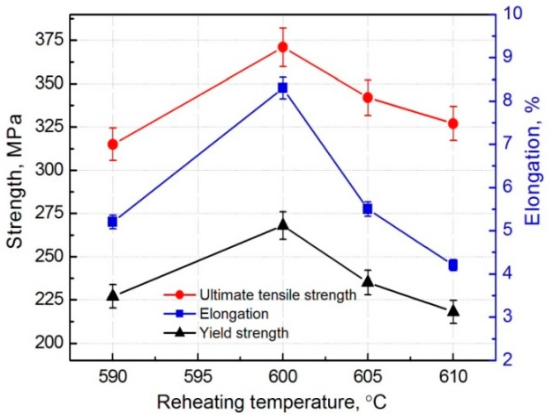
Figure 6 presents the variations of tensile properties of the composite with the reheating temperature. It shows that the ultimate tensile strength (UTS), yield strength (YS), and elongation all first increase as the temperature rises from 590 °C to 600 °C, and then continuously decrease. The UTS, YS, and elongation all reach the peak values of 371 MPa, 268 MPa, and 8.3% at 600 °C, respectively.
According to the microstructure characteristics discussed in the above section, the factors for affecting the tensile properties mainly include three aspects, the primary particle size, 3Ss amount and strengthening role of the reinforcing particles. First, the primary particle size continuously increases as the reheating temperature rises, which must decrease the tensile properties. Second, the 3Ss amount also increases with rising the temperature, which indirectly implies that the liquid fraction increases in the semisolid ingot prior to thixoforming. So the mould-filling ability and feeding capacity to solidification shrinkage during thixoforming, and thus, the microstructure compactness of the resulting composite is improved.
Table 1 gives the relative densities of the composites thixoformed at different reheating temperatures. It indicates that the density increases when the temperature rises from 590 °C to 600 °C. However, the feeding capacity is impaired due to the formation of the irregular large-sized interconnected primary particles as the temperature further rises (
Figure 1c), resulting in the decrease of the density (
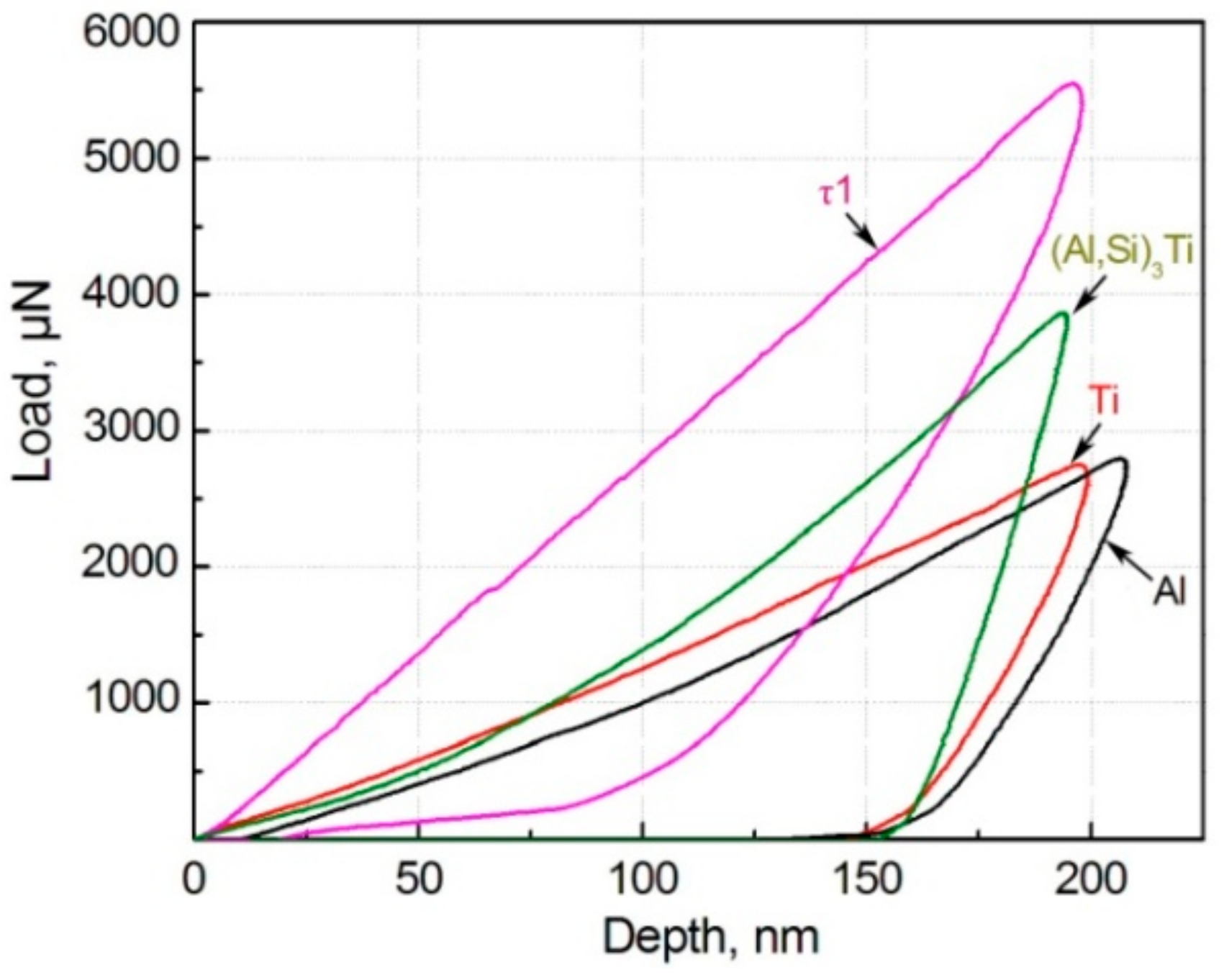
Table 1). In addition, the solidification behavior becomes closer to that of complete liquid melt due to more liquid formation. So the possibility for forming porosity is enhanced, also leading the density to decrease. Third, the total thickness of the shells increases and the first-formed τ1-phase shells gradually transforms into (Al,Si)
3Ti phase as the temperature rises. The (Al,Si)
3Ti phase is softer than the τ1 phase as shown by
Figure 7, but it is significantly harder than the Ti core and Al matrix.
Table 2 gives the values of the microhardness and elasticity modulus of the different phases in the composite. So the increase in shell thickness with raising the temperature from 590 °C to 600 °C must enhance the strengthening role of the reinforcing particles. But the strengthening effect is then impaired when the temperature exceeds 600 °C due to cracking of the shells (
Figure 3c). The present result indicates that the enhanced strengthening role from the increased shell thickness and improved microstructure compactness is larger than the weakening effect from the coarsened primary particles when the temperature rises from 590 °C to 600 °C. But all of the three factors have a negative effect on the strengthening role when the temperature exceeds 600 °C.
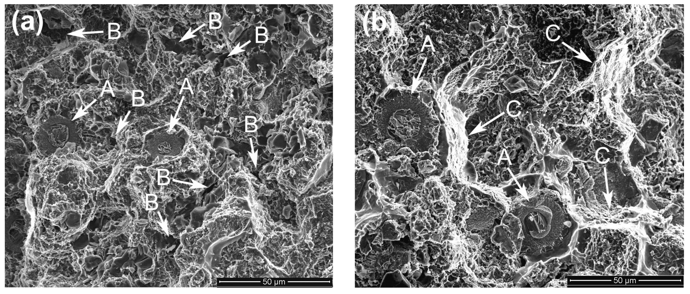
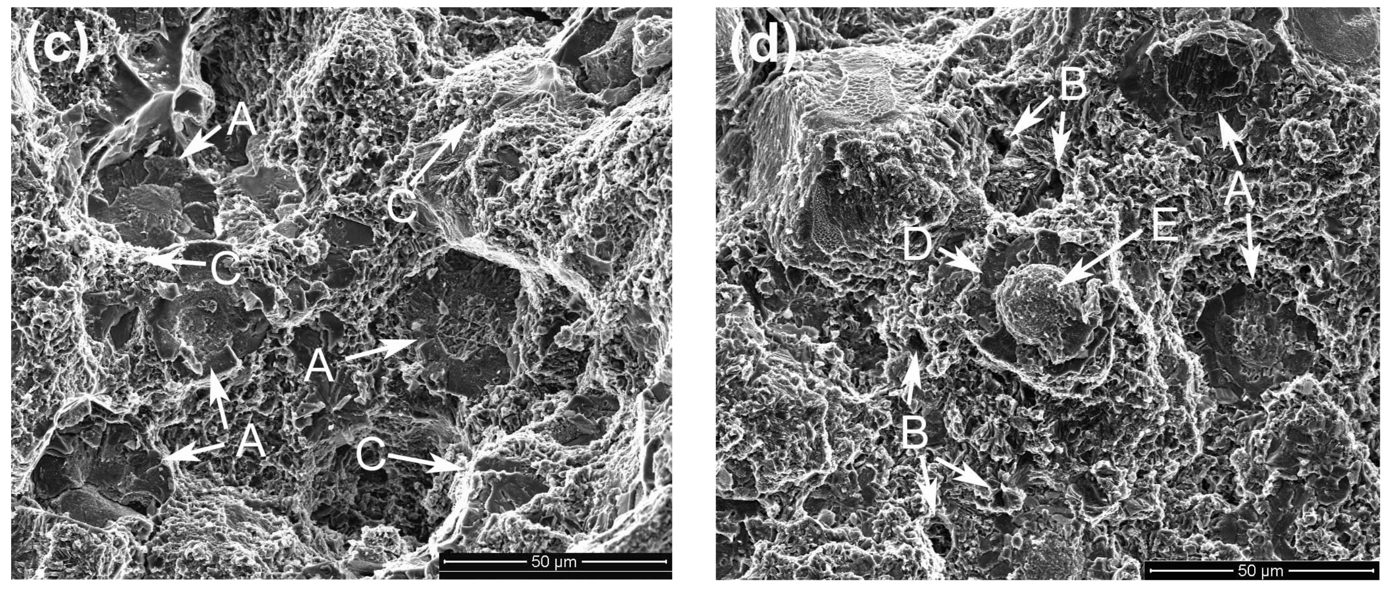
Figure 8 presents the typical fractographs of the composites. It shows that there is no obvious difference between them and they are all composed of torn matrix and fractured reinforcing particles (marked by arrows A). But three small differences are found through careful comparison. First, there are lots of small pores on the fracture surfaces of the composites thixoformed at 590 °C and 610 °C (marked by arrows B in
Figure 8a,d). This further demonstrates the variation of the microstructure compactness with the reheating temperature discussed above, and is consistent to the density variation (
Table 1). Second, the tearing trace of the matrix is more obvious for the composites thixoformed at 600 °C and 605 °C (marked by arrows C in
Figure 8b,c). This implies that these two composites should have high tensile properties, especially high elongation (
Figure 6). The reason should be mainly attributed to the improved matrix microstructure compactness. Third, the reinforcing particles for the composites formed at 590 °C–605 °C frequently fracture across their center region (marked by arrows A in
Figure 8a–c). But for the composite formed at 610 °C, some of them fracture in a dual-form, the surrounding shells fracture across themselves (marked by D in
Figure 8d), while the center cores debond from the shells (marked by E).
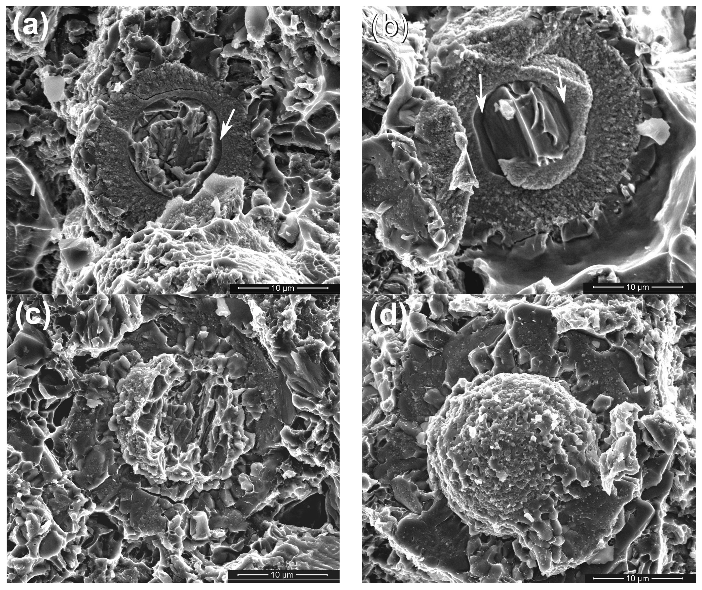
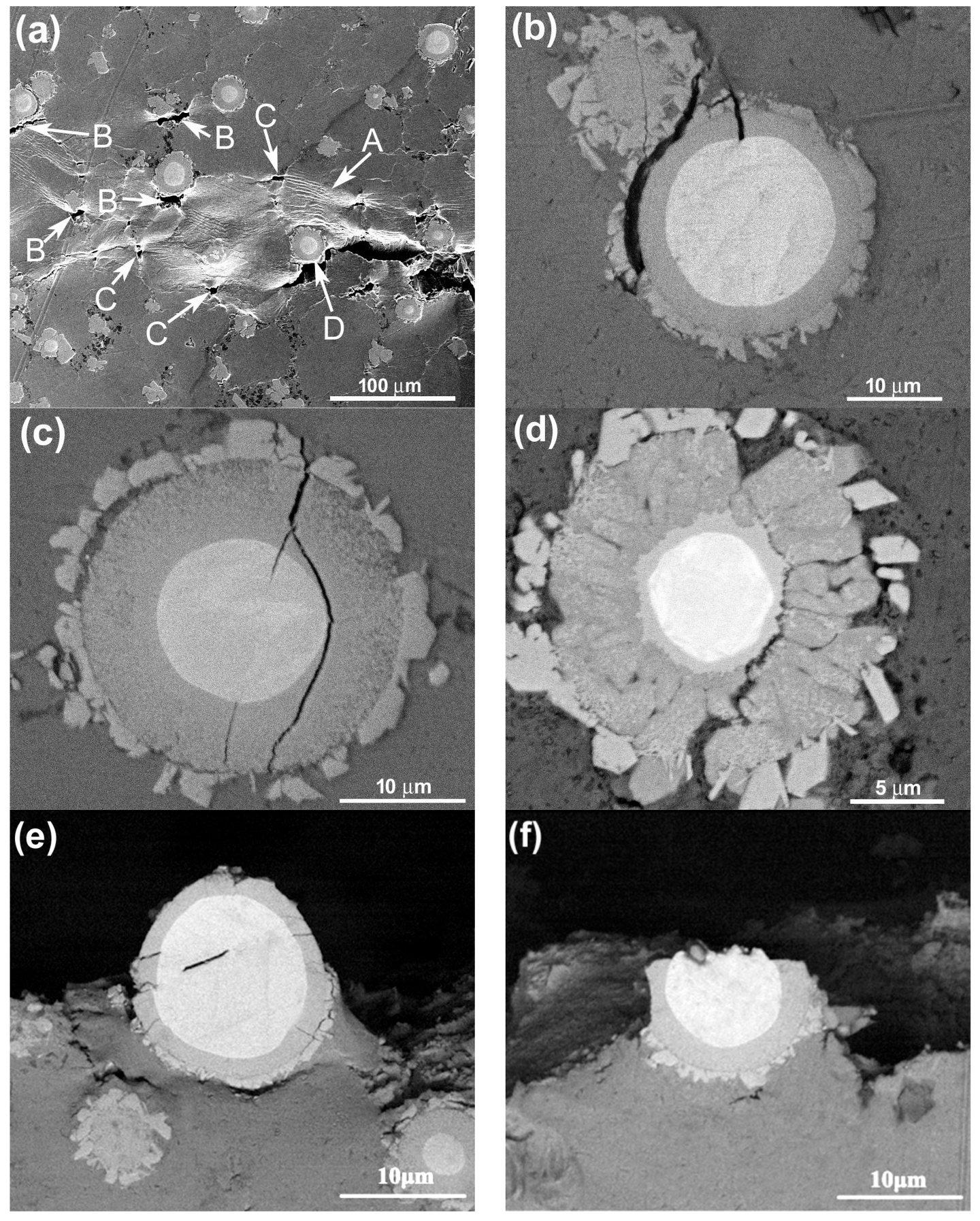
The typical morphologies of the visible reinforcing particles on fracture surfaces are more clearly shown in
Figure 9. It is obviously seen that the reinforcing particles for the composites thixoformed at 590 °C and 600 °C fracture through their center cores (
Figure 9a–c), while some of them for the composite at 610 °C only fracture across the outside shells and the cores debond from the shells to form a bulge (
Figure 9d).
Figure 9a and b also show that the shells at 590 °C and 600 °C are quite compact and the later one is obviously thicker than the former one. But the shells at 605 °C and 610 °C have cracks or have blocky characteristics (
Figure 9c,d). These microstructural features are completely consistent with the results from the metallographic observation in
Section 3.1. While the shells for the composite formed at 605 °C fracture, the bonding strength with the Ti cores, similar to those for the composites formed at 590 °C and 600 °C, should be quite strong, and thus, the reinforcements also frequently fracture across the center Ti cores. But the strengthening role of such reinforcements is smaller than that of the reinforcements with equivalent, even thinner, compact shells. As shown by
Figure 3d, the reinforcement at 610 °C is composed of a core-shell-structured particle core and surrounding compound particles. The bonding strength between these two parts should be relatively low, and thus, debonding is easy to occur and their strengthening role should be smaller than that of the ones with crack-containing shells. In addition, obvious gaps or cracks can be seen between the Ti core and compound shell for the composites formed at 590 °C and 600 °C (marked by arrows in
Figure 9a,b). This implies that the interface bonding between them is not so strong that partial debonding can occur during tensile testing. But the complete debonding, like that shown by
Figure 9d, is not found. All of these further demonstrate that the strengthening role of the reinforcements increases as the temperature rises, but decreases when the temperature exceeds 600 °C.
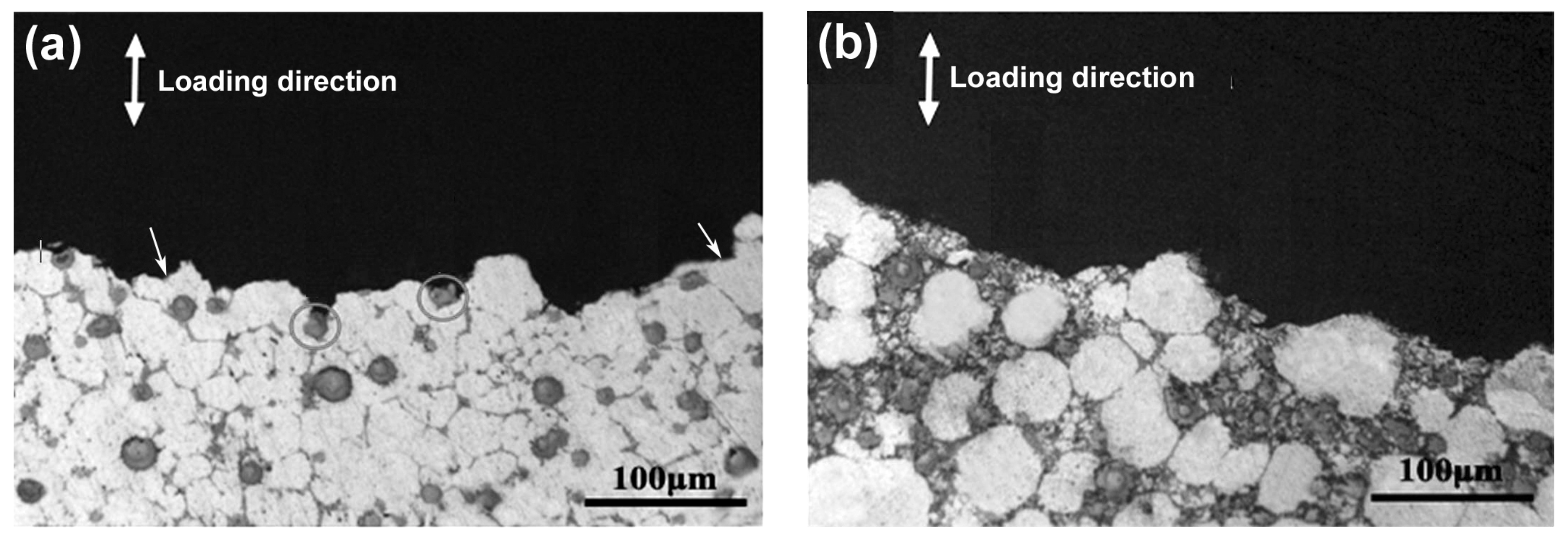
The observation for the side-views of the fracture surfaces indicates the crack propagation paths of all the composites during tensile testing are basically along the 3Ss between the primary particles, as shown by
Figure 10. The only difference is that cracks occasionally propagate across some primary particles for the composites thixoformed at 590 °C (marked by arrows in
Figure 10a). But this case becomes less and less as the temperature rises, and cracks almost completely propagate along the 3Ss when the temperature reaches 610 °C (
Figure 10b). As discussed above, pores such as shrinkage porosities and gas pores all distribute in the 3Ss. So the 3Ss are the weak points of the composites, and thus, cracks preferentially propagate along these structures. In addition, the primary particles at 590 °C are basically connected to each other (
Figure 1a) and they are gradually separated by the 3Ss, and finally evolve into the individual large-sized spheroidal particles at 610 °C (
Figure 1d). So it can be expected that cracks can occasionally propagate across some interconnected primary particles for the composites formed at low reheating temperatures, and this situation will decrease due to the separation of the primary particles by 3Ss and completely disappear as the temperature rises to a given degree.
From
Section 3.1 we know that all of the reinforcing particles distribute in the 3Ss for all of the four composites, so it is expected that some reinforcements will fracture when cracks encounter them during propagation, resulting in the visible cracked reinforcements on the fracture surfaces (
Figure 8 and
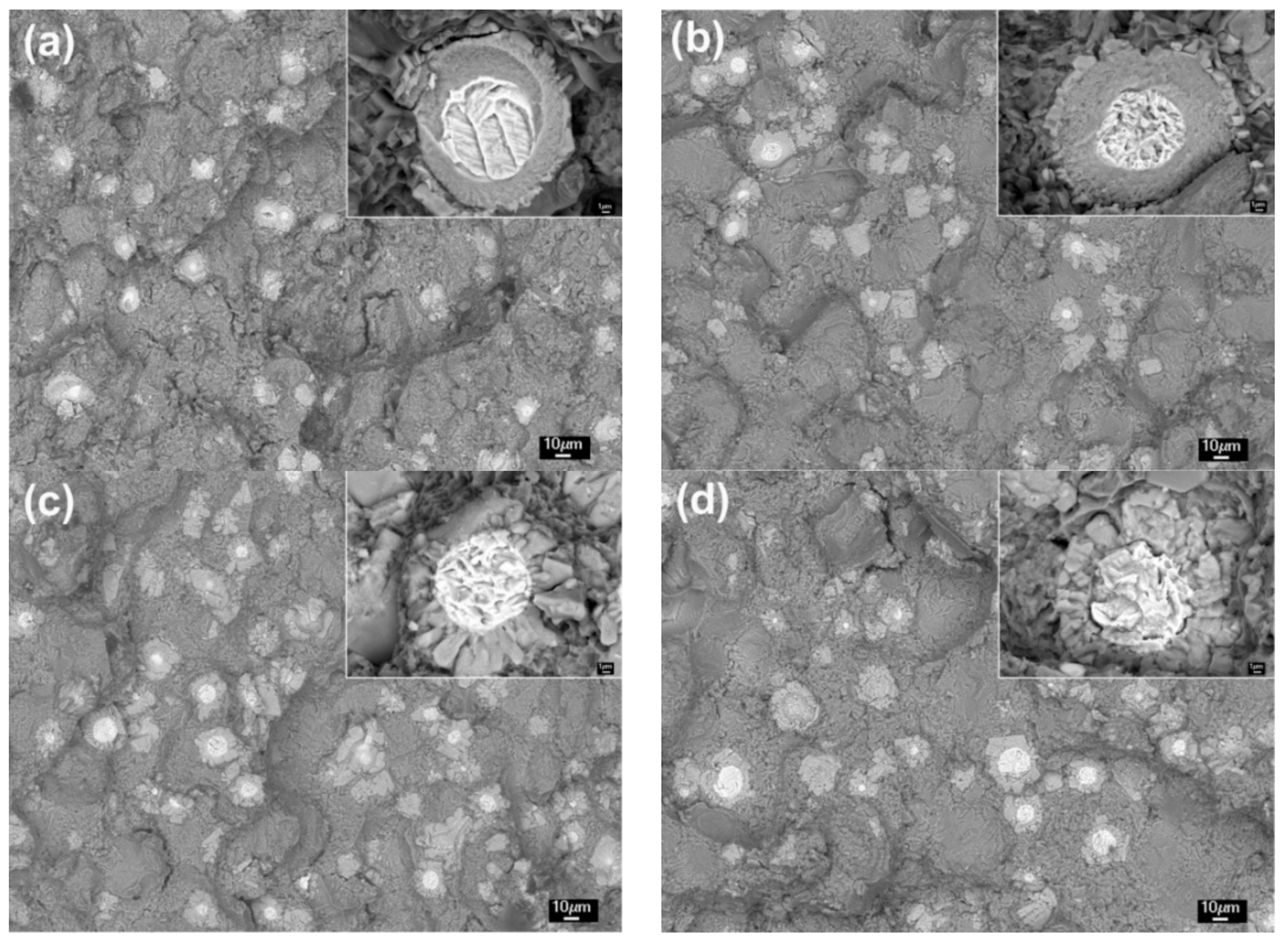
Figure 9). The number of the visible reinforcements can thereby reflect the crack propagation path within the 3Ss. For this purpose, the fracture surfaces were also observed by back-scattered electron (BSE) imaging technology, as shown by
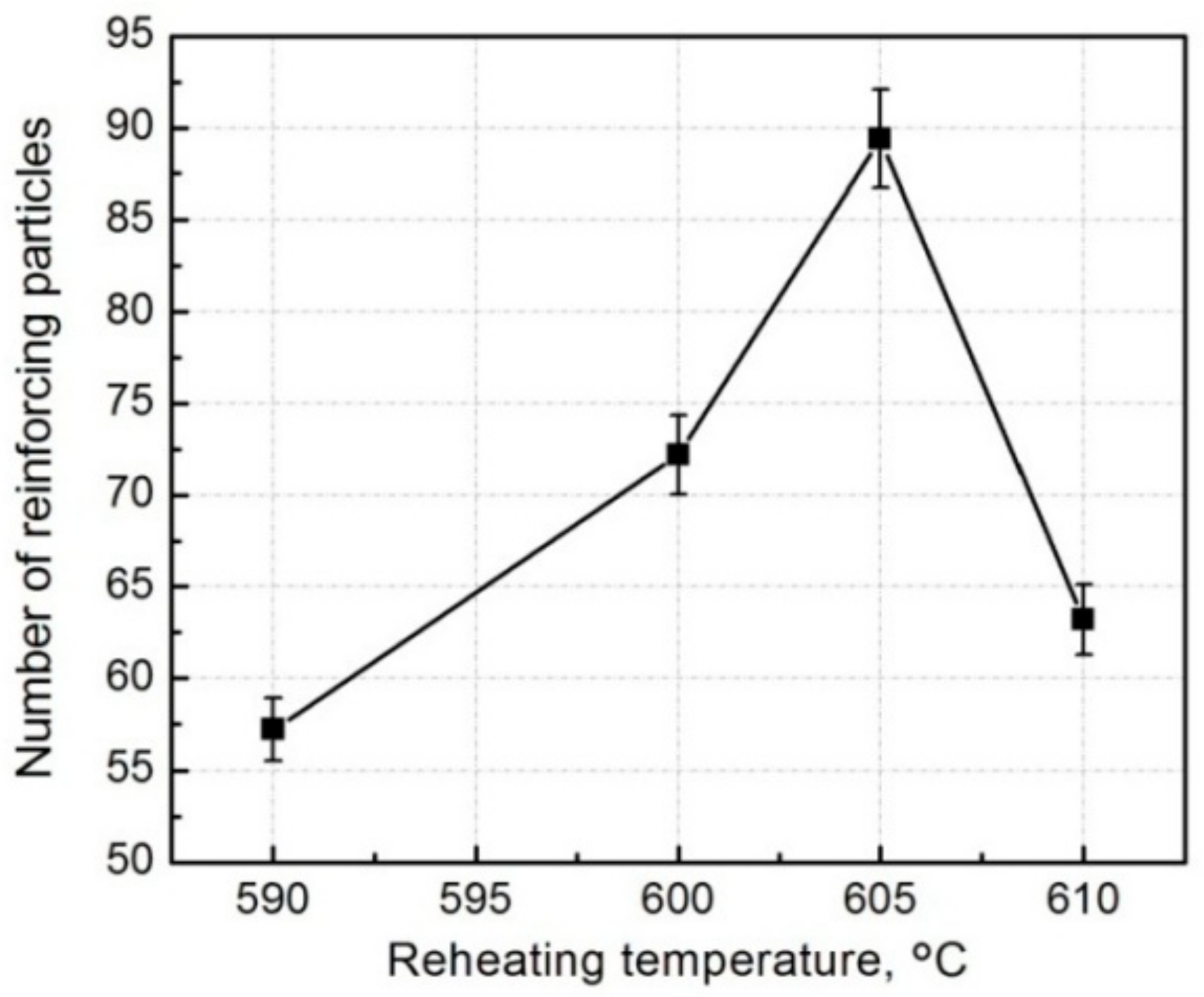
Figure 11, which intuitively indicates that the number of the visible reinforcements increases as the temperature rises from 590 °C to 605 °C and then decreases when the temperature further rises. The quantitative examination more clearly shows this change tendency (
Figure 12). According to the crack propagation discussed above, it can be expected that the number of reinforcements that cracks encounter during their propagation increases with elevating the temperature. But when the temperature rises to a given value, the number then decreases due to the increased 3Ss amount, although cracks still develop along the 3Ss. Based on this analysis, the results from
Figure 11 and
Figure 12 can be well understood. This further confirms the variation of crack propagation path with the reheating temperature resulted from
Figure 10. In addition, the microstructures, especially the shell’s microstructure of the reinforcements can be more clearly observed from the inserts in
Figure 11, the shells in the composites thixoformed at 590 and 600 °C are quite compact and the shell in the former composite is thinner than that in the later one, but those in the composites formed at 605 °C and 610 °C have cracks, or are in particle-agglomerates, due to cracking and peeling off.
In general, the tensile properties increase as the reheating temperature rises from 590 °C to 600 °C due to the enhanced strengthening role from the thickened compact shells and densified matrix microstructure, and then decrease when the temperature exceeds 600 °C because of the impaired strengthening effect from the fracture and peeling of the shells, loosened matrix microstructure and coarsened primary particles. The composite formed at 600 °C has peak properties, UTS of 371 MPa, YS of 268 MPa, and an elongation of 8.3%. The visible reinforcing particles on the fracture surfaces always fracture across their center cores, but for the composite formed at 610 °C, some of them fracture only across the outside shells and the cores debond from the outside shells. The failure modes of the reinforcing particles are determined by their microstructures. The number of the visible reinforcements increases as the temperature rises from 595 °C to 605 °C, but then decreases. This change is depended on the variation of matrix microstructure dominated by 3Ss amount and the feature of crack propagation along the 3Ss.
3.3. Fracture Process and Toughening Mechanism
Figure 13 presents the typical images from in situ tensile testing. It shows that severe plastic deformation occurs in the matrix ahead of the primary crack, resulting in the obvious slip bands (marked by arrow A in
Figure 13a). It is just due to the plastic deformation that large stress concentration generates at the reinforcement/matrix interfaces, and small voids then form when the stress is up to a given value (marked by arrows B). As discussed in
Section 3.2, the 3Ss are the weak points of the composite, and thus, small voids can also generate in these sites (marked by arrows C). When cracks encounter reinforcement, it will change its propagation direction and bypass the reinforcement (marked by arrow D). So it is suggested that cracks can sometimes bypass the encountered reinforcements, besides frequently propagating across them.
In addition, three kinds of fractured modes of the reinforcements with compact shells are observed in the matrix close to the primary crack. First is that cracks generate between the outer jagged structures and the inner compact shell (
Figure 13b). This implies that the bonding strength between these two structures is relatively weak, and thus debonding can occur between them, as shown by
Figure 13e. Second is that cracks partially develop around the center Ti core (
Figure 13c). This is consistent to the phenomenon shown by
Figure 9a,b, partial debonding occurs between the compound shell and Ti core. Third is that the reinforcement crack between the center core-shell-structured core and the outer cracked shell (
Figure 13d), which is just matched with the result shown by
Figure 8a (marked by arrows D and E) and
Figure 9d. However, in most cases, the reinforcements fracture across Ti core, as indicated by
Figure 13f. This is corresponded to the situations shown by
Figure 9a–c.
Figure 14 also shows some typical morphologies of reinforcements in the composites formed at 590 °C and 600 °C after in situ tensile testing. The reinforcement in
Figure 14a has only four cracks that radially distribute within the compact shell. However, in
Figure 14b, some small cracks appear in the Ti core while the opening gaps of the cracks within the shell are increased.
Figure 14c shows that the sizes of the cracks in Ti core also increase in addition to the further enlargement of the opening gaps of the cracks within the shell, and these two kinds of cracks tend to connect with each other in a zigzag way, resulting in the fracture of the reinforcement across Ti core. According to these changes, it is suggested that the sequence of a, b, and c in
Figure 14 just show the fracture process of a core-shell-structured reinforcement.
Based on the above discussion, the fracture process of the core-shell-structured particle reinforced Al matrix composites can be deduced. Plastic deformation first occurs in the matrix when the stress is up to the yield strength of the composite (marked by arrow A
Figure 13a), resulting in large stress concentration at the reinforcement/matrix interface. Voids then generate at the interface (marked by arrows B) or in the 3Ss (marked by arrows C). Simultaneously, the shells of some reinforcements fracture, forming the radially distributed cracks (
Figure 14a). Subsequently, both the voids and cracks gradually grow up. The voids evolve into cracks and develop along the 3Ss. And the opening gaps of the cracks in shells increase, and severe plastic deformation occurs in the Ti cores and Al matrixes. Lots of small cracks then generate in Ti cores due to working hardening (
Figure 14b) and some of them grow up and finally connect with the cracks in the shells in a zigzag way (
Figure 14c), resulting in the complete fracture of the reinforcements across Ti cores (
Figure 9a–c). Occasionally, cracks in shells do not develop within Ti cores, but bypass the Ti cores along their boundaries, as shown by
Figure 13c. But for the composites reinforced by the reinforcements with cracked shells (i.e., the composites thixoformed at above 600 °C), cracks do not preferentially develop across Ti cores, but propagate between cracked shells and residual cores (
Figure 9d and
Figure 13d). The cracks originated in reinforcements then develop towards the Al matrix after the reinforcements completely fracture. When the cracks originated in either the reinforcements or the matrix grows up to a given degree, they will lose stability and rapidly develop [
28] and finally connect with each other, resulting in the fracture of the composite. During the growth and subsequent propagation, cracks sometimes bypass the encountered reinforcements in terms of debonding between the outer jagged structures and the inner compact shells (
Figure 13b,e).
That is, the first formed cracks in the reinforcements with compact shell are only constrained within the shells. Their sizes are obviously smaller than those generated in monolithic reinforcing particles with the same size to the core-shell-structured ones. So it needs a long process for their sizes to grow up to those of the latter ones due to the hindering effect of the soft Ti cores on their propagation, and thus, quite a large strain should occur for the composite during this process. In addition, the commonly used reinforcements such as SiC, Al
2O
3, TiC, TiB
2, and Al
3Ti are always in an irregular morphology with sharp edges, and large stress concentration generates early at these edges and leads the reinforcements to prematurely fracture [
3,
18,
21]. But for the core-shell-structured reinforcing particles in the present work, their morphology is very spheroidal (
Figure 3a,b and
Figure 14), and thus, stress concentration generated at the interfaces with matrix is relatively small, and thus, their fracture is delayed. Therefore, the deferred formation of cracks and their small size are the main reasons for the ductility improvement of the Al matrix composite reinforced with core-shell-structured reinforcing particles.
In general, small voids always first generate at the interfaces of core-shell-structured particle/Al matrix and in 3Ss during tensile testing. Simultaneously, the shells of some reinforcements also fracture and small cracks generate in the shells in a radial distribution. The small voids then grow into cracks and develop along the matrix, while the opening gaps of the cracks in the shells increase and the Ti cores experience a process of significant plastic deformation, formation and subsequent growth of small cracks, and finally the grown cracks connect with the cracks in the shells in a zigzag way, resulting in the fracture of the reinforcements across the Ti cores. Occasionally, cracks in the shells also develop around the Ti cores. For the composites thixoformed at high reheating temperatures, cracks also propagate between the outer cracked shell and inner core. As the cracks originated from both the matrix and reinforcements grow to a given degree, they then lose stability and rapidly propagate, leading to the fracture of the composite. Cracks sometimes bypass the reinforcing particles along the regions between the outer jagged structures and the inner compact shell. The delayed formation of cracks in the reinforcing particles and their small size are contributed to the ductility improvement of the composite.
3.4. Strengthening Model
At present, all of the existing strengthening models for PRAMCs are aimed at the composites reinforced by monolithic single-phase particles and the most acceptable one to predict YS, σ
cy, is the modified shear lag model (MSL), which is based on the load transfer mechanism, and can be expressed as [
29]:
where σ
0 is the YS of unreinforced matrix alloy; V
p and S is the volume fraction and aspect ratio of reinforcements respectively; Δσ
GR, Δσ
GND, Δσ
TMS, Δσ
SS, and Δσ
OR are the strength increments resulted from grain refinement (GR), geometrically necessary dislocations (GND), thermal mismatch strain (TMS), solid solution (SS), and Orowan strengthening (OS), respectively, due to the introduction of reinforcements, and are presented as [
29,
30]:
where K is the material coefficient and d is the grain size; G is the shear modulus of matrix, ε is the yield strain of composite, and υ is the Poisson ratio of matrix; α is a constant, b is the Burgers vector, ΔT is the temperature interval from room temperature to the processing temperature, d
r is the average diameter of reinforcements, and ΔC is the difference of coefficient of thermal expansion (CET) between matrix and reinforcement; ε’ is the fractional difference in atomic diameter between solute atoms and matrix atoms, and Δx
f is the solute concentration difference between grains in composite and matrix alloy.
As for the multi-phase or multi-structure particle reinforced metal matrix composites, i.e., the core-shell-structured particle reinforced composites, there is only one paper from the authors, which predicted the YS of the Ti@(Al-Si-Ti)
p/A356 matrix composites thixoformed under different reheating durations at 600 °C, based on the above model [
15]. As discussed in
Section 3.2, the strengthening role of this kind of reinforcements varies with the reheating temperature because their microstructure and phase constituent change with the temperature. To make this model suitable to this kind of composites, the authors introduced a coefficient of C to modify the volume fraction of reinforcement V
p and substituted it using the equivalent volume fraction
:
where n is the number of original Ti particles per unit volume, f is the expansion factor during Ti transformation into Al-Si-Ti compounds (using the value of transforming into Al
3Ti), V
1 and V
2 are the volumes of one original Ti particle and residual Ti core in a Ti@(Al-Si-Ti)
p, respectively; A
1 and A
2 are the volume fractions of Al-Si-Ti compounds and Ti core in a Ti@(Al-Si-Ti)
p, respectively, E
1 and E
2 are the elasticity moduli of Al-Si-Ti compounds (using the value of Al
3Ti) and Ti, respectively. The role of OR can be neglected because it has effect only when the reinforcement size is less than 1 μm [
30]. According to Formulas (7) and (9), it can be found that
increases with the increase of shell thickness (i.e., the increase of A
1), and thus, the strengthening role to the matrix is improved. This is consistent with the experimental results from both the present work and Reference [
15], the thicker the compact shells are, the higher the YS will be.
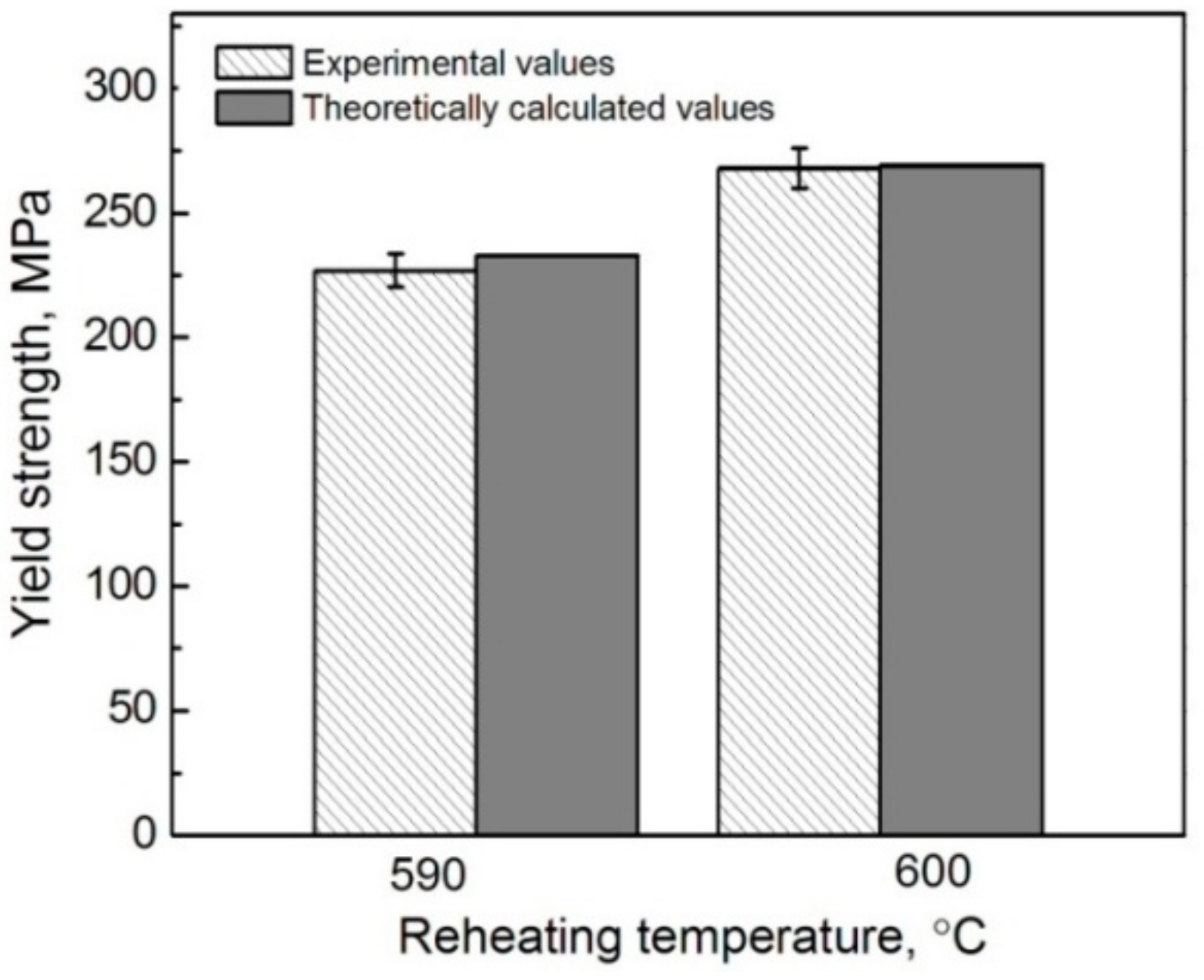
To further verify the rationality of this MSL model modified according to the characteristics of core-shell-structured particle reinforced metal matrix composites, the theoretical calculations were also carried out in this work. In addition, the contributions of each strengthening mechanism subjected to the reheating temperatures were discussed.
Substituting V
p in Formulas (1), (3), and (4) by
, expressed by Formula (7), then incorporating Formulas (2)–(5) into Formula (1), and finally taking the data in
Table 3 and
Table 4 into Formula (1), the YS values of the composites thixoformed at different reheating durations can be obtained. It is noted that only the shells in the composites formed at 590 °C and 600 °C are compact, so the YS values of these two composites were calculated. As shown by
Figure 15, the calculated values are well consistent to the experimental ones, which further confirms that the modified MSL model is actually suitable to predict the YS of this kind of composite, and especially, the considered strengthening mechanisms such as GR, GND, TMS, and SS are also reasonable.
Table 5 gives the respective contributions of GR, GND, TMS, and SS to the strength increment of the composites formed at 590 °C and 600 °C. It is found that the largest contribution is not from the expected reinforcements themselves, but from the SS strengthening of the Ti element, and this contribution is further enhanced as the reheating temperature rises. This implies that the SS strengthening of the Ti element to Al alloy is quite large, although its solid solubility is very small (0.272–0.393 at % at 590–600 °C, as shown in
Table 4 and Al-Ti binary phase diagram [
37]). The contribution increase is attributed to the solubility increase of Ti from 0.272 at % to 0.393 at % as the temperature rises from 590 °C to 600 °C. The strengthening from GR is in the second place at 590 °C, but drops to the third place at 600 °C due to the coarsening of primary particles from 37.4 μm to 44.2 μm. However, the effect of GND is sharply increased and rises to second place because of the improved strengthening role of the reinforcements originating from the thickened shells. As implied by the correction factor of C (Formula (9)), the elastic modulus or stiffness of the reinforcements should increase as their shell thickness increases from 4.8 μm to 8.45 μm (calculated according to (d
r-d
Ti)/2 in
Table 4) with rising the reheating temperature from 590 °C to 600 °C, so the plastic shear strain gradient, and thus, the resulting dislocation density in the matrix surrounding the reinforcements should be enhanced [
38], resulting in the significant increase of Δσ
GND from 9.9 MPa to 17 MPa. In addition, the dislocation density induced by CTE mismatch is also increased due to the enhanced elasticity modulus [
34], so the contribution from the TMS strengthening is also increased.
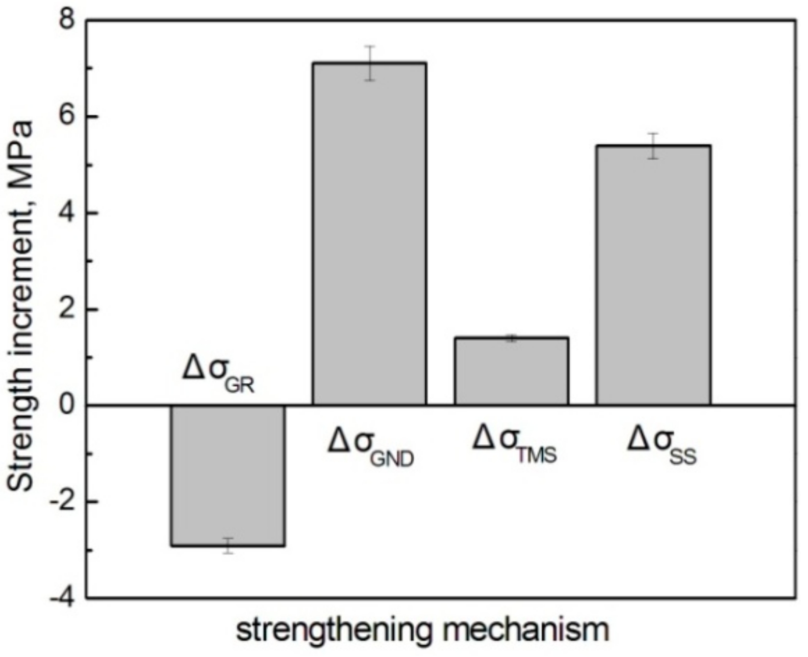
Figure 16 presents the strength increments from the different strengthening mechanisms, which clearly shows that the contribution from GND is the largest, followed by those from SS and TMS, while the contribution from GR is negative.
Therefore, it can be concluded that the modified MSL model that incorporates with the indirect strengthening mechanisms such as GR, GND, TMS, and SS, and introduces a correction factor of C that is actually suitable for accurately predicting the YS of the core-shell-structured Ti@(Al-Si-Ti)p reinforced Al matrix composites. Unexpectedly, the largest contribution to the YS is not the result of the strengthening mechanisms related to the formation of such reinforcements, but from the SS strengthening of Ti element. However, the strengthening from GND is significantly improved as the reheating temperature rises, due to the thickening of the reinforcement compact shells.


