Defect Structure and Oxide Ion Conduction of Potassium Ion Substituted CaWO4
by
 , ,
, ,
Shigeomi Takai
1,* ,
,
Shinya Shitaune
2,
Toshifumi Sano
1,
Hitoshi Kawaji
3,
Takeshi Yabutsuka
1,
Takao Esaka
2 and
Takeshi Yao
4,5 1
Graduate School of Energy Science, Kyoto University, Yoshida-Honmachi, Sakyo-ku, Kyoto 606-8501, Japan
2
Graduate School of Engineering, Tottori University, Koyama-cho Minami, Tottori 680-8552, Japan
3
Laboratory for Materials and Structures, Tokyo Institute of Technology, Nagatsuta-Cho, Midori-ku, Yokohama 226-8503, Japan
4
Institute of Advanced Energy, Kyoto University, Gokasho, Uji, Kyoto 611-0011, Japan
5
National Institute of Technology, Kagawa College, Chokushi-cho, Takamatsu, Kagawa 761-8058, Japan
*
Author to whom correspondence should be addressed.
†
Takao Esaka has died in April, 2018.
Materials 2018, 11(7), 1092; https://doi.org/10.3390/ma11071092
Submission received: 25 May 2018
/
Revised: 16 June 2018
/
Accepted: 19 June 2018
/
Published: 27 June 2018
(This article belongs to the Section Energy Materials)
Abstract
:We have prepared Ca1−xKxWO4−x/2 solid solutions with the Scheelite-type structure to investigate high-temperature electrochemical properties. Room-temperature X-ray diffraction suggested the solid solution range was x ≤ 0.2, since the second phase presumably of K2WO4 was detected for x = 0.3. For all the substituted samples up to x = 0.4, a large jump in conductivity has been observed around 500 °C. At higher temperatures, oxide ion conduction is found to be predominant even for x = 0.4, exceeding the solution limit estimated from the room-temperature XRD. The conductivity at high temperature is essentially proportional to the amount of substituted potassium ions up to x = 0.4, indicating that oxide ion conduction is associated with the formed oxide ion vacancy. High-temperature X-ray diffraction detected no apparent change in lattice parameters around 500 °C for x = 0.1, and the remaining second phase seems to be incorporated into the Scheelite lattice at high temperatures.
1. Introduction
Considerable attention has been focused upon the oxide ion conductors for the application of the electrolyte of SOFC (Solid Oxide Fuel Cell) [1,2,3]. Since the major electrolyte materials of SOFC, such as stabilized zirconia or doped ceria, belong to the Fluorite-type structure; Scheelite-type structured materials derived from the Fluorite-type are a potential candidate for the oxide ion conductors [4]. We have intensively studied the PbWO4-based oxide ion conductors with the Scheelite-type structure [5,6,7,8]. When lanthanum ions are partly substituted into the lead site of PbWO4, forming oxide ion interstitials such as Pb1−xLaxWO4+x/2, high oxide ion conduction appears at elevated temperatures. Such a defect structure has been confirmed by the powder density measurements [6]. On the other hand, CaWO4 with the mineral name of “Scheelite” is unlikely to form a solid solution by lanthanum substitution to create oxide ion interstitials. Nevertheless, in recent years, we have found that Cs-substituted CaWO4 with the form Ca1−xCsxWO4−x/2 exhibits oxide ion conduction at elevated temperatures [9]. Since most oxide ion conductors with the Fluorite-type employ oxide ion vacancy for the oxide ion diffusion, mono-valent ion substitution for CaWO4 would be a promising strategy for exploring the new type of oxide ion conductors. Considering that the ionic radius of the K+ ion (165 pm for 8-coordinate) is closer to that of Ca2+ (126 pm) rather than Cs+ (188 pm) [10], potassium substitution is more appropriate for the solid solution formation with CaWO4. In the present study, we prepared the solid solution of Ca1−xKxWO4−x/2 to investigate the high-temperature electrochemical properties, and thereafter, high-temperature X-ray diffraction experiments were carried out emphasizing the phase transition phenomena.
2. Materials and Methods
Ca1−xKxWO4−x/2 samples were prepared by conventional solid-state reaction method, and were started using CaCO3, H2WO4, and K2CO3. The calcining and sintering temperatures were selected as 800 and 1000 °C, respectively, as per the previous Cs-substituted system [9]. The obtained samples were analyzed by X-ray diffraction with CuKα radiation (XRD-6000; Shimadzu, Kyoto, Japan). Conductivity measurements were carried out by means of two-probe AC method, and oxygen gas concentration cells were constructed using the sample discs as electrolytes to evaluate the charge carrier. Pt electrodes were used for electrochemical measurements. In the present study, TG-DTA (DTG-50; Shimadzu, Kyoto, Japan) experiments up to 1000 °C have also been carried out to investigate the phase transition of the sample.
High-temperature X-ray diffraction experiments (AXS D8 Discover; Bruker, Billerica, MA, USA) up to 700 °C were then carried out for x = 0.1 and 0.4 to investigate the structural variation with temperature. The diffracted X-ray was collected by a 2D-detector in the diffractometer for 180 s per measurement. Lattice parameters were refined by the Rietveld method using RIETAN code [11] assuming the Scheelite-type structure with the space group of I41/a.
3. Results and Discussion
We first carried out the preliminary experiments to check the solid solubility and electric conductivity for various alkaline ion substituted CaWO4s with the form Ca1−xAxWO4−x/2 (A: alkaline ion). From the room-temperature X-ray diffraction experiments, the solid solution limits were determined as x = 0.15, 0.10, 0.20 for Cs-, Rb-, and K-substitutions, respectively. As for Na-substitution, the solid solution cannot be obtained even for x = 0.05. We thus compared the high-temperature electric conductivities in these three compounds substituted by Cs+, Rb+ and K+ ions fixing the concentration as x = 0.1. Figure 1 compares the Arrhenius plots of conductivity for various alkaline ion substituted samples of Ca1−xAxWO4−x/2 (x = 0.1). While the Cs-substituted system gradually decreases the conductivity with reducing temperatures, the Rb- or K-substituted systems keep the relatively higher conductivity down to the intermediate temperatures with a drop in conductivity around 600 or 500 °C. On the other hand, all the substituted systems possess the similar conductivities as well as the similar slopes above 900 °C. Namely, keeping the higher conductivity down to the intermediate temperature exhibits for the K-substituted system. Accordingly, we carried out the electrochemical and structural studies focusing on the K-substituted CaWO4.
Figure 2 shows the X-ray diffraction patterns of Ca1−xKxWO4−x/2 measured at room temperature. While all the diffraction peaks can be assigned as the Scheelite-type structure for x ≤ 0.2, some additional peaks presumably due to K2WO4 (PDF: 21-1010) or K4WO5 (PDF: 24-0904) are observed at x = 0.3. Therefore, the solid solution range is evaluated as x ≤ 0.2 for Ca1−xKxWO4−x/2. The Arrhenius plots in conductivity measured for Ca1−xKxWO4−x/2 (x = 0–0.4) are represented in Figure 3a. As plotted for x = 0.1 in Figure 1, all the substituted samples exhibit the conductivity enhancement from CaWO4 by more than three orders of magnitude. Moreover, a large jump in conductivity is also observed around 500 °C. It should be noted that, at the higher temperature region, conductivity enhancement continues even after exceeding the solubility limit of x = 0.2. We assumed that excess potassium ions are incorporated into the Scheelite lattice around 500 °C to form oxide ion vacancy as the nominal form of Ca1−xKxWO4−x/2 showing a conductivity jump. DTA measurements were then carried out to investigate this phenomenon. The obtained DTA traces are represented in Figure 4. For x = 0.3 or 0.4, a small endothermic peak is observed around 500 °C in the heating direction, suggesting that formation of the solid solution would occur at this temperature. Moreover, even for x = 0.2, a very small peak is still detected at this temperature.
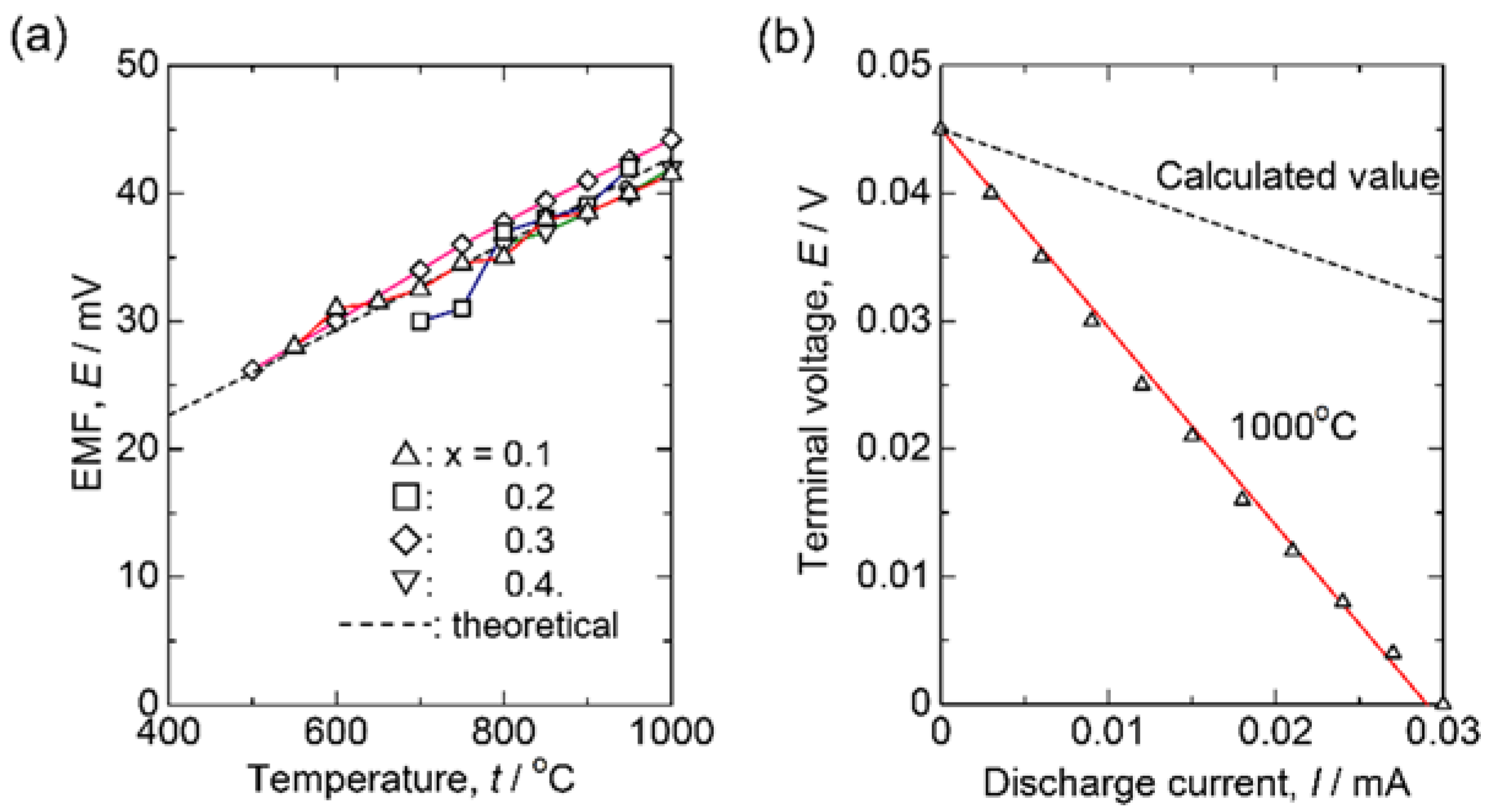
To determine the charge carrier in this system, oxygen gas concentration cells are constructed using the sample as an electrolyte. The anode and cathode gasses selected were air (P(O2) = 0.21 atm) and pure O2. The measured EMFs (Electromotive Forces) are plotted in Figure 5a, where the calculated EMF, assuming Nernst equation, is:
and is indicated by the dashed line. Since the measured EMFs agree well with the calculated one, the predominant charge carrier is not electron but ion. In addition, since the constant current can be drawn from the cell showing linear decrease in terminal voltage with the current as Figure 5b, the charge carrier should be the oxide ions. In Figure 5a, the more interesting aspect is that EMFs obtained for the x = 0.3 or 0.4 beyond the solution limit also coincide with the Nernstian value. To clarify the compositional dependence of the conductivity, the measured electric conductivity is plotted versus potassium concentration as in Figure 3b. At 400 °C, conductivity increases with the potassium composition up to x = 0.3, followed by a drop at x = 0.4. However, the linear relationship between conductivity and potassium concentration can be seen at 600 or 800 °C. Therefore, excess potassium ions are supposed to be incorporated into the Scheelite lattice to form oxide ion vacancy around 500 °C, which allows the high oxide ion diffusion.
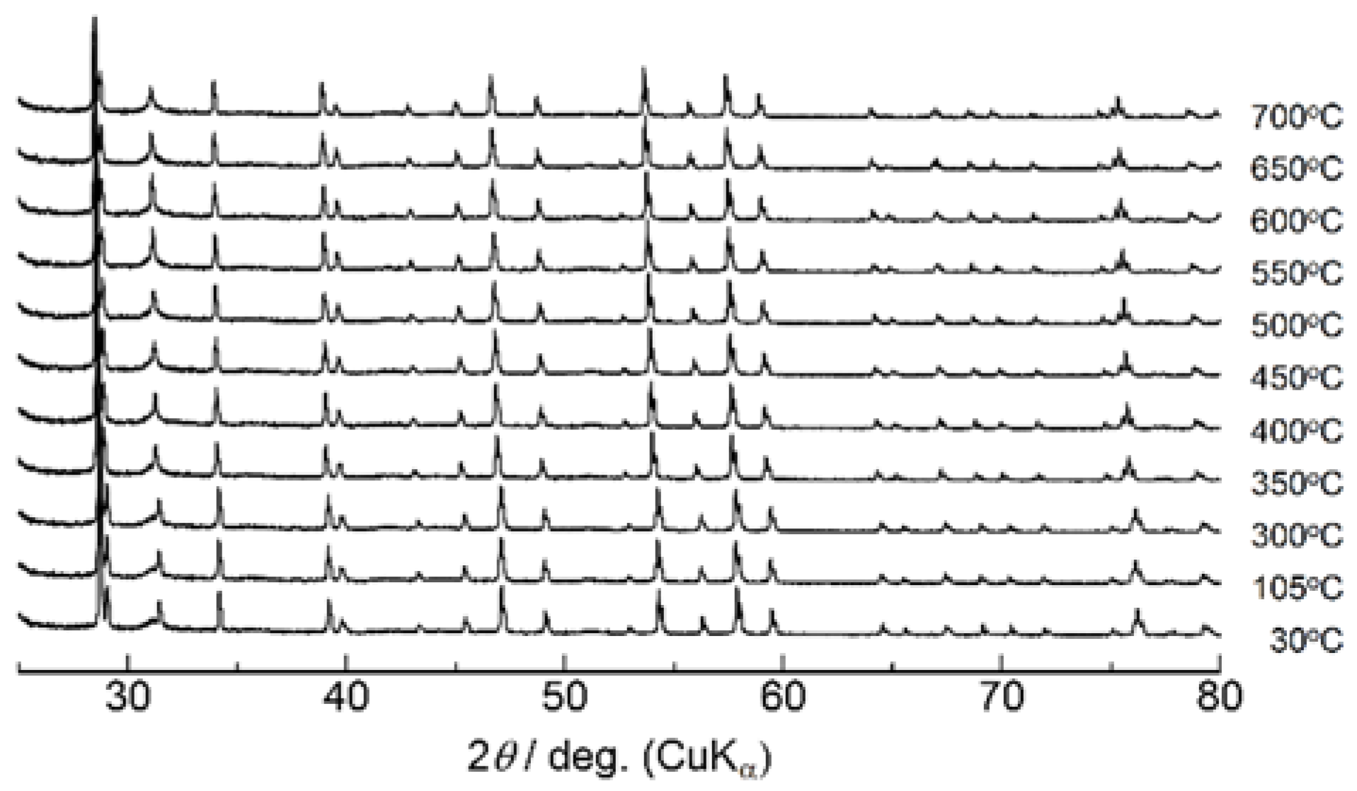
High-temperature X-ray diffraction experiments were then performed focusing upon the conductivity jump accompanied by the endothermic heat at 500 °C. Figure 6 shows the XRD patterns of Ca1−xKxWO4−x/2 (x = 0.1) measured at various temperatures. While diffraction peaks shift toward a lower diffraction angle with temperature due to thermal expansion, any distinct change in peak was not observed around 500 °C. The lattice parameters obtained by the Rietveld refinements are plotted versus temperature in Figure 7. Both a- and c-length increase uniformly without any apparent discontinuity, suggesting that the conductivity jump observed around 500 °C is not accompanied by the drastic change in structure or apparent phase transition. On the other hand, for higher potassium introduction as x = 0.4, diffraction peaks of the second phase were detected at room temperature in Figure 8. Excess XRD peak at 2θ = 30.3° does not shift as other peaks associated with Scheelite-type structure, almost diminishing at 700 °C. This temperature is a little higher than that of the conductivity jump with the endothermic peak, which would be due to that undissolved potassium component, which remains even at the measurement of 700 °C. Assuming that the solution range becomes wider at higher temperatures, the residual second phase would dissolve into the Scheelite lattice above 500 °C to create oxide ion vacancies even for x = 0.4, which would directly contribute to the oxide ion conduction. Even though any excess diffraction peak was not detected for x = 0.2 at room temperature, dissolution of a very small amount of potassium ions into the Scheelite lattice might occur for the observed very small endothermic heat at 500 °C. In addition to the solid solution formation, subtle disordering of oxide ions should be considered, which would be made based on the neutron diffraction as a future work.
4. Conclusions
The solid solution range of Ca1−xKxWO4−x/2 is estimated as x ≤ 0.2 from the room-temperature X-ray diffraction experiments, while a slight amount of endothermic heat in DTA trace was observed around 500 °C on heating for x = 0.2. Above this temperature, oxide ion conduction appears to enhance the conductivity by more than three orders of magnitude. High-temperature oxide ion conductivity increases linearly with the potassium substitution beyond the room-temperature solid solution limit to achieve 0.01 Scm−1 at 600 °C for x = 0.4. High-temperature X-ray diffraction suggested any apparent structural change occurs for x = 0.1, while presumably K2WO4 of the second phase dissolves into the Scheelite lattice at 700 °C. K-substituted CaWO4 shows higher conductivity in comparison with the Cs-substituted system at the intermediate temperature of 600 °C.
Author Contributions
S.T. conceived the investigation and wrote the manuscript. S.S. performed the most of electrochemical experiments and T.S. verified partly. H.K. collected the high-temperature XRD data. T.Yt, T.E. and T.Yo contributed to refine the discussion.
Funding
This work was supported by Grant-in-Aid for Scientific Research (C) (17K06016) of the Ministry of Education, Culture, Sports, Science and Technology (MEXT), and in part by the Collaborative Research Project of Materials and Structures Laboratory, Tokyo Institute of Technology.
Conflicts of Interest
The authors declare no conflict of interest.
References
- Brian, C.H.; Angelika, H. Materials for fuel-cell technologies. Nature 2001, 414, 345–352. [Google Scholar]
- Goodenough, J.B. Oxide-Ion Electrolytes. Annu. Rev. Mater. Res. 2003, 33, 91–128. [Google Scholar] [CrossRef]
- Malavasi, L.; Fisher, C.J.; Islam, M.S. Oxide-ion and proton conducting electrolyte materials for clean energy applications: Structural and mechanistic features. Chem. Soc. Rev. 2010, 39, 4370–4387. [Google Scholar] [CrossRef] [PubMed]
- Galasso, F.S. Structure and Properties of Inorganic Solids; International Series of Monographs in Solid State Physics; Pergamon: Oxford, UK, 1970; Volume 7. [Google Scholar]
- Esaka, T.; Minaai, T.; Iwahara, H. Oxide Ion Conduction in the Sintered Ceramics of the System Pb1−xLaxWO4+x/2. Denki Kagaku 1991, 59, 343–344. [Google Scholar]
- Esaka, T.; Mina-ai, T.; Iwahara, H. Oxide ion conduction in the solid solution based on the scheelite-type oxide PbWO4. Solid State Ion. 1992, 52, 319–325. [Google Scholar] [CrossRef]
- Takai, S.; Touda, S.; Oikawa, K.; Mori, K.; Torii, S.; Kamiyama, T.; Esaka, T. Powder neutron diffraction study of Ln-substituted PbWO4 oxide ion conductors. Solid State Ion. 2002, 148, 123–133. [Google Scholar] [CrossRef]
- Takai, S.; Satou, M.; Yoshida, T.; Chikashige, N.; Kita, T.; Esaka, T. Conduction Property of PbWO4-and PbMoO4-based Oxide Ion Conductors in Lower Oxygen Partial Pressures. Electrochemistry 2011, 79, 696–700. [Google Scholar] [CrossRef]
- Takai, S.; Morhishita, Y.; Kondo, Y.; Yao, T.; Yabutsuka, T.; Esaka, T. Electrochemical properties of Cs-substituted CaWO4 and BaWO4 oxide ion conductors. J. Ceram. Soc. Jpn. 2016, 124, 819–822. [Google Scholar] [CrossRef]
- Shannon, R.D. Revised effective ionic radii and systematic studies of interatomic distances in halides and chalcogenides. Acta Cryst. A 1976, 32, 751–767. [Google Scholar] [CrossRef] [Green Version]
- Izumi, F.; Momma, K. Three-dimensional visualization in powder diffraction. Solid State Phenom. 2007, 130, 15–20. [Google Scholar] [CrossRef]
Figure 1.
Arrhenius plots of conductivity for Ca0.9A0.1WO3.9. △: A = K, ☐: Rb, and ▽: Cs. Conductivity of the pristine CaWO4 is also plotted by closed circles (●).
Figure 1.
Arrhenius plots of conductivity for Ca0.9A0.1WO3.9. △: A = K, ☐: Rb, and ▽: Cs. Conductivity of the pristine CaWO4 is also plotted by closed circles (●).

Figure 2.
X-ray diffraction patterns of Ca1−xKxWO4−x/2 obtained at room temperature.

Figure 3.
(a) Arrhenius plot of conductivity for Ca1−xKxWO4−x/2. ●: x = 0, △: 0.1, ☐: 0.2, ¯: 0.3, and ▽: 0.4; (b) Conductivity isotherms of Ca1−xKxWO4−x/2 at 400, 600, and 800 °C.
Figure 3.
(a) Arrhenius plot of conductivity for Ca1−xKxWO4−x/2. ●: x = 0, △: 0.1, ☐: 0.2, ¯: 0.3, and ▽: 0.4; (b) Conductivity isotherms of Ca1−xKxWO4−x/2 at 400, 600, and 800 °C.

Figure 4.
DTA traces of Ca1−xKxWO4−x/2. Red arrows indicate the small endothermic peak observed in the heating direction.
Figure 4.
DTA traces of Ca1−xKxWO4−x/2. Red arrows indicate the small endothermic peak observed in the heating direction.

Figure 5.
(a) EMFs of the oxygen gas concentration cells as follows using Ca1−xKxWO4−x/2 sample discs as the electrolyte. Air (P(O2) = 0.21 atm) | Ca1−xKxWO4−x/2 | O2 gas (P(O2) = 0.21 atm). △: x = 0.1, ☐: 0.2, ¯: 0.3, and ▽: 0.4. Dashed line denotes the Nernstian value; (b) Discharge plot of the oxygen gas concentration cell employing Ca1−xKxWO4−x/2 (x = 0.1) measured at 1000 °C. The calculated line was assuming only the ohmic loss.

Figure 6.
X-ray diffraction patterns of Ca1−xKxWO4−x/2 (x = 0.1) measured at high temperatures up to 700 °C.
Figure 6.
X-ray diffraction patterns of Ca1−xKxWO4−x/2 (x = 0.1) measured at high temperatures up to 700 °C.

Figure 7.
Temperature dependence of the lattice parameters of Ca1−xKxWO4−x/2 (x = 0.1).

Figure 8.
(a) High-temperature X-ray diffraction patterns of Ca1−xKxWO4−x/2 (x = 0.4); (b) Diffraction pattern enlarged in the range 27–33°.
Figure 8.
(a) High-temperature X-ray diffraction patterns of Ca1−xKxWO4−x/2 (x = 0.4); (b) Diffraction pattern enlarged in the range 27–33°.

© 2018 by the authors. Licensee MDPI, Basel, Switzerland. This article is an open access article distributed under the terms and conditions of the Creative Commons Attribution (CC BY) license (http://creativecommons.org/licenses/by/4.0/).
Share and Cite
MDPI and ACS Style
Takai, S.; Shitaune, S.; Sano, T.; Kawaji, H.; Yabutsuka, T.; Esaka, T.; Yao, T. Defect Structure and Oxide Ion Conduction of Potassium Ion Substituted CaWO4. Materials 2018, 11, 1092. https://doi.org/10.3390/ma11071092
AMA Style
Takai S, Shitaune S, Sano T, Kawaji H, Yabutsuka T, Esaka T, Yao T. Defect Structure and Oxide Ion Conduction of Potassium Ion Substituted CaWO4. Materials. 2018; 11(7):1092. https://doi.org/10.3390/ma11071092
Chicago/Turabian StyleTakai, Shigeomi, Shinya Shitaune, Toshifumi Sano, Hitoshi Kawaji, Takeshi Yabutsuka, Takao Esaka, and Takeshi Yao. 2018. "Defect Structure and Oxide Ion Conduction of Potassium Ion Substituted CaWO4" Materials 11, no. 7: 1092. https://doi.org/10.3390/ma11071092
Note that from the first issue of 2016, this journal uses article numbers instead of page numbers. See further details here.