Article

The Particle Shape of WC Governing the Fracture Mechanism of Particle Reinforced Iron Matrix Composites

1
School of Materials Science and Engineering, Kunming University of Science and Technology, Kunming 650093, China
2
College of Materials Science and Engineering, Chongqing University, Chongqing 400030, China
*
Authors to whom correspondence should be addressed.
Materials 2018, 11(6), 984; https://doi.org/10.3390/ma11060984
Submission received: 18 April 2018 / Revised: 2 June 2018 / Accepted: 8 June 2018 / Published: 11 June 2018
(This article belongs to the Special Issue Damage Detection and Characterization of High Performance Composites)

Abstract

:
In this work, tungsten carbide particles (WCp, spherical and irregular particles)-reinforced iron matrix composites were manufactured utilizing a liquid sintering technique. The mechanical properties and the fracture mechanism of WCp/iron matrix composites were investigated theoretically and experimentally. The crack schematic diagram and fracture simulation diagram of WCp/iron matrix composites were summarized, indicating that the micro-crack was initiated both from the interface for spherical and irregular WCp/iron matrix composites. However, irregular WCp had a tendency to form spherical WCp. The micro-cracks then expanded to a wide macro-crack at the interface, leading to a final failure of the composites. In comparison with the spherical WCp, the irregular WCp were prone to break due to the stress concentration resulting in being prone to generating brittle cracking. The study on the fracture mechanisms of WCp/iron matrix composites might provide a theoretical guidance for the design and engineering application of particle reinforced composites.

Graphical Abstract

1. Introduction

Recently, particle reinforced metal matrix composite coating (also named particle reinforced metal matrix surface composites, PRMMSC) has attracted extensive attentions because a metal surface without coating can easily to suffer abrasion causing the degradation or failure of materials [1]. It is necessary and important to improve the surface properties such as mechanical properties (like strength, toughness and wear-resistance) and chemical properties (corrosion-resistance and oxidation-resistance) for prolonging the service life or minimizing loss of production [2,3,4,5,6,7,8,9,10]. Recently, the WCp/iron matrix surface composites have been extensively used in slurry pump, slurry elbow pipe, liner plate, roll fitting and so forth. These composites can be fabricated by cast infiltration [2,11,12], powder metallurgy [3], laser cladding [5,6,13,14,15,16,17], and so on, to generate great metallurgical bonding between the surface composite layer and the substrate due to the perfect wettability between WCp and molten ferrous alloy.
In recent years, a large number of researchers have carried out plenty of studies on the mechanical properties of metal matrix composites varying with the particle concentration, particle size, stress state, temperature and so on [2,4,11,18,19,20,21,22,23]. However, particle shape is also one of the most important geometric factors for the reinforcement and it can thus affect the overall performance of composites. It is generally believed that cracks in PRMMSC part manufacturing are crucial to the reliable material properties, especially for the reinforcement particles with different shapes. A finite element method was used to evaluate the effects of particle shape (spheres, regular octahedra, cubes or regular tetrahedra) on the mechanical properties of particle reinforced composites and found that particles with different shapes and equal sizes affected the yield stress at different extent [24]. Rasool et al. discussed the effects of particle shape (spherical and non-spherical particle) on the macroscopic and microscopic linear behaviors (linear elastic, thermoelastic and thermal conduction responses) of particle reinforced composites by numerical methods [25]. Trofimov et al. found that 15 convex polyhedral particle shapes could change the effective elastic properties of particle-reinforced composites predicted using micromechanical homogenization and direct finite element analysis approaches [26].
Therefore, different shapes of reinforced particles can affect the mechanical properties of composites, resulting in different fracture modes for the composites. However, there are various shapes in the actual products of WCp, and they are bound to affect the mechanical properties of composites regarding reinforcement. Thus, in this work, WCp/iron matrix composites were prepared utilizing a liquid sintering technique, and the effects of WC particle shapes (taking spherical particle and irregular particle as examples) on the microstructure, mechanical properties and fracture mechanism for particle reinforced iron matrix composites were investigated in details.

2. Materials and Methods

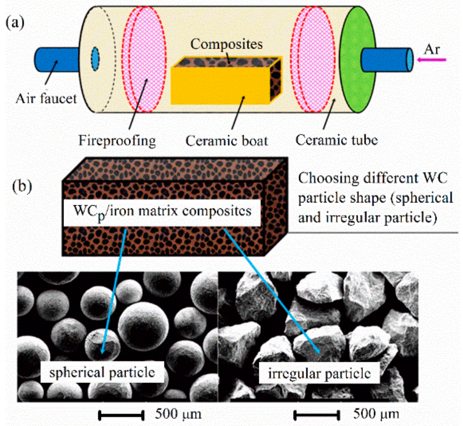
2.1. Preparation of Composites

The WCp/iron matrix composites were prepared utilizing a liquid sintering technique with the raw materials including WCp and iron powders. The XRD pattern of the as-received WC powders is shown in Figure 1. It is clear that the as-received WC particles were composed of W2C, WC and free carbon (C). The schematic diagram of the WCp/iron matrix composites and the morphology of the WCp are illustrated in Figure 2. WCp and iron powders were firstly mixed by XQM-4L planetary ball mill (Nanjing Daran Technology Corporation, Nanjing, China), and it could make sure that WCp would distribute in the iron powder uniformly. After that, the mixed powders were filled into a steel mold and then were pressed to form a green compact by manual hydraulic press with a pressure of 40 MPa for 60 min. The green compact was then placed into a corundum boat (100 mm × 56 mm × 35 mm). Later, it was placed into a tube furnace. The heating schematic diagram of the tube furnace was shown in Figure 2a. The process parameters of composites were described in Table 1. The heating rate of the vacuum tube furnace with a furnace pipe diameter of 80 mm (GSL-1600X, Kejing Company, Hefei, China) was in the range of 0–20 °C/min, operated at 220 V and 5.5 kW. Before being heated, the tube furnace was purged with high pure argon and then exhausted at least three times to protect the samples from pollution, and the vacuum valve was then closed when the pressure reached about 30 MPa. Finally, the heating temperature of the samples was elevated to 1500 °C, and kept for 60 min to make the interface react adequately. These samples were then naturally cooled in the furnace. Accordingly, the WCp/iron matrix composites with different shapes WCp were prepared.

2.2. Characterization

The relative density of composites reinforced by spherical particles and irregular particle was 89.2 ± 1.0 and 88.6 ± 1.0 vol %, respectively. There were no obvious differences within the resolution limits of relative density measurement. The phase composition of these samples was characterized utilizing X-ray diffractometer (XRD, Empyrean, Panalytical Company, Almelo, The Netherlands) with a Cu-Kα radiation operated at 40 kV and 30 mA. These samples were scanned in the 2θ range of 30–90°. Data were collected in a continuous mode with a scanning step of 0.02° and a time interval of 1 s/step. The microstructure of these samples was analyzed with scanning electron microscopy (SEM, VEGA 3 SBH, TESCAN, Brno, Czech Republic) combined with Energy Dispersive Spectrometer (EDS, GENESIS, EDAX, Mahwah, NJ, USA). Hardness of the samples was measured using a Rockwell hardness tester (FR-45, Laizhou Laihua Testing Instrument Factory, Laizhou, China) under a load of 150 kgf (1471 N) with a diamond cone indenter and duration of the test force 10 s. Each test was repeated at least 5 times, the value would be averaged. The compression tests were carried out by utilizing AG-IS 10 KN mechanical testing machine (Shimadzu Corporation, Kyoto, Japan). To ascertain reproducibility, each test result reported in this work was averaged from eight compression test under the same conditions. Finally, the fracture morphology of composites was observed using field emission scanning electron microscopy (FE-SEM, Nova Nano SEM 450, FEI Company, Hillsboro, OR, USA).

3. Results

3.1. Microstructure

The WCp were mainly composed of WC and W2C phase identified by XRD, shown in Figure 1. Referencing the W-C phase diagram and previous theoretical calculations, the temperature of WC decomposition reaction was around 1250 °C [12].
2WC→W2C + C.
The reaction (1) could promote to generate more W2C [19]. The W2C would react with iron to generate Fe3W3C. According to our previous first principles calculation, the cohesive energy Ecoh of reaction between W2C and Fe was −0.01 eV/atom [12].
3Fe + 3/2W2C→Fe3W3C + l/2C.
According to thermodynamic theory, reaction (2) could occur spontaneously when the cohesive energy is negative. These two reactions promoted each other and led to the interface reaction between WCp and iron matrix around 1341 °C. Meanwhile, WCp could decompose partially at a high speed in the heating process, more products of reaction (1) could be generated. The enrichment of W2C could provide more reactants for reaction (2) to finalize more Fe3W3C concentrated in the local area around WCp [27].
Spherical particles and irregular particles were evenly distributed in the matrix, and there was no aggregation. Irregular WCp possessed more prominent edges and corners, while spherical WCp presented regular sphere. The microstructure of prepared WCp/iron matrix composites with different particle shapes was shown in Figure 3. The spherical and irregular WCp presented an integrated interface morphology state, and obvious interface reaction zones were generated in the surrounding, which demonstrated that particles occurred in the metallurgical reaction with iron matrix, shown in Figure 3a. A large number of brittle phase Fe3W3C was presented in the matrix with dispersed state. Comparing Figure 3a,b, the brittle phase Fe3W3C in spherical WCp/iron matrix composites was more homogeneous than that in irregular WCp/iron matrix. A typical magnification view is shown in Figure 3c,d, where plenty of intermittent massive structures appeared in irregular WCp due to the stress concentration, which scattered into the iron matrix. Most W2C in WCp would react with Fe3W3C in WCp/iron matrix composites. The metallurgical reaction (2) occurred between W2C and Fe, while the remaining WC particles distributed in the matrix presenting dark areas. In spherical WCp/iron matrix composites the bright white part (i.e., W2C) of WCp was more, while the dark part was less (i.e., non-dissolved WC). As shown in Figure 3c,d, the brittle phase Fe3W3C presented a block structure in matrix. As shown in Figure 3b, the flat shape WCp in irregular WCp/iron matrix composites tended to be round, and there was a trend turning into regular (spherical) WCp because irregular WCp had many bulges. These bulges would take precedence over some of the other flats or recessed parts, so the irregular WCp had a trend of turning into regular WCp. The thickness of interface was very thin ranging from 5 to 60 μm. The thin interface was beneficial to transmitting the stress from matrix to WCp. How did this kind of reaction zone between interface affect mechanical properties?

3.2. Mechanical Properties

The mechanical properties of WCp/iron matrix composites with different particle shape were tested at least eight times. As shown in Figure 4, the yield strength and hardness of spherical WCp/iron matrix composites were 947.8 ± 50 MPa and 69.5 ± 2.5 HRC, respectively. Under corresponding process parameters, the yield strength and the hardness of irregular WCp/iron matrix composites were 556.8 ± 50 MPa and 59.4 ± 2.5 HRC, respectively.
Apparently, the spherical WCp/iron matrix composites had higher compression yield strength and hardness in comparison with the irregular WCp/iron matrix composites.

4. Discussion

In order to explore the initiation location of the micro-crack under compression test, SEM together with EDS analyses of different fracture location was carried out for spherical and irregular WCp/iron matrix composites. The initiation location of micro-crack in composites was determined by observing the phase composition of fracture location. According to the SEM photographs in Figure 5 and the EDS results summarized in Table 2, we could see that there were different element contents at points 1 and 2 in Figure 5a, with a higher Fe content and otherwise lower W and C content, so it could be speculated that these parts were a matrix of composites. At points 3, 4, 5 and 6, however, the atomic percentages of Fe and W were close to 1:1. Therefore, it could be speculated that the phase could be Fe3W3C, i.e., the location should be the interface of the composites. Micro-cracks could be found near points 3, 4, 5 and 6 in Figure 5a, so it could be inferred that the micro-cracks of spherical WCp/iron matrix composites initiated at the interface.
According to the Figure 5b and Table 2, the main compositions of irregular WCp/iron matrix composites were W and C, at points 7 and 8 in Figure 5b. It could be speculated that the phase was WC and W2C. Thus, the location was WCp of composites. It meant that the brittle cracking occurred during compression tests. Because the convex portions of irregular WCp were easier to produce stress concentration, the particles within composites were prone to cause brittle cracking [22]. The chemical composition of irregular WCp/iron matrix composites at points 9 and 10 could be recognized as Fe3W3C, because the atomic percentages of Fe and W were close to 1:1. This is to say that the location was the interface of composites. Micro-cracks, however, mainly initiated from points 7 and 8 in Figure 5b, so it could be speculated that the micro-cracks of irregular WCp/iron matrix composites initiated from the WCp compound composed of WC and W2C.
Micro-cracks initiated near the interface of different shape WCp/iron matrix composites during compression tests. The micro-cracks extended into large cracks and resulted in the failure of composites. In the compression process, the irregular WCp within composites tended to produce higher stress concentration in comparison with the spherical WCp, which were prone to cause brittle cracking.
The fracture morphology images of WCp/iron matrix composites with different particle shape are shown in Figure 6. From the fracture morphology images of spherical WCp/iron matrix composites in Figure 6a,c, it could be seen that there were not only obvious cleavage steps but also small dimples. However, the number of small dimples was limited, therefore, during compression tests, the fracture mode should be the quasi-cleavage fracture [4,18,28]. From the fracture morphology images of irregular WCp/iron matrix composites in Figure 6b,d, it could be seen that the matrix did not have plastic deformation before breaking, and the section was full of a cleavage step surface, so the fracture mode was a cleavage fracture (brittle fracture). This was because the content of interfacial phase Fe3W3C in the irregular WCp/iron matrix composites was higher than that in the spherical ones, and some Fe3W3C dissociated in the matrix existed as a brittle phase. It would increase the brittleness of composites, and make the spherical WCp/iron matrix composites present the transition mode by way of quasi-cleavage fracture to cleavage fracture [20,21,29]. The micro-cracks initiated and then expanded into a wider crack at the interface, resulting in the failure of the material. The compression strength of brittle fracture mode was lower than that of quasi-cleavage fracture mode for the composites. In this case, the yield strength of spherical WCp/iron matrix composites was 1.7 times of the irregular ones. The fracture surface of these samples after the compression test are shown in Figure 6e,f.
The crack propagation of WCp/iron matrix composites with different particle is schematically illustrated in Figure 7. It could be seen that the micro-cracks source of composites generated near the interface. Cracks initiated at the interface and expanded due to cohesive failure. Cracks could jump from one path to another when the fracture occurred. Several fracture paths might be produced when the cracks propagated through the matrix and encountered WCp. The cracks threaded entire irregular WCp and resulted in the breakage of WCp due to stress concentration. In fact, the irregular WCp had many bulges, resulting in a bigger specific surface area. In the interfacial reaction zones, a more brittle Fe3W3C phase could be generated through diffusion. As discussed above, the brittle Fe3W3C phase was the root of crack initiation. This is to say that an irregular WCp within the composites was prone to cause brittle crack. Therefore, the irregular WCp/iron matrix composites had lower yield strength and hardness.

5. Conclusions

In summary, tungsten carbide particles (WCp) reinforced iron matrix composites with different shapes (spherical particles and irregular particles) were manufactured successfully by utilizing a liquid sintering technique. The effects of WC particle shape on the microstructure, mechanical properties and fracture mechanism for particle-reinforced iron matrix composites were investigated. The following conclusions could be drawn:
(1)
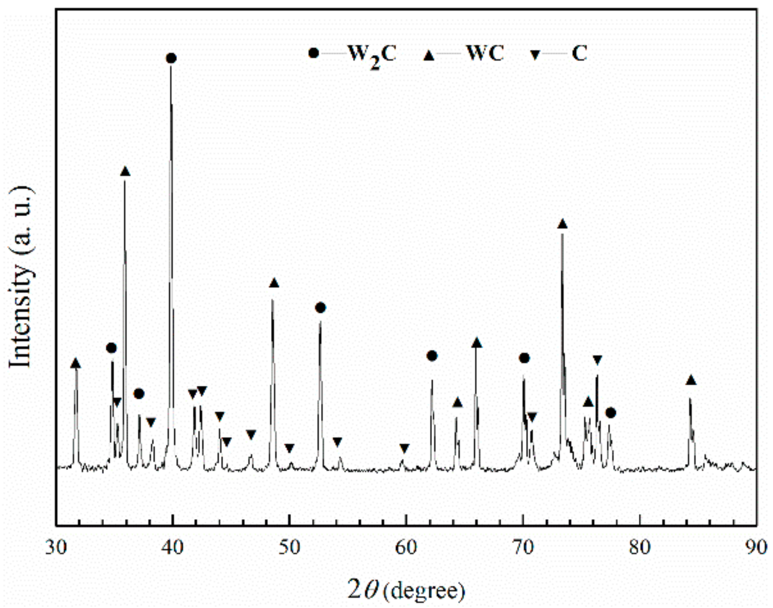
In the interfacial reaction zone, WC particle and iron matrix could react into a brittle Fe3W3C phase.
(2)
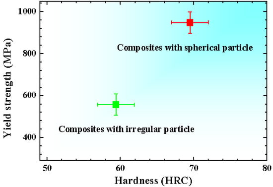
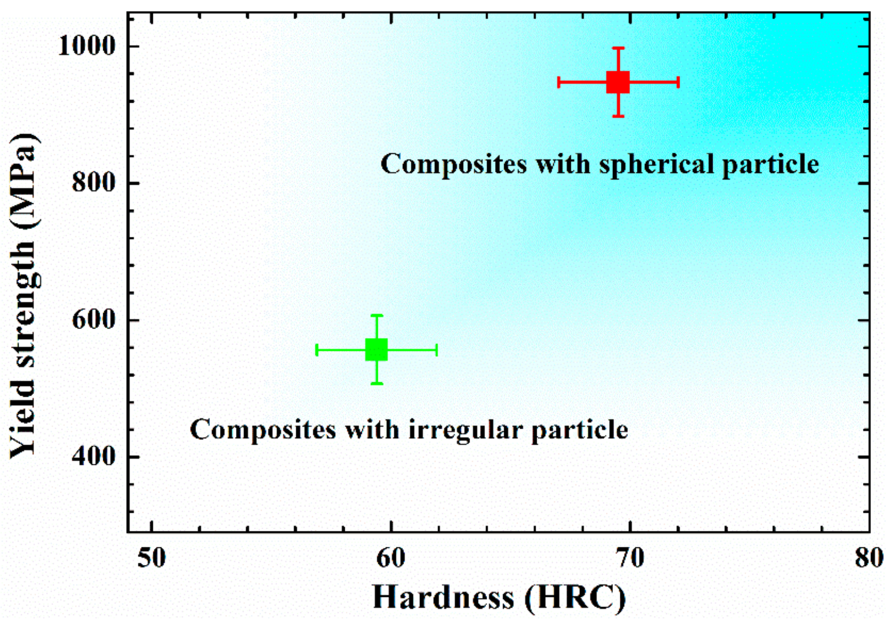
The spherical WCp/iron matrix composites had higher compression yield strength and hardness compared with the irregular ones.
(3)
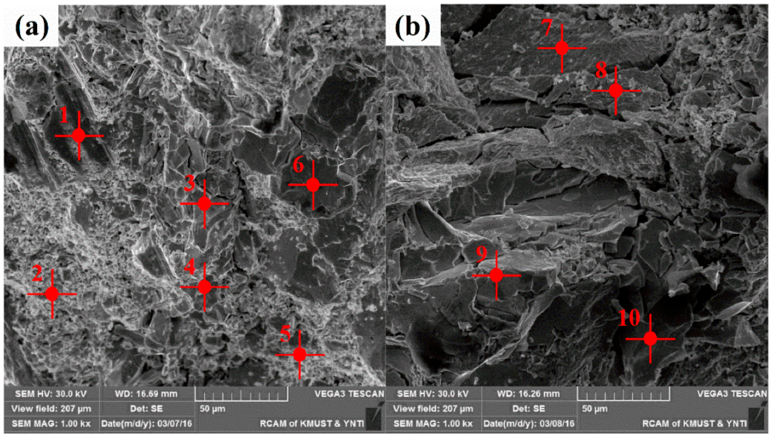
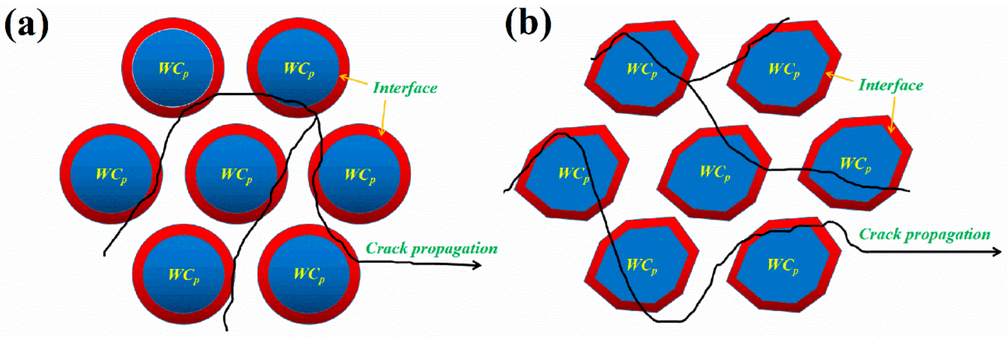
The micro-cracks source of composites were generated at the interface. The irregular WCp within composites tended to produce a higher stress concentration compared with spherical WCp, which were prone to cause brittle fracture.
(4)
Bigger specific surface area resulting from more bulges on irregular WCp could lead to a more brittle Fe3W3C phase in the interfacial reaction zones. Therefore, the irregular WCp/iron matrix composites had lower yield strength and hardness.

Author Contributions

Z.L., Q.S. and J.T. conceived and designed the experiments; Z.L. and P.W. performed the experiments; Z.L., P.W., Q.S. and J.T. wrote the manuscript; All authors analyzed the data and contributed to the enhancement of the manuscript.

Funding

This research was funded by the National Natural Science Foundation of China (51361019, 51561018 and 51501079), the Science Foundation of the Yunnan Provincial Science and Technology Department (2015FD009 and 2017FB081).

Conflicts of Interest

The authors declare no conflict of interest.

Nomenclature

PRMMSCparticle reinforced metal matrix surface composites
WCptungsten carbide particles
a. u.arbitrary units
XRDX-ray diffractometer
SEMscanning electron microscopy
EDSEnergy Dispersive Spectrometer
HRCRockwell C hardness
FE-SEMfield emission scanning electron microscopy

References

  1. Pramanik, A. Developments in the non-traditional machining of particle reinforced metal matrix composites. Int. J. Mach. Tools Manuf. 2014, 86, 44–61. [Google Scholar] [CrossRef]
  2. Li, Z.; Jiang, Y.; Zhou, R.; Chen, Z.; Shan, Q.; Tan, J. Effect of Cr addition on the microstructure and abrasive wear resistance of WC-reinforced iron matrix surface composites. J. Mater. Res. 2014, 29, 778–785. [Google Scholar] [CrossRef]
  3. An, L.; Qu, J.; Luo, J.; Fan, Y.; Zhang, L.; Liu, J.; Xu, C.; Blau, P.J. Aluminum nanocomposites having wear resistance better than stainless steel. J. Mater. Res. 2011, 26, 2479–2483. [Google Scholar] [CrossRef]
  4. Akbari, M.K.; Baharvandi, H.; Mirzaee, O. Nano-sized aluminum oxide reinforced commercial casting A356 alloy matrix: Evaluation of hardness, wear resistance and compressive strength focusing on particle distribution in aluminum matrix. Compos. Part B Eng. 2013, 52, 262–268. [Google Scholar] [CrossRef]
  5. Do Nascimento, A.; Ocelík, V.; Ierardi, M.; De Hosson, J.T.M. Wear resistance of WCp/duplex stainless steel metal matrix composite layers prepared by laser melt injection. Surf. Coat. Technol. 2008, 202, 4758–4765. [Google Scholar] [CrossRef]
  6. Gassmann, R. Laser cladding with (WC + W2C)/Co–Cr–C and (WC + W2C)/Ni–B–Si composites for enhanced abrasive wear resistance. Mater. Sci. Technol. 1996, 12, 691–696. [Google Scholar] [CrossRef]
  7. Zhang, G.-S.; Xing, J.-D.; Gao, Y.-M. Impact wear resistance of WC/Hadfield steel composite and its interfacial characteristics. Wear 2006, 260, 728–734. [Google Scholar] [CrossRef]
  8. Bateni, M.R.; Szpunar, J.; Wang, X.; Li, D. Wear and corrosion wear of medium carbon steel and 304 stainless steel. Wear 2006, 260, 116–122. [Google Scholar] [CrossRef]
  9. Alaneme, K.K.; Odoni, B.U. Mechanical properties, wear and corrosion behavior of copper matrix composites reinforced with steel machining chips. Eng. Sci. Tech. 2016, 19, 1593–1599. [Google Scholar] [CrossRef] [Green Version]
  10. Wang, W.; Wang, D.; Yamaguchi, T.; Nishio, K.; Yan, M.; Li, Y. Comparative study of wear performance of ceramic/iron composite coatings under two different wear modes. Surf. Coat. Technol. 2017, 309, 136–148. [Google Scholar] [CrossRef]
  11. Li, Z.; Jiang, Y.; Zhou, R.; Gao, F.; Shan, Q.; Tan, J. Thermal fatigue mechanism of WC particles reinforced steel substrate surface composite at different thermal shock temperatures. J. Alloys Compd. 2014, 596, 48–54. [Google Scholar] [CrossRef]
  12. Li, Z.; Wei, H.; Shan, Q.; Jiang, Y.; Zhou, R.; Feng, J. Formation mechanism and stability of the phase in the interface of tungsten carbide particles reinforced iron matrix composites: First principles calculations and experiments. J. Mater. Res. 2016, 31, 2376–2383. [Google Scholar] [CrossRef]
  13. Ghosh, S.K.; Saha, P. Crack and wear behavior of SiC particulate reinforced aluminium based metal matrix composite fabricated by direct metal laser sintering process. Mater. Des. 2011, 32, 139–145. [Google Scholar] [CrossRef]
  14. Lin, C.-M. Functional composite metal for WC-dispersed 304L stainless steel matrix composite with alloying by direct laser: Microstructure, hardness and fracture toughness. Vacuum 2015, 121, 96–104. [Google Scholar] [CrossRef]
  15. Fernández, M.; García, A.; Cuetos, J.; González, R.; Noriega, A.; Cadenas, M. Effect of actual WC content on the reciprocating wear of a laser cladding NiCrBSi alloy reinforced with WC. Wear 2015, 324, 80–89. [Google Scholar] [CrossRef]
  16. Wang, J.; Li, L.; Tao, W. Crack initiation and propagation behavior of WC particles reinforced Fe-based metal matrix composite produced by laser melting deposition. Opt. Laser Technol. 2016, 82, 170–182. [Google Scholar] [CrossRef]
  17. You, X.; Zhang, C.; Liu, N.; Huang, M.; Ma, J. Laser surface melting of electro-metallurgic WC/steel composites. J. Mater. Sci. 2008, 43, 2929–2934. [Google Scholar] [CrossRef]
  18. Pu, J.; He, D.; Wang, L. Effects of WC phase contents on the microstructure, mechanical properties and tribological behaviors of WC/a-C superlattice coatings. Appl. Surf. Sci. 2015, 357, 2039–2047. [Google Scholar] [CrossRef]
  19. Shan, Q.; Li, Z.; Jiang, Y.; Zhou, R.; Sui, Y. Effect of Ni Addition on Microstructure of Matrix in Casting Tungsten Carbide Particle Reinforced Composite. J. Mater. Sci. Technol. 2013, 29, 720–724. [Google Scholar] [CrossRef]
  20. Mandel, K.; Radajewski, M.; Krüger, L. Strain-rate dependence of the compressive strength of WC–Co hard metals. Mater. Sci. Eng. A 2014, 612, 115–122. [Google Scholar] [CrossRef]
  21. Mandel, K.; Krüger, L.; Krause, R.; Radajewski, M. The influence of stress state on the compressive strength of WC–Co with different Co contents. Int. J. Refract. Met. Hard Mater. 2014, 47, 124–130. [Google Scholar] [CrossRef]
  22. Timakul, P.; Rattanaprasit, W.; Aungkavattana, P. Improving compressive strength of fly ash-based geopolymer composites by basalt fibers addition. Ceram. Int. 2016, 42, 6288–6295. [Google Scholar] [CrossRef]
  23. Wei, H.; Li, Z.; Shan, Q.; Jiang, Y.; Zhou, R. Effects of WC volume fraction on microstructures and compression performances of WCp/Fe composites. Acta Mater. Compos. Sin. 2016, 33, 2560–2568. [Google Scholar]
  24. Böhm, H.J.; Rasool, A. Effects of particle shape on the thermoelastoplastic behavior of particle reinforced composites. Int. J. Solids Struct. 2016, 87, 90–101. [Google Scholar] [CrossRef]
  25. Rasool, A.; Böhm, H.J. Effects of particle shape on the macroscopic and microscopic linear behaviors of particle reinforced composites. Int. J. Eng. Sci. 2012, 58, 21–34. [Google Scholar] [CrossRef]
  26. Trofimov, A.; Drach, B.; Sevostianov, I. Effective elastic properties of composites with particles of polyhedral shapes. Int. J. Solids Struct. 2017, 120, 157–170. [Google Scholar] [CrossRef]
  27. Wang, L.; Shen, J.; Zhang, Y.; Fu, H. Microstructure, fracture toughness and compressive property of as-cast and directionally solidified NiAl-based eutectic composite. Mater. Sci. Eng. A 2016, 664, 188–194. [Google Scholar] [CrossRef]
  28. Madge, S.; Louzguine-Luzgin, D.; Kawashima, A.; Greer, A.; Inoue, A. Compressive plasticity of a La-based glass-crystal composite at cryogenic temperatures. Mater. Des. 2016, 101, 146–151. [Google Scholar] [CrossRef]
  29. Wang, M.-L.; Yang, B. Fracture mechanism of tungsten fiber reinforced ZrTiCuNiBeNb metallic glass composites. T. Mater. Heat Treat. 2012, 33, 7–11. [Google Scholar]
Figure 1. X-ray diffraction pattern of the as-received WC particles indicating that the particles were composed of W2C, WC and free carbon (C).
Materials 11 00984 g001
Figure 2. A schematic diagram of the preparation of WCp/iron matrix composites. (a) The heating schematic diagram of the tube furnace; (b) The morphology of spherical (left) and irregular (right) WCp.
Materials 11 00984 g002
Figure 3. The metallographic photographs of composites with different particle shape: spherical particle (a,c), and irregular particle (b,d).
Materials 11 00984 g003
Figure 4. The mechanical properties of WCp/iron matrix composites with different particle shape. The error bars in this figure are the 1/2 intervals of the deviation of the minimum and maximum value.
Materials 11 00984 g004
Figure 5. The compression fracture morphology of WCp/iron matrix composites with different particle shape: (a) spherical particle; (b) irregular particle.
Materials 11 00984 g005
Figure 6. The fracture morphology of WCp/iron matrix composites with different particle shape: (a,c,e) spherical particle; (b,d,f) irregular particle.
Materials 11 00984 g006
Figure 7. The crack propagations simulation diagram of WCp/iron matrix composites with different particle shape: (a) Spherical particle; (b) Irregular particle.
Materials 11 00984 g007
Table 1. The process parameters of WCp/iron matrix composites.
Particle ShapeWCp Volume Fraction/%Particles Size/μmHolding Temperature/°CHolding Time/min.
Spherical particle40%300–550150060
Irregular particle40%300–550150060
Table 2. The atomic percentage (at %) of WCp/iron matrix composites with different particle shape.
PointFeWC
185510
28749
3434017
4433918
5433918
6434017
726335
836235
9434017
10434017

