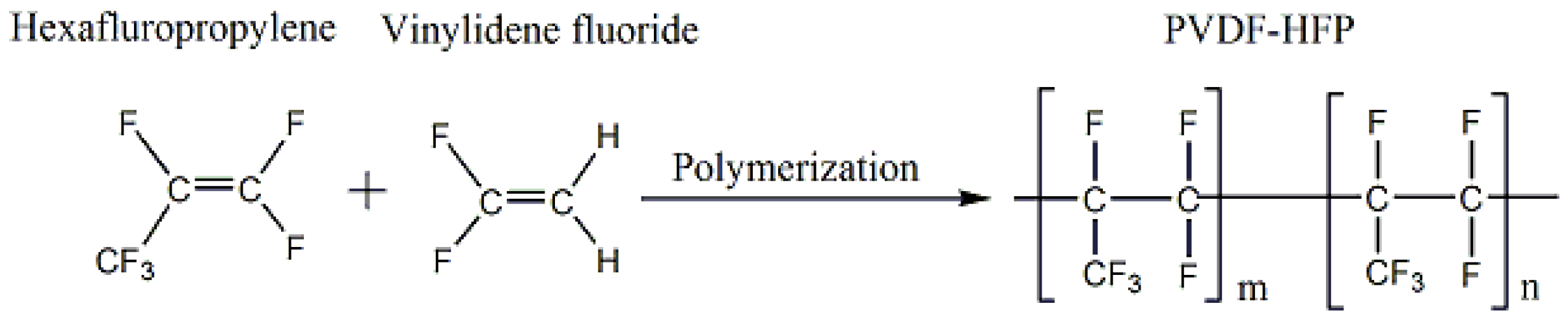
Poly(vinylidene Fluoride-Hexafluoropropylene) Porous Membrane with Controllable Structure and Applications in Efficient Oil/Water Separation


Abstract
:
1. Introduction
2. Experimental
2.1. Materials
2.2. Determination of Phase Diagram
2.3. Fabrication of PVDF-HFP Membrane
2.4. Characterization
2.5. Preparation of Surfactant-Free and Surfactant-Stabilized Water-in-Oil Emulsion
2.6. Surfactant-Free and Surfactant-Stabilized Emulsion Separation Experiments
2.7. Antifouling Performance
3. Results and Discussion
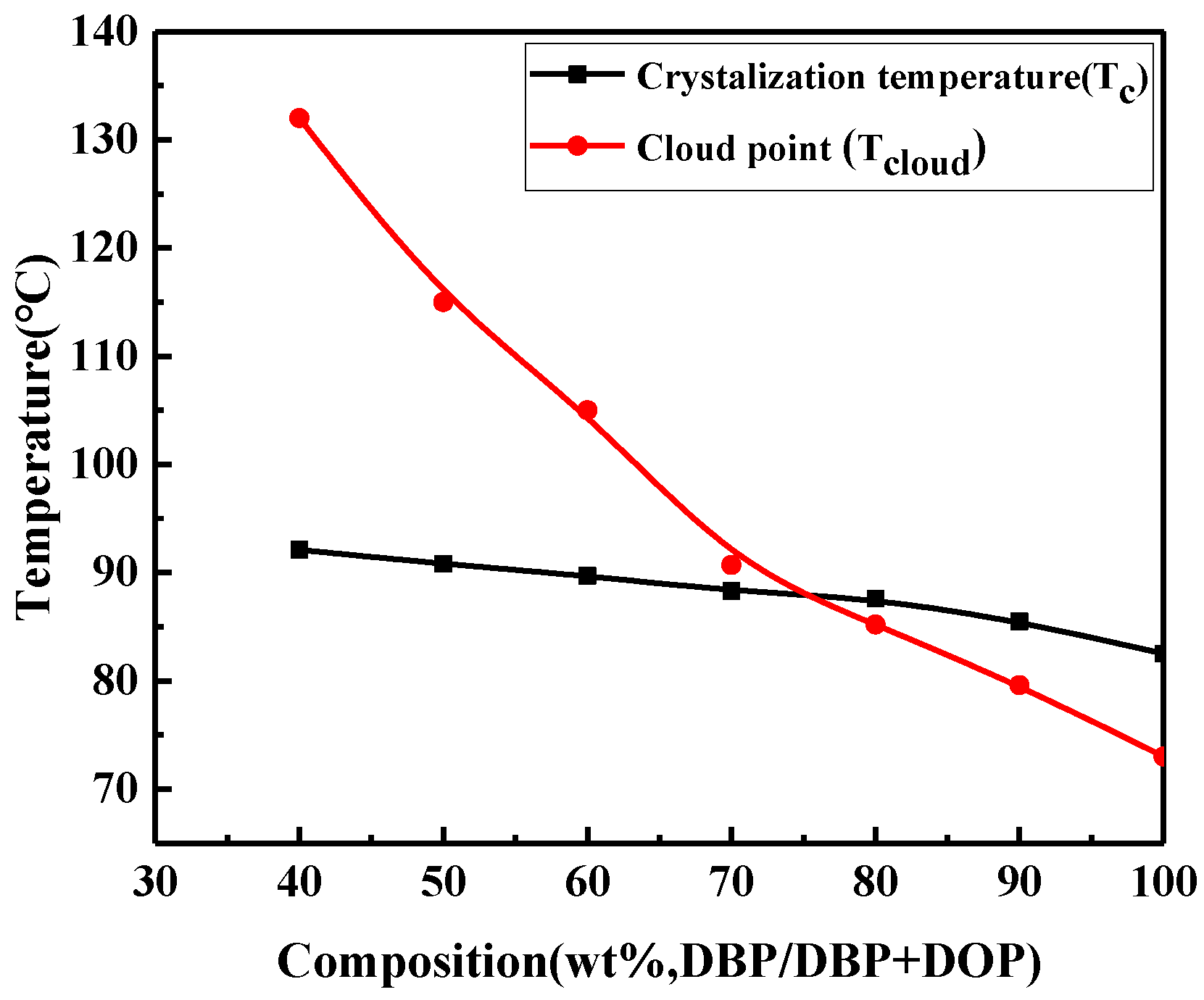
3.1. Phase Diagram
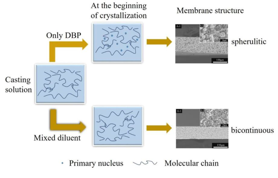
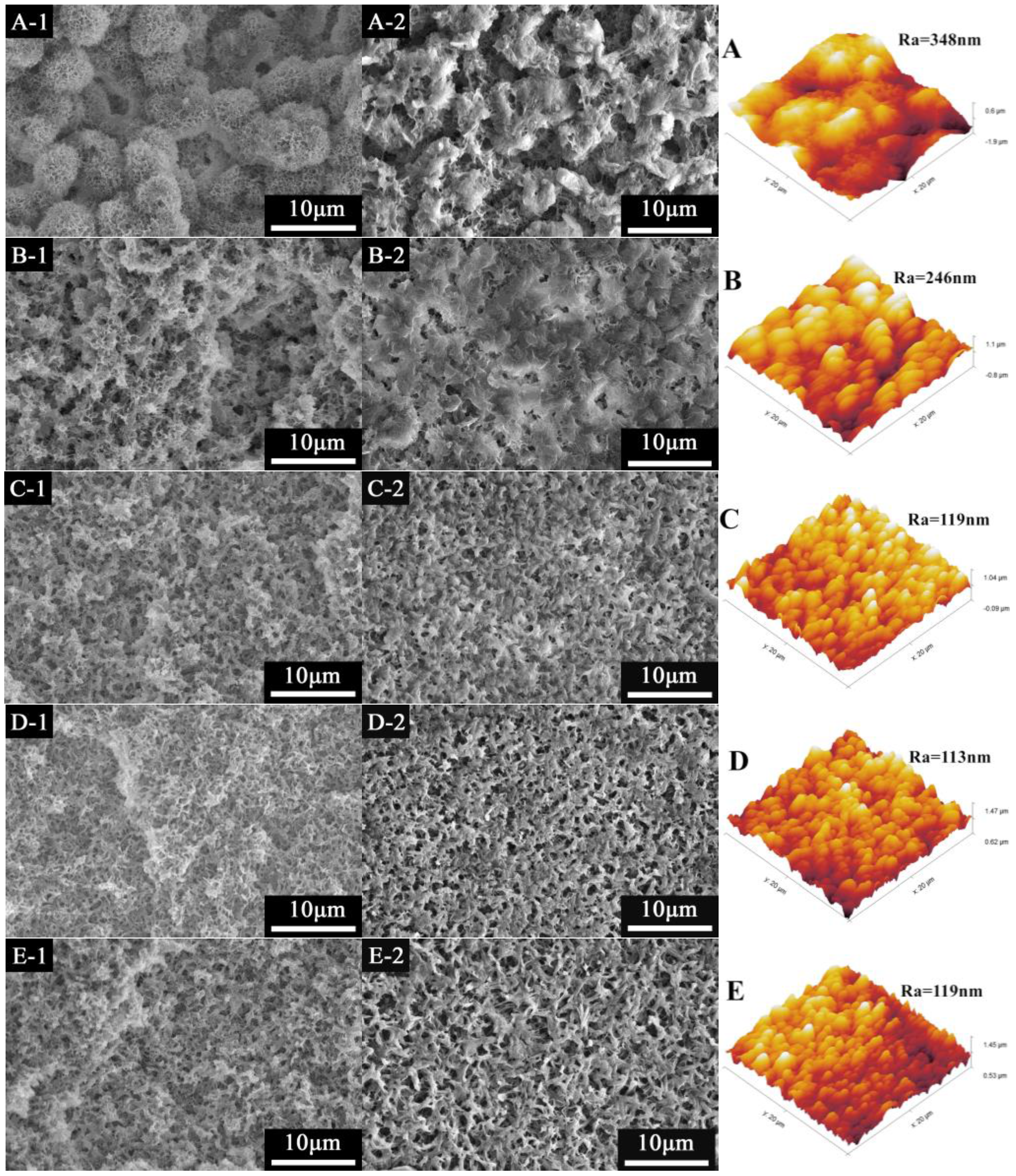
3.2. The Effect of Mixed Diluent Compositions on PVDF-HFP Membranes
3.3. Effect of SiO2 Content on PVDF-HFP Hybrid Membranes
4. Conclusions
Supplementary Materials
Acknowledgments
Author Contributions
Conflicts of Interest
References
- Wypych, G. Handbook of Polymers; Elsevier: Toronto, ON, Canada, 2012. [Google Scholar]
- Lalia, B.S.; Guillen, E.; Arafat, H.A.; Hashaikeh, R. Nanocrystalline cellulose reinforced PVDF-HFP membranes for membrane distillation application. Desalination 2014, 332, 134–141. [Google Scholar] [CrossRef]
- Shi, L.; Wang, R.; Cao, Y.M. Effect of the rheology of poly(vinylidene fluoride-co hexafluropropylene) (PVDF–HFP) dope solutions on the formation of microporous hollow fibers used as membrane contactors. J. Membr. Sci. 2009, 344, 112–122. [Google Scholar] [CrossRef]
- Tian, X.Z.; Jiang, X. Poly(vinylidene fluoride-co-hexafluoropropene) (PVDF-HFP) membranes for ethyl acetate removal from water. J. Hazard. Mater. 2008, 153, 128–135. [Google Scholar] [CrossRef] [PubMed]
- Garcia-Payo, M.C.; Essalhi, M.; Khayet, M. Effects of PVDF-HFP concentration on membrane distillation performance and structural morphology of hollow fiber membranes. J. Membr. Sci. 2010, 347, 209–219. [Google Scholar] [CrossRef]
- Hemmat, A.; Ghoreishi, S.M.; Sabet, J.K. Effect of salt additives on the fabrication of poly(vinylidene fluoride-co-hexafluropropylene) (PVDF-HFP) nanofiber membranes for air Gap membrane distillation. Proc. Mater. Sci. 2015, 11, 370–375. [Google Scholar] [CrossRef]
- Feng, C.S.; Wang, R.; Shi, B.; Li, G.M.; Wu, Y.L. Factors affecting pore structure and performance of poly(vinylidene fluoride-co-hexafluoropropylene) asymmetric porous membrane. J. Membr. Sci. 2006, 277, 55–64. [Google Scholar] [CrossRef]
- Garcia-Fernandez, L.; Garcia-Payo, M.C.; Khayet, M. Effects of mixed solvents on the structural morphology and membrane distillation performance of PVDF-HFP hollow fiber membranes. J. Membr. Sci. 2014, 468, 324–338. [Google Scholar] [CrossRef]
- Stephan, A.M.; Nahm, K.S.; Kulandainathan, M.A.; Ravi, G.; Wilson, J. Poly(vinylidene fluoride-hexafluoropropylene) (PVDF-HFP) based composite electrolytes for lithium batteries. Eur. Polym. J. 2006, 42, 1728–1734. [Google Scholar] [CrossRef]
- Hwang, J.; Jeong, S.K.; Nahm, K.S.; Stephan, A.M. Electrochemical studies on poly(vinylidene fluoride-hexafluoropropylene) membranes prepared by phase inversion method. Eur. Polym. J. 2007, 43, 65–71. [Google Scholar] [CrossRef]
- Li, G.C.; Zhang, P.; Zhang, H.P.; Yang, L.C.; Wu, Y.P. A porous polymer electrolyte based on P(VDF-HFP) prepared by simple phase separation process. Electrochem. Commun. 2008, 10, 1883–1885. [Google Scholar] [CrossRef]
- Wongchitphimon, S.; Wang, R.; Jiraratananon, R. Surface modification of polyvinylidene fluoride-co hexafluoropropylene (PVDF-HFP) hollow fiber membrane for membrane gas absorption. J. Membr. Sci. 2011, 381, 183–191. [Google Scholar] [CrossRef]
- Cui, Z.Y.; Xu, Y.Y.; Zhu, L.P.; Wang, J.Y.; Zhu, B.K. Investigation on PVDF-HFP microporous membranes prepared by TIPS process and their application as polymer electrolytes for lithium ion batteries. Ionics 2009, 15, 469–476. [Google Scholar] [CrossRef]
- Cao, J.H.; Zhu, B.K.; Xu, Y.Y.; Li, J.; Chen, C.X. Preparation and characterization of PVDF-HFP membrane. J. Mracromol. Sci. A 2008, 45, 449–455. [Google Scholar] [CrossRef]
- Ji, G.L.; Zhu, B.K.; Cui, Z.Y.; Zhang, C.F.; Xu, Y.Y. PVDF porous matrix with controlled microstructure prepared by TIPS process as polymer electrolyte for lithium ion battery. Polymer 2007, 48, 6415–6425. [Google Scholar] [CrossRef]
- Li, X.F.; Xu, G.Q.; Lu, X.L.; Xiao, C.F. Effects of mixed diluent compositions on poly(vinylidene fluoride) membrane morphology in a thermally induced phase-separation process. J. Appl. Polym. Sci. 2008, 107, 3630–3637. [Google Scholar] [CrossRef]
- Song, Z.Y.; Xing, M.H.; Zhang, J.; Li, B.A.; Wang, S.C. Determination of phase diagram of a ternary PVDF/γ-BL/DOP system in TIPS process and its application in preparing hollow fiber membranes for membrane distillation. Sep. Purif. Technol. 2012, 90, 221–230. [Google Scholar] [CrossRef]
- Wang, L.; Huang, D.X.; Wang, X.D.; Meng, X.R.; Lv, Y.T.; Wang, X.; Miao, R. Preparation of PVDF membranes via the low-temperature TIPS method with diluent mixtures: The role of coagulation conditions and cooling rate. Desalination 2015, 361, 25–37. [Google Scholar] [CrossRef]
- Sun, C.G.; Feng, X.S. Enhancing the performance of PVDF membranes by hydrophilic surface modification via amine treatment. Sep. Purif. Technol. 2017, 185, 94–102. [Google Scholar] [CrossRef]
- Zhang, W.B.; Shi, Z.; Zhang, F.; Liu, X.; Jin, J.; Jiang, L. Superhydrophobic and superoleophilic PVDF membranes for effective separation of water-in-Oil emulsions with high flux. Adv. Mater. 2013, 25, 2071–2076. [Google Scholar] [CrossRef] [PubMed]
- Wang, J.Q.; Wu, Z.Y.; Li, T.T.; Ye, J.R.; Shen, L.Q.; She, Z.; Liu, F. Catalytic PVDF membrane for continuous reduction and separation of p-nitrophenol and methylene blue in emulsified oil solution. Chem. Eng. J. 2018, 334, 579–586. [Google Scholar] [CrossRef]
- Hou, D.Y.; Ding, C.L.; Li, K.L.; Lin, D.C.; Wang, D.W.; Wang, J. A novel dual-layer composite membrane with underwater-superoleophobic/hydrophobic asymmetric wettability for robust oil-fouling resistance in membrane distillation desalination. Desalination 2018, 428, 240–249. [Google Scholar] [CrossRef]
- Lei, W.W.; Li, H.; Shi, L.Y.; Diao, Y.F.; Zhang, Y.L.; Ran, R.; Ni, W. Achieving enhanced hydrophobicity of graphene membranes by covalent modification with polydimethylsiloxane. Appl. Surf. Sci. 2017, 404, 230–237. [Google Scholar] [CrossRef]
- Cao, J.H.; Zhu, B.K.; Xu, Y.Y. Structure and ionic conductivity of porous polymer electrolytes based on PVDF-HFP copolymer membranes. J. Membr. Sci. 2006, 281, 446–453. [Google Scholar] [CrossRef]
- Van de Witte, P.; Dijkstra, P.J.; Van den Berg, J.W.A.; Feijen, J. Phase behavior of polylactides in solvent-nonsolvent mixtures. J. Polym. Sci. Pol. Phys. 1996, 34, 2553–2568. [Google Scholar] [CrossRef]
- Ji, G.L.; Zhu, L.P.; Zhu, B.K.; Zhang, C.F.; Xu, Y.Y. Structure formation and characterization of PVDF hollow fiber membrane prepared via TIPS with diluent mixture. J. Membr. Sci. 2008, 319, 264–270. [Google Scholar] [CrossRef]
- Kim, J.F.; Jung, J.T.; Wang, H.H.; Lee, S.Y.; Moore, T.; Sanguineti, A.; Drioli, E.; Lee, Y.M. Microporous PVDF membranes via thermally induce phase separation (TIPS) and stretching methods. J. Membr. Sci. 2016, 509, 94–104. [Google Scholar] [CrossRef]
- Lee, C.H.; Johnson, N.; Drelich, J.; Yap, Y.K. The performance of superhydrophobic and superoleophilic carbon nanotube meshes in water-oil filtration. Carbon 2011, 49, 669–676. [Google Scholar] [CrossRef]


| Membrane | PVDF-HFP/wt % | DBP/wt % | DOP/wt % | SiO2/wt % |
|---|---|---|---|---|
| M0 | 30 | 70 | - | - |
| M1 | 30 | 63 | 7 | - |
| M2 | 30 | 56 | 14 | - |
| M3/M3-S0 | 30 | 49 | 21 | - |
| M4 | 30 | 42 | 38 | - |
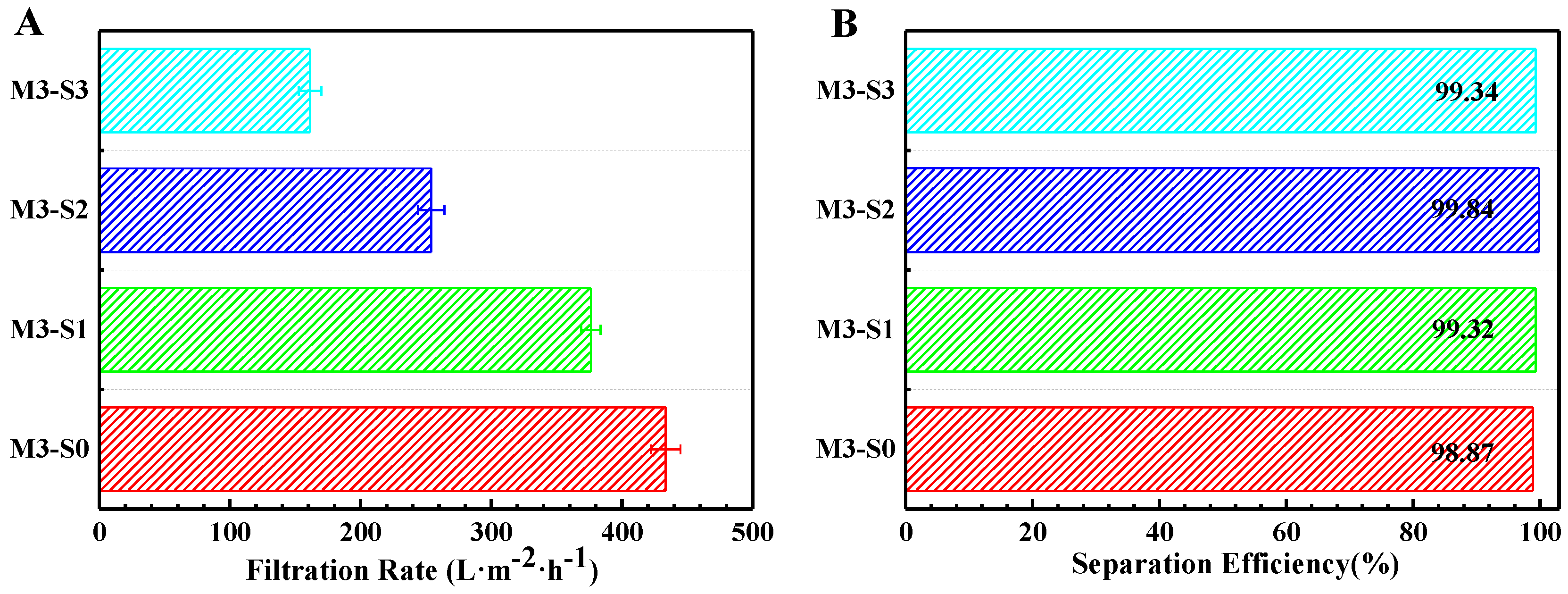
| M3-S1 | 29 | 49 | 21 | 1 |
| M3-S2 | 28 | 49 | 21 | 2 |
| M3-S3 | 27 | 49 | 21 | 3 |
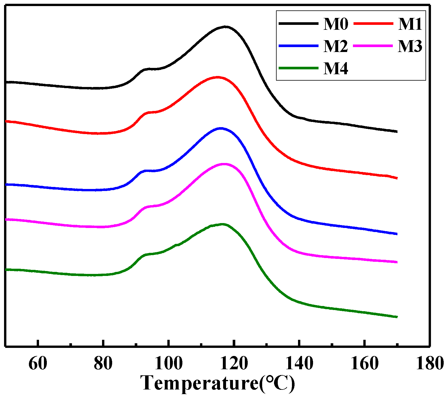
| Membrane | Fusion Enthalpy (J·g−1) | Crystallinity (%) |
|---|---|---|
| M0 | 29.00 | 27.70 |
| M1 | 28.69 | 27.40 |
| M2 | 27.80 | 26.56 |
| M3 | 27.02 | 25.81 |
| M4 | 26.08 | 24.91 |
| Membrane | M0 | M1 | M2 | M3 | M4 |
|---|---|---|---|---|---|
| Filtration rate (L·m−2·h−1) | 894.41 ± 103.33 | 460.42 ± 25.15 | 277.55 ± 17.63 | 497.41 ± 67.27 | 609.43 ± 41.21 |
| Separation efficiency (%) | 75.51 ± 6.72 | 89.21 ± 0.81 | 95.45 ± 0.41 | 99.41 ± 0.12 | 97.56 ± 0.44 |
© 2018 by the authors. Licensee MDPI, Basel, Switzerland. This article is an open access article distributed under the terms and conditions of the Creative Commons Attribution (CC BY) license (http://creativecommons.org/licenses/by/4.0/).
Share and Cite
Wang, X.; Xiao, C.; Liu, H.; Huang, Q.; Hao, J.; Fu, H. Poly(vinylidene Fluoride-Hexafluoropropylene) Porous Membrane with Controllable Structure and Applications in Efficient Oil/Water Separation. Materials 2018, 11, 443. https://doi.org/10.3390/ma11030443
Wang X, Xiao C, Liu H, Huang Q, Hao J, Fu H. Poly(vinylidene Fluoride-Hexafluoropropylene) Porous Membrane with Controllable Structure and Applications in Efficient Oil/Water Separation. Materials. 2018; 11(3):443. https://doi.org/10.3390/ma11030443
Chicago/Turabian StyleWang, Xinya, Changfa Xiao, Hailiang Liu, Qinglin Huang, Junqiang Hao, and Hao Fu. 2018. "Poly(vinylidene Fluoride-Hexafluoropropylene) Porous Membrane with Controllable Structure and Applications in Efficient Oil/Water Separation" Materials 11, no. 3: 443. https://doi.org/10.3390/ma11030443