Article

Ag3Sn Compounds Coarsening Behaviors in Micro-Joints

1
School of Mechanical and Electrical Engineering, Henan University of Technology, Zhengzhou 450052, China
2
George W. Woodruff School of Mechanical Engineering, Georgia Institute of Technology, Atlanta, GA 30332, USA
3
School of Materials Science and Engineering, Huazhong University of Science and Technology, Wuhan 430074, China
*
Authors to whom correspondence should be addressed.
Materials 2018, 11(12), 2509; https://doi.org/10.3390/ma11122509
Submission received: 8 October 2018 / Revised: 6 December 2018 / Accepted: 7 December 2018 / Published: 10 December 2018
(This article belongs to the Section Manufacturing Processes and Systems)

Abstract

:
As solder joints are being scaled down, intermetallic compounds (IMCs) are playing an increasingly critical role in the reliability of solder joints, and thereby an in-depth understanding of IMCs microstructure evolutions in micro-joints is of great significance. This study focused on coarsening behaviors of Ag3Sn compounds in Sn-3.0Ag-0.5Cu (SAC305) micro-joints of flip chip assemblies using thermal shock (TS) tests. The results showed that the Ag3Sn compounds grew and rapidly coarsened into larger ones as TS cycles increased. Compared with such coarsening behaviors during thermal aging, TS exhibited a significantly accelerating influence. This predominant contribution is quantitatively determined to be induced by strain-enhanced aging. Moreover, based on observations for Ag3Sn microstructure evolutions during TS cycling, one particular finding showed that there are two types of coarsening modes (i.e., Ostwald ripening and Necking coalescence) co-existing in the Ag3Sn coarsening process. The corresponding evolutions mechanism was elucidated in a combination of simulative analysis and experimental validation. Furthermore, a kinetic model of the Ag3Sn coarsening was established incorporating static aging and strain-enhanced aging constant, the growth exponent (n) was calculated to be 1.70, and the predominant coarsening mode was confirmed to be the necking coalescence.

1. Introduction

In electronic devices, solder joints generally provide electrical and thermal connections among different components and various circuits, and are regarded as the weakest link in advanced packages of electronic devices [1,2]. Recently, environmental issues and governmental legislation have led to an increased need to implement lead-free solder. In order to achieve this, SnAgCu solders have been recommended as the most promising candidates to replace conventional SnPb solders in microelectronics [3,4]. This is due to their good mechanical properties, adequate wettability, and acceptable melting temperature. Among these SnAgCu solders, the Sn-3.0Ag-0.5Cu (SAC305) alloy has become the benchmark solder as it can be utilized in a wide array of electronic devices [5,6].
In SnAgCu solders, Ag atoms can enhance the thermo-mechanical behaviors and strain rates of the mechanical performance. This is because a large number of finely dispersed Ag3Sn particles, that form by the reaction of Ag and liquid Sn in the reflowing process, restrain the deformation and grain recrystallization of β-Sn subjected to external stressing [7,8]. However, during both storage and service, the microstructure of the SnAgCu solder joints, consisting of β-Sn rich zones, Ag3Sn, and Cu6Sn5 compounds, is susceptible to coarsen over time [9]. The resulting large Ag3Sn particles tend to weaken the mechanical properties of solder joints, thereby degrading their thermal fatigue lifetime [10,11]. It is worth noting that coarsening impacts of Ag3Sn compounds on the mechanical properties are much greater, relative to Cu6Sn5 compounds, owing to their higher volume proportion in the solder joint [12,13]. More significantly, as the size of solder joints scales down, so as to meet miniaturization and multi-functions of electronic devices, the volume proportion of intermetallic compounds (IMCs) in the solder joint has dramatically increased, playing a critical role in joint reliability [14,15]. Hence, the coarsened Ag3Sn particles are expected to exhibit a greater negative impact on the reliability of micro-joints. Consequently, a precise understanding of Ag3Sn coarsening behaviors is of great significance to further evaluate and enhance the reliability of micro-joints.
To date, some research has been conducted into the coarsening behaviors of Ag3Sn compounds over time [16,17]. Most of studies placed their emphasis on thermal aging influences, and found that Ag3Sn coarsening is visible as the aging time increased, indicating that such coarsening behaviors follow the Ostwald ripening principle [13,18]. It is worth noting that the reliability of solder joints with large Ag3Sn particles are significantly sensitive to thermal cycling loading, since thermally induced stresses commonly concentrate at the interface of the solder matrix, and large Ag3Sn particles [19]. This can induce a crack occurrence at the interface, and markedly debase the reliability of solder joints, especially for micro-joints that undergo larger stress [20]. Thermo-mechanical failure of solder joints has recently been reported to be a severe reliability issue in advanced packages [21,22]. However, thus far, considerably few investigations have concentrated on Ag3Sn coarsening behaviors in SnAgCu solder joints subjected to thermal cycling loading, especially for SnAgCu micro-joints, and the relevant coarsening mechanisms are not well understood. Qi et al. used simulated samples with two large solder joints to investigate thermal-shearing influences on Ag3Sn coarsening. They observed that thermal shearing can accelerate Ag3Sn coarsening by comparing this to thermal aging. Furthermore, they presumed that this coarsening phenomenon may be induced by both static aging and strain-enhanced aging in SnAgCu solder joints [23]. Liang et al. found that Ag3Sn compounds exhibited more evident coarsening at higher strain regions of the solder joint during thermal cycling, indicating that strain is capable of promoting Ag3Sn coarsening [24]. Dutta et al. systematically investigated Ag3Sn coarsening behaviors during thermo-mechanical cycling, and revealed that the cumulative strains induced by the ramp time of one cycle, can coarsen Ag3Sn particles. Moreover, they also presented coarsening kinetics based on Ag atomic bulk diffusion [25,26].
Apart from the above descriptions, there is little in the literature that has reported Ag3Sn coarsening in solder joints under thermo-mechanical conditions, and referred to this as having an impact on coarsening behaviors that likely depend on strain-enhanced aging. The contribution of strain-enhanced aging to the Ag3Sn coarsening in the micro-joint has not been evaluated quantitatively under TS cycling. Simultaneously, the microstructure evolutions of Ag3Sn compounds in the coarsening process are not understood well. Accordingly, this lack of understanding does not provide much insight into the physical mechanisms of microstructure coarsening that occurs during thermal cycling. Furthermore, it is essential to establish an adaptive microstructure coarsening model to predict such coarsening behaviors in SnAgCu solder joints. In particular, for the micro-joints in advanced packages, Ag3Sn coarsening is anticipated to become more complicated, due to faster variations of the solder composition, higher thermally induced stresses, and stronger cross-interactions between different metal pads [27,28].
The objective of our research was to systematically investigate coarsening behaviors of Ag3Sn compounds in SAC305 micro-joints of flip chip assemblies using thermal shock (TS) tests. Strain-enhanced influence on the Ag3Sn coarsening was quantified to analyze their size by comparing variations at the different intervals of TS cycling and thermal aging. Combined microstructure observations with finite element simulative analysis were conducted and Ag3Sn microstructure evolutions in the coarsening process are elucidated in detail. Moreover, a kinetic model was established to predict coarsening behaviors that incorporates both static aging and strain-enhanced aging constant. Moreover, we discuss in detail the predominant coarsening mode during TS cycling.

2. Experimental Procedure

The samples used in this study were 10 mm × 10 mm silicon flip chips with a peripheral row of 376 solder bumps at 100 µm pitch and 60 µm diameter, which is a common type used in fine-pitch flip chip assembly. The composition of the solder alloy was Sn-3.0Ag-0.5Cu (wt.%) (SAC305). The flip chips with Ni pads were assembled onto organic substrates with Cu pads by using a standard lead-free thermal reflow profile, i.e., a peak temperature of 240 °C with dwelling approximately 60 s above the solder melting point (217 °C). After cooling, the assemblies were underfilled with an epoxy-based underfill, and cured at 160 °C for 7 min. The electrical resistance of daisy chains was measured to determine assembly quality. The samples were subjected to air-to-air TS testing from −55 °C to 125 °C according to MIL-STD-883H Method 1010.8 Test Condition B, which is a common and preferred way to evaluate the reliability of microelectronic products. Four specimens were extracted at each stage of 0, 400, 800, 1200, and 2000 cycles. Another set of specimens were isothermally aged at 125 °C for up to 500 h in a standard convection oven. Four specimens were extracted at each stage of 0, 100, 200, 300, and 500 h. All specimens were cold-mounted in acrylic, polished down to a 0.05 µm finish, and then etched for 5 s using 5%HCl-95%C2H5OH solution. Backscattered electron (BSE) mode in a scanning electron microscope (SEM, Ultra-60, Zeiss, Oberkochen, Germany) was used to observe the microstructure morphology of the solder joints, and energy-dispersive x-ray spectrometry (EDS, 50mm-SDD, Oxford, Abingdon, UK) was used to characterize the composition and elemental distribution of the IMCs. Image analysis software (MEDIA CYBERNETICS, Oxon, UK) was used to measure and calculate the IMCs size in the solder matrix. Microstructure observations were focused on corner solder joints, since they are recognized as the most critical solder joints of flip chip assemblies due to experience the most strains and stresses during TS cycling [29].

3. Finite Element Analysis Procedure

To further comprehend the microstructure evolutions of the Ag3Sn compounds in the coarsening process, finite element (FE) simulation was conducted to analyze the stress distribution in the corner micro-joint under TS conditions. Considering extremely complicated structures of the micro-joint with irregular morphological IMCs, a two-dimensional model was built to avoid considerable computational expense in this study. A geometry model of the flip chip assembly is presented in Figure 1a. According to the geometric symmetry of this assembly, one-half of this modeling was set up. As shown in Figure 1b, the corner joint was modeled fully since it was anticipated that it would undergo the highest stresses. The others were modeled without considering the IMCs structures to reduce the elements number, and hence the computational time. Based on the IMCs morphological characteristics, the round-shaped structure was used to emulate the Ag3Sn particles into the solder matrix. The FE model is composed of 154,946 quadrilateral elements and 473,282 nodes. Symmetric boundary conditions were defined on the symmetry axis (y axis) of the assembly, and the bottom node at the symmetry axis was completely fixed to prevent free body motion. The stress-free temperature of the solder was assumed to be the melting temperature (220 °C). All the other materials were assumed to be stress-free at 160 °C, which is the underfill curing temperature. The entire assembly was simulated to be cooled down to the room temperature and then subjected to the TS temperature profile. Additional details can be found in [29].
During TS cycling, Sn based solders demonstrated significant viscoplastic deformation owing to high homologous temperature [15]. Anand’s model was used as a unified viscoplastic model can accurately describe viscoplastic behaviors of SAC solders [30]. Therefore, Anand’s model was adopted in this study to simulate viscoplastic deformation behaviors of SAC305 solder, while all other materials were assumed to be linearly elastic. Based on FE theory, element integration point stresses are commonly described by generalized Hooke’ law, {σ} = [D] {εel}, where {σ} is the stress vector, [D] is the elasticity matrix and its value depends on elastic modulus and Poisson’s ratio of materials, and {εel} refers to elastic strains. For linearly elastic materials, {εel} = {ε} − {εth}, where {ε} is total strain vector, and {εth} thermal strain vector. The thermal strain vector can be described as: {εth} = ΔT [αx αy αz 0 0 0]T, where ΔT represents the temperature difference during TS cycling, αx, αy, and αz are coefficient of thermal expansion (CTE) in x, y, and z direction, respectively. For the case of viscoplastic materials, the definition of elastic strain is given by the form of: {εel} = {ε} − {εth} − {εvp}, where εvp is viscoplastic strain vector. According to Anand’s model, the viscoplastic strain rate is described by a flow equation and three evolution equations [15]:
Flow equation:
ε ˙ v p = A [ sinh ( ξ σ s ) ] 1 / m exp ( Q k t )
Evolution equations:
s ˙ = { h 0 ( | B | ) a B | B | } ε ˙ v p
B = 1 s s
s = s ^ [ ε ˙ v p A exp ( Q k t ) ] n
where the nine material constants of A, Q/k, ξ, m, s ^ , n, h0, a, s0 are described in the literature [31], and these constants for SAC305 solder in our FE model can be obtained from the same literature. Furthermore, it was assumed that the CTE of the different materials in our model were all homogeneous and isotropic. The linearly elastic material properties for Ni, Cu, and Ag3Sn are provided in Table 1, and the others can be found in our previous studies [32].

4. Results and Discussion

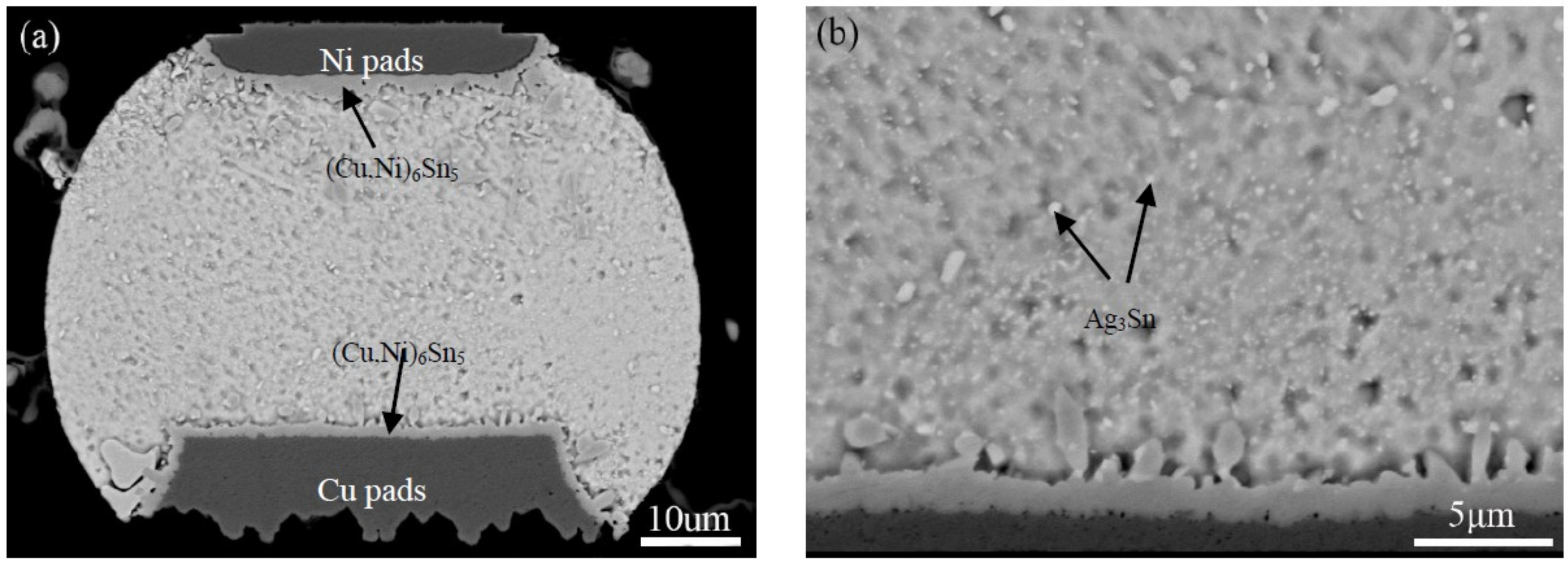
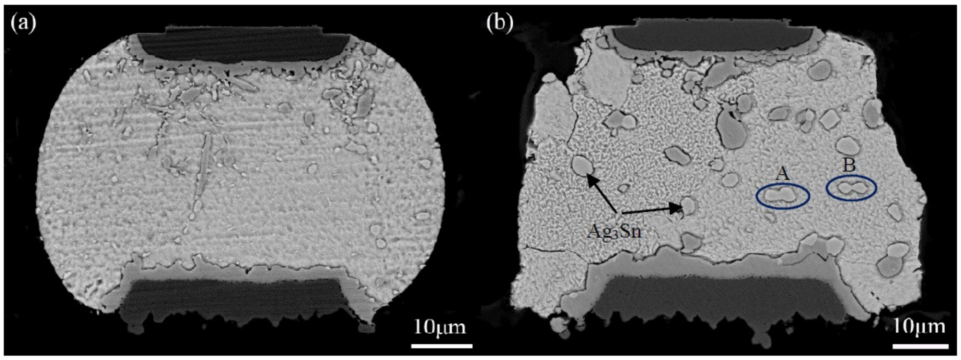
4.1. Coarsening Characteristic of Ag3Sn Compounds during TS Cycling

To definitively elucidate TS cycling effects on Ag3Sn coarsening behaviors, the concept of effective thermal aging time (denoted as teff) was employed to compare the results against isothermal aging. Under the TS conditions in this study, the specimens were dwelled for 15 min at both 125 °C and −55 °C with a 5 s transition time, the diffusion rate of Ag atoms is so low at −55 °C in Sn based solders that it is practically negligible to affect Ag3Sn growth [23]. Consequently, based on the formula of teff (units of s) = ttop × N, where ttop (units of s) is the dwell time at high temperature extreme, and N is the number of elapsed cycle, the specimens would be kept at 125 °C for 100 h under 400 TS cycles, and the magnitude of such Ag3Sn size could be compared against that determined at 100 h using the isothermal aging at 125 °C. Similarly, 300 and 500 h could be used as the effective time for 1200 and 2000 TS cycles. Such an effective thermal aging time has been previously used to investigate the interfacial IMCs growth subjected to thermal cycling loading [23,32].
Figure 2 shows the cross-sectional back-scattered electron (BSE) image of the corner micro-joint after assembly reflow. As seen in Figure 2a, the micro-joint is well shaped with an oval-like shape, and firmly bonded to both the Ni pad of the chip side and Cu pad of the substrate side. Based on the BSE contrast, two types of the IMCs were observed to form at both pad interfaces, as seen in Figure 2a,b. Results of EDS analysis were used to identify the IMCs identity, as presented in Table 2. The dark IMCs, with irregular layer-shape, appeared at the Ni and Cu pad interface (Cu,Ni)6Sn5. A great number of light particle-shaped IMCs dispersed in the solder matrix were Ag3Sn. The cross-sectional BSE images of the corner micro-joints after 500 h aging time and 2000 TS cycles are shown in Figure 3. As we expected, the microstructure evolutions of Ag3Sn compounds displayed an identical trend under these two conditions. Fine Ag3Sn particles became larger in size but fewer in number upon aging time and thermal cycles. However, one discrepancy was still clear, namely that the TS cycling affected more greatly on coarsening behaviors relative to the thermal aging, and thereby exhibiting an effect on the acceleration. Ag3Sn coarsening was reported to depend mainly on both strain-enhanced aging and static aging under thermo-mechanical conditions. Therefore, in the current study, strain-enhanced aging can be responsible for the above-mentioned coarsening acceleration. To further quantify the contribution of strain-enhanced aging to Ag3Sn coarsening during TS cycling, the average diameter of the Ag3Sn particles after isothermal aging and TS cycling, denoted as Diso and DTS, was measured and calculated using digital software. The corresponding data are plotted in Figure 4, it is evident that strain-enhanced aging has the predominant contribution to this coarsening. The contribution rate was calculated to reach as high as above 70% after 2000 cycles according to the formula of (DTSDiso)/DTS × 100. As a consequence, strain-enhanced aging was confirmed to dominate such coarsening behaviors in the SAC305 micro-joints of flip chip assembly when subjected to TS cycling.

4.2. Coarsening Mechanisms of Ag3Sn Compounds

From the viewpoint of Ag3Sn particles transition in size and number, Ag3Sn coarsening behaviors should adhere to the Ostwald ripening principle. This principle is defined as the growth of larger crystals at the expense of smaller ones with the higher interfacial enthalpy, and the driving force of this process originating from the reduction of the total interfacial energy. In the present study, based on this principle, the Ag3Sn coarsening process can be reasonably described as small Ag3Sn particles being dissolved to release Ag atoms, which diffused through the solder matrix to the region around the large ones, and then re-precipitated to facilitate the further growth of the large ones during thermal aging and TS cycling. Furthermore, to explain the extremely remarkable coarsening of the Ag3Sn particles during TS cycling, finite element simulation was employed to analyze the stress distribution in the micro-joints, aiming to correlate it with this phenomenon. Figure 5 shows an accumulative Von-Mises stress contour of the corner micro-joint after eight TS cycles. It is clear that the greater stress mainly distributed around the Ag3Sn particles, these stressed regions appear to form a “stress network” that surrounds the Ag3Sn particles. As is well known, stress is capable of producing substantial crystal defects, such as dislocations and vacancies. These defects can serve as rapid diffusion pathways to drive the atoms diffusion in the solder matrix. Furthermore, existing literature has reported that the volume diffusion of reaction atoms is a governing mechanism for the second phase coarsening that follows the Ostwald ripening principle [25]. Based on these two points, the “stress-network” in the solder matrix seems to provide a fast pathway to accelerate the dissolved Ag atoms diffusion from the smaller Ag3Sn towards the larger ones, thereby leading to the coarsening under thermal cycling conditions.
Interestingly, an extraordinary morphology of the coarsened Ag3Sn particles attracted our attention, marked as A and B in Figure 3. Two adjacent large Ag3Sn particles, with nearly similar size, were observed to come into contact in the shape of a necking, indicating that they are likely to directly coalesce during TS cycling, named as necking-coalescence. Due to only the presence of this coarsening characteristic during TS cycling, the thermally induced stress was naturally taken into account to be the main cause. Figure 6 shows an accumulative Von-Mises stress contour of the corner micro-joint with adjacent and similar-size large Ag3Sn particles after eight TS cycles. The stress concentration appeared on the spaces between the neighboring large Ag3Sn particles. Accordingly, it is reasonable to suppose that the atoms dissolved from the small Ag3Sn particles prefer to diffuse to these higher stressed regions, and then locally pre-precipitated at the larger Ag3Sn particles until it bridged them. This can force a necking to take place in the coarsening process. As the necking formed, remarkable curvature gradients with strong localization at the necking can drive the migration of Ag3Sn grain boundaries, resulting in the establishment of a single particle with uniform curvature at the interface, ultimately a spherical large particle. The detailed process of the necking-coalescing coarsening was drawn in Figure 7. Our experimental results were able to validate such a coarsening process, as seen in Figure 8. It mainly comprises of: The local position of the adjacent particles protruding towards each other; two large particles bridged by a necking; and the necking-shaped Ag3Sn evolves to the uniform curvature at the interface.

4.3. Coarsening Kinetics of Ag3Sn Compounds during TS Cycling

In this section, the emphasis is placed on coarsening kinetics of Ag3Sn compounds under TS conditions, aiming to further elucidate the Ag3Sn coarsening mechanism by developing a coarsening kinetic model, and to determine the predominant coarsening mode. The effective aging time (teff) mentioned in Section 4.1 was introduced into the growth kinetic model of the second phase under isothermal aging [34], and the Ag3Sn coarsening kinetic model during TS cycling can be expressed as follows:
D n D 0 n = k 0 t e f f exp ( Q R T t o p ) = k 0 t t o p N exp ( Q R T t o p )
where D and D0 (units of m) represent the average diameter of the Ag3Sn particles at N and 0 cycles individually, n is the growth exponent, and its value depends on the rate-controlling mechanism, and n = 2 represents the solute atoms transfer across the particle/matrix interface, while n = 3 corresponds to the volume diffusion [35,36]; k0 is the static aging coarsening kinetics constant, Q (units of J/mol) is the activation energy of the relevant diffusion process, and Q = 69 × 103 J/mol for diffusion control mechanism [37], R is the universal gas constant, Ttop (units of K) is the absolute temperature at a high temperature extreme.
As aforementioned, the Ag3Sn coarsening depends on the combined action of the static aging and strain-enhanced aging during TS cycling. Therefore, these two factors were incorporated into this constitutive law. In terms of the model proposed by Dutta’ investigation, 2 M φ γ ˙ t r a m p N , that denoted as ∆t, was introduced to reflect the impact of the strain-enhanced aging on the Ag3Sn coarsening [38]. Combining ∆t with Pang’ concept of the equivalent aging time (denoted as teq, teq = teff + ∆t) [39], teff can be replaced by teq in Equation (5). Accordingly, Equation (5) was revised as Equation (6) as follows:
D n D 0 n = k 0 ( t t o p + 2 M φ γ ˙ t r a m p ) N exp ( Q R T t o p )
where M (units of s) is a kinetic constant representing the strain-enhanced coarsening, ϕ is the ratio of plastic strain to total strain imposed during the ramp, and ϕ ≈ 1 [26], γ ˙ (units of s−1) = γ/tramp is the shear strain rate imposed on the joint during each temperature ramp of TS, γ is the shear strain and can be given in [40], tramp (units of s) is the up or down ramp time during one cycle.
To determine magnitude of coarsening kinetic parameters, including the growth exponent (n) and strain-enhanced coarsening kinetics constant (M), Equation (6) was converted into Equation (7) as follows:
ln d D d N = ln ( k 0 n ( t t o p + 2 M φ γ ˙ t r a m p ) exp ( Q R T t o p ) ) + ( 1 n ) ln D
In terms of Equation (7) and the Ag3Sn mean particle diameter at 400, 800, 1200, and 2000 TS cycles, ln (dD/dN) versus lnD is plotted in Figure 9 to calculate the growth exponent (n) and strain-enhanced coarsening kinetics constant (M). The values of (1 − n) and ln ( k 0 n ( t t o p + 2 M φ γ ˙ t r a m p ) exp ( Q R T t o p ) ) can be obtained from the slope and intercept of the linear regression, respectively. Based on such a fitting, the value of n was determined as 1.70. Once n was obtained, the value of k0 was calculated as 2.88 × 10⁻¹⁰ m2/s according to Equation (5) combined with the mean diameter of the Ag3Sn particles. These data were measured and further calculated using the samples at 125 °C for 0, 100, 200, 300, and 500 h. Afterwards, the M value was determined as 3.49 × 10⁶ s, since the values of k0, n, ttop, M, γ ˙ , tramp and Ttop are constant for a constant TS condition and joints structure. Obviously, the n value is close to 2, suggesting that the Ag3Sn coarsening behaviors were mainly attributed to the solute atoms transfer across the particle/solder matrix interface. This can confirm the necking-coalescence to be the dominant coarsening mode for the Ag3Sn coarsening under TS conditions.

5. Conclusions

This study systematically investigated Ag3Sn coarsening behaviors of the SAC305 micro-joint in flip chip assemblies using TS tests. The results revealed the following conclusions:
  • The Ag3Sn particles grew and rapidly coarsened into the larger ones as TS cycles prolonged. Such coarsening behaviors are extremely evident during TS cycling compared to thermal aging. The influential factors consisted of the static aging and strain-enhanced aging in this coarsening process, and the latter was determined to have the predominant contribution through quantitative analysis.
  • There are two types of coarsening modes co-existing in the Ag3Sn coarsening process during TS cycling, i.e., the Ostwald ripening and the Necking-coalescence. The presence of the necking-coalescence is mainly attributed to the higher thermally induced stress at the spaces between neighboring large Ag3Sn particles, and curvature gradients of bridged Ag3Sn particles.
  • A kinetic model was established to predict the Ag3Sn coarsening in the SAC305 micro-joints of flip chip assemblies during TS cycling, incorporating two influential factors of the static aging and stain-enhanced aging. The growth exponent (n) and strain-enhanced coarsening kinetics constant (M) were calculated as 1.70 and 3.49 × 10⁶ s, respectively. More significantly, the necking-coalescence was confirmed to be the predominant coarsening mode depending on the solute atoms transfer across the particle/solder matrix interface.

Author Contributions

Methodology, N.R. and F.W.; Software, N.R. and Z.Z.; Formal Analysis, Z.Z.; Investigation, Y.T., N.R.; Resources, Y.T. and F.W.; Writing-Original Draft Preparation, Y.T. and N.R.; Writing-Review & Editing, Y.T. and S.K.S.; Supervision, Y.T.; Project Administration, Y.T.; Funding Acquisition, Y.T. and S.K.S.

Funding

This research was supported by the National Natural Science Foundation of China (Grant No. U1504507, U1704147 and 61574068) and the National Science Foundation (ECCS-0901679).

Acknowledgments

The authors would like to thank the valuable support from the Packaging Research Center at Georgia Institute of Technology for substrate fabrication and flip-chip assembly.

Conflicts of Interest

The authors declare no conflict of interest.

References

  1. Liu, Y.; Chu, Y.C.; Tu, K.N. Scaling effect of interfacial reaction on intermetallic compound formation in Sn/Cu pillar down to 1 μm diameter. Acta Mater. 2016, 117, 146–152. [Google Scholar] [CrossRef]
  2. Hsiao, H.Y.; Liu, C.M.; Lin, H.W.; Liu, T.C.; Lu, C.L.; Huang, Y.S.; Chen, C.; Tu, K.N. Unidirectional growth of microbumps on (111)-oriented and nanotwinned copper. Science 2012, 336, 1007. [Google Scholar] [CrossRef] [PubMed]
  3. Ho, C.E.; Lu, M.K.; Lee, P.T.; Huang, Y.H.; Chou, W.L.; Ho, C.E.; Lu, M.K.; Lee, P.T.; Huang, Y.H.; Chou, W.L. TEM investigation of interfacial microstructure and fracture mode of the Sn-Ag-Cu/Ni joint system. Mater. Sci. Eng. A 2017, 706, 269–278. [Google Scholar] [CrossRef]
  4. Hu, X.; Xu, T.; Keer, L.M.; Li, Y.; Jiang, X. Shear strength and fracture behavior of reflowed Sn3.0Ag0.5Cu/Cu solder joints under various strain rates. J. Alloy. Compd. 2017, 690, 720–729. [Google Scholar] [CrossRef]
  5. Chen, G.; Liu, L.; Silberschmidt, V.V.; Liu, C.; Wu, F.; Chan, Y.C. Microstructural evolution of 96.5Sn-3Ag-0.5Cu lead free solder reinforced with Nickel-coated graphene reinforcements under large temperature gradient. J. Mater. Sci. Mater. Electron. 2018, 29, 5253–5263. [Google Scholar] [CrossRef]
  6. Hu, X.; Xu, T.; Keer, L.M.; Li, Y.; Jiang, X. Microstructure evolution and shear fracture behavior of aged Sn3Ag0.5Cu/Cu solder joints. Mater. Sci. Eng. A 2016, 673, 167–177. [Google Scholar] [CrossRef]
  7. Osorio, W.R.; Leiva, D.R.; Peixoto, L.C.; Garcia, L.R.; Garcia, A. Mechanical properties of Sn-Ag lead-free solder alloys based on the dendritic array and Ag3Sn morphology. J. Alloy. Compd. 2013, 562, 194–204. [Google Scholar] [CrossRef]
  8. Kanjilal, A.; Jangid, V.; Kumar, P. Critical evaluation of creep behavior of Sn-Ag-Cu solder alloys over wide range of temperatures. Mater. Sci. Eng. A 2017, 703, 144–153. [Google Scholar] [CrossRef]
  9. Mukherjee, S.; Chauhan, P.; Osterman, M.; Dasgupta, A.; Pecht, M. Mechanistic prediction of the effect of microstructural coarsening on creep response of SnAgCu solder joints. J. Electron. Mater. 2016, 45, 3712–3725. [Google Scholar] [CrossRef]
  10. Garami, T.; Krammer, O. Quantitative analyses of Ag3Sn intermetallic compound formation in SnAgCu solder alloys. J. Mater. Sci.-Mater. Electron. 2015, 26, 8540–8547. [Google Scholar] [CrossRef]
  11. Lee, H.T.; Huang, K.C. Effects of cooling rate on the microstructure and morphology of Sn-3.0Ag-0.5Cu solder. J. Electron. Mater. 2016, 45, 182–190. [Google Scholar] [CrossRef]
  12. Shnawah, D.A.; Sabri, M.F.M.; Badruddin, I.A.; Said, S.B.M.; Ariga, T.; Che, F.X. Effect of Ag content and the minor alloying element Fe on the mechanical properties and microstructural stability of Sn-Ag-Cu solder alloy under high-temperature annealing. J. Electron. Mater. 2013, 42, 470–484. [Google Scholar] [CrossRef]
  13. Shnawah, D.A.; Sabri, M.F.M.; Badruddin, I.A.; Said, S.B.M.; Bashir, M.B.A.; Sharif, N.M.; Elsheikh, M.H. Study on coarsening of Ag3Sn intermetallic compound in the Fe-modified Sn-1Ag-0.5Cu solder alloys. J. Alloy. Compd. 2015, 622, 184–188. [Google Scholar] [CrossRef]
  14. Liu, L.; Chen, Z.; Liu, C.; Wu, Y.; An, B. Micro-mechanical and fracture characteristics of Cu6Sn5 and Cu3Sn intermetallic compounds under micro-cantilever bending. Intermetallics 2016, 76, 10–17. [Google Scholar] [CrossRef]
  15. Che, F.X.; Pang, J.H.L. Characterization of imc layer and its effect on thermomechanical fatigue life of Sn-3.8Ag-0.7Cu solder joints. J. Alloy. Compd. 2012, 541, 6–13. [Google Scholar] [CrossRef]
  16. Yu, J.J.; Wu, J.Y.; Yang, S.; Kao, C.R. Effect of Ag Concentration on Ni/Sn-xAg/Ni Micro Joints under Space Confinement. In Proceedings of the International Conference on Electronic Packaging and Imaps All Asia Conference, Kyoto, Japan, 14–17 April 2015; pp. 842–845. [Google Scholar]
  17. Sabri, M.F.M.; Shnawah, D.A.; Badruddin, I.A.; Said, S.B.M. Effects of aging on Sn-1Ag-0.5Cu solder alloys containing 0.1 wt.% and 0.5 wt.% Al. J. Alloy. Compd. 2014, 582, 437–446. [Google Scholar] [CrossRef]
  18. Yang, T.L.; Yu, J.J.; Shih, W.L.; Hsueh, C.H.; Kao, C.R. Effects of silver addition on Cu-Sn microjoints for chip-stacking applications. J. Alloy. Compd. 2014, 605, 193–198. [Google Scholar] [CrossRef]
  19. Su, Y.P.; Wu, C.S.; Ouyang, F.Y. Asymmetrical precipitation of Ag3Sn intermetallic compounds induced by thermomigration of Ag in Pb-free microbumps during solid-state aging. J. Electron. Mater. 2016, 45, 30–37. [Google Scholar] [CrossRef]
  20. Gao, F.; Nishikawa, H.; Takemoto, T. Intermetallics evolution in Sn-3.5Ag based lead-free solder matrix on an OSP Cu finish. J. Electron. Mater. 2007, 36, 1630–1634. [Google Scholar] [CrossRef]
  21. Collins, M.N.; Dalton, E.; Punch, J. Microstructural influences on thermomechanical fatigue behaviour of third generation high Ag content Pb-free solder alloys. J. Alloy. Compd. 2016, 688, 164–170. [Google Scholar] [CrossRef]
  22. Choudhury, S.F.; Ladani, L. Local shear stress-strain response of Sn-3.5Ag/Cu solder joint with high fraction of intermetallic compounds: Experimental analysis. J. Alloy. Compd. 2016, 680, 665–676. [Google Scholar] [CrossRef] [Green Version]
  23. Qi, L.; Huang, J.; Zhao, X.; Zhang, H. Effect of thermal-shearing cycling on Ag3Sn microstructural coarsening in SnAgCu solder. J. Alloy. Compd. 2009, 469, 102–107. [Google Scholar] [CrossRef]
  24. Yin, L.; Wentlent, L.; Yang, L.; Arfaei, B.; Oasaimeh, A.; Borgesen, P. Recrystallization and precipitate coarsening in Pb-free solder joints during thermomechanical fatigue. J. Electron. Mater. 2012, 41, 241–252. [Google Scholar] [CrossRef]
  25. Dutta, I.; Kumar, P.; Subbarayan, G. Microstructural coarsening in Sn-Ag-based solders and its effects on mechanical properties. JOM 2009, 61, 29–38. [Google Scholar] [CrossRef]
  26. Dutta, I.; Pan, D.; Marks, R.A.; Jadhav, S.G. Effect of thermo-mechanically induced microstructural coarsening on the evolution of creep response of SnAg-based microelectronic solders. Mater. Sci. Eng. A 2005, 410–411, 48–52. [Google Scholar] [CrossRef]
  27. Huang, M.L.; Yang, F. Solder size effect on early stage interfacial intermetallic compound evolution in wetting reaction of Sn3.0Ag0.5Cu/ENEPIG joints. J. Mater. Sci. Technol. 2015, 31, 252–256. [Google Scholar] [CrossRef]
  28. Le, V.N.; Benabou, L.; Tao, Q.B.; Etgens, V. Modeling of intergranular thermal fatigue cracking of a lead-free solder joint in a power electronic module. Int. J. Solids Struct. 2016, 106–107, 1–12. [Google Scholar] [CrossRef]
  29. Tian, Y.; Liu, X.; Chow, J.; Wu, Y.P.; Sitaraman, S.K. Experimental evaluation of SnAgCu solder joint reliability in 100-μm pitch flip-chip assemblies. Microelectron. Reliab. 2014, 54, 939–944. [Google Scholar] [CrossRef]
  30. Otiaba, K.C.; Bhatti, R.S.; Ekere, N.N.; Mallik, S.; Ekpu, M. Finite element analysis of the effect of silver content for Sn-Ag-Cu alloy compositions on thermal cycling reliability of solder die attach. Eng. Fail. Anal. 2012, 28, 192–207. [Google Scholar] [CrossRef]
  31. Qin, H.B.; Zhang, X.P.; Zhou, M.B.; Zeng, J.B.; Mai, Y.W. Size and constraint effects on mechanical and fracture behavior of micro-scale Ni/Sn3.0Ag0.5cu/Ni solder joints. Mater. Sci. Eng. A 2014, 617, 14–23. [Google Scholar] [CrossRef]
  32. Tian, Y.; Liu, X.; Chow, J.; Wu, Y.P.; Sitaraman, S.K. Comparison of Sn-Ag-Cu solder alloy intermetallic compound growth under different thermal excursions for fine-pitch flip-chip assemblies. J. Electron. Mater. 2013, 42, 2724–2731. [Google Scholar] [CrossRef]
  33. Lis, A.; Kicin, S.; Brem, F.; Leinenbach, C. Thermal stress assessment for transient liquid-phase bonded Si chips in high-power modules using experimental and numerical methods. J. Electron. Mater. 2017, 46, 729–741. [Google Scholar] [CrossRef]
  34. Maleki, M.; Cugnoni, J.; Botsis, J. Isothermal ageing of SnAgCu solder alloys: Three-dimensional morphometry analysis of microstructural evolution and its effects on mechanical response. J. Electron. Mater. 2014, 43, 1026–1042. [Google Scholar] [CrossRef]
  35. Ardell, A.J.; Ozolins, V. Trans-interface diffusion-controlled coarsening. Nat. Mater. 2005, 4, 309–316. [Google Scholar] [CrossRef]
  36. Kang, J.; Conrad, H. Microstructure coarsening during static annealing of 60Sn40Pb solder joints: II eutectic coarsening kinetics. J. Electron. Mater. 2001, 30, 1303–1307. [Google Scholar]
  37. Allen, S.L.; Notis, M.R.; Chromik, R.R.; Vinci, R.P.; Lewis, D.J.; Schaefer, R. Microstructural evolution in lead-free solder alloys: Part II. Directionally solidified Sn-Ag-Cu, Sn-Cu and Sn-Ag. J. Mater. Res. 2004, 19, 1425–1431. [Google Scholar] [CrossRef]
  38. Dutta, I. A constitutive model for creep of lead-free solders undergoing strain-enhanced microstructural coarsening: A first report. J. Electron. Mater. 2003, 32, 201–207. [Google Scholar] [CrossRef]
  39. Pang, J.H.L.; Xu, L.; Shi, X.Q.; Zhou, W.; Ngoh, S.L. Intermetallic growth studies on Sn-Ag-Cu lead-free solder joints. J. Electron. Mater. 2004, 33, 1219–1226. [Google Scholar] [CrossRef]
  40. Sahaym, U.; Talebanpour, B.; Seekins, S.; Dutta, I.; Kumar, P.; Borgesen, P. Recrystallization and Ag3Sn particle redistribution during thermomechanical treatment of bulk Sn-Ag-Cu solder alloys. IEEE Trans. Compon. Packag. Manuf. Technol. 2013, 3, 1868–1875. [Google Scholar] [CrossRef]
Figure 1. Geometry model and finite element (FE) model of flip ship assembly: (a) Geometry model of the assembly; (b) FE model of the corner joint.
Materials 11 02509 g001
Figure 2. Across-sectional back-scattered electron (BSE) image of the corner SAC305 micro-joint in flip chip assembly after assembly reflow: (a) Entire solder joint; (b) local magnified image around Ni pad.
Materials 11 02509 g002
Figure 3. Cross-sectional BSE images of SAC305 micro-joints in flip chip assembly: (a) After 500 h aging time; (b) after 2000 thermal shock (TS) cycles.
Materials 11 02509 g003
Figure 4. Contribution of the strain-enhanced aging to the Ag3Sn coarsening during TS cycling.
Materials 11 02509 g004
Figure 5. An accumulative Von-Mises stress contour of the corner micro-joint with dispersed Ag3Sn particles in different size after eight TS cycles.
Materials 11 02509 g005
Figure 6. Accumulative Von-Mises stress contour of the micro-joint with adjacent and similar-size large Ag3Sn particles after eight TS cycles.
Materials 11 02509 g006
Figure 7. A schematic diagram of the Ag3Sn coarsening following the necking-coalescence during TS cycling.
Materials 11 02509 g007
Figure 8. Microstructure evolutions of the large Ag3Sn particles following necking-coalescence: (a) the adjacent particles protruding towards each other; (b) two large particles bridged by a necking; (cf) the necking-shaped Ag3Sn evolves to the uniform curvature.
Materials 11 02509 g008
Figure 9. ln-ln plot of dD/dN versus D.
Materials 11 02509 g009
Table 1. Material mechanical parameters [33].
MaterialsElastic Modulus (GPa)CTE (10−6/°C)Posson’s Ratio
Ni20013.40.31
Cu120170.35
Ag3Sn74.5200.35
Table 2. Energy-dispersive x-ray spectrometry (EDS) compositional analysis of intermetallic compounds (IMCs) phases formed in a Cu/SAC305/Ni micro-joint.
Analysis SitesComposition (at.%)Phase
NiCuSnPAg
Chip side15.1136.5248.37--(Cu,Ni)6Sn5
Solder matrix--78.16-21.84Ag3Sn
Substrate side6.2750.0643.67--(Cu,Ni)6Sn5

